The Microstructures and Tensile Properties of As-Extruded Mg–4Sm–xZn–0.5Zr (x = 0, 1, 2, 3, 4 wt %) Alloys

1
Roll Forging Research Institute, Jilin University, Changchun 130025, China
2
State Key Laboratory of Rare Earth Resource Utilization, Changchun Institute of Applied Chemistry, CAS, Changchun 130022, China
3
School of Materials Science and Engineering, Jilin University, Changchun 130025, China
*
Authors to whom correspondence should be addressed.
Metals 2017, 7(7), 281; https://doi.org/10.3390/met7070281
Submission received: 19 June 2017
/
Revised: 17 July 2017
/
Accepted: 19 July 2017
/
Published: 24 July 2017
(This article belongs to the Special Issue Microstructure and Mechanical Properties of Structural Metals and Alloys)
Abstract
:The microstructures and tensile properties of as-cast and as-extruded Mg–4Sm–xZn–0.5Zr (x = 0, 1, 2, 3, 4 wt %) alloys were systematically investigated by optical microscope, X-ray diffractometer (XRD), scanning electron microscope (SEM) and transmission electron microscope (TEM). Numerous nanoscale dynamic precipitates could be observed in the as-extruded alloys containing high content of Zn, and the nanoscale particles were termed as (Mg,Zn)3Sm phase. Some basal disc-like precipitates were observed in as-extruded Mg–4Sm–4Zn–0.5Zr alloy, which were proposed to have a hexagonal structure with a = 0.556 nm. The dynamic precipitates effectively pinned the motions of DRXed (dynamic recrystallized) grain boundaries leading to an obvious reduction of DRXed grain size, and the tensile yield strength of as-extruded alloy was improved. The as-extruded Mg–4Sm–4Zn–0.5Zr alloy exhibits the best comprehensive mechanical properties at room temperature among all the alloys, and the yield strength, ultimate tensile strength and elongation are about 246 MPa, 273 MPa and 21% respectively.
1. Introduction
Magnesium and its alloys have great potential use in the fields of automobile and aerospace due to their low density, good machinability, excellent specific strength and stiffness [1,2,3]. Rare earth (RE) metals have been proved to play an important role in improving mechanical properties of Mg alloys [4]. There has been a great deal of research on 1Mg–Y [5,6,7,8], Mg–Gd [9,10,11,12,13] and Mg–Nd [14] alloys, and some of the alloys exhibit good mechanical properties at elevated temperature. As one of the light rare earth elements, Sm has a maximum solubility of about 5.8 wt %, which even is higher than that of Nd (3.6 wt %) in solid Mg. Moreover, the market price of Sm is much cheaper than that of Nd and Y [15]. It is, therefore, meaningful to produce low-price, heat-resistant Mg–Sm alloys with proper mechanical properties to compete with traditional Mg–RE alloys [16,17,18].
Recently, some investigations about Mg–Sm–Zn alloys have been carried out. Yuan and Zheng have investigated the microstructures and mechanical properties of Mg–3Sm–0.5Gd–xZn–0.5Zr (x = 0, 0.3, 0.6) alloys [19], and prismatic precipitates (base-centered orthorhombic, a = 0.64 nm, b = 2.223 nm, c = 0.521 nm) and basal precipitate γ′ (MgZnRE-containing, plate-shaped, hexagonal, a = 0.55 nm, c = 0.52 nm) have been observed in peak-aged Mg–3Sm–0.5Gd–0.6Zn–0.5Zr alloy. Xia et al. have investigated the precipitation evolution of Mg–4Sm–xZn–Zr (x = 0, 0.3, 0.6, 1.3) (wt %) alloys [15,20], and they found that a new precipitate β′z was observed with the Zn addition increasing, when Zn content was higher than ~1 wt %, the basal γ-series precipitates dominated. However, the reports about Mg–Sm–Zn alloy with high Zn content (>2 wt %) and the wrought Mg–Sm–Zn alloy are hardly found.
As is well known, precipitation strengthening is an important way to strengthen the Mg alloys. In fact, the dynamic precipitation also can occur depending on the alloy composition and solid solution content, especially during hot deformation [21]. E. Dogan et al. [21] found a new dynamic precipitate Φ′ in AZ31 alloy during different plastic deformation modes, and the precipitate primarily formed along the grain boundaries of the DRXed grains. Hou et al. [11] found extensive dynamic precipitation in Mg–8Gd–2Y–1Nd–0.3Zn–0.6Zr alloy after hot compression at 350 °C and the strain rate of 0.5 s−1, and they thought the formation of precipitate depended strongly on the stress field. Kabir et al. [22] reported that the dynamic precipitation was mainly stimulated by nucleation of dynamic recrystallized grain, in turn, the dynamic precipitation could suppress dynamic recrystallization and refine the recrystallized grain in Mg–Al–Sn alloys. Due to the high content Zn in the Mg–4Sm–xZn–0.5Zr alloys, it is a reasonable inference that the dynamic precipitation will occur during the hot extrusion process, and that the volume fraction of dynamic precipitates increases with the Zn content increasing.
Therefore, in the present work, we have investigated the deformation behaviors, microstructure and tensile properties of the as-extruded Mg–4Sm–xZn–0.5Zr (x = 0, 1, 2, 3 and 4) (wt %) alloys. Meanwhile, the relationship between dynamic precipitation and DRXed grain size and the effects of Zn addition on microstructure and mechanical properties of Mg–4Sm–xZn–0.5Zr alloy have been discussed.
2. Experimental Procedure
The experimental alloys were prepared from commercial high-purity Mg (>99.9%, wt %) and Zn (>99.9%, wt %), Mg–20%Sm and Mg–30%Zr master alloys by melting in an electrical resistance furnace under the protective gas consisting of SF6 and CO2. The melting alloys were maintained at 780 °C for 30 min and then cast into a steel mold (Φ90 mm × ~500 mm) with a circulatory water cooling system. The chemical compositions of obtained alloy ingots were analyzed by using inductively coupled plasma atomic emission spectrometry (ICP). The actual chemical compositions of as-cast alloys were shown in Table 1.
In order to analyze the solidification behavior of the experimental alloys, differential scanning calorimetry (DSC) was carried out using a NETZSCH STA 449F3 system equipped with platinum-rhodium crucibles. Samples weighing approximately 30 mg were heated in a flowing argon atmosphere from 20 °C to 700 °C and held for 5 min before being cooled down to 100 °C. Both the heating and cooling curves were recorded at a controlled rate of 1 °C/min. Before hot extrusion, the as-cast alloys were solution treated at first. Solution treatment was carried out under Ar atmosphere for 10 h at 510 °C according to the DSC curve in Figure 1, and then the ingots were quenched in water of ~70 °C. Before the ingots were extruded, both the alloy ingots and extrusion dies were heated to 360 °C and maintained for 90 min. Then the ingots were hot extruded into rods with the diameter of 15 mm at 360 °C with a ratio of ~30:1.
The as-cast and as-extruded samples were etched with 4% nitric acid ethyl alcohol solution, and then examined using both an Olympus optical microscope and a Hitachi S4800 SEM scanning electron microscope (Hitachi S4800 SEM, Tokyo, Japan) operated at 10 kV. The grain size was measured by the standard linear intercept method using an Olympus stereomicroscope. The phases in the experimental alloys were analyzed by an 18 kW type X-ray diffractometer (Rigaku D/max 2500 PC X-ray Diffractometer, Tokyo, Japan) operated at 40 kV and 40 mA and FEI Tecnai G2 F20 transmission electron microscope (TEM, Hillsboro, OR, USA) at 200 kV. The TEM foils were cut from as-extruded bars perpendicular to extrusion direction. Tensile samples of 20 mm in gauge length, 4 mm in gauge width and 2.5 mm in gauge thickness were machined from as-cast ingots and as-extruded bars for tensile tests. The specimens for tensile tests were cut along the extrusion direction. Tensile tests were carried out with a constant displacement rate of 1.0 mm/min on an electronic universal testing machine (SANS CMT–5105, MN, USA). Mechanical properties were determined from a complete stress-strain curve. The yield strength (YS), ultimate tensile strength (UTS) and fracture elongation were obtained based on the average of three tests.
3. Results and Discussion
3.1. Microstructure of As-Cast Alloys
Figure 2 shows the optical micrographs of as-cast Mg–4Sm–xZn–0.5Zr (x = 0, 1, 2, 3, 4 wt %) alloys. It can be observed that all the alloys are composed of α-Mg matrix and network eutectic phase at the grain boundaries, while the grain size varies from one alloy to another. The average grain sizes of five alloys are about 33 ± 3.1 μm, 31 ± 2.0 μm, 40 ± 3.5 μm, 37 ± 2.1 μm and 35 ± 2.3 μm, respectively. The grain sizes of alloys seem to have no specific relationship with the variation of Zn content, which should take relative contents of compounds and actual contents of Zr into consideration comprehensively.
Figure 3 shows the SEM micrographs of as-cast Mg–4Sm–xZn–0.5Zr (x = 0, 1, 2, 3, 4 wt %) alloys. It is obvious that the Mg–4Sm–0.5Zr alloy contains less intermetallic compounds than those Zn-containing alloys. As shown at top-right corner in Figure 3a, a magnifying image of the part surrounded by hollow rectangle shows details of second phase in as-cast Mg–4Sm–0.5Zr alloy. The EDS (Energy Dispersive Spectroscopy) patterns taken from point A in Figure 3a and point D in Figure 3d have been presented in Figure 3f. And the results of EDS are shown in Table 2.
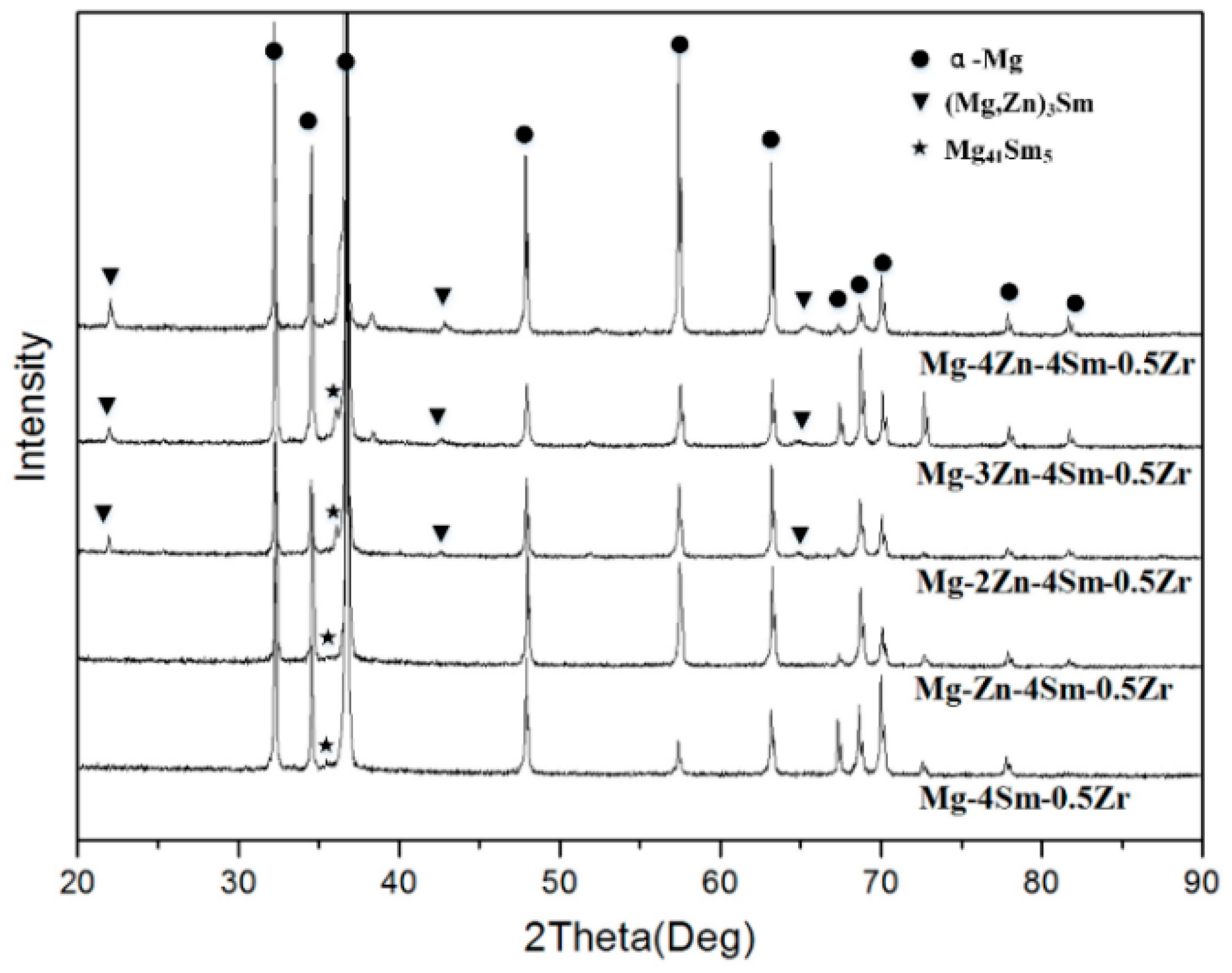
Figure 4 shows the XRD patterns of as-cast Mg–4Sm–xZn–0.5Zr (x = 0, 1, 2, 3, 4 wt %) alloys. As shown in the nethermost curve in Figure 4, Mg–4Sm–0.5Zr alloy consists of Mg41Sm5 phase and α-Mg phase. While the Zn-containing alloys contain a new compound (Mg,Zn)3Sm according to the XRD curves. The results of XRD are consistent with the results of EDS in Table 2. The (Mg,Zn)3Sm phase is similar to (Mg,Zn)3RE phase reported by Zhang et al. [23] and Yuan et al. [24]. The (Mg,Zn)3RE phase has a DO3-type structure with a = 0.72 nm. Figure 5a shows a bright field TEM image of (Mg,Zn)3Sm phase and the sample is taken from the as-cast Mg–4Sm–2Zn–0.5Zr alloy. The SAED (Selected Area Electron Diffraction) pattern in Figure 5b corresponds to the position A in Figure 5a, and the electron beam is parallel to the axis of (Mg,Zn)3Sm phase. By calculation, the interplanar spacing between {220}(Mg, Zn)3Sm is about 0.258 nm, a = 2
× 0.258 nm = 0.729 nm, which agrees well with previous research.
3.2. Microstructures of Solution-Treated Alloys
Figure 6 shows the optical micrographs of solution-treated alloys at 510 °C for 10 h. Comparing with the as-cast alloys, the average size of grain slightly increased at the T4 state. Although the eutectic compounds at grain boundaries are less than those in as-cast alloys, they do not disappear completely. The solution-treated alloys containing high content of Zn have more eutectic compounds. The XRD pattern of the solution-treated alloys are shown in Figure 7, Mg41Sm5 phases and (Mg,Zn)3Sm phase still can be detected in solution-treated alloys. The result reveals that the Mg41Sm5 phases and (Mg,Zn)3Sm phase are thermostable compounds to some degree.
3.3. Microstructures of As-Extruded Alloys
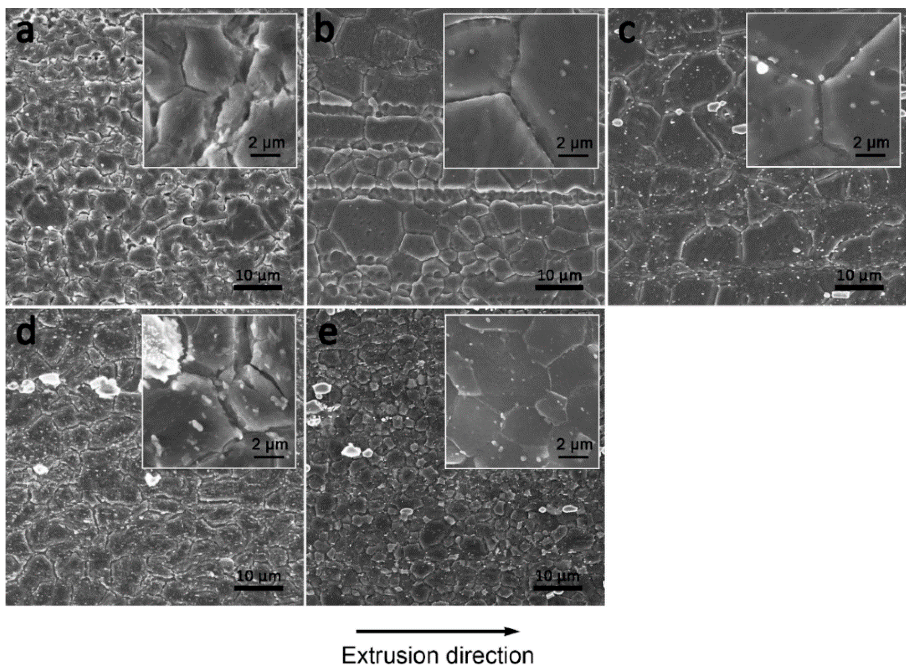
Figure 8 shows the SEM micrographs of as-extruded Mg–4Sm–xZn–0.5Zr alloys observed on the longitudinal section along the extrusion direction under different magnification. Here, it is obvious that almost complete dynamic recrystallization has taken place in all the alloys. After hot extrusion, the grains are obviously refined for each alloy. By calculation, the DRXed grain sizes of as-extruded alloys are 4.0 ± 0.3 μm, 5.1 ± 0.2 μm, 6.2 ± 0.3 μm, 4.5 ± 0.2 μm and 2.4 ± 0.3 μm, respectively. Comparing with the other four alloys, the grains of as-extruded Mg–4Sm–4Zn–0.5Zr alloy are obviously finer. As shown in Figure 8a, spherical particles can hardly be observed in as-extruded Mg–4Sm–0.5Zr alloy. With the increasing Zn content, more and more fine and dispersed phases appear in the as-extruded alloys.
As shown in Figure 8, the second phases in as-extruded Zn-containing alloys have various morphologies with different sizes ranging from dozens of nanometers to several micrometers. Some block-shaped particles with diameter of several micrometers can be observed at the grain boundary and their volume fraction is very few. Apart from the big block-shaped particles, a high number density of white particles can be observed in the as-extruded Zn-containing alloys, especially in high Zn-content alloys. The magnifying SEM images show that the fine particles locate both at grain boundaries and at the interior of the grains.
The XRD patterns in Figure 9 of as-extruded alloys reveal that besides α-Mg, (Mg,Zn)3Sm and Mg41Sm5 phase can be detected in the as-extruded alloys containing Zn. The results are similar to the XRD patterns of as-cast alloys and solution-treated alloys. Comparing the XRD patterns of as-cast alloys (Figure 4), solution-treated alloys (Figure 7) and as-extruded alloys (Figure 9), an interesting phenomenon can be observed in that the XRD peaks of the (Mg,Zn)3Sm phase in as-cast alloys and as-extruded alloys shift toward larger angles with increasing Zn content. The phenomenon is not observed in the XRD patterns of solution-treated alloys.
According to Bragg’s Law λ = 2dsinθ (where λ is radiation wavelength, θ is the usual Bragg angle, and d is interplanar crystal spacing), the peaks shift towards larger angle means that the θ has increased with the increasing of Zn content; at the same time, the d should decrease in order to keep the λ constant. Therefore, it can be concluded that the interplanar spacing of (Mg,Zn)3Sm phase decreases with increasing Zn content in as-cast and as-extruded alloys. Additionally, the interplanar spacing of (Mg,Zn)3Sm phase remains constant with increasing Zn content in the solution-treated alloys. The decrease of interplanar spacing may be attributed to the internal strain in (Mg,Zn)3Sm phase caused by redundant Zn in alloys with increasing Zn content in as-cast and as-extruded alloys. The internal strain is released adequately through solution treatment at 510 °C for 10 h, therefore, the interplanar spacing of (Mg,Zn)3Sm phase in the solution-treated alloy remains constant.
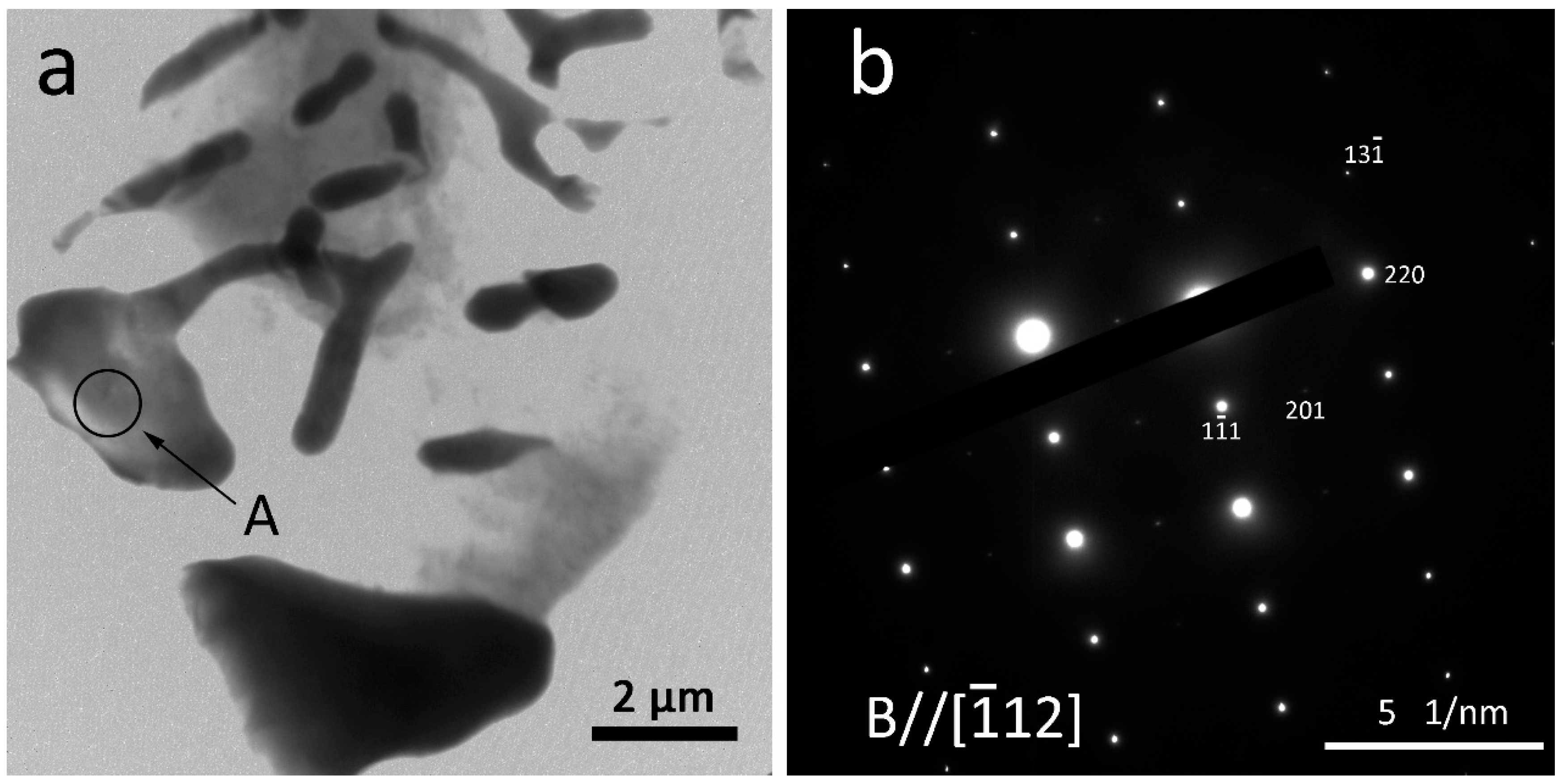
Figure 10 shows a bright field TEM micrograph of ellipsoidal particles with diameter of ~1.5 μm observed in as-extruded Mg–4Sm–2Zn–0.5Zr alloy and corresponding SAED patterns. Figure 10e shows the EDS result taken from the particle in Figure 10a. The EDS result reveals that the atomic ratio of Zn and Sm is ~2.5:1, therefore, the micron-sized particles may be (Mg,Zn)3Sm phase, which are verified by the SAED patterns. As shown in Figure 10b–d, the SAED patterns are taken from the [001], and direction, respectively. These particles have relatively big size and irregular shape in general, and should be the fragmented (Mg,Zn)3Sm phase after hot-extrusion.
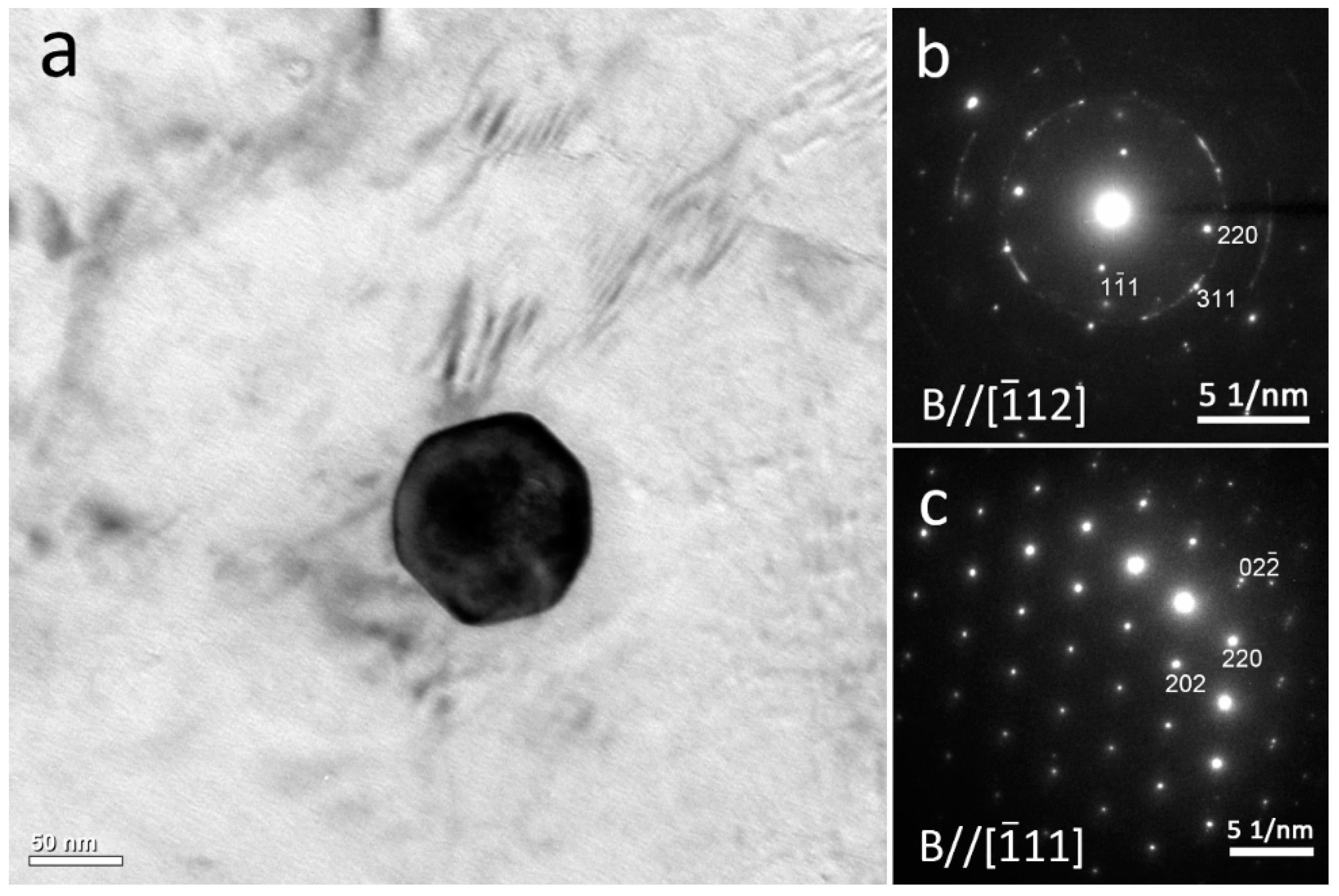
Figure 11 shows a bright field TEM micrograph of a regular polygon particle with a diameter of ~60 nm in as-extruded Mg–4Sm–2Zn–0.5Zr alloy, and the SAED patterns indicate that it is (Mg,Zn)3Sm phase. The fine regular nano-sized particles should be the dynamic precipitates after hot extrusion.
Besides the block-shaped precipitates, some disc-like precipitates also are observed in the as-extruded Mg–4Sm–4Zn–0.5Zr alloy, as shown in Figure 12a. The disc-like precipitates are about 30 nm wide and 500 nm long, and they all lie along the (0001)α–Mg plane of Mg matrix. Figure 12b shows the HRTEM (High Resolution Transmission Electron Microscopy) image of the basal precipitates taken with electron beam paralleling to the direction of Mg matrix. An examination of these basal precipitate discs using HRTEM reveals that most of them form on several successive (0001)α–Mg planes of the matrix phase. The corresponding FFT (Fast Fourier Transform) pattern is shown at the top-right corner of Figure 12b. The SAED pattern recorded from of Mg matrix regions containing disc-like precipitates is shown in Figure 12c. The ambiguously extra diffraction spots are located at the 1/3 and 2/3 positions. This result is similar to the basal precipitates Mg–RE–Zn phase in as-cast Mg–RE–Zn–Zr alloy at T6 state [25]. Therefore, the basal precipitates are proposed to have a hexagonal structure with a = 0.556 nm.
It is well known that precipitation strengthening is an effective way to strengthen Mg alloy, however, many investigations about precipitation focus on the static precipitation, especially Mg–RE alloys [15,18,26,27]. As mentioned by Kabir [22], the formation of strain-induced precipitates depended on deformation temperature, strain, and strain rate. The dynamic precipitates in Kabir’s work mainly distributed at the grain boundaries, while in this paper, the dynamic precipitates can be observed at the grain boundaries and at the interior of the grain, which is consistent with the investigation from Su [28].
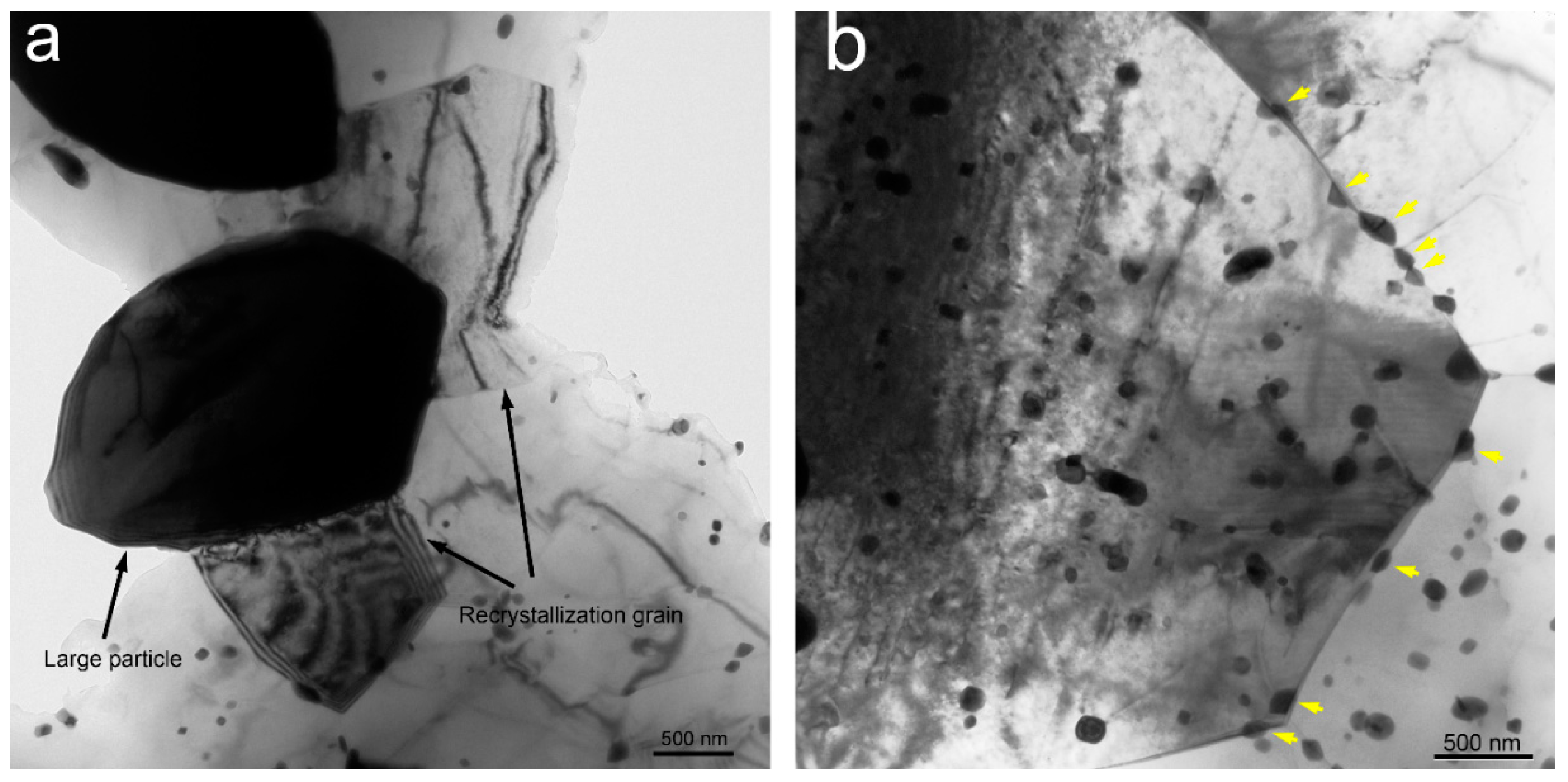
The second phase can influence recrystallization, whether fragmented coarse particles or the dynamic precipitates. The effect of second phases on recrystallization depends on their size, spacing and fraction [29], and lies in three aspects: firstly, the stored energy at the positions of the particles increases the driving pressure for recrystallization; secondly, the large particles (≥1 μm in diameter) may act as nucleation sites for recrystallization; finally, the closely spaced particles may exert a significant pinning effect on both low and high angle grain boundaries [30]. Some evidence reveals that the particle stimulated nucleation of recrystallization (PSN) may occur during the high temperature deformation [30]. In this work, after hot deformation some static recrystallization has been observed in as-extruded Mg–4Sm–4Zn–0.5Zr alloy, and the nucleation site locate at the large particle, as shown in Figure 13a. In the process of hot deformation massive dispersive particles can effectively pin the migration of boundaries and retard the dynamic recrystallization, which leads to fine DRXed grain in the as-extruded alloy. In Figure 13b the dynamic precipitation can be observed at the grain boundary, as indicated by yellow arrows.
It is well known that the DRXed grain size of Mg alloy are influenced by several factors, such as deformation temperature, strain rate, deformation degree and the initial grain size [31]. In this work, except the initial grain size, the other factors are almost the same for all the five kinds of alloys. Previous research revealed that the initial grain size was a more sensitivity factor to influence the DRXed grain size in Mg alloy than in other metals [32]. The coarser initial grain always leads to a coarser DRXed grain through hot deformation, and vice versa. On one hand, the finer initial grain provide more grain boundaries to facilitate nucleating of the dynamic recrystallization. On the other hand, with the initial grain decreasing, the strain corresponding to the peak stress also decreases, therefore, the dynamic recrystallization can occur more easily [33]. In the present paper, the variation trend of grain size of as-cast alloys is mainly as same as that of as-extruded alloys with the Zn content increasing. Moreover, the results agree well with the former research. The DRXed grains of as-extruded Mg–4Sm–4Zn–0.5Zr alloy are obviously finer than those of the other alloys, may be attributed to the massive dispersive particles retarding the dynamic recrystallization and pinning the migration of grain boundaries, which agree with the former research from Kabir [22].
3.4. Mechanical Properties
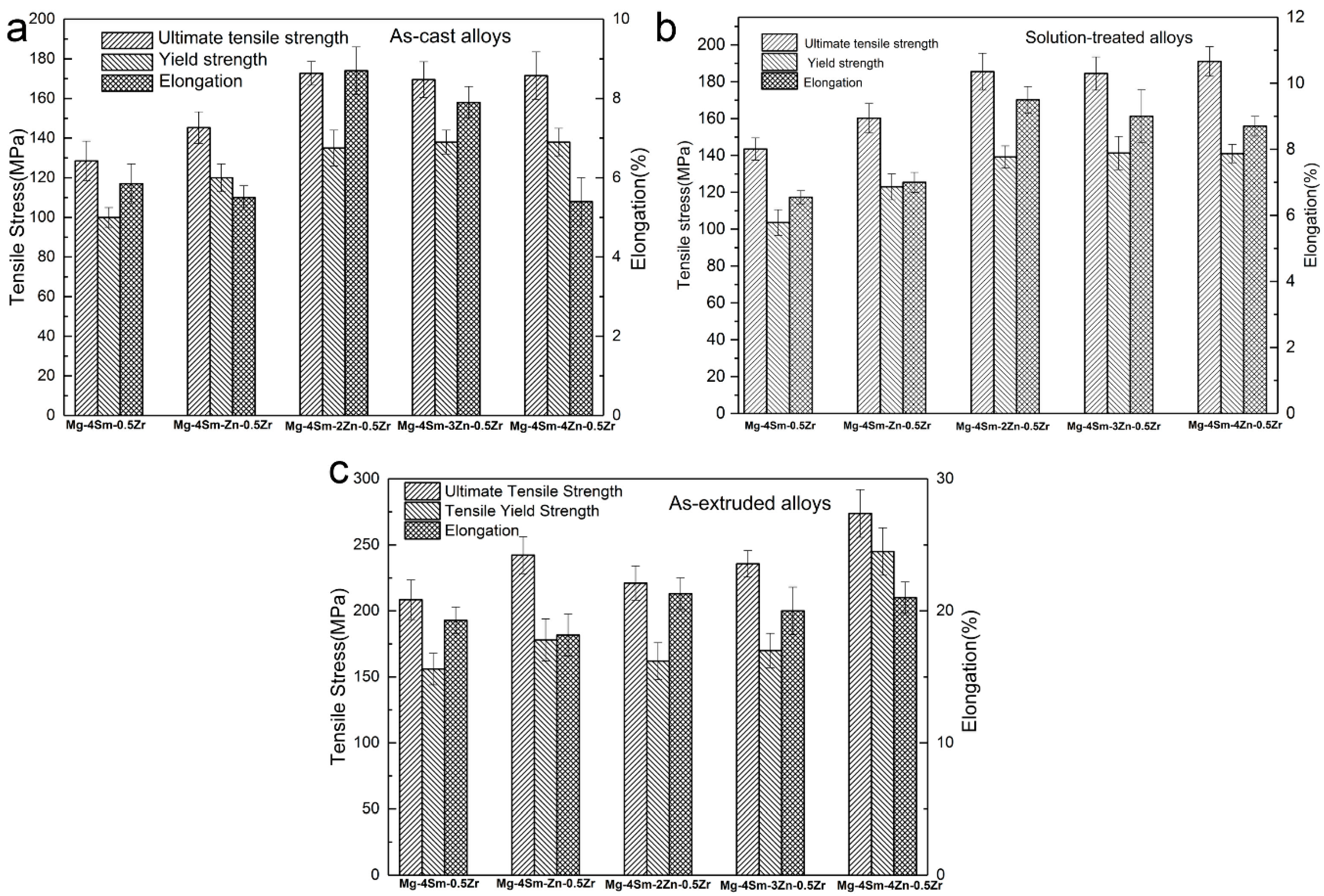
As shown in Figure 14a, when x ≤ 2, it is obvious that the yield strength and ultimate tensile strength of as-cast alloy increases with increasing Zn content. However, when 2 ≤ x ≤ 4, the value of yield strength almost retains a constant of about 135 MPa; at the same time, the elongation has a drop with Zn content increasing. The yield strength σy varies with grain size according to the Hall-Petch equation, , where d is the average grain diameter and and are constants for a particular material. The average grain diameters of the as-cast alloys do not change too much, therefore, the grain size reduction is not the main factor to influence strengthening. Solid-solution strengthening plays an important role in strengthening the alloys. The Zn element has a relatively high solid solubility in Mg matrix, hence the yield strength of as-cast alloy increases with Zn content increasing at first, whereas when the Zn content is greater than 2 wt %, the solid solubility of Zn reach extremum at room temperature, which can explain why the value of yield strength almost retains a constant when x ≥ 2. Moreover, the volume fraction of eutectic compounds increases and the compounds become increasingly coarse, which provides more crack initiations during the tensile test to lead to fracture. Thus, the elongation has an obvious drop with Zn content increasing when x ≥ 2. The as-cast Mg–4Sm–2Zn–0.5Zr alloy exhibits the best comprehensive mechanical properties at room temperature, and the yield strength, ultimate tensile strength and elongation are 132 MPa, 175 MPa and 8.7%, respectively.
Comparing with the tensile properties of as-cast alloys, the ultimate tensile strength and elongation of solution-treated alloys is a bit higher, and the yield strength almost equal to those of as-cast alloys, as shown in Figure 14b. The increasing of elongation and ultimate tensile may be attributed to reduction of the coarse eutectic compounds at grain boundaries. The solution-treated Mg–4Sm–4Zn–0.5Zr alloys exhibits the best comprehensive mechanical properties at room temperature, and the yield strength, ultimate tensile strength and elongation are 191 MPa, 141 MPa and 8.7%.
Figure 14c shows the tensile properties of as-extruded alloys. Comparing with the yield strength and elongation of as-cast alloy, those of as-extruded alloys have clearly improved, which is attributed to the grain refinement after hot extrusion. The fine grains can provide greater total grain boundary to impede dislocation motion. It should be mentioned that grain size reduction improves not only strength, but also the toughness of the alloys. As shown in Figure 7, the volume fraction of second phases increases with Zn content increasing, especially the fine nano-sized phases. It is well known that the operative slip system of Mg is mainly on the basal plane (0001)
and secondly on vertical face planes in the direction at room temperature. At elevated temperatures, slip also can occur on the plane in the direction [3]. On one hand, the massive fine particles promote recrystallization nucleation decreasing the grain size. On the other hand, the massive fine particles can effectively block slip during tensile test. The as-extruded Mg–4Sm–4Zn–0.5Zr alloy exhibits the best comprehensive mechanical properties at room temperature, and the yield strength, ultimate tensile strength and elongation are about 246 MPa, 273 MPa and 21%, respectively. This result is attributed to the massive dispersed nanoscale particles reducing the DRXed grain size and blocking slip of dislocation effectively in as-extruded Mg–4Sm–4Zn–0.5Zr alloy.
Figure 15 shows the stress-strain curves of as-extruded Mg–4Sm–4Zn–0.5Zr alloy at room temperature and 473 K. It can be seen that the as-extruded Mg–4Sm–4Zn–0.5Zr alloy has a relatively good tensile properties at elevated temperature, which should be attributed to the heat-resistant (Mg,Zn)3Sm phase with different sizes blocking not only the motion of dislocation but also the slide of the grain boundary.
3.5. Fracture
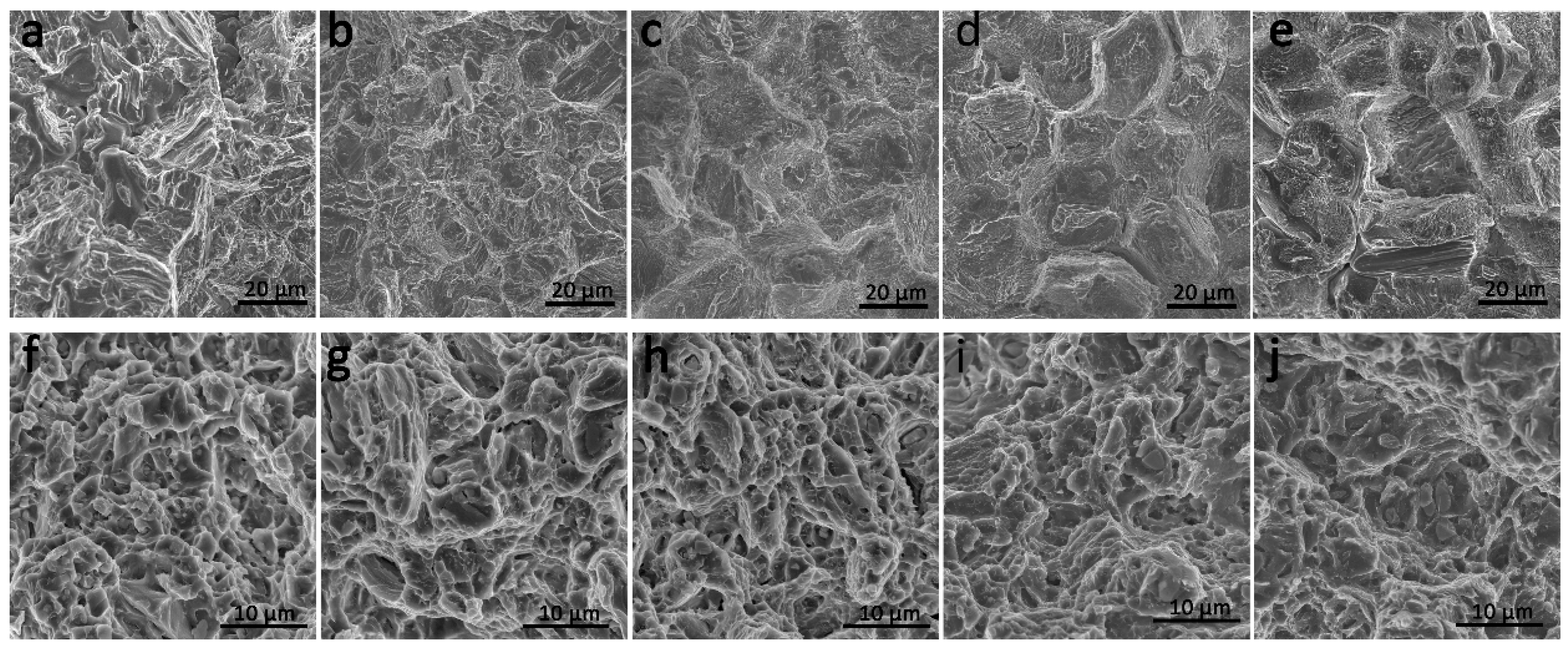
Figure 16 shows the SEM fractographs of tensile tests of as-cast and as-extruded Mg–4Sm–xZn–0.5Zr alloys at room temperature. It is obvious that the fractographs of as-cast alloys mainly consist of cleavage planes, tear ridges and shallow dimples, revealing the poor ductility of as-cast alloys. The coarse ridges and cleavage planes in Figure 16e correspond to the coarse eutectic compounds in as-cast Mg–4Sm–4Zn–0.5Zr alloy, indicating that excessively coarse eutectic compounds are harmful to the toughness of alloy. The abundant ridges and deep dimples observed in Figure 16f,j reveal the excellent plasticity of as-extruded alloys, which is consistent with the high elongations in Figure 14c. In short, the fracture mechanism of as-cast alloys is transgranular cleavage fracture, and the ductility of alloys has been improved much by hot extrusion.
4. Conclusions
- (1)
- The as-cast Mg–4Sm–0.5Zr alloys contains α-Mg matrix and Mg41Sm5 phase. The microstructures of as-cast Mg–4Sm–xZn–0.5Zr (x = 1, 2, 3, 4 wt %) alloys mainly consist of α-Mg matrix, Mg41Sm5 and (Mg,Zn)3Sm.
- (2)
- The as-cast Mg–4Sm–2Zn–0.5Zr alloy exhibits the best comprehensive tensile properties at room temperature among all the as-cast alloys, and YS, UTS and EL are 132 MPa, 175 MPa and 8.7%, respectively.
- (3)
- f Besides the block-shaped precipitates, some disc-like precipitates also are observed in the as-ex elongation are about 246 MPa, 273 MPa and 21%, respectively, which is attributed to the massive dispersed nanoscale particles effectively reducing the DRXed grain size and blocking slip of dislocation. The dynamic precipitates in as-extruded Mg–4Sm–4Zn–0.5Zr alloy containing basal precipitates having a hexagonal structure with a = 0.556 nm.
Acknowledgments
This project is supported by National Natural Science Foundation of China (Grant No. 51575231).
Author Contributions
Chaojie Che, Fanxing Meng performed the data collection, figures, and data analyses; Chaojie Che wrote the original manuscript; Zhongyi Cai designed the experiments and revised the manuscript; Liren Cheng contributed to data analyses, data interpretation and manuscript revision; Zhen Yang participated in data collection and analyses.
Conflicts of Interest
The author declare no conflict of interest.
References
- Pan, F.; Yang, M.; Chen, X. A review on casting magnesium alloys: Modification of commercial alloys and development of new alloys. J. Mater. Sci. Technol. 2016, 32, 1211–1221. [Google Scholar] [CrossRef]
- Sarker, D.; Friedman, J.; Chen, D.L. Twin growth and texture evolution in an extruded AM30 magnesium alloy during compression. J. Mater. Sci. Technol. 2014, 30, 884–887. [Google Scholar] [CrossRef]
- Mordike, B.L.; Ebert, T. Magnesium properties-applications-potential. Mater. Sci. Eng. A 2001, 302, 37–45. [Google Scholar] [CrossRef]
- Rokhlin, L.L.; Dobatkina, T.V.; Nikitina, N.I. Constitution and properties of the ternary magnesium alloys containing two rare-earth metals of different subgroups. Mater. Sci. Forum 2003, 419–422, 291–296. [Google Scholar] [CrossRef]
- Nie, J.F.; Muddle, B.C. Precipitation in magnesium alloy WE54 during isothermal ageing at 250 degrees C. Scr. Mater. 1999, 40, 1089–1094. [Google Scholar] [CrossRef]
- Li, D.; Wang, Q.; Ding, W. Characterization of phases in Mg–4Y–4Sm–0.5Zr alloy processed by heat treatment. Mater. Sci. Eng. A 2006, 428, 295–300. [Google Scholar] [CrossRef]
- Antion, C.; Donnadieu, P.; Perrard, F.; Deschamps, A.; Tassin, C.; Pisch, A. Hardening precipitation in a Mg-4Y-3Re alloy. Acta Mater. 2003, 51, 5335–5348. [Google Scholar] [CrossRef]
- Gröbner, J.; Kozlov, A.; Fang, X.Y.; Geng, J.; Nie, J.F.; Schmid-Fetzer, R. Phase equilibria and transformations in ternary Mg-rich Mg–Y–Zn alloys. Acta Mater. 2012, 60, 5948–5962. [Google Scholar] [CrossRef]
- He, S.M.; Zeng, X.Q.; Peng, L.M.; Gao, X.; Nie, J.F.; Ding, W.J. Microstructure and strengthening mechanism of high strength Mg–10Gd–2Y–0.5Zr alloy. J. Alloys Compd. 2007, 427, 316–323. [Google Scholar] [CrossRef]
- Li, D.J.; Zeng, X.Q.; Dong, J.; Zhai, C.Q.; Ding, W.J. Microstructure evolution of Mg–10Gd–3Y–1.2Zn–0.4Zr alloy during heat-treatment at 773k. J. Alloys Compd. 2009, 468, 164–169. [Google Scholar] [CrossRef]
- Hou, X.; Cao, Z.; Zhao, L.; Wang, L.; Wu, Y.; Wang, L. Microstructure, texture and mechanical properties of a hot rolled Mg–6.5Gd–1.3Nd–0.7Y–0.3Zn alloy. Mater. Des. 2012, 34, 776–781. [Google Scholar] [CrossRef]
- Zheng, K.Y.; Dong, J.; Zeng, X.Q.; Ding, W.J. Precipitation and its effect on the mechanical properties of a cast Mg–Gd–Nd–Zr alloy. Mater. Sci. Eng. A 2008, 489, 44–54. [Google Scholar] [CrossRef]
- Nie, J.F.; Gao, X.; Zhu, S.M. Enhanced age hardening response and creep resistance of Mg–Gd alloys containing Zn. Scr. Mater. 2005, 53, 1049–1053. [Google Scholar] [CrossRef]
- Mostafa, A.; Medraj, M. Experimental investigation of the Mg-Nd-Zn isothermal section at 300 degrees C. Metals 2015, 5, 84–101. [Google Scholar] [CrossRef]
- Xia, X.; Sun, W.; Luo, A.A.; Stone, D.S. Precipitation evolution and hardening in Mg-Sm-Zn-Zr alloys. Acta Mater. 2016, 111, 335–347. [Google Scholar] [CrossRef]
- Qi, H.Y.; Huang, G.X.; Bo, H.; Xu, G.L.; Liu, L.B.; Jin, Z.P. Thermodynamic description of the Mg–Nd–Zn ternary system. J. Alloys Compd. 2011, 509, 3274–3281. [Google Scholar] [CrossRef]
- Zheng, X.; Dong, J.; Xiang, Y.; Chang, J.; Wang, F.; Jin, L.; Wang, Y.; Ding, W. Formability, mechanical and corrosive properties of Mg–Nd–Zn–Zr magnesium alloy seamless tubes. Mater. Des. 2010, 31, 1417–1422. [Google Scholar] [CrossRef]
- Saito, K.; Hiraga, K. The structures of precipitates in an Mg-0.5 at %Nd age-hardened alloy studied by HAADF-STEM technique. Mater. Trans. 2011, 52, 1860–1867. [Google Scholar] [CrossRef]
- Yuan, M.; Zheng, Z. Effects of Zn on the microstructures and mechanical properties of Mg–3Sm–0.5Gd–xZn–0.5Zr (x = 0, 0.3 and 0.6) alloy. J. Alloys Compd. 2014, 590, 355–361. [Google Scholar] [CrossRef]
- Xia, X.; Luo, A.A.; Stone, D.S. Precipitation sequence and kinetics in a Mg-4Sm-1Zn-0.4Zr (wt %) alloy. J. Alloys Compd. 2015, 649, 649–655. [Google Scholar] [CrossRef]
- Dogan, E.; Wang, S.; Vaughan, M.W.; Karaman, I. Dynamic precipitation in Mg-3Al-1Zn alloy during different plastic deformation modes. Acta Mater. 2016, 116, 1–13. [Google Scholar] [CrossRef]
- Kabir, A.S.H.; Sanjari, M.; Su, J.; Jung, I.H.; Yue, S. Effect of strain-induced precipitation on dynamic recrystallization in Mg-Al-Sn Alloys. Mater. Sci. Eng. A Struct. 2014, 616, 252–259. [Google Scholar] [CrossRef]
- Zhang, S.; Yuan, G.Y.; Lu, C.; Ding, W.J. The relationship between (mg,zn)3re phase and 14h-lpso phase in Mg–Gd–Y–Zn–Zr alloys solidified at different cooling rates. J. Alloys Compd. 2011, 509, 3515–3521. [Google Scholar] [CrossRef]
- Yuan, M.; Zheng, Z.Q. Effects of heat treatment on microstructure and mechanical properties of Mg–2.6Sm–1.3Gd–0.6Zn–0.5Zr alloy. Mater. Sci. Technol. 2014, 30, 261–267. [Google Scholar] [CrossRef]
- Ping, D.H.; Hono, K.; Nie, J.F. Atom probe characterization of plate-like precipitates in a Mg-Re-Zn-Zr casting alloy. Scr. Mater. 2003, 48, 1017–1022. [Google Scholar] [CrossRef]
- Zheng, J.X.; Zhou, W.M.; Chen, B. Precipitation in Mg-Sm binary alloy during isothermal ageing: Atomic-scale insights from scanning transmission electron microscopy. Mater. Sci. Eng. A Struct. 2016, 669, 304–311. [Google Scholar] [CrossRef]
- Nie, J.F. Precipitation and hardening in magnesium alloys. Metall. Mater. Trans. A 2012, 43, 3891–3939. [Google Scholar] [CrossRef]
- Su, J.; Kaboli, S.; Kabir, A.S.H.; Jung, I.H.; Yue, S. Effect of dynamic precipitation and twinning on dynamic recrystallization of micro-alloyed Mg–Al–Ca alloys. Mater. Sci. Eng. A 2013, 587, 27–35. [Google Scholar] [CrossRef]
- Robson, J.D.; Henry, D.T.; Davis, B. Particle effects on recrystallization in magnesium–manganese alloys: Particle-stimulated nucleation. Acta Mater. 2009, 57, 2739–2747. [Google Scholar] [CrossRef]
- Humphreys, F.J.; Hatherly, M. Recrystallization and Related Annealing Phenomena, 2nd ed.; Elsevier: Oxford, UK, 2004. [Google Scholar]
- Chen, Z.H.; Xu, F.Y.; Fu, D.F.; Xia, W.J. The dynamic recrystallization of magnesium alloys. Chem. Ind. Eng. Prog. 2006, 25, 7. [Google Scholar]
- Barnett, M.R. Recrystallization during and following hot working of magnesium alloy az31. Mater. Sci. Forum 2003, 419–422, 503–508. [Google Scholar] [CrossRef]
- Barnett, M.R.; Beer, A.G.; Atwell, D.; Oudin, A. Influence of grain size on hot working stresses and microstructures in Mg-3Al-lZn. Scr. Mater. 2004, 51, 19–24. [Google Scholar] [CrossRef]
Figure 1.
The differential scanning calorimetry (DSC) curve of as-cast Mg–4Sm–4Zn–0.5Zr alloy.
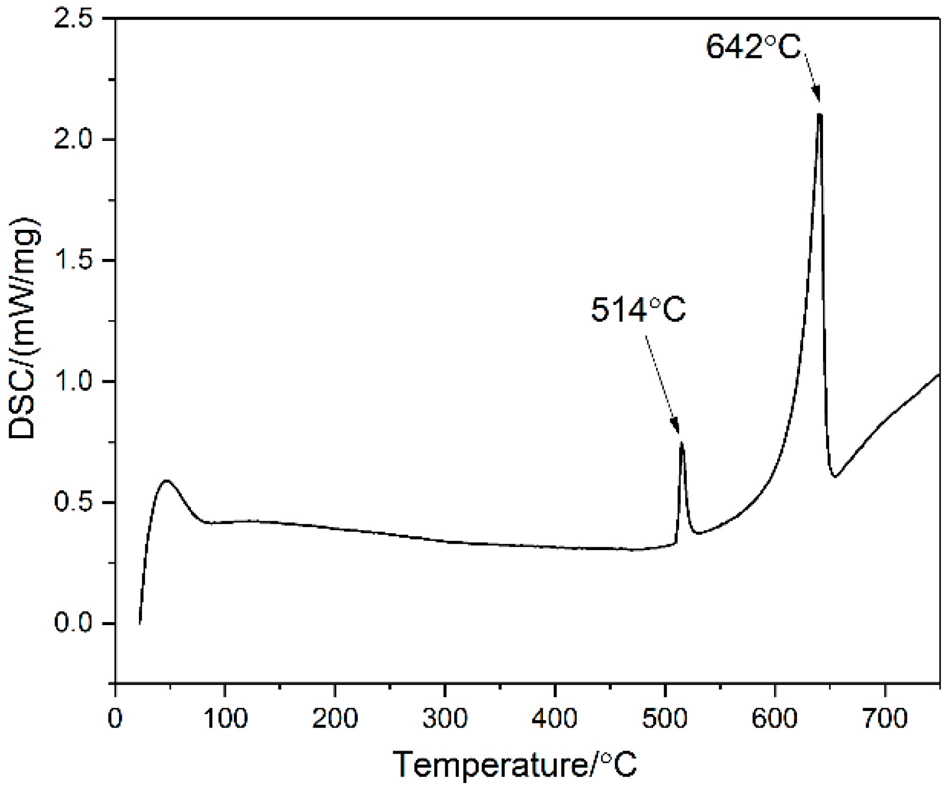
Figure 2.
Optical micrographs of as-cast Mg–4Sm–xZn–0.5Zr alloys: (a) x = 0; (b) x = 1; (c) x = 2; (d) x = 3; (e) x = 4.
Figure 2.
Optical micrographs of as-cast Mg–4Sm–xZn–0.5Zr alloys: (a) x = 0; (b) x = 1; (c) x = 2; (d) x = 3; (e) x = 4.
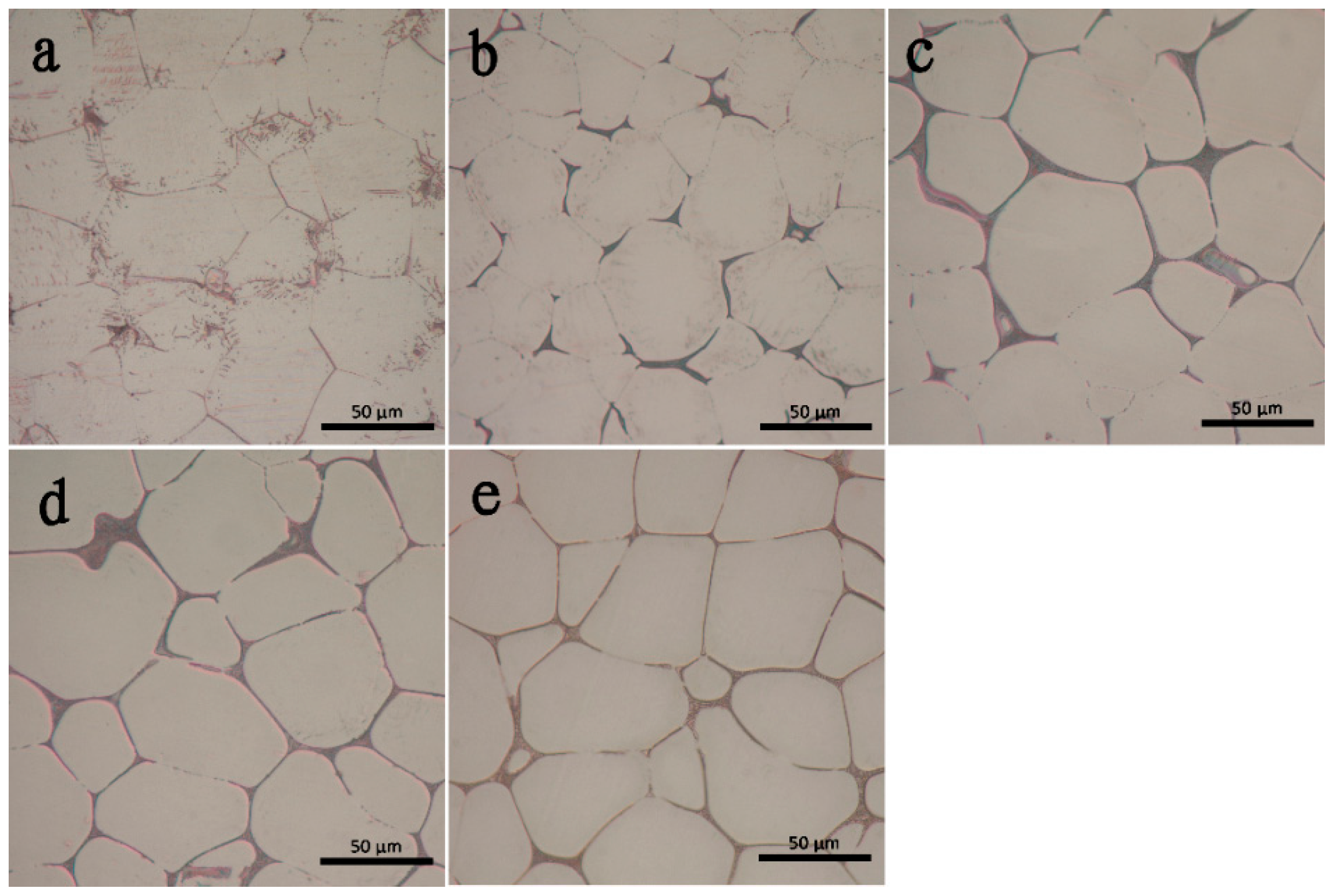
Figure 3.
The scanning electron microscope (SEM) micrographs of as-cast Mg–4Sm–xZn–0.5Zr alloys: (a) x = 0; (b) x = 1; (c) x = 2; (d) x = 3; (e) x = 4. The hollow rectangle at top-right corner in Figure 2a is the magnifying picture at grain boundary.
Figure 3.
The scanning electron microscope (SEM) micrographs of as-cast Mg–4Sm–xZn–0.5Zr alloys: (a) x = 0; (b) x = 1; (c) x = 2; (d) x = 3; (e) x = 4. The hollow rectangle at top-right corner in Figure 2a is the magnifying picture at grain boundary.
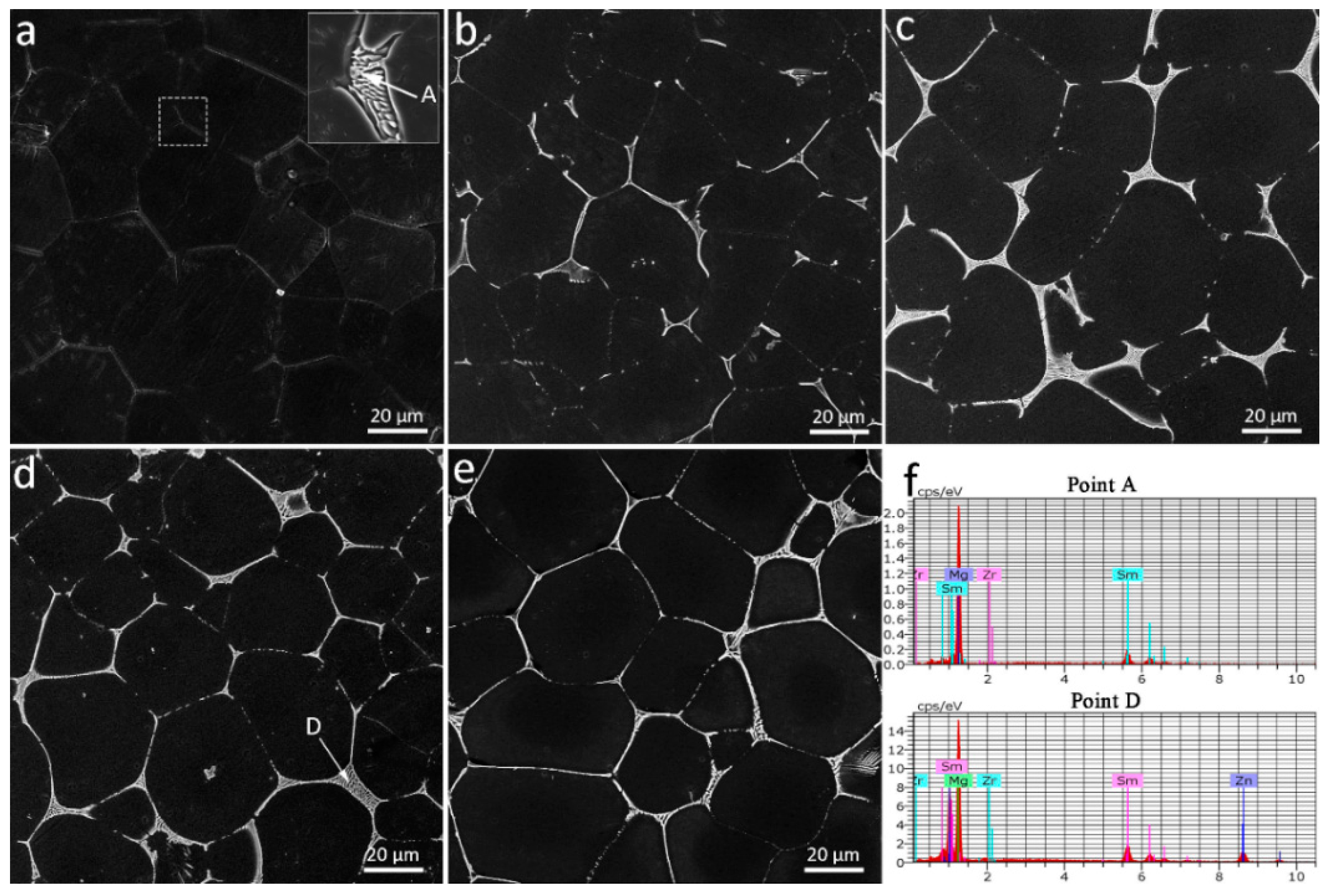
Figure 4.
The X-ray diffractometer (XRD) patterns of as-cast Mg–4Sm–xZn–0.5Zr (x = 0, 1, 2, 3, 4) (wt %) alloys.
Figure 4.
The X-ray diffractometer (XRD) patterns of as-cast Mg–4Sm–xZn–0.5Zr (x = 0, 1, 2, 3, 4) (wt %) alloys.
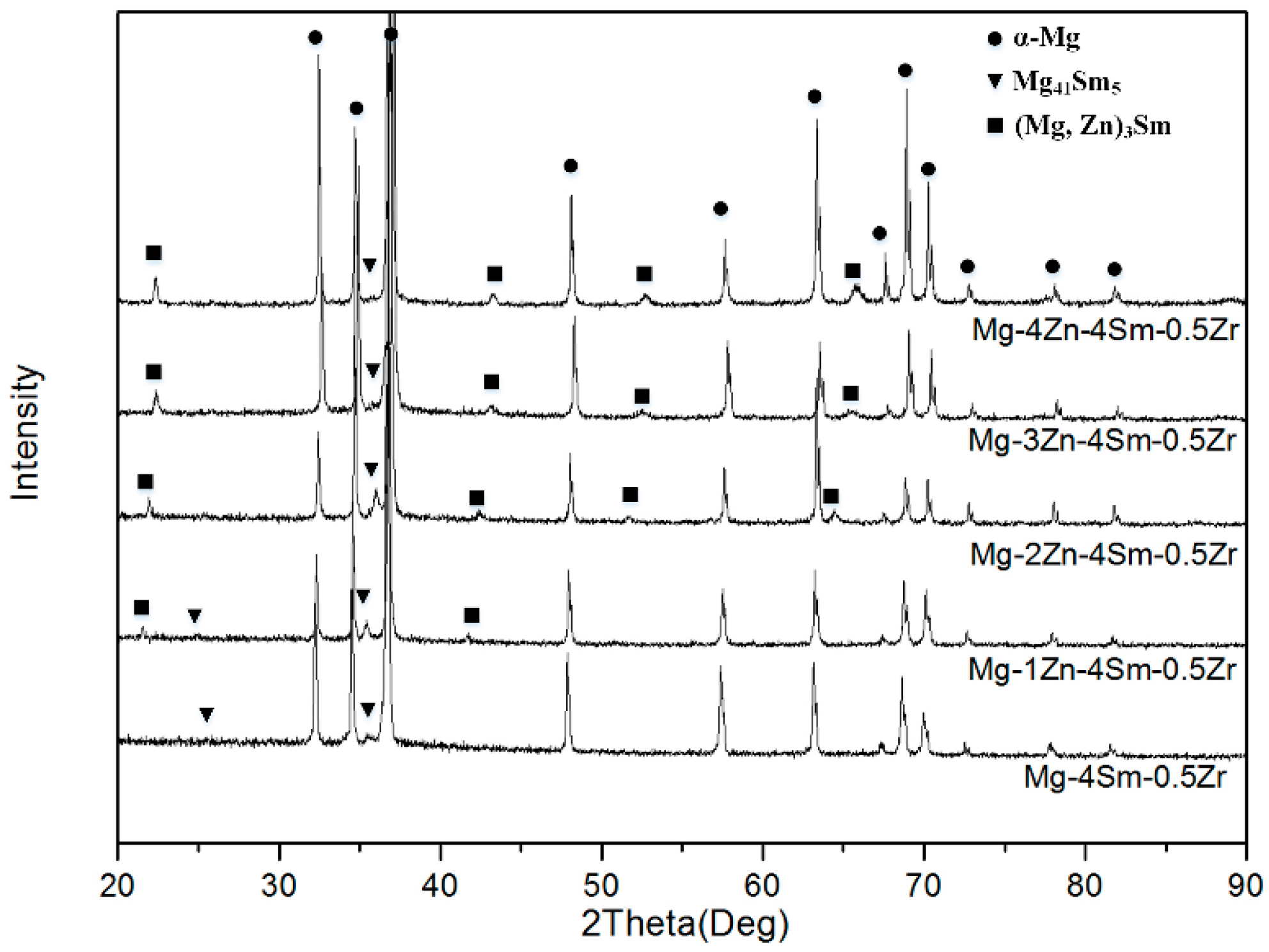
Figure 5.
(a) A bright field transmission electron microscope (TEM) image of as-cast Mg–4Sm–2Zn–0.5Zr alloy and (b) the SAED patterns taken from the position A in Figure 4a, the zone axis is .
Figure 5.
(a) A bright field transmission electron microscope (TEM) image of as-cast Mg–4Sm–2Zn–0.5Zr alloy and (b) the SAED patterns taken from the position A in Figure 4a, the zone axis is .

Figure 6.
The optical micrographs of solution-treated Mg–4Sm–xZn–0.5Zr alloys: (a) x = 0; (b) x = 1; (c) x = 2; (d) x = 3; (e) x = 4.
Figure 6.
The optical micrographs of solution-treated Mg–4Sm–xZn–0.5Zr alloys: (a) x = 0; (b) x = 1; (c) x = 2; (d) x = 3; (e) x = 4.

Figure 7.
The XRD patterns of solution-treated Mg–4Sm–xZn–0.5Zr (x = 0, 1, 2, 3, 4) (wt %) alloys.

Figure 8.
The SEM micrographs of as-extruded Mg–4Sm–xZn–0.5Zr alloys observed on the longitudinal section along the extrusion direction: (a) x = 0; (b) x = 1; (c) x = 2; (d) x = 3; (e) x = 4.
Figure 8.
The SEM micrographs of as-extruded Mg–4Sm–xZn–0.5Zr alloys observed on the longitudinal section along the extrusion direction: (a) x = 0; (b) x = 1; (c) x = 2; (d) x = 3; (e) x = 4.

Figure 9.
The XRD patterns of solution-treated Mg–4Sm–xZn–0.5Zr (x = 0, 1, 2, 3, 4) (wt %) alloys.
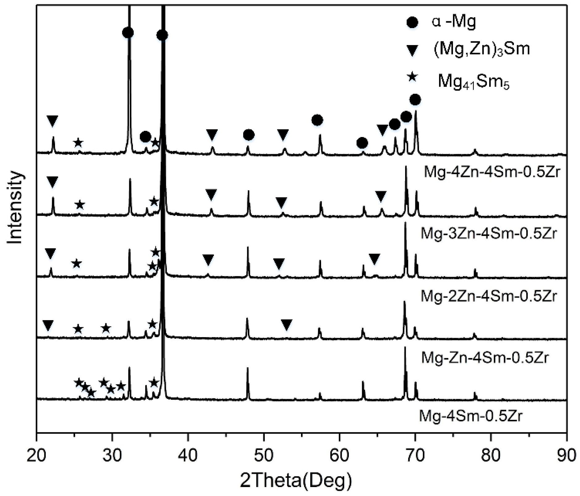
Figure 10.
The bright field TEM micrograph of the micron-sized phase observed in as-extruded Mg–4Sm–2Zn–0.5Zr alloy for (a) and the corresponding SAED patterns taken along the [001] direction for (b), the
direction for (c) and the direction for (d), respectively. (e) The EDS pattern of the micron-sized phase in Figure 10a.

Figure 11.
The bright field TEM micrograph of the nanoscale phase observed in as-extruded Mg–4Sm–2Zn–0.5Zr alloy for (a), and corresponding SAED patterns taken along the direction for (b) and the direction for (c).
Figure 11.
The bright field TEM micrograph of the nanoscale phase observed in as-extruded Mg–4Sm–2Zn–0.5Zr alloy for (a), and corresponding SAED patterns taken along the direction for (b) and the direction for (c).

Figure 12.
(a) The bright field TEM micrograph of disc-like precipitates observed in as-extruded Mg–4Sm–4Zn–0.5Zr alloy, zone axis: ; (b) the HRTEM micrograph of disc-like precipitates observed in as-extruded Mg–4Sm–4Zn–0.5Zr alloy, zone axis: ; (c) the SAED pattern taken from the Mg matrix containing the disc-like precipitates in as-extruded Mg–4Sm–4Zn–0.5Zr alloy, zone axis: .

Figure 13.
Bright field TEM micrographs taken from as-extruded Mg–4Sm–4Zn–0.5Zr alloy: (a) the large particles can promote recrystallization after hot extrusion; (b) fine and dispersive particles can pin the grain boundaries.
Figure 13.
Bright field TEM micrographs taken from as-extruded Mg–4Sm–4Zn–0.5Zr alloy: (a) the large particles can promote recrystallization after hot extrusion; (b) fine and dispersive particles can pin the grain boundaries.

Figure 14.
The tensile properties of as-cast, solution-treated and as-extruded Mg–4Sm–xZn–0.5Zr (x = 0, 1, 2, 3, 4 wt %) alloys at room temperature.
Figure 14.
The tensile properties of as-cast, solution-treated and as-extruded Mg–4Sm–xZn–0.5Zr (x = 0, 1, 2, 3, 4 wt %) alloys at room temperature.

Figure 15.
The stress-strain curves of as-extruded Mg–4Sm–4Zn–0.5Zr alloy at room temperature and 473 K.
Figure 15.
The stress-strain curves of as-extruded Mg–4Sm–4Zn–0.5Zr alloy at room temperature and 473 K.
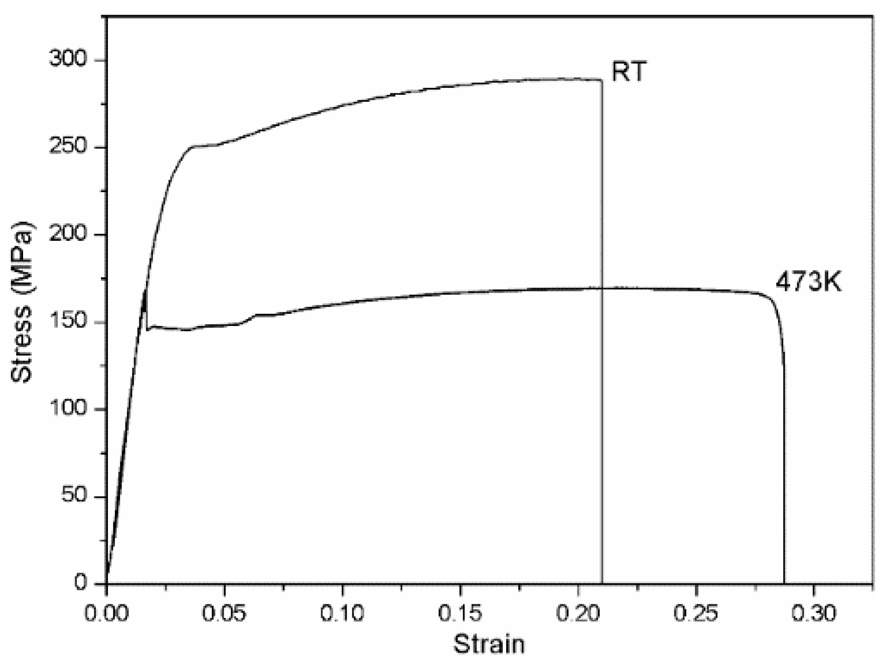
Figure 16.
SEM fractographs of tensile tests of as-cast (a–e) and as-extruded (f–j) Mg–4Sm–xZn–0.5Zr alloys at room temperature: (a,f) x = 0; (b,g) x = 1; (c,h) x = 2; (d,i) x = 3; (e,j) x = 4.
Figure 16.
SEM fractographs of tensile tests of as-cast (a–e) and as-extruded (f–j) Mg–4Sm–xZn–0.5Zr alloys at room temperature: (a,f) x = 0; (b,g) x = 1; (c,h) x = 2; (d,i) x = 3; (e,j) x = 4.


Table 1.
Chemical compositions of the as-cast alloys with different zinc contents.
| Nominal Alloys | Composition (wt %) | |||
|---|---|---|---|---|
| Mg–4Sm–xZn–0.5Zr | Mg | Sm | Zn | Zr |
| Mg–4Sm–0.5Zr | Balance | 3.50 | - | 0.40 |
| Mg–4Sm–1Zn–0.5Zr | Balance | 3.74 | 0.82 | 0.40 |
| Mg–4Sm–2Zn–0.5Zr | Balance | 4.06 | 1.80 | 0.51 |
| Mg–4Sm–3Zn–0.5Zr | Balance | 4.21 | 2.79 | 0.60 |
| Mg–4Sm–4Zn–0.5Zr | Balance | 4.10 | 3.67 | 0.40 |
Table 2.
The chemical compositions of second phases in Figure 2a,d analyzed by EDS.
Table 2.
The chemical compositions of second phases in Figure 2a,d analyzed by EDS.
| Position | Elements | ||||
|---|---|---|---|---|---|
| Mg K | Sm L | Zn K | Zr L | ||
| Point A | Wt % | 53.53 | 43.61 | - | 2.86 |
| At % | 87.27 | 11.49 | - | 1.24 | |
| Point D | Wt % | 47.78 | 26.13 | 23.29 | 2.79 |
| At % | 77.81 | 6.88 | 14.10 | 1.21 | |
© 2017 by the authors. Licensee MDPI, Basel, Switzerland. This article is an open access article distributed under the terms and conditions of the Creative Commons Attribution (CC BY) license (http://creativecommons.org/licenses/by/4.0/).
Share and Cite
MDPI and ACS Style
Che, C.; Cai, Z.; Cheng, L.; Meng, F.; Yang, Z. The Microstructures and Tensile Properties of As-Extruded Mg–4Sm–xZn–0.5Zr (x = 0, 1, 2, 3, 4 wt %) Alloys. Metals 2017, 7, 281. https://doi.org/10.3390/met7070281
AMA Style
Che C, Cai Z, Cheng L, Meng F, Yang Z. The Microstructures and Tensile Properties of As-Extruded Mg–4Sm–xZn–0.5Zr (x = 0, 1, 2, 3, 4 wt %) Alloys. Metals. 2017; 7(7):281. https://doi.org/10.3390/met7070281
Chicago/Turabian StyleChe, Chaojie, Zhongyi Cai, Liren Cheng, Fanxing Meng, and Zhen Yang. 2017. "The Microstructures and Tensile Properties of As-Extruded Mg–4Sm–xZn–0.5Zr (x = 0, 1, 2, 3, 4 wt %) Alloys" Metals 7, no. 7: 281. https://doi.org/10.3390/met7070281
Note that from the first issue of 2016, this journal uses article numbers instead of page numbers. See further details here.