Precipitate Stability in a Zr–2.5Nb–0.5Cu Alloy under Heavy Ion Irradiation
by
 ,
,
Qingshan Dong
1, 
Zhongwen Yao
1,*,
Qiang Wang
1,
Hongbing Yu
1,
Mark A. Kirk
2 and
Mark R. Daymond
1,* 1
Department of Mechanical and Materials Engineering, Queen’s University, Kingston, ON K7L 3N6, Canada
2
Material Science Division Argonne National Laboratory, Argonne, IL 60439, USA
*
Authors to whom correspondence should be addressed.
Metals 2017, 7(8), 287; https://doi.org/10.3390/met7080287
Submission received: 4 July 2017
/
Revised: 21 July 2017
/
Accepted: 24 July 2017
/
Published: 27 July 2017
(This article belongs to the Special Issue Zirconium Alloys)
Abstract
:The stability of precipitates in Zr–2.5Nb–0.5Cu alloy under heavy ion irradiation from 100 °C to 500 °C was investigated by quantitative Chemi-STEM EDS analysis. Irradiation results in the crystalline to amorphous transformation of Zr2Cu between 200 °C and 300 °C, but the β–Nb remains crystalline at all temperatures. The precipitates are found to be more stable in starting structures with multiple boundaries than in coarse grain structures. There is an apparent increase of the precipitate size and a redistribution of the alloying element in certain starting microstructures, while a similar size change or alloying element redistribution is not detected or only detected at a much higher temperature in other starting microstructures after irradiation.
1. Introduction
The stability of precipitates is crucially important when assessing the mechanical properties and corrosion behavior of reactor materials. It is known that irradiation has a remarkable effect on precipitate stability. It may cause the dissolution, precipitation, growth, and/or amorphization of precipitates, the redistribution of alloying elements, and other associated microstructural changes. In the Zircaloys, the radiation-induced the dissolution of Zr(Cr,Fe)2 and Zr2(Ni,Fe) secondary precipitation in the matrix and at grain boundaries, and the depletion of Cr and Fe from the precipitates have been reported by many authors [1,2,3,4,5,6]. In Zr–Nb alloys, the dissolution of Nb and the redistribution of Fe are also clearly observed under higher dose irradiation (>3 dpa) [3,7]. These changes will affect the material performance in the reactors such as corrosion behavior and irradiation growth. Generally, a finer size and more homogeneous distribution of precipitates benefits the corrosion resistance in Zircaloys [8,9]. In Zr–Nb alloys, the super-saturation of Nb in the matrix was demonstrated to degrade corrosion resistance; thus a full precipitation of β–Nb either from α–Zr or β–Zr is recommended [10,11,12]. It is reported that accelerated irradiation growth is related to the appearance of <c> component vacancy dislocation loops on the basal plane and Fe concentration in the matrix [13,14]. It is believed that an increase of the Fe solute concentration promotes the formation of <c> dislocation loops and consequently increases the growth strain in the material [13]. Furthermore, interfaces of incoherent precipitates can act as effective sinks for interstitials and vacancies to recombine and hence decrease the propensity for accelerated growth [15]. As Fe has a significant effect on the diffusional characteristics of vacancies in Zr, an increasing Fe concentration in the matrix may also decrease the magnitude of the irradiation growth rate [14,16].
Zr–2.5Nb–0.5Cu alloy has been proposed as a potential replacement for Inconel X-750 alloy for future spacer installations in CANDU (a registered trademark of Atomic Energy of Canada Ltd. (AECL) used under exclusive license by Candu Energy Inc, Mississauga, ON, Canada) reactors [17]. This alloy was widely used for spacers in early CANDU reactors; however, the in-reactor movement of loose-fitting Zr–2.5Nb–0.5Cu spacers led to many design challenges [18]. In future designs, it is anticipated that the Zr–2.5Nb–0.5Cu will be of a tight-fitting design; however, irradiation growth and creep will still result in a dimensional change of the spacer. The effects of irradiation on the microstructure are important when assessing creep relaxation and growth during the operation of the reactor. Therefore, the assessment of irradiation effects on this material is vital. In-reactor neutron irradiation is the best way to determine the material’s in-reactor properties. However, it is very costly, time consuming, and makes the samples hard to handle due to induced radioactivity. Heavy ion irradiation has been proven to be an excellent alternate to neutron irradiation for the simulation of neutron irradiation damage in Zr alloys because it does not have the drawbacks of neutron irradiation [15]. However, the results must be interpreted in light of the differences in irradiation conditions, most obviously a typically much higher damage rate.
In the past few decades, some research works have reported the effect of irradiation on precipitate and microstructure stability in Zr–2.5Nb [3,7]. A temperature and irradiation fluence dependent precipitate stability and the distribution of alloying elements was reported. High temperatures and high doses will enhance the dissolution of β–Zr and the depletion of Fe from the particles to the matrix [3,5,7,19]. However, the microstructure and precipitates of the as-processed Zr–2.5Nb pressure tube alloy have many differences to the proposed Zr spacer material. In Zr–2.5Nb–0.5Cu, multiple structures and precipitates are formed, which improve its strength so that it can withstand the load from the pressure tube [20]. Hitherto, the effect of irradiation on intermetallic compounds in these structures and this material has not been studied in any detail. In this study, a quantitative TEM (transmission electron microscopy) and Chemi-STEM EDS (energy dispersive spectroscopy) analysis was conducted to investigate precipitate stability under heavy ion irradiation.
2. Materials and Methods
The material used in this study is a Zr–2.5Nb–0.5Cu spring wire material. The nominal chemical composition was 2.5Nb, 0.5Cu, and 0.1Fe in wt %. More details of the source material are provided in Reference [20].
To prepare TEM samples, slices from the as-received spring were cut off and ground to about 100 nm. Standard TEM 3 mm diameter disc samples were punched out from the thin foils and electropolished with a Tenupol-5 twin-jet electro-polisher using 10% perchloric acid in 90% methanol at a temperature of −40 °C. It is challenging to prepare the TEM samples with a maximum width less than 0.8 mm; a novel method was proposed and is reported in detail elsewhere [20].
The heavy ion irradiation was carried out at the Intermediate Voltage Electron Microscope Tandem Facility (IVEM-Tandem) at Argonne National Laboratory (Argonne, IL, USA). The facility includes a Hitachi H-9000 NAR TEM interfaced to a 2 MV tandem ion accelerator. The TEM thin foil specimens were irradiated under 600 KeV Kr2+ with a flux of 0.6 × 10¹⁶ m−2s−1 at 100 °C to 500 °C to a total fluence of 6.0 × 10¹⁶ m−2. According to the SRIM (stopping and range of ions in matter) calculations carried out with an ion beam angle of 15°, 1 MeV Kr2+ ions, and a displacement energy of 40 eV for Zr [21], the dose rate during the heavy ion irradiation was approximately 10−3 dpa/s, and, correspondingly, the final accumulated irradiation damage is 10 dpa. The SRIM calculations were done using the Kinchin-Pease formulation.
The pre-irradiation and post-irradiation S/TEM characterizations were performed on a FEI Tecnai Osiris S/TEM microscope in the Reactor Material Testing Laboratory (RMTL) at Queen’s University (Kingston, ON, Canada). The TEM microscope is equipped with four super X-ray spectrum detectors, which allow the fast acquisition of the X-ray spectrum. For each acquisition, at least 1200 ms line scan dwelling time was used on a 1024 × 1024 map. Particle size measurement was carried out in Image-Pro Plus software. The measurement of the nominal precipitate diameter before and after irradiation is based on the measured area of the particles and assumed circularity. For each measurement, more than 20 particles are used. The alloying element line distribution profiles before and after irradiation were measured at the same location in Esprit software. To minimize the uncertainties resulting from the line measuring locations, the data from four adjacent parallel lines were averaged.
3. Results
Figure 1 shows the microstructure of the as-received material. It contains three types of microstructures; Widmanstätten (type i, noted as A in Figure 1), α–Zr grains without precipitates (type ii, B in Figure 1), and α–Zr grains with precipitates (type iii, C in Figure 1). Three types of precipitates, namely, Zr2Cu, β–Nb, and Zr2Fe, are distributed in the type i and type iii structures. In the type i structure, the precipitates are mainly located within the martensite plate boundaries and the twin boundaries, while, in the type iii structure, the precipitates are homogenously distributed. A setailed description of the initial microstructure and precipitates can be found in Reference [20].
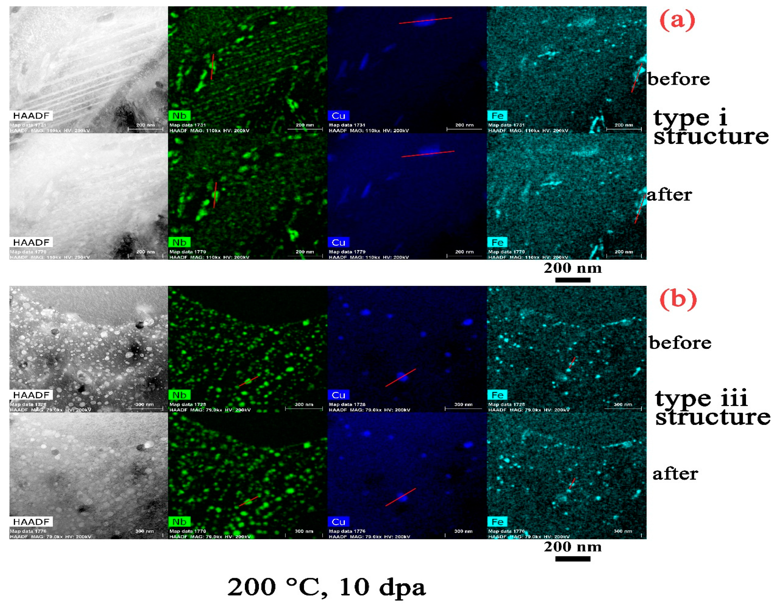
Figure 2, Figure 3, Figure 4 and Figure 5 present a comparison of the microstructure and alloying element distribution at the same location before and after heavy ion irradiation to 10 dpa at a constant temperature of 100 °C to 500 °C, depending on sample. The intermetallic precipitates have quite different responses to irradiation in terms of the precipitate structure, morphology, and composition and are categorized accordingly.
3.1. Zr2Cu
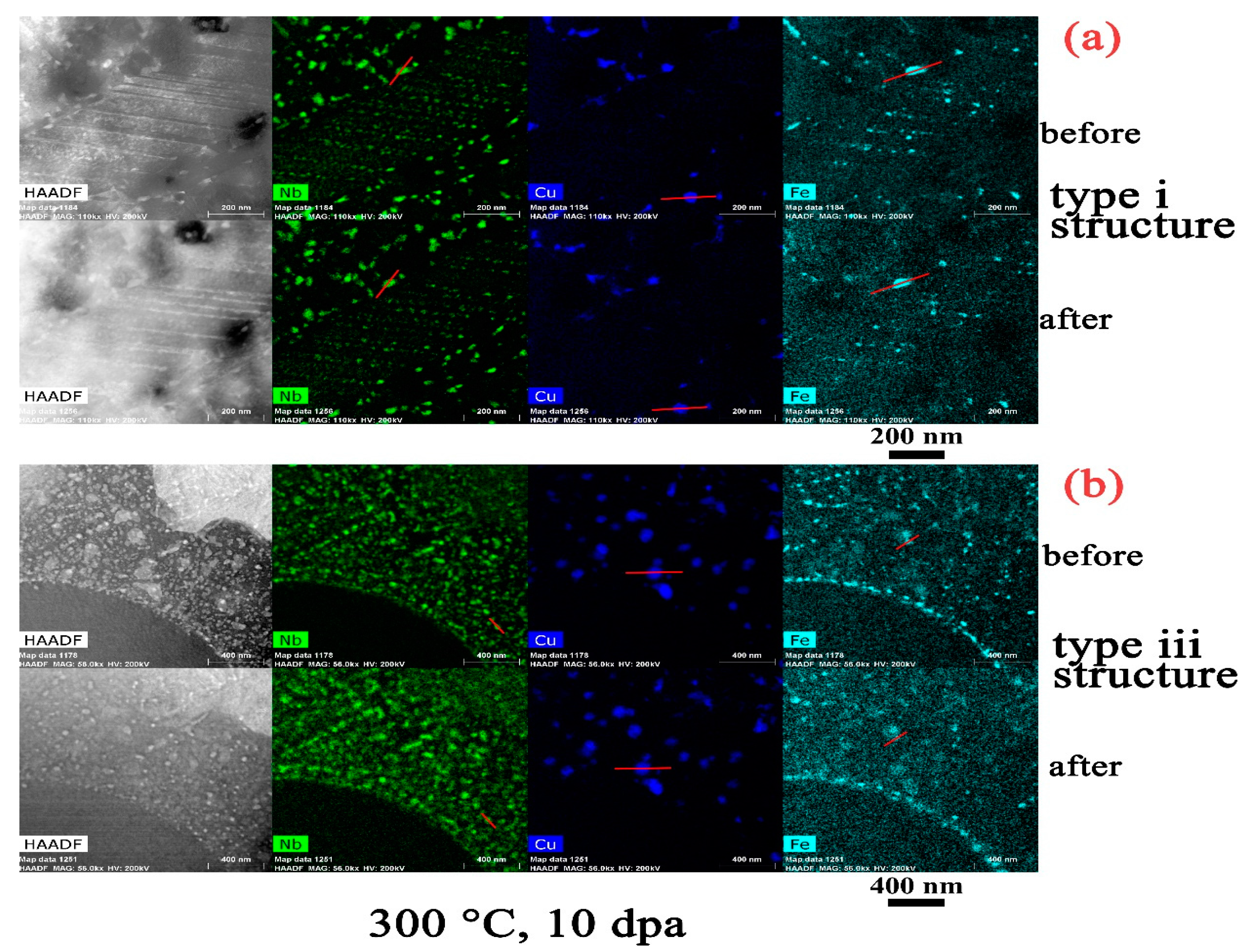
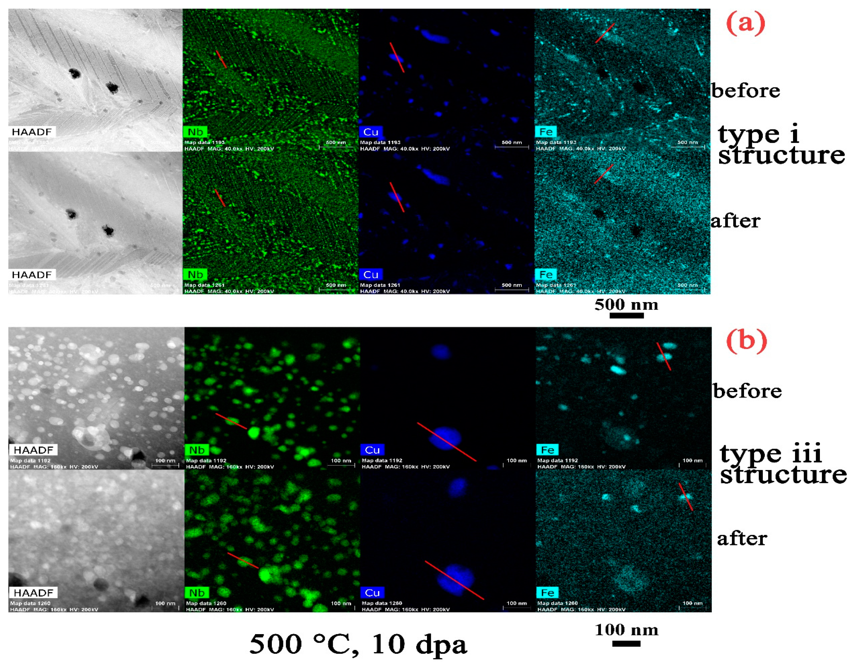
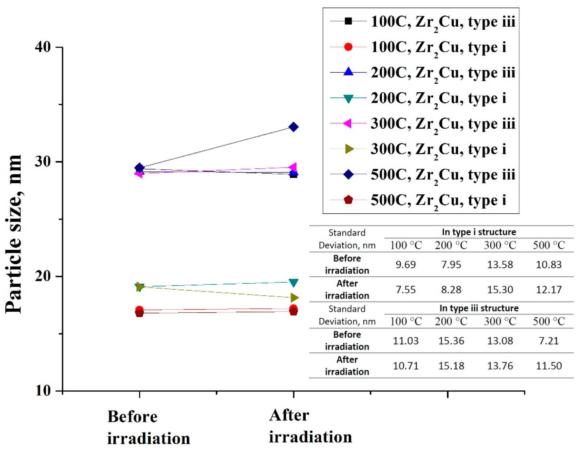
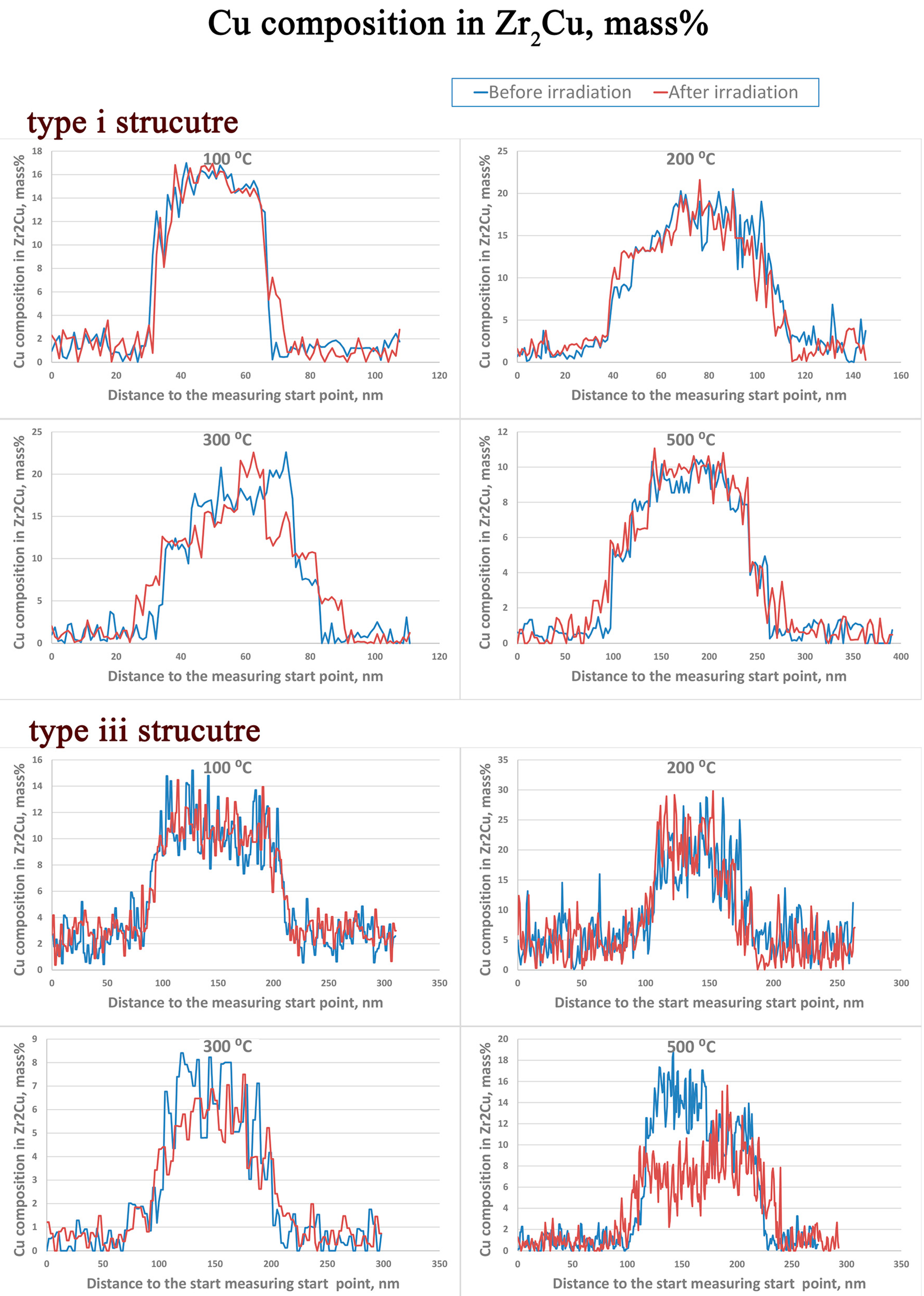
Figure 6 shows the bright field images and the corresponding electron diffraction patterns of the α–Zr matrix and Zr2Cu precipitates after irradiation at three different temperatures. By comparison of the electron diffraction patterns between the α–Zr and Zr2Cu precipitates, it is clear that the diffuse ring patterns at 100 °C and 200 °C are from the Zr2Cu precipitates. An amorphous ring is not observed at 300 °C. Therefore the irradiation induced crystalline to amorphous transformation temperature at this dose rate is between 200 °C and 300 °C. Few changes in the microstructure and composition of the Zr2Cu precipitates are observed at low irradiation temperatures (100 °C (Figure 2) and 200 °C (Figure 3)), excepting the radiation-induced amorphization. However when the temperature is increased to 300 °C (Figure 4) and 500 °C (Figure 5), there are obvious morphological and microchemical changes after irradiation. After irradiation at 500 °C, there is an apparent increase of Zr2Cu particle size in the type iii structure (Figure 5b). However, such changes are not observed in the type i structure (Figure 5a). The size of the Zr2Cu particles before and after irradiation is presented in Figure 7; the standard deviation of the measurement is not shown along with the plot but inserted as a chart in the figure for clarity (note that this ‘standard deviation’ is not an uncertainty in the measurement but rather is the width of the size distribution). Initially, no size change at 100 °C, 200 °C, or 300°C is seen in either type i or type iii structures. A slight growth of particles is detected at 500 °C in the type iii structure, while it is relatively constant in the type i structure. Irradiation-induced Cu redistribution is detected. Figure 8 shows a comparison of the Cu alloying element concentration in the same specific Zr2Cu precipitate before and after irradiation. The particles used for this measurement are indicated in the Cu maps of Figure 2, Figure 3 and Figure 4 by red lines (noting that the other three lines are very close to the drawn line). In type i structures, the dissolution and redistribution of Cu is not significant, which is consistent with the very limited size change in this type of structure. However, conspicuous compositional redistribution of Cu is noticed in the type iii structure at 500 °C; we see dissolution of Cu from the center regions of the Zr2Cu particles and redistribution to the peripheries. Due to the low solubility of Cu in Zr, it is likely re-precipitating at the new locations. By comparing the compositional changes of Cu in type i and type iii structures, it is thus noteworthy that the microstructure has a significant impact on the element redistribution during irradiation, especially at high irradiation temperatures. The type i structure is the Widmanstätten structure, consisting of α–phase platelets organized into basket-weave tangles, many of which are internally twinned, whereas the type iii structure is α–Zr grains with evenly dispersed intermetallic precipitates. Therefore, the differences in Cu redistribution under irradiation in distinct microstructures are related to the differences in irradiation damage accumulation in the different microstructures arising; for example, due to increased densities of grain boundaries, which act as point defect sinks.
3.2. β–Nb
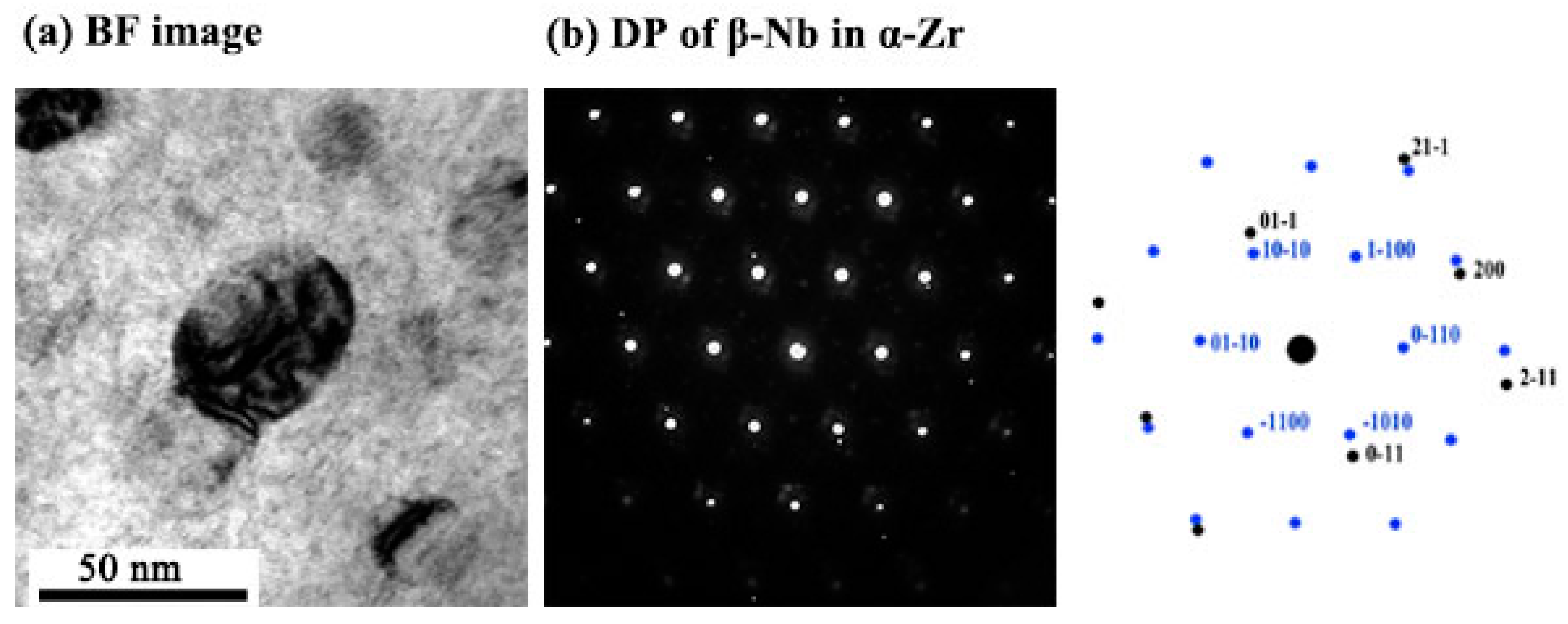
At all studied irradiation temperatures, a crystalline-to-amorphous transition of β–Nb does not take place, even after irradiation to 10 dpa. Figure 9 shows the bright field image and diffraction pattern of the β–Nb in α–Zr matrix at 100 °C after irradiation. Those maps clearly show that the β–Nb does not become amorphous even with the irradiation temperature as low as 100 °C and to such a high irradiation dose, which is in agreement with the observation in M5 (Zr–1.0Nb–0.1O) by Gilbon et al. [22], where the β–Nb particles were shown to remain fully crystalline under neutron irradiation at 280 °C and 350 °C to doses of about 3.5 dpa and 6.5 dpa.
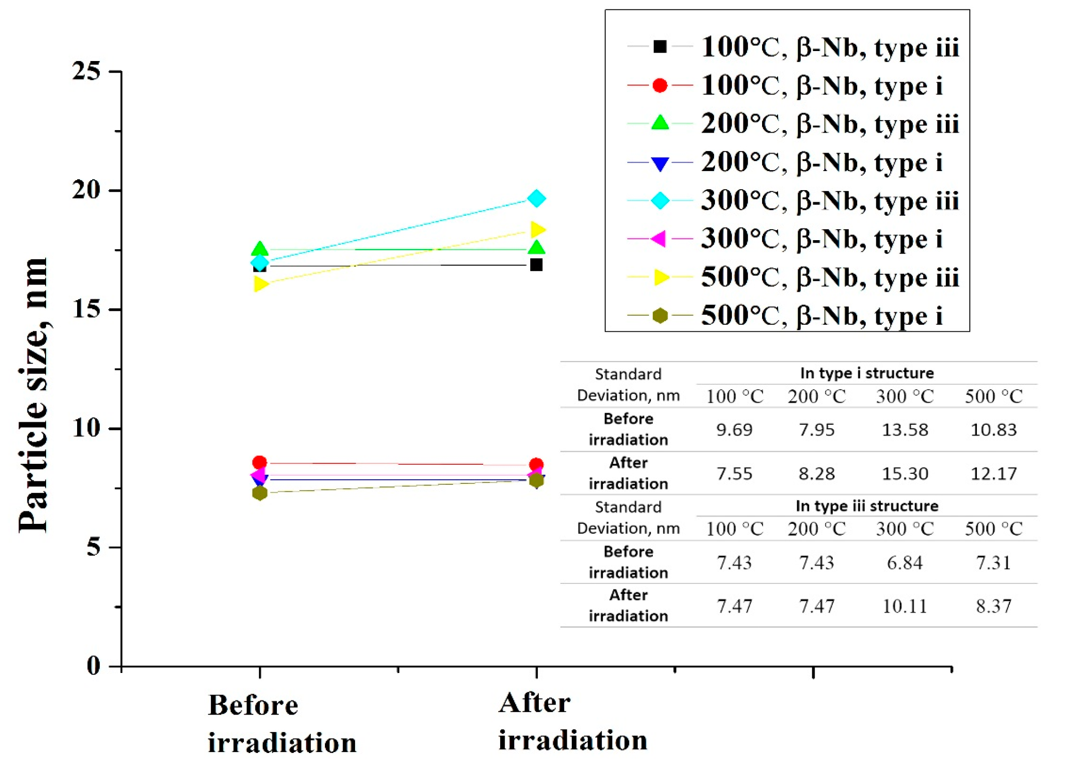
As can be seen in Figure 4 and Figure 5, there is an apparent increase in the β–Nb precipitate size at 300 °C and 500 °C irradiation temperatures in the type iii structure, while, in the type i structure, no particle growth is noticeable. To more clearly quantify the size change of β–Nb before and after irradiation, a map is presented in Figure 10. In the type iii structure, the increase of the precipitate size starts at 300 °C, and a higher irradiation temperature of 500 °C results in a similar increase in particle size. In contrast, in the type i structure, the precipitate size is comparatively constant at around 7 nm at all temperatures except at 500 °C, where perhaps a slight size increase occurs. In some previous reports [23,24], the precipitation of the Nb–rich β phase was observed at irradiation temperatures of 300 °C and 500 °C in α–Zr grains of Zr–2.5Nb pressure tubes by neutron and proton irradiation, respectively. The precipitation of neither β–Nb nor β–Zr is observable in our study. The reason for this is assumed to be related to the microstructure state of the material, i.e., many early researchers were working on the material in which the α–phase contains Nb in supersaturated solid solution (about 0.5–1 wt % Nb) in the as–fabricated condition [23]. The irradiation created cascade would then facilitate the diffusion and precipitation of the β phase. On the other hand, in our material, the α–grains are fully recrystallized and are thought to be in or close to the equilibrium state. Though the type i structure is a martensitic structure, which has a tendency to move towards the equilibrium state through recrystallization and precipitation, the abundant boundaries make the formation of irradiation damage structures unfavorable because of the significant absorption of defects by the boundaries, assisting recombination between interstitials and vacancies [25].
Figure 11 displays a measurement of the Nb concentration in β–Nb precipitates before and after heavy ion irradiation at the same location. The particles used for this measurement are indicated in the Nb maps of Figure 2, Figure 3 and Figure 4 by red lines. In the type i structure, there is no significant redistribution of Nb after irradiation from 100 °C to 300 °C, but, at the temperature of 500 °C, there is apparent redistribution, with a depletion of Nb from the center towards the surrounding matrix. In the type iii structure, the redistribution of Nb is noticed even after irradiation at 200 °C, and it becomes more conspicuous at 300 °C and 500 °C. Similar to the irradiation effect on Cu redistribution in Zr2Cu precipitates, the obvious redistribution of Nb is in agreement with the trend of the size change; size is relatively constant in the type i structure but increases in the type iii structure at higher temperatures.
3.3. Zr2Fe
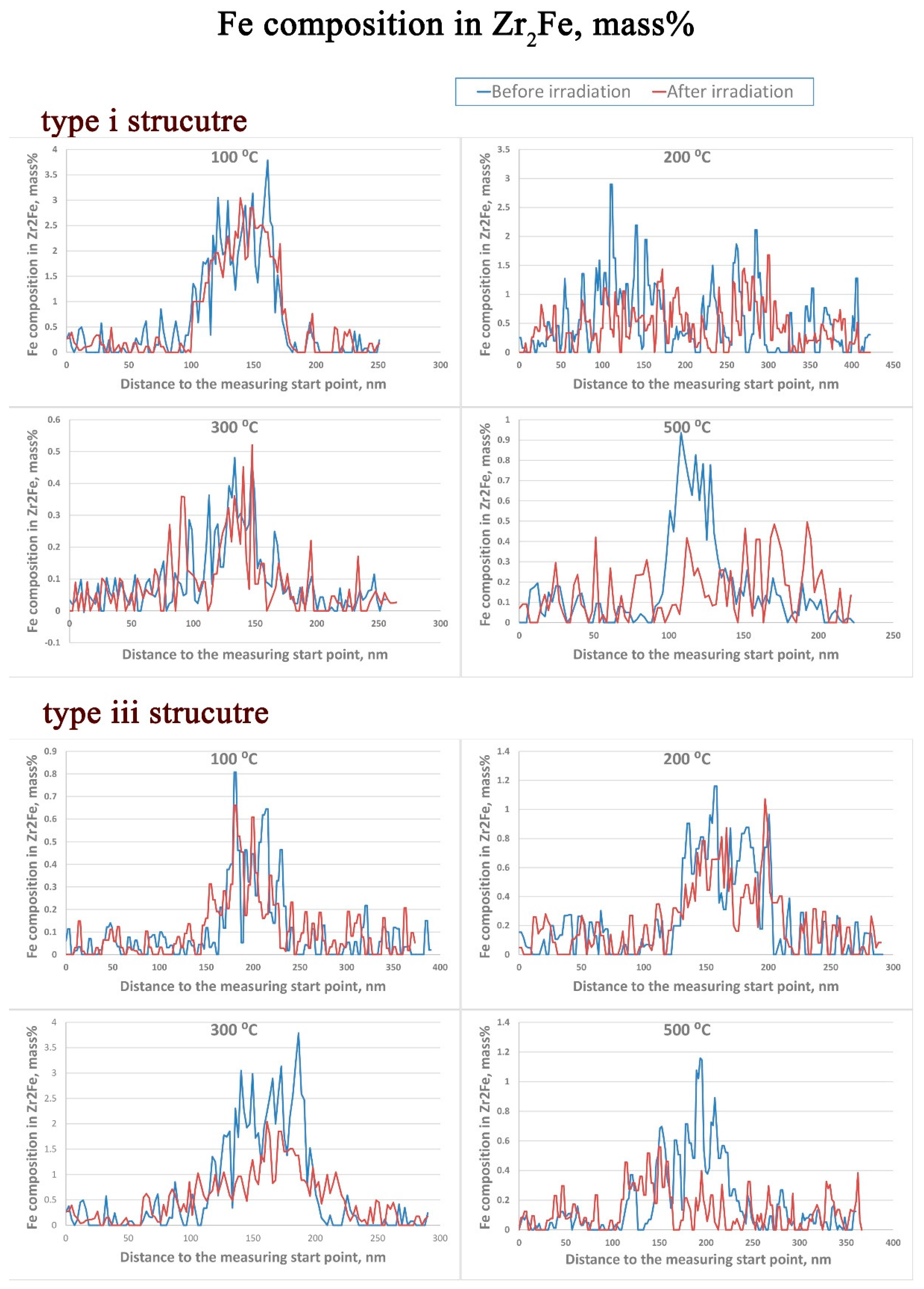
In Zr–2.5Nb–0.5Cu alloys, the Zr2Fe precipitates are few and small compared with the other two types of particles, which makes the determination of any amorphous transformation of the Zr2(Nb,Fe) hard. From Figure 2, Figure 3, Figure 4 and Figure 5 we can see that, at temperatures of 300 °C and below, the Zr2Fe phase appears to be very stable in the type i structure, but, in the type iii structure, an obvious depletion of Fe is observed at temperatures of 300 °C and 500 °C. The corresponding alloying element compositional changes of Fe before and after irradiation in the same particles are shown in Figure 12. The particles used for this measurement are indicated in the Fe maps of Figure 2, Figure 3 and Figure 4 by red lines. In the type i structure, an apparent depletion of Fe into the α-phase matrix is noticed at 500 °C, while, in the type iii structure, such depletion of Fe from the precipitates starts as early as 300 °C.
4. Discussion
4.1. Amorphization of Precipitates
Amorphization occurs when the balance between the rate of damage production (redistribution of atoms) exceeds the rate of thermal recombination towards the equilibrium crystalline phase. It has been demonstrated by many previous works [1,2,4,26,27,28] that the crystalline to amorphous transformation for a particular intermetallic precipitate is dependent on temperature, flux, and fluence. In the current investigation, the bombardment flux and total dose are fixed to 1 × 10⁻³ dpa/s and 10 dpa, respectively, which means that, within our study, only changes in the contribution from thermal annealing are being investigated as influencing the amorphous transformation. At lower temperatures, the defects produced by irradiation are relatively immobile with little thermal recovery, resulting in a greater defect retained concentration and a high degree of short-range disorder [28]. It is found that the critical amorphous transformation temperature for Zr2Cu is between 200 °C and 300 °C under these heavy ion irradiation conditions. Nagase and Umakoshi [29] reported that the Zr2Cu phase became amorphous at room temperature and is crystalline at 320 °C under electron irradiation in a melt-spun Zr66.7Cu33.3 alloy; this is lower than the transformation temperature of 200 °C in our study. Such difference is also found in Zr(Fe,Cr)2 and Zr2(Fe,Ni) precipitates in Zircaloy–2 and Zircaloy–4 [1,2,4], where electron, neutron, and Ar+ irradiation are used. Normally, the critical transformation temperature for electron irradiation is expected to be much lower than that for ion irradiation because the electron irradiation produces Frenkel pairs, hence chemical disorder is homogeneously distributed in the intermetallic precipitate, while ion irradiation produces point defects clustered in collision cascades [4].
For the distinct types of precipitates, the responses to irradiation are rather different. A crystalline to amorphous transformation is not observed in β–Nb. The propensity for amorphization for distinct precipitates is generally governed by two factors; the nature of atomic bonding and the tolerance for compositional variation [4,30]. The stronger the bonding, the more resistant it is to amorphous transformation. The relative strength of the atomic interactions can be correlated to the melting temperature of the compounds. The melting temperatures for Zr2Cu and β–Nb in Zr–2.5Nb are 1000 °C and 1850 °C, respectively [31,32]. Thus the β–Nb can be expected to be less likely to experience amorphous transformation, considering its relative bonding strength. In addition, the β–Nb can withstand a widely varying composition, around 10% Nb [31], which gives the β–Nb precipitates a great capacity to accept irradiation-induced deviation from stoichiometry [30].
4.2. Effect of Structure on the Precipitate Stability
It is very noticeable that the precipitate stability varies in different types of microstructures under irradiation. In the type i structure, the precipitates are relatively stable, while, in the type iii structure, the precipitate size increases dramatically at elevated temperatures. In addition to the size change, the compositional change is more obvious in type iii than in type i structures. For example we noticed the redistribution of Cu in Zr2Cu, Nb in β–Nb, and Fe in Zr2Fe in type iii structures at a relatively lower temperature than that in type i structures. To our knowledge, this is the first time the direct dependence of precipitate stability on the surrounding matrix microstructure has been reported. The zirconium alloys used in early studies such as Zircaloy–2 [1,2,3,26], Zircaloy–4 [1,26,27], Zr-2.5Nb [5,7,24,33], and HANA (high performance alloy for nuclear applications) [34] are all in the recrystallized state and do not exhibit martensitic structures. The main differences between type i and type iii structures are the amount of boundaries. Grain boundaries (GBs), or twin boundaries acting as net sinks for irradiation induced defects, have been observed in many metals such as Cu [35,36,37,38,39], Fe [40,41], Ni [42], and Zr [25,43], even though their sink strength is slightly different in the two cases. Singh et al. [44], in a study on austenitic stainless steels, recognized that radiation–induced damage decreases with grain size because of defect trapping at GBs. Griffith et al. [25] showed that the grain boundaries can be very effective sinks for interstitial point defects in Zr and Zr alloys. A recent in situ study carried out by Chen et al. [37] on nanotwinned Cu revealed that the twin boundaries can effectively remove a large number of defect clusters. In the type i structure, the precipitates are mainly distributed in the boundaries, including grain boundaries, martensite plate boundaries, and twin boundaries. Those boundaries serve as very good sinks for irradiation induced defects. The defects produced by irradiation are expected to enhance the solute diffusion rate due to the increase of solute solubility and a faster diffusion channel. Nuttall et al. [7] found an enhancement of solute diffusion rates in Zr–2.5Nb by irradiation, which exceeds the thermal diffusion rate by several orders of magnitude. Similar observations were reported by Motta et al. [45] in the same alloy. Therefore, the reduced diffusion rates will mean that irradiation induced alloying element redistribution is significantly restricted in type i compared to type iii structures.
Since our experiments were carried out in thin TEM foils, there is a question as to whether thin samples can represent the behavior of thick or ‘bulk’ samples. In TEM thin foils, the two free surfaces would have some effect on the defect formation/migration and the diffusion of alloying elements. Some studies have showed that a defect free layer may exist near the free surfaces and that this layer can be as large as three times the defect size, due to the existence of image forces [46,47]. Therefore, the defects in thin and thick samples can be expected to be different. However, for fast heavy ion irradiation, no difference was observed in a recent study in W [48], likely because the defect size is generally small in heavy ion irradiation. Our irradiation was carried out using rapid heavy ion irradiation conditions (around 10 min for 1 dpa). Therefore, it is likely that the surface effect will not be very strong. In addition, alloying element diffusion rates and microstructural changes have been found to be much slower in TEM thin foils compared to those in bulk samples in Zr alloys [49]. For the current study, all the investigated temperatures are below temperature/time combinations at which significant microstructural changes will occur. Therefore, the difference between thin and thick samples is small. In summary, we believe that, for this study, the results obtained from TEM thin films represent a reasonable emulation of the processes occurring in bulk materials.
5. Conclusions
The stability of precipitates in a Zr–2.5Nb–0.5Cu alloy under heavy irradiation is investigated. The major findings are as follows:
- (1)
- The amorphization of Zr2Cu is found under irradiation to 10 dpa, and its transformation temperature is found to be between 200 °C to 300 °C, whereas amorphization of β–Nb is not detected at any temperature, including as low as 100 °C.
- (2)
- The surrounding microstructure has significant effects on the precipitate stability. The precipitates are much more stable in microstructures with multiple boundaries than in coarse grain microstructures.
- (3)
- There is an apparent increase of the precipitate size for Zr2Cu in the type iii structure at a temperature of 500 °C, while a size change in the type i structure or at lower irradiation temperatures in the type iii structure is not detected. This size change is in accordance with the measured redistribution of Cu in Zr2Cu.
- (4)
- The redistribution of Nb in β–Nb and the depletion of Fe from Zr2Fe are detected at 300 °C and above in the type iii structure, but such irradiation induced alloying element redistribution only starts at 500 °C in the type i structure.
Acknowledgments
Financial support for this work came from a NSERC-UNENE Collaborative Research and Development (CRD) project and the NSERC/UNENE/Nu–Tech Precision Metals Industrial Research Chair Program at Queen’s University. The heavy ion irradiation was accomplished at Argonne National Laboratory, a US Department Office of Science Laboratory under Contract No. DE-AC02-06CH11357 managed by University of Chicago.
Author Contributions
Qingshan Dong, Zhongwen Yao, and Mark R. Daymond conceived and designed the experiments; Qingshan Dong, Zhongwen Yao, Qiang Wang, Hongbing Yu, and Mark A. Kirk performed the experiments; and Qingshan Dong analyzed the data and wrote the paper with contributions from Zhongwen Yao and Mark R. Daymond.
Conflicts of Interest
The authors declare no conflict of interest.
References
- Griffiths, M.; Gilbert, R.W.; Carpenter, G.J.C. Phase instability, decomposition and redistribution of intermetallic precipitates in Zircaloy–2 and –4 during neutron irradiation. J. Nucl. Mater. 1987, 150, 53–66. [Google Scholar] [CrossRef]
- Etoh, Y.; Shimada, S. Neutron irradiation effects on intermetallic precipitates in Zircaloy as a function of fluence. J. Nucl. Mater. 1993, 200, 59–69. [Google Scholar] [CrossRef]
- Kruger, R.M.; Adamson, R.B. Precipitate behavior in zirconium-based alloys in BWRs. J. Nucl. Mater. 1993, 205, 242–250. [Google Scholar] [CrossRef]
- Pêcheur, D.; Lefebvre, F.; Motta, A.T.; Lemaignan, C.; Charquet, D. Effect of irradiation on the precipitate stability in Zr alloys. J. Nucl. Mater. 1993, 205, 445–451. [Google Scholar] [CrossRef]
- Perovic, V.; Perovic, A.; Weatherly, G.C.; Purdy, G.R. The distribution of Nb and Fe in a Zr–2.5 wt % Nb alloy, before and after irradiation. J. Nucl. Mater. 1995, 224, 93–102. [Google Scholar] [CrossRef]
- Francis, E.M.; Harte, A.; Frankel, P.; Haigh, S.J.; Jädernäs, D.; Romero, J.; Hallstadius, L.; Preuss, M. Iron redistribution in a zirconium alloy after neutron and proton irradiation studied by energy–dispersive X-ray spectroscopy (EDX) using an aberration-corrected (scanning) transmission electron microscope. J. Nucl. Mater. 2014, 454, 387–397. [Google Scholar] [CrossRef]
- Nuttall, K.; Faulkner, D. The effect of irradiation on the stability of precipitates in Zr–2.5 wt % Nb alloys. J. Nucl. Mater. 1977, 67, 131–139. [Google Scholar] [CrossRef]
- Sabol, G.P.; Comstock, R.J.; Weiner, R.A.; Larouere, P.; Stanutz, R.N. In-Reactor Corrosion Performance of ZIRLO and Zinealoy4. In Proceedings of the Zirconium in the Nuclear Industry: Tenth International Symposium, Baltimore, MD, USA, 21–24 June 1993; ASTM International: Philadelphia, PA, USA, 1994. [Google Scholar]
- Anada, H.; Nomoto, K.I.; Shida, Y. Corrosion behavior of Zircaloy–4 sheets produced under various hot-rolling and annealing conditions. In Proceedings of the Zirconium in the Nuclear Industry: Tenth International Symposium, Baltimore, MD, USA, 21–24 June 1993; ASTM International: Philadelphia, PA, USA, 1994. [Google Scholar]
- Jeong, Y.H.; Lee, K.O.; Kim, H.G. Correlation between microstructure and corrosion behavior of Zr–Nb binary alloy. J. Nucl. Mater. 2002, 302, 9–19. [Google Scholar] [CrossRef]
- Kim, H.G.; Jeong, Y.H.; Kim, T.H. Effect of isothermal annealing on the corrosion behavior of Zr–xNb alloys. J. Nucl. Mater. 2004, 326, 125–131. [Google Scholar] [CrossRef]
- Park, J.Y.; Choi, B.K.; Jeong, Y.H.; Jung, Y.H. Corrosion behavior of Zr alloys with a high Nb content. J. Nucl. Mater. 2005, 340, 237–246. [Google Scholar] [CrossRef]
- Griffiths, M.; Gilbert, R.W.; Fidleris, V. Accelerated Irradiation Growth of Zirconium Alloys. In Proceedings of the Zirconium in the Nuclear Industry: Eighth International Symposium, San Diego, CA, USA, 19–23 June 1988; ASTM International: Philadelphia, PA, USA, 1989. [Google Scholar]
- Holt, R.A. In-reactor deformation of cold-worked Zr–2.5Nb pressure tubes. J. Nucl. Mater. 2008, 372, 182–214. [Google Scholar] [CrossRef]
- Russell, K.C. Phase stability under irradiation. Prog. Mater. Sci. 1984, 28, 229–434. [Google Scholar] [CrossRef]
- King, A.D.; Hood, G.M.; Holt, R.A. Fe–enhancement of self-diffusion in α–Zr. J. Nucl. Mater. 1991, 185, 174–181. [Google Scholar] [CrossRef]
- Zhang, H.K.; Yao, Z.; Morin, G.; Griffiths, M. TEM characterization of in-reactor neutron irradiated CANDU spacer material Inconel X–750. J. Nucl. Mater. 2014, 451, 88–96. [Google Scholar] [CrossRef]
- Field, G.J.; Dunn, J.T.; Cheadle, B.A. Analysis of the Pressure Tube Failure at Pickering NGS “A” Unit 2 Nuclear Systems Department. Can. Metall. Q. 1985, 24, 181–188. [Google Scholar] [CrossRef]
- Coleman, C.E.; Gilbert, R.W.; Carpenter, G.J.C.; Wetherly, G.C. Precipitation in Zr–2.5 wt % Nb during neutron irradiation. In Proceedings of the Phase Stability during Irradiation Symposium, Pittsburgh, PA, USA, 5–9 October 1980; The Metallurgical Society of AIME: New York, NY, USA, 1981; pp. 587–599. [Google Scholar]
- Dong, Q.; Yu, H.; Yao, Z.; Long, F.; Balogh, L.; Daymond, M.R. Study of microstructure and precipitates of a Zr–2.5Nb–0.5Cu CANDU spacer material. J. Nucl. Mater. 2016, 481, 153–163. [Google Scholar] [CrossRef]
- Was, G.S. Fundamentals of Radiation Materials Science: Metals and Alloys; Springer: New York, NY, USA, 2007; p. 52. [Google Scholar]
- Gilbon, D.; Soniak, A.; Doriot, S.; Mardon, J.P. Irradiation Creep and Growth Behavior, and Microstructural Evolution of Advanced Zr–Base Alloys. In Proceedings of the Zirconium in the Nuclear Industry: Twelfth International Symposium, Toronto, ON, Canada, 15–18 June 1988; ASTM International: Philadelphia, PA, USA, 2000. [Google Scholar]
- Griffiths, M.; Müllejans, H. A TEM study of α–phase stability in Zr–2.5 Nb pressure tubes following neutron irradiation (A TEM study of α–phase stability). Micron 1995, 26, 555–557. [Google Scholar] [CrossRef]
- Cann, C.D.; So, C.B.; Styles, R.C.; Coleman, C.E. Precipitation in Zr–2.5Nb enhanced by proton irradiation. J. Nucl. Mater. 1993, 205, 267–272. [Google Scholar] [CrossRef]
- Griffiths, M.; Gilbert, R.W.; Coleman, C.E. Grain boundary sinks in neutron-irradiated Zr and Zr-alloys. J. Nucl. Mater. 1988, 159, 405–416. [Google Scholar] [CrossRef]
- Yang, W.J.S.; Tucker, R.P.; Cheng, B.; Adamson, R.B. Precipitates in zircaloy: Identification and the effects of irradiation and thermal treatment. J. Nucl. Mater. 1986, 138, 185–195. [Google Scholar] [CrossRef]
- Yang, W.J.S. Precipitate stability in neutron-irradiated Zircaloy–4. J. Nucl. Mater. 1988, 158, 71–80. [Google Scholar] [CrossRef]
- Motta, A.T.; Howe, L.M.; Okamoto, P.R. Amorphization kinetics of Zr3Fe under electron irradiation. J. Nucl. Mater. 1993, 205, 258–266. [Google Scholar] [CrossRef]
- Nagase, T.; Umakoshi, Y. Phase stability of amorphous and crystalline phases in melt-spun Zr66.7Cu33.3 alloy under electron irradiation. Scr. Mater. 2003, 48, 1237–1242. [Google Scholar] [CrossRef]
- Brimhall, J.L.; Kissinger, H.E.; Charlot, L.A. Amorphous phase formation in irradiated intermetallic compounds. Radiat. Eff. 1983, 77, 273–293. [Google Scholar] [CrossRef]
- Abriata, J.P.; Bolcich, J.C. The Nb–Zr (Niobium-Zirconium) system. Bull. Alloy Phase Diagr. 1982, 3, 34–44. [Google Scholar] [CrossRef]
- Arias, D.; Abriata, J.P. Cu–Zr (Copper–Zirconium). Bull. Alloy Phase Diagr. 1990, 11, 452–459. [Google Scholar] [CrossRef]
- Dey, G.K.; Singh, R.N.; Tewari, R.; Srivastava, D.; Banerjee, S. Metastability of the β–phase in Zr-rich Zr–Nb alloys. J. Nucl. Mater. 1995, 224, 146–157. [Google Scholar] [CrossRef]
- Jung, Y.I.; Lee, M.H.; Kim, H.G.; Park, J.Y.; Jeong, Y.H. Behavior of a recrystallization in HANA–4 and HANA-6 zirconium-based alloys. J. Alloys Compd. 2009, 479, 423–426. [Google Scholar] [CrossRef]
- Bai, X.M.; Voter, A.F.; Hoagland, R.G.; Nastasi, M.; Uberuaga, B.P. Efficient Annealing of Radiation Damage Near Grain Boundaries via Interstitial Emission. Science 2010, 327, 1631–1634. [Google Scholar] [CrossRef] [PubMed]
- Han, W.Z.; Demkowicz, M.J.; Fu, E.G.; Wang, Y.Q.; Misra, A. Effect of grain boundary character on sink efficiency. Acta Mater. 2012, 60, 6341–6351. [Google Scholar] [CrossRef]
- Chen, Y.; Li, J.; Yu, K.Y.; Wang, H.; Kirk, M.A.; Li, M.; Zhang, X. In situ studies on radiation tolerance of nanotwinned Cu. Acta Mater. 2016, 111, 148–156. [Google Scholar] [CrossRef]
- Shu, S.; Bellon, P.; Averback, R.S. Role of point-defect sinks on irradiation-induced compositional patterning in model binary alloys. Phys. Rev. B 2015, 91, 214107. [Google Scholar] [CrossRef]
- Zhang, X.; Shu, S.; Bellon, P.; Averback, R.S. Precipitate stability in Cu–Ag–W system under high-temperature irradiation. Acta Mater. 2015, 97, 348–356. [Google Scholar] [CrossRef]
- Di, C.; Wang, J.; Chen, T.; Shao, L. Defect annihilation at grain boundaries in alpha–Fe. Sci. Rep. 2013, 3, 1450. [Google Scholar]
- Song, M.; Wu, Y.D.; Chen, D.; Wang, X.M.; Sun, C.; Yu, K.Y.; Chen, Y.; Shao, L.; Yang, Y.; Hartwig, K.T.; et al. Response of equal channel angular extrusion processed ultrafine-grained T91 steel subjected to high temperature heavy ion irradiation. Acta Mater. 2014, 74, 285–295. [Google Scholar] [CrossRef]
- Sun, C.; Song, M.; Yu, K.Y.; Chen, Y.; Kirk, M.; Li, M.; Wang, H.; Zhang, X. In situ Evidence of Defect Cluster Absorption by Grain Boundaries in Kr Ion Irradiated Nanocrystalline Ni. Metall. Mater. Trans. A 2013, 44, 1966–1974. [Google Scholar] [CrossRef]
- Idrees, Y.; Yao, Z.; Kirk, M.A.; Daymond, M.R. In situ study of defect accumulation in zirconium under heavy ion irradiation. J. Nucl. Mater. 2013, 433, 95–107. [Google Scholar] [CrossRef]
- Singh, B.N.; Foreman, A.J.E. Calculated grain size-dependent vacancy supersaturation and its effect on void formation. Philos. Mag. 1974, 29, 847–858. [Google Scholar] [CrossRef]
- Motta, A.T.; Faldowski, J.A.; Howe, L.M.; Okamoto, P.R. In situ studies of phase transformations in zirconium alloys and compounds under irradiation. In Proceedings of the Zirconium in the Nuclear Industry: Eleventh International Symposium, Garmisch-Partenkirchen, Germany, 11–14 September 1995; ASTM International: Philadelphia, PA, USA, 1996. [Google Scholar]
- Baštecká, J. Interaction of dislocation loop with free surface. Cechoslovackij Fiziceskij Zurnal B 1964, 14, 430–442. [Google Scholar] [CrossRef]
- Narayan, J.; Washburn, J. Stability of dislocation loops near a free surface. J. Appl. Phys. 1972, 43, 4862–4865. [Google Scholar] [CrossRef]
- Yi, X.; Jenkins, M.L.; Hattar, K.; Edmondson, P.D.; Roberts, S.G. Characterisation of radiation damage in W and W-based alloys from 2 MeV self-ion near-bulk implantations. Acta Mater. 2015, 92, 163–177. [Google Scholar] [CrossRef]
- Dong, Q.; Yu, H.; Qin, H.; Yao, Z.; Daymond, M.R. A direct comparison of annealing in TEM thin foils and bulk material in a zirconium alloy. To be submitted.
Figure 1.
(a) SEM and (b) TEM bright field maps showing the three types of microstructure of the as-received material.
Figure 1.
(a) SEM and (b) TEM bright field maps showing the three types of microstructure of the as-received material.
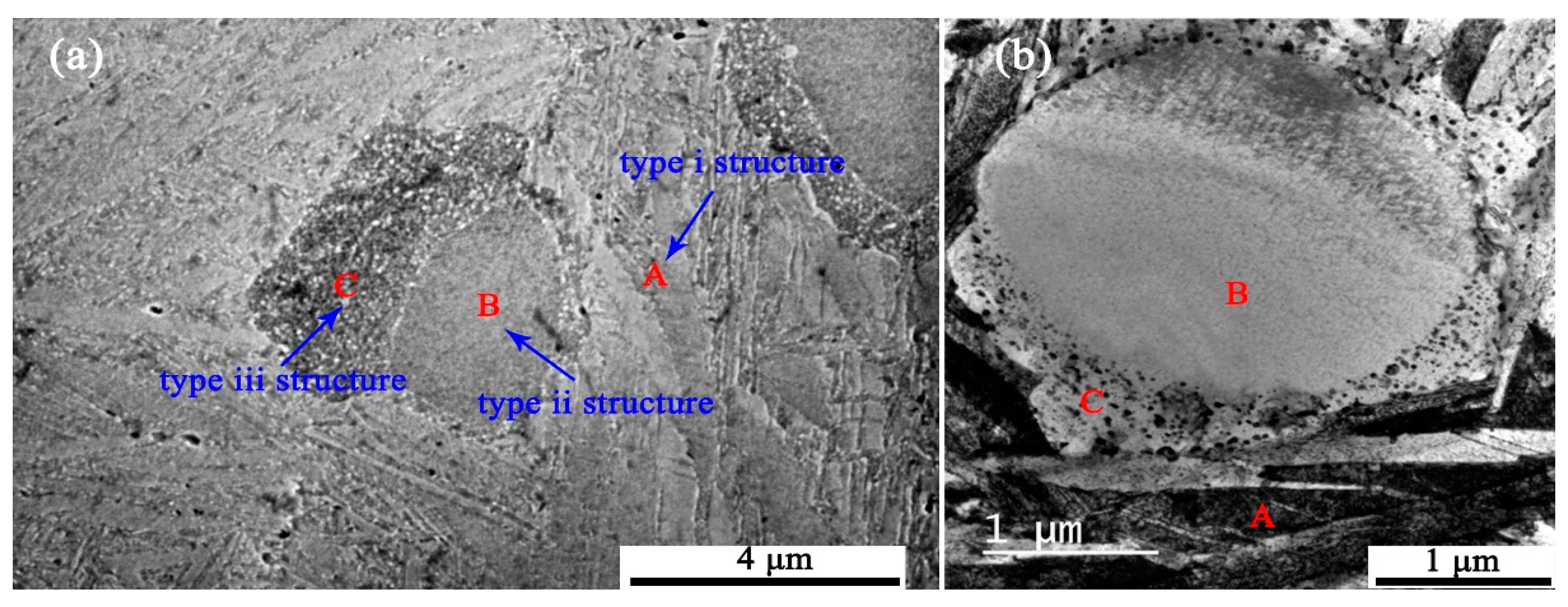
Figure 2.
HAADF (High-angle annular dark-field) and Chemi-STEM micrographs showing the distribution of Nb, Cu, and Fe alloying elements before and after heavy ion irradiation at 100 °C to 10 dpa in (a) type i and (b) type iii structures. Red lines in the maps indicate the precipitates used for the element distribution line profile measurement.
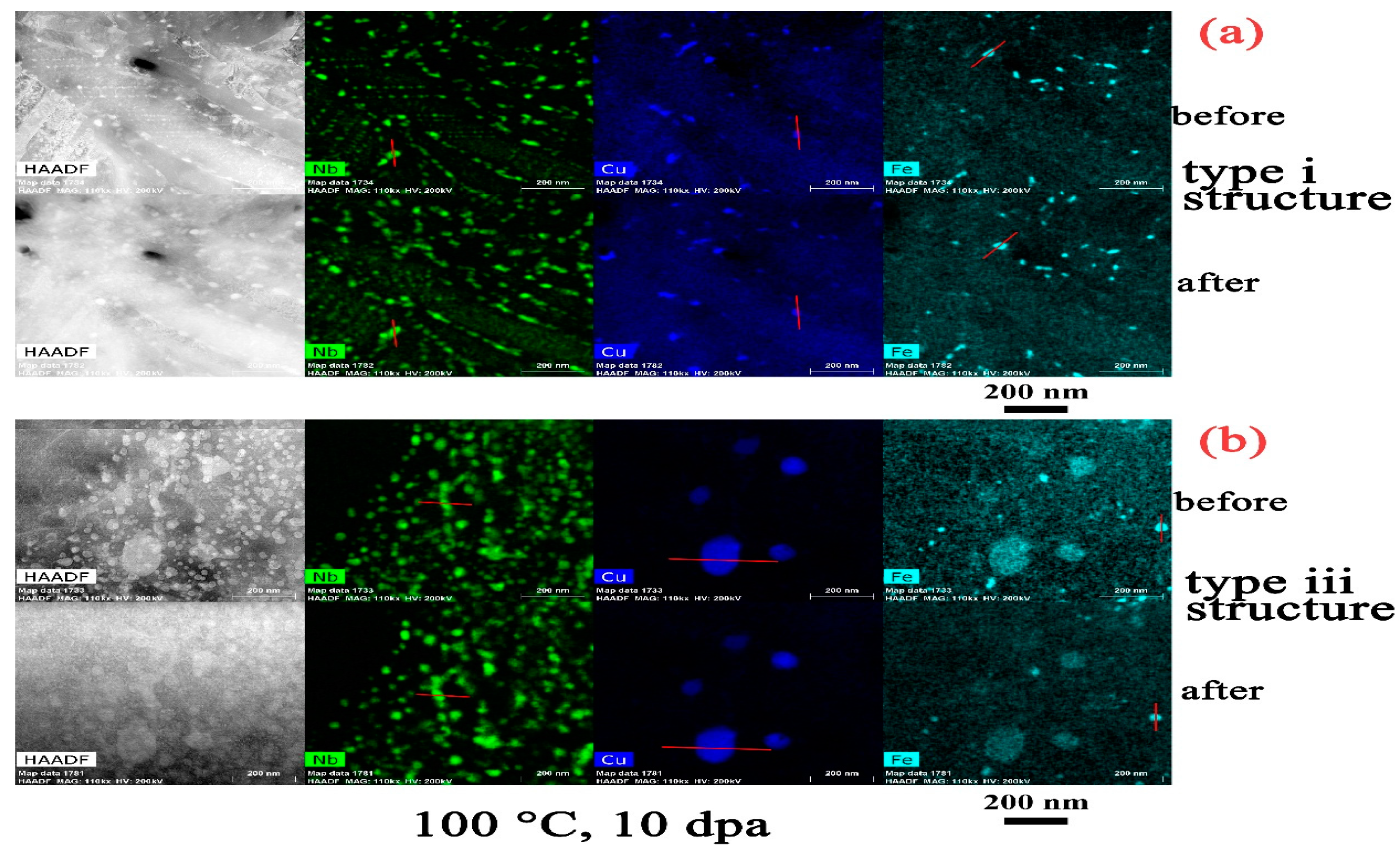
Figure 3.
HAADF and Chemi-STEM micrographs showing the distribution of Nb, Cu, and Fe alloying elements before and after heavy ion irradiation at 200 °C to 10 dpa in (a) type i and (b) type iii structures. Red lines in the maps indicate the precipitates used for the element distribution line profile measurement.

Figure 4.
HAADF and Chemi-STEM micrographs showing the distribution of Nb, Cu, and Fe alloying elements before and after heavy ion irradiation at 300 °C to 10 dpa in (a) type i and (b) type iii structures. Red lines in the maps indicate the precipitates used for the element distribution line profile measurement.

Figure 5.
HAADF and Chemi-STEM micrographs showing the distribution of Nb, Cu, and Fe alloying elements before and after heavy ion irradiation at 500 °C to 10 dpa in (a) type i and (b) type iii structures. Red lines in the maps indicate the precipitates used for the element distribution line profile measurement.

Figure 6.
The (a) bright field images, (b) selective area diffraction patterns of α–Zr grains, and (c) Zr2Cu in α–Zr at 100 °C, 200 °C, and 300 °C after irradiation showing the amorphous transformation in Zr2Cu under heavy ion irradiation to 10 dpa. The diffraction patterns were taken at z (zone axis) = [0002] of α–Zr.
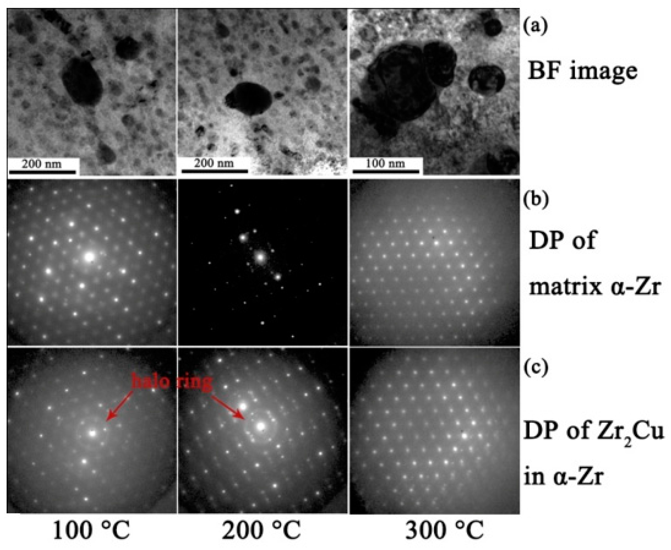
Figure 7.
The size of Zr2Cu precipitates in type i and iii structures before and after irradiation at 100 °C, 200 °C, 300 °C, and 500 °C, respectively. The standard deviation of the measurements is inserted in the right corner.
Figure 7.
The size of Zr2Cu precipitates in type i and iii structures before and after irradiation at 100 °C, 200 °C, 300 °C, and 500 °C, respectively. The standard deviation of the measurements is inserted in the right corner.

Figure 8.
The concentration change of Cu in Zr2Cu precipitates in type i and iii structures before and after irradiation at 100 °C, 200 °C, 300 °C, and 500 °C.
Figure 8.
The concentration change of Cu in Zr2Cu precipitates in type i and iii structures before and after irradiation at 100 °C, 200 °C, 300 °C, and 500 °C.

Figure 9.
(a) Bright field image and (b) diffraction pattern of β–Nb in α–Zr at 100 °C after irradiation showing no amorphization of β–Nb. The diffraction pattern was taken at z = [0002] of α–Zr.
Figure 9.
(a) Bright field image and (b) diffraction pattern of β–Nb in α–Zr at 100 °C after irradiation showing no amorphization of β–Nb. The diffraction pattern was taken at z = [0002] of α–Zr.

Figure 10.
The size of β–Nb precipitates in type i and iii structures before and after irradiation at 100 °C, 200 °C, 300 °C, and 500 °C. The standard deviation of the measurements is inserted in the right corner.
Figure 10.
The size of β–Nb precipitates in type i and iii structures before and after irradiation at 100 °C, 200 °C, 300 °C, and 500 °C. The standard deviation of the measurements is inserted in the right corner.

Figure 11.
The concentration change of Nb in β–Nb precipitates in type i and iii structures before and after irradiation at 100 °C, 200 °C, 300 °C, and 500 °C.
Figure 11.
The concentration change of Nb in β–Nb precipitates in type i and iii structures before and after irradiation at 100 °C, 200 °C, 300 °C, and 500 °C.
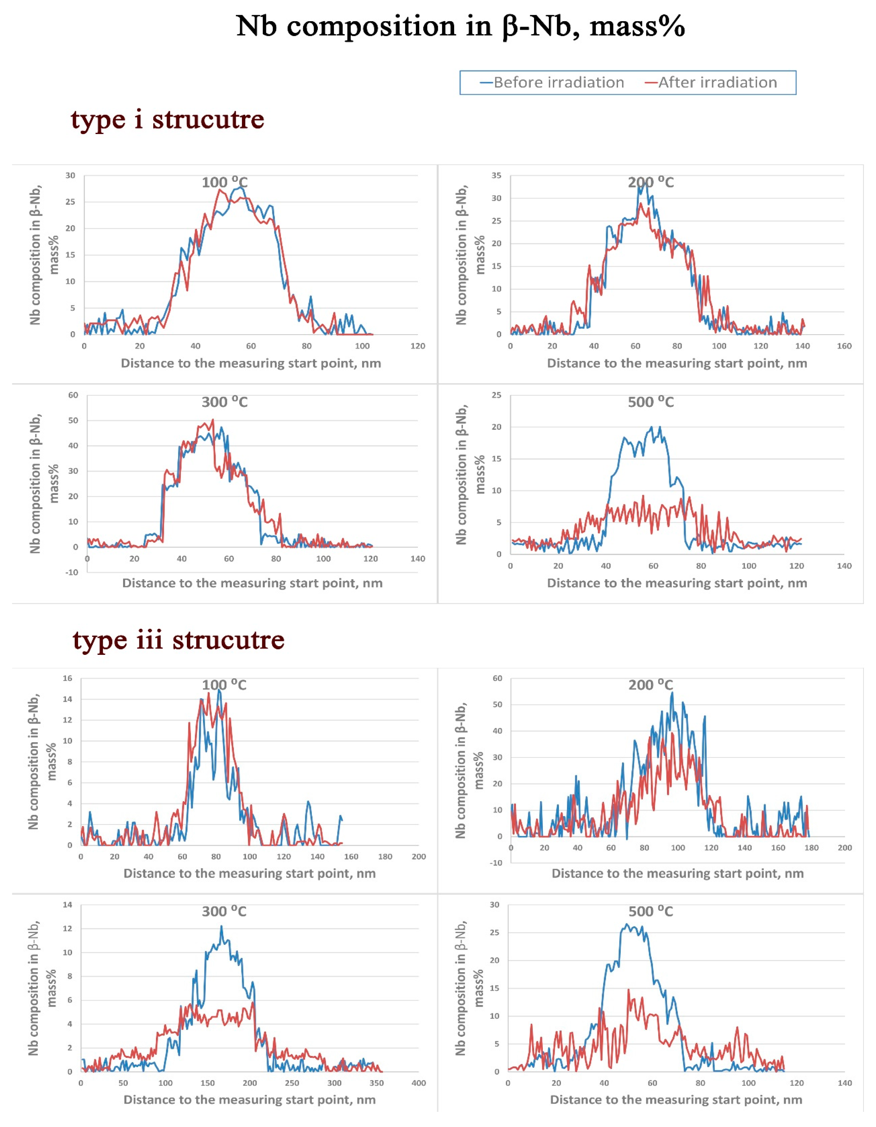
Figure 12.
The concentration change of Fe in Zr2Fe precipitates in type i and iii structures before and after irradiation at 100 °C, 200 °C, 300 °C, and 500 °C.
Figure 12.
The concentration change of Fe in Zr2Fe precipitates in type i and iii structures before and after irradiation at 100 °C, 200 °C, 300 °C, and 500 °C.
© 2017 by the authors. Licensee MDPI, Basel, Switzerland. This article is an open access article distributed under the terms and conditions of the Creative Commons Attribution (CC BY) license (http://creativecommons.org/licenses/by/4.0/).
Share and Cite
MDPI and ACS Style
Dong, Q.; Yao, Z.; Wang, Q.; Yu, H.; Kirk, M.A.; Daymond, M.R. Precipitate Stability in a Zr–2.5Nb–0.5Cu Alloy under Heavy Ion Irradiation. Metals 2017, 7, 287. https://doi.org/10.3390/met7080287
AMA Style
Dong Q, Yao Z, Wang Q, Yu H, Kirk MA, Daymond MR. Precipitate Stability in a Zr–2.5Nb–0.5Cu Alloy under Heavy Ion Irradiation. Metals. 2017; 7(8):287. https://doi.org/10.3390/met7080287
Chicago/Turabian StyleDong, Qingshan, Zhongwen Yao, Qiang Wang, Hongbing Yu, Mark A. Kirk, and Mark R. Daymond. 2017. "Precipitate Stability in a Zr–2.5Nb–0.5Cu Alloy under Heavy Ion Irradiation" Metals 7, no. 8: 287. https://doi.org/10.3390/met7080287
Note that from the first issue of 2016, this journal uses article numbers instead of page numbers. See further details here.