Article

Influence of Build Orientation, Heat Treatment, and Laser Power on the Hardness of Ti6Al4V Manufactured Using the DMLS Process

by
Anna Guzanová
1,*,
Gabriela Ižaríková
2,
Janette Brezinová
1,
Jozef Živčák
3,
Dagmar Draganovská
1 and
Radovan Hudák
3
1
Department of Mechanical Technology and Materials, Faculty of Mechanical Engineering, Technical University of Košice, 040 01 Košice, Slovakia
2
Department of Applied Mathematics and Informatics, Faculty of Mechanical Engineering, Technical University of Košice, 040 01 Košice, Slovakia
3
Department of Biomedical Engineering and Measurement, Faculty of Mechanical Engineering, Technical University of Košice, 040 01 Košice, Slovakia
*
Author to whom correspondence should be addressed.
Metals 2017, 7(8), 318; https://doi.org/10.3390/met7080318
Submission received: 20 July 2017 / Revised: 10 August 2017 / Accepted: 11 August 2017 / Published: 18 August 2017

Abstract

:
This contribution is focused on the influence of build orientation on hardness of materials sintered using direct metal laser sintering (DMLS) technology. It builds on the current research works that has monitored the influence of build orientation on a fatigue life, mechanical properties, roughness after machining, etc. In the mentioned work, a slight influence of build orientation on the above properties was shown. The hardness was measured on a Ti6Al4V alloy which was made of powder by DMLS technology. The individual materials were sintered at different laser powers, then annealed to remove internal stresses. Part of the experiment examined the metallographic analysis of materials in the direction perpendicular to the sintered layers and parallel with the sintered layers. Microhardness was measured on metallographic cross-sections and the results were statistically processed. The influence of laser power on a respective material hardness was assessed by one-way analysis of variance (ANOVA), a comparison of the hardness between sintered and sintered-annealed samples, as well as the comparison of hardness in the two considered directions was performed by t-test and F-test. A statistically significant difference in the hardness of the materials prepared at different laser powers was found. The influence of heat treatment, as well as the direction of material building also showed a statistically significant difference.

Graphical Abstract

1. Introduction

Rapidly expanding additive manufacturing (AM) methods have brought significant progress to the emerging industry over the last decade. They allow the production of metal parts of a complicated shape directly from a computer model, without time-consuming machining, assembly, or preparing expensive casting molds. The 3D printing process produces high strength, yet delicate, components that are used in many industries, including aerospace, automotive, electronics, packaging, and medicine.
In the area of biomedical engineering—implant production, replacement of various missing parts of the skeleton, etc.—the proven biocompatible Ti6Al4V alloy is widely implemented. Since each substitute possesses the unique shape and the number of pieces produced is in most cases only one, from an economic point of view classical production technologies are unusable. The only possible answer for these boundary conditions is additive manufacturing technology. The powder of Ti6Al4V alloy is most commonly processed by direct metal laser sintering (DMLS) and selective laser melting (SLM) [1,2,3,4,5,6,7,8,9,10,11].

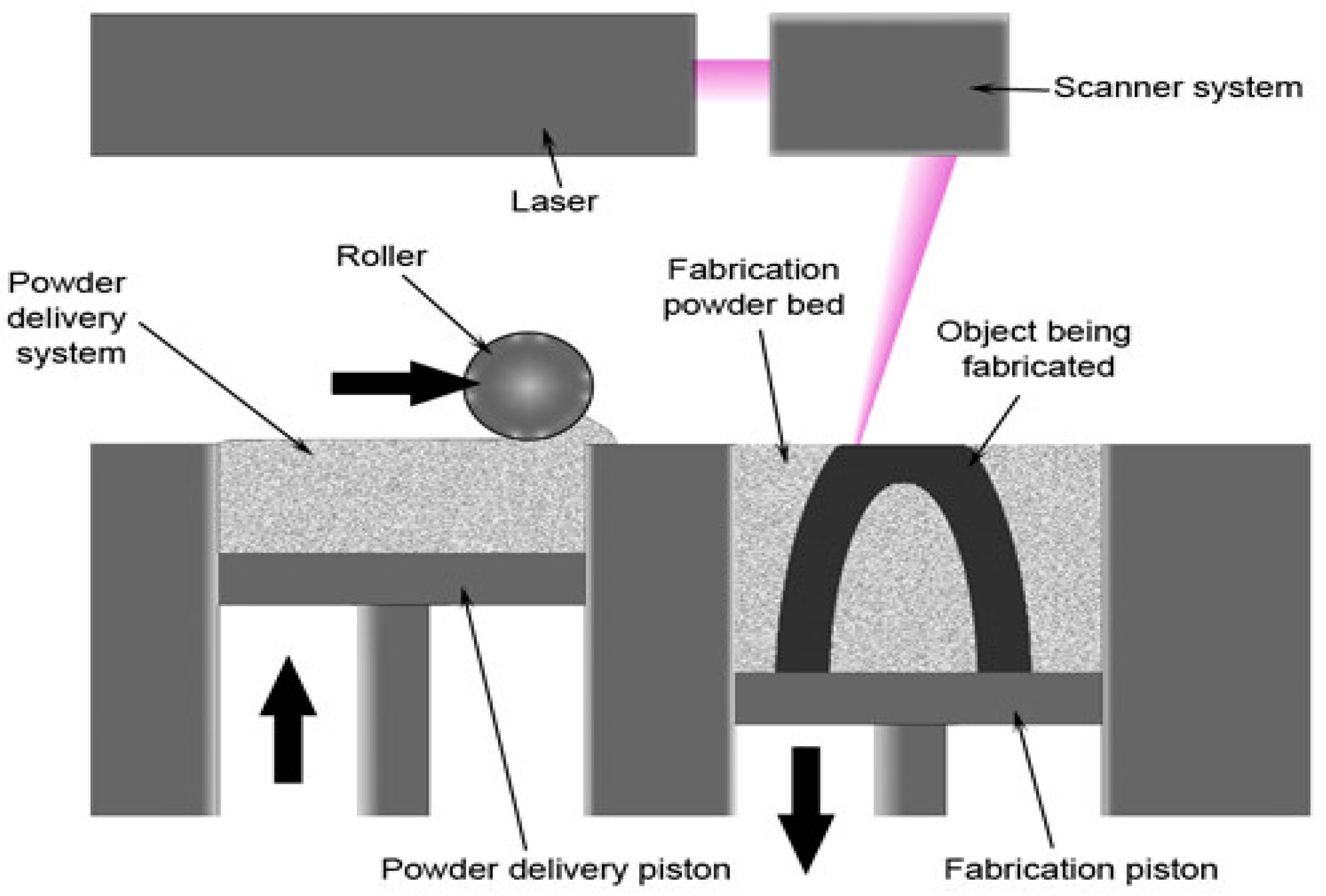
1.1. Direct Metal Laser Sintering (DMLS)

Direct Metal Laser Sintering is an additive manufacturing technique for metal 3D printing. It utilizes a laser as a power source in order to sinter metal powder by aiming a laser and tracing a cross section of the object layer by layer. The dosing device adjusts the amount of powder for one layer and the blade arm spreads a uniform layer of powder on the surface of the platform according to the selected layer thickness, Figure 1. At the point of impact of the laser beam, the metallic powder is locally melted, whereby the underlying layer is melted and then solidified. Each run partially overlaps the preceding run in order to form proper metallic bonds between the current layer and previous layers and, therefore, produces a homogeneous solid. Previously-solidified layers are re-melted and cooled several times at inconsistent levels of heat [12]. The platform also delivers heat, so the molten metal solidifies very quickly. For most materials, the working chamber is filled with a protective gas environment to protect the part from oxidation. The thickness of the one powder layer is 0.020 to 0.100 mm [12]. Due to the surface quality of the part being sintered, finishing operations are an essential part of the production process—removal of supports, blasting, machining, grinding, polishing, [13] etc. Sintered parts can contain some structure defects due to the tendency of the process to build an unbalanced stress profile into the part between the layers during processing. This is known as the residual stresses problem and it can cause crack initiation, delamination, and can reduce the fatigue strength of the part compared to bulk-formed parts [12]. The problem of porosity and large microstructure defects that can degrade tensile properties is solved by optimizing the DMLS parameters.
However, besides DMLS technology, there is the widely-used selective laser sintering (SLS) and selective laser melting (SLM) technologies, and the following question often arises: What is the difference between the processes of sintering and melting? Sintering processes do not fully melt the powder, but heat it to the point that the powder can fuse together on a molecular level. In laser melting a full melt of processed powder can be achieved—the powder is not merely fused together, but is actually melted into a homogenous part. Advanced machines for DMLS/SLM are able to both sinter or melt the powder, depending on the process settings and laser type [14]. According to the settings and laser type the following binding mechanisms can be achieved: solid state sintering, chemically-induced binding, liquid phase sintering, partial melting, and full melting [15].
Due to the principle of these additive technologies, it is possible to expect some differences in structure, mechanical, or fatigue properties with respect to the direction of building the part [16,17,18,19,20].

1.2. Research Activities Related to DMLS/SLM of Ti6Al4V

Many authors in the research are focused on the effects of Ti6Al4V processing technology on its mechanical, fatigue properties, surface quality after machining, and so on [20,21,22,23,24,25,26]. In particular, the influence of the building direction in additive technologies is observed.
Since, in laser sintering, Ti6Al4V powder is locally, and in SLM technology, completely, melted, in resulting structure can expect to have different structural phases (β, α, α′, and αm) depending on the thickness of the part and, hence, also the different cooling rates [27]. When cooling the Ti6Al4V melt, the phase changes appear according to the TTT (time-temperature transformation) diagram are shown, which can be seen in Figure 2.
In this sense, the DMLS or SLM process is, in part, similar to laser welding. Hong and Shin in [28] found that when welding the Ti6Al4V alloy, maximum hardness occurs at the fusion zone and HAZ (heat-affected zone) boundaries because of the high cooling rate. In addition, it has been found that the rate of laser welding has an effect on the formation of martensite and, hence, on the resulting hardness. To avoid a sharp increase in hardness at the weld edges, it is advisable to use lower welding power and lower weld speeds.
Li, in [29], found that different laser powers in SLM of commercially-pure titanium led to the different phase formation, microstructure, texture, and mechanical properties (the authors focused on compressive mechanical properties).
Mercelis, in [30], assessed residual stress in the parts produced using SLM and SLS technology. He found that the most important parameters determining the magnitude and shape of the residual stress profiles are the material properties, the sample and substrate height, the laser scanning strategy, and the heating conditions.
Kruth, in [15,31,32], found that in SLM, the process can be made following changes that reduce the high temperature gradient: using short scan vectors and preheating of the base plate can reduce the thermal stresses in a particular direction by the optimal choice of the orientation of the scan vectors. The change in thermal conditions affects the final properties of the product. Many works are also aimed on simulations of thermal conditions during additive laser processes, for example, Khairallah, in [14].
Raju, in [33], tested samples from a compact Ti6Al4V alloy covered with the same alloy by LMD (laser metal deposition) using different scanning speeds and, therefore, different cooling rates. It was found that LMD deposits of Ti6Al4V have a higher hardness compared to a compact base material. This is due to a ~50% decrease in the β phase relative concentration compared to the base material by transformation into a fine Widmanstätten α-colony. The fine Widmanstätten structure or martensite phase in the deposit has up to 20% higher microhardness compared to the base material. Thanks to the higher hardness, the layer applied increases the wear resistance of the material.
Milton, in his study [18], considered three different directions of building test samples produced by SLM technology. They examined the influence of the build direction on the resulting roughness after machining and compared it to the roughness of the compact hot rolled alloy. They found slight differences in hardness and, consequently, in roughness Ra relative to the build direction.
Konečná and Bača, in [17,19,34], studied the influence of the build direction in DMLS technology on the microstructure and fatigue. It has been found that the microstructure characteristics, such as pores, depend on the building process. The fatigue efficiency of the Ti6Al4V alloy depends on the the load direction relative to the build direction. The lowest fatigue strength was observed for samples loaded parallel to the build direction.
Weißmann, in [16], examined the mechanical properties of open porous structures with a different cell orientation against the load direction. It has been found that the elementary cell orientation affects the mechanical properties of the entire structure.
In the light of previously mentioned research works it is obvious that the parameters of additive technologies, together with the material used, geometry of the part, and the used sintering strategy significantly influence the thermal processes during sintering and, thus, the microstructure and mechanical properties of the final product. The inhomogeneity of the structure and mechanical properties resulting from different heat dissipation during layer cooling can be mitigated by heat treatment of the sintered products, as evidenced by the data from [35] where the basic mechanical properties differ depending on the direction, and also due to the heat treatment.
Therefore, the authors decided to contribute to the efforts of previous researchers and decided to map out several influences acting simultaneously: the influence of laser power, the build orientation, and the stress-relief annealing of Ti6Al4V alloy prepared by DMLS technology on mechanical properties, represented by the microhardness, using experimental and statistical tools.

2. Materials and Methods

2.1. Material

Ti6Al4V of grade 5 α-β alloy powder was used for sintering the test samples. The alloy always contains aluminum to stabilize the α phase and vanadium to stabilize the β phase. The two-phase microstructure typically consists of many lamellar colonies composed of varying needle layers and thin layers of β phase which cause good mechanical properties, such as high strength and good ductility. Table 1 shows the chemical composition and Table 2 shows the essential material characteristics of the material that meets the specifications of the standard ASTM F136. These specifications relate to the mechanical, chemical, and metallurgical properties of the Ti6Al4V alloy used in the manufacture of surgical implants [36].
The material is supplied as a powder and is made by gas atomization (in air, steam, N2, Ar, He). Figure 3 shows the Ti6Al4V powder used in DMLS technology.

2.2. DMLS Parameters

Test samples were made on an EOSINT M 280 sintering device (EOS—Electro Optical Systems, München, Germany). The datasheet on this sintering device can be found in [38]. A high-energy CO2 laser system (EOS—Electro Optical Systems, München, Germany) was used for sintering, according to a defined pattern, at various power levels: 150, 155, 160, 165, 170, 175, 180, 185, and 190 W. The laser speed was 1250 mmps, and the thickness of the layer was 0.03 mm. The powder was locally melted at the laser beam track and then solidified. The steel platform serves as a structural support and heat dissipation device during sintering. To protect from oxidation the process takes place in an argon atmosphere.

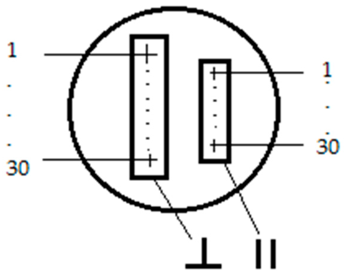
2.3. The Shape and Dimensions of the Test Samples

For experimental works test samples were made with dimensions of 20 mm × 20 mm × 2 mm. The samples differ in the power of the laser sintering and heat treatment: sintered, or sintered-annealed.

2.4. Heat Treatment of Materials

Half of the test samples were heat-treated (stress-relief annealing) after sintering. The annealing temperature was 850 °C, the dwell time was 2 h, in an argon atmosphere.

2.5. Metallographic Study of Materials

Metallographic analysis of sintered materials was performed in two directions, perpendicular and parallel to the sintered layers (Figure 4).
Metallographic samples were grinded on a set of abrasive papers, polished using polishing silica suspension and etched using Kroll’s reagent, for 5–10 s at 25 °C. The evaluation of the materials’ microstructure was observed by light microscopy (LM, Olympus, Tokyo, Japan).

2.6. Hardness of Materials

The effect of change of the laser power on the structure and mechanical properties of sintered materials was determined by measuring the microhardness on metallographic sections. The hardness measurement was performed on hardness tester Shimadzu HMV2 (Shimadzu, Kyoto, Japan), load of 2.942 N and a dwell time of 30 s (HV 0.3/30). Measuring pattern shows Figure 5. For each laser power there were carried out 30 indentations for each material variation: sintered, sintered-annealed, in cross-section perpendicular to building layers, and parallel with the building layers.

2.7. Methods of Statistic Analysis

The scheme of particular groups of test samples is shown in Table 3.
The aim of the statistical analysis was to find out whether there are statistically significant differences:
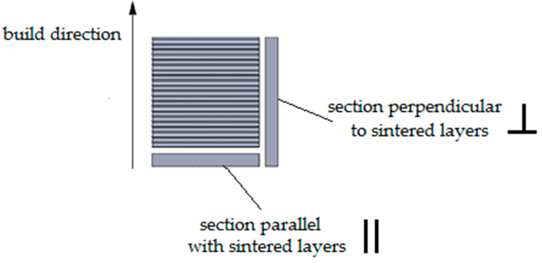
  • in the hardness between the samples prepared at different laser power—the comparison within each of the four groups (A—sintered, perpendicular direction, B—sintered-annealed, perpendicular direction, C—sintered, parallel direction, D—sintered-annealed, parallel direction)
  • in the hardness of the materials sintered and sintered-annealed in a particular direction—comparison between the two groups (A and B—sintered and sintered-annealed in the perpendicular direction, C and D—sintered and sintered-annealed in the parallel direction)
  • in the hardness of the materials in two different directions—the comparison between the two groups (A and C—sintered in the perpendicular and parallel direction, B and D—sintered-annealed in the perpendicular and parallel direction)
One-way analysis of variance (ANOVA) was used to compare materials sintered at different laser powers (nine levels of laser power, nine groups of materials). The one-way ANOVA is used to determine whether there are any significant differences between the means of three or more independent (unrelated) groups. The one-way ANOVA compares the means between the groups you are interested in and determines whether any of those means are significantly different from each other.
Distributional Fischer assumptions for ANOVA [39]
  • Independence of observations.
  • Normality of sampling distribution
  • Equal variance (homogeneity)
The independence assumption is based on the way data are collected. The hardness was monitored for ten different samples made at individual different laser power of 150 over 190 W. Groups of data for particular laser power are then independent.
We can to asses normality graphically before we carry out a Shapiro–Wilks test. We can select a histogram, the Q-Q plot, the P-P plot, and a box plot for assessing normality. The null-hypothesis of the Shapiro-Wilk test for normality is that the population is normally distributed. Thus, if the p-value is less than the chosen α level, then the null hypothesis is rejected and there is evidence that the data tested are not from a normally-distributed population, the data are not normal. On the contrary, if the p-value is greater than the chosen alpha level, then the null hypothesis that the data came from a normally distributed population cannot be rejected.
Homogeneity of variances means that the population variances in each group are equal. All selections are the same, using Cochran’s test or Hartley’s test for homogeneity of variances.
Test: H0: σ 1 2 = σ 2 2 = σ 3 2 = σ k 2 : H1: non-H0, where σ is variance of population.
Hartley’s Fmax test is probably the simplest test of homogeneity of variances. It is not very sensitive to departures from homogeneity. Cochran’s test is another relatively simple homogeneity of variance test. It uses the ratio of the largest variance to the sum of the variances as the test statistic. Since it uses more information it is more powerful than Hartley’s Fmax test, at least for small, equal sample sizes.
All tested groups of materials (A, B, C, and D) were tested using Shapiro–Wilks, Cochran’s, and Hartley’s tests. Results of these tests for all tested groups confirmed that Fisher assumptions for the use of ANOVA are met.
To determine the influence of annealing (comparison between sintered and sintered-annealed materials in a particular build direction) or the build direction at a particular laser power used the t-test and F-test. The t-test is probably the most commonly used statistical data analysis procedure for hypothesis testing. Actually, there are several kinds of t-tests, but the most common is the “two-sample t-test” also known as the “Student’s t-test”:
H0: μ1 = μ2 and then H1: μ1 ≠ μ2,
where H0 is the null hypothesis, H1 is the alternative hypothesis, and μ1, μ2 are the means of sets of data.
It can be used to determine if two sets of data are significantly different from each other. The two-sample t-test simply tests whether or not two independent populations have different mean values on some measure.
We consider three cases where the t distribution is used:
  • Equal variances
  • Unequal variances
  • Paired samples
The F-test is designed to test if two population variances are equal. It does this by comparing the ratio of two variances. To compare the variances of two quantitative variables, the hypotheses of interest are:
H 0 :   σ 1 2 = σ 2 2  and then  H 1 :   σ 1 2 σ 2 2 ,
where σ1 and σ2 are variances of the sets of data.
The test statistic in an F-test is the ratio of two scaled sums of squares reflecting different sources of variability. These sums of squares are constructed so that the statistic tends to be greater when the null hypothesis is not true. In order for the statistic to follow the F-distribution under the null hypothesis, the sums of squares should be statistically independent, and each should follow a scaled chi-squared distribution. One of the most important steps of a test to compare two population variances is to check the equal variances assumption if you want to use the pooled variances t-test. According to the results of the F-test we choose the t-test (equal variances, unequal variances).

3. Results and Discussion

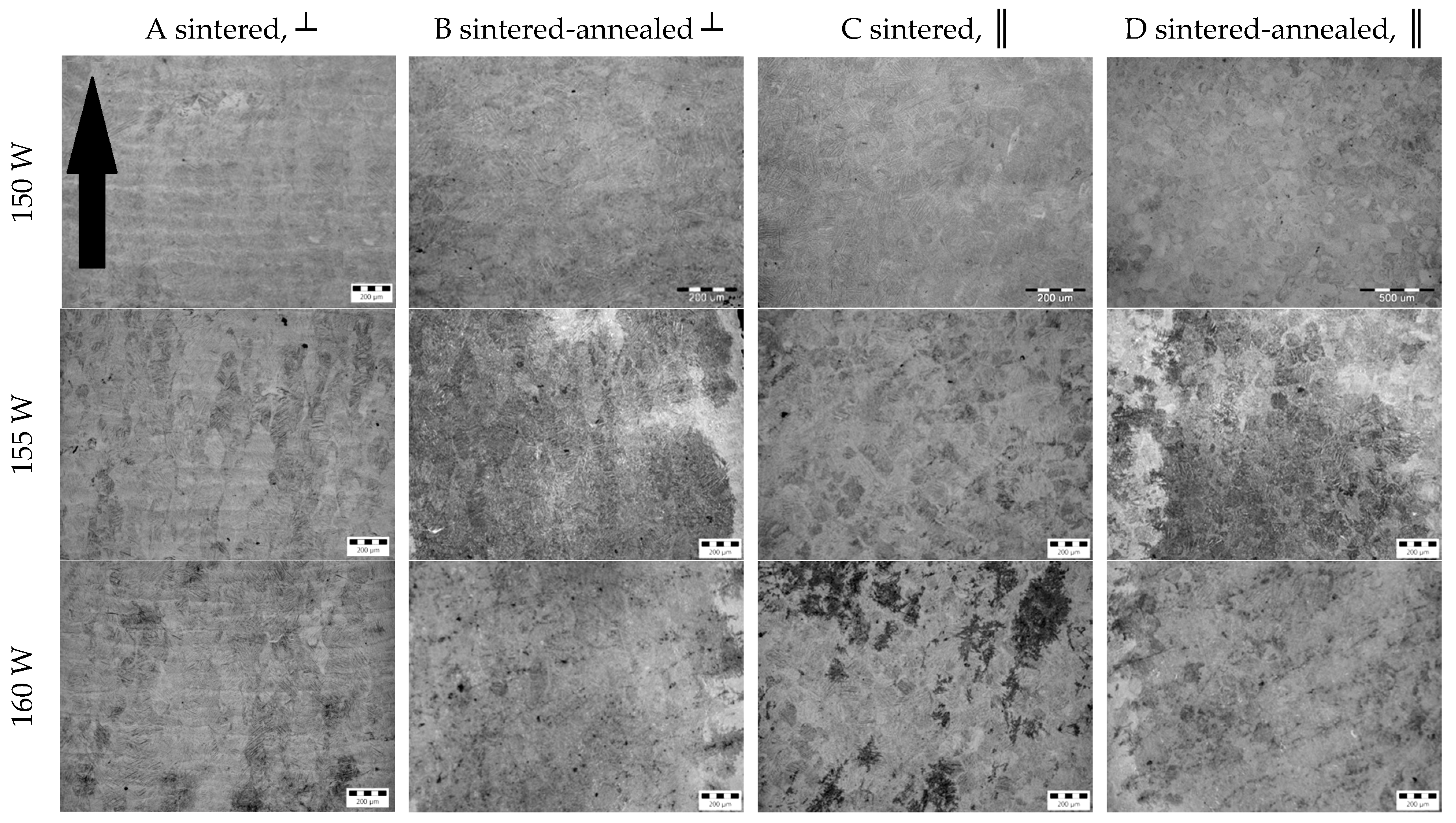
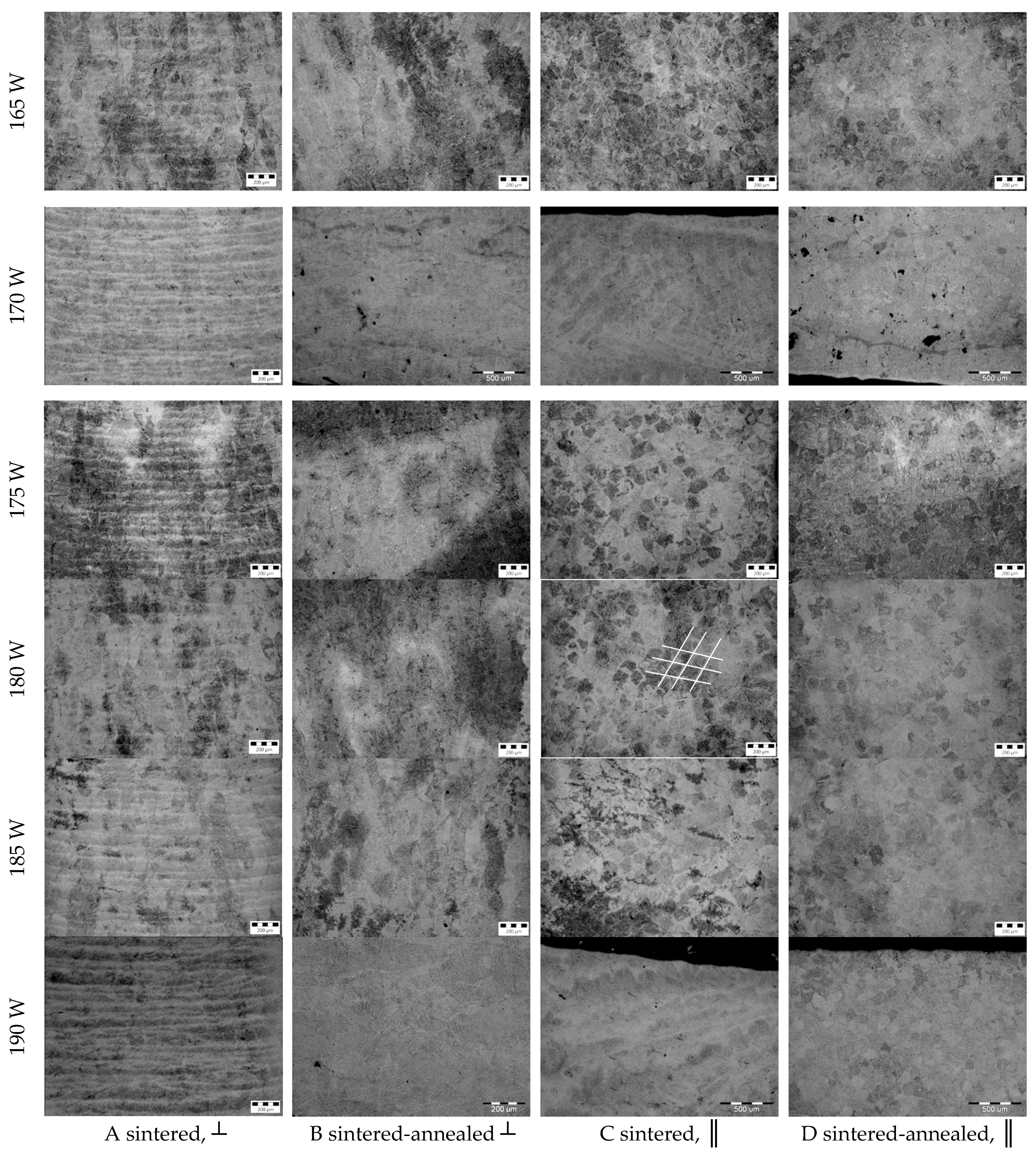
3.1. Microstructure of Materials

The microstructure of individual sintered and sintered-annealed materials produced at different laser powers is shown in Figure 6.
Similar to [32], the microstructure is characterized by large, elongated prior β-phase grain boundaries that are filled with very fine needles of acicular α′-martensite. In group A and B (cross-section perpendicular to sintered layers) we can see, that the prior β-phase boundaries grow epitaxially during the material processing and grow parallel to the build direction as a consequence of the thermal history experienced by the layers. The structures in columns C and D are characterized by equiaxed grains—perpendicular cuts of elongated prior β-phase grains
On all cross-sections of group A, the pattern of sintered layers is evident. In column C, the plane of the laser sintering can be recognized by the grid plan pattern (indicated by white lines in C-180 W). In columns B and D, corresponding to the annealed structure, the visible pattern disappears.
There is no visible difference between the microstructure of materials made under different laser powers (within columns). Based on [15,31,32] it can be stated that laser power affects the heat input during sintering, and then the microstructure; we suppose that final properties of material depends on the amount of particular phases. To confirm this assumption, complex phase analysis of the materials is required. However, this is beyond the scope of this article.

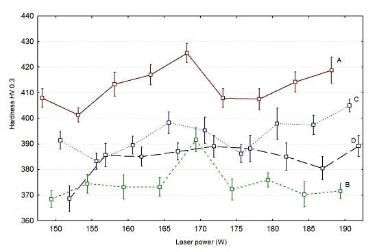
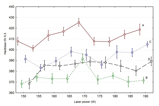
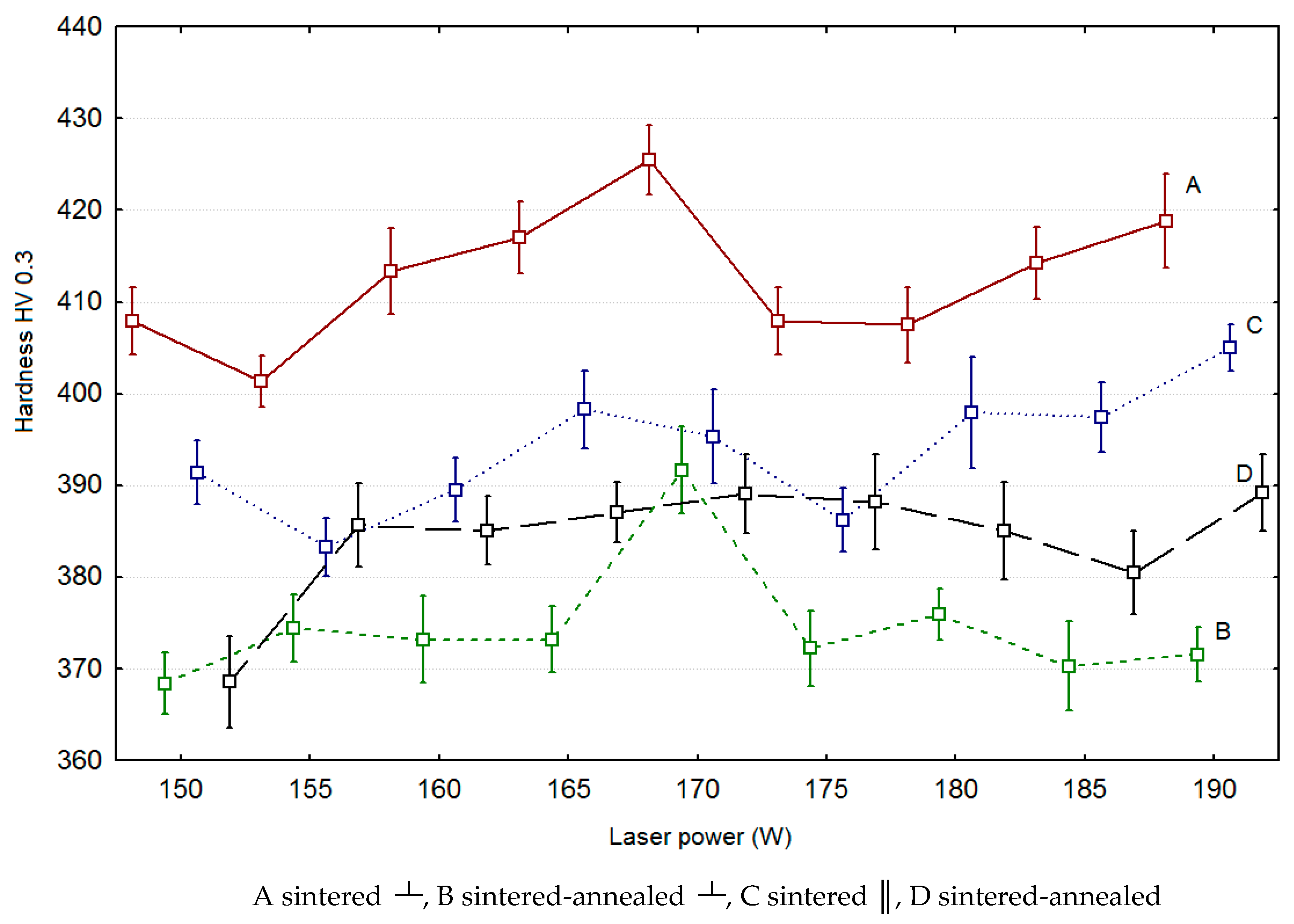
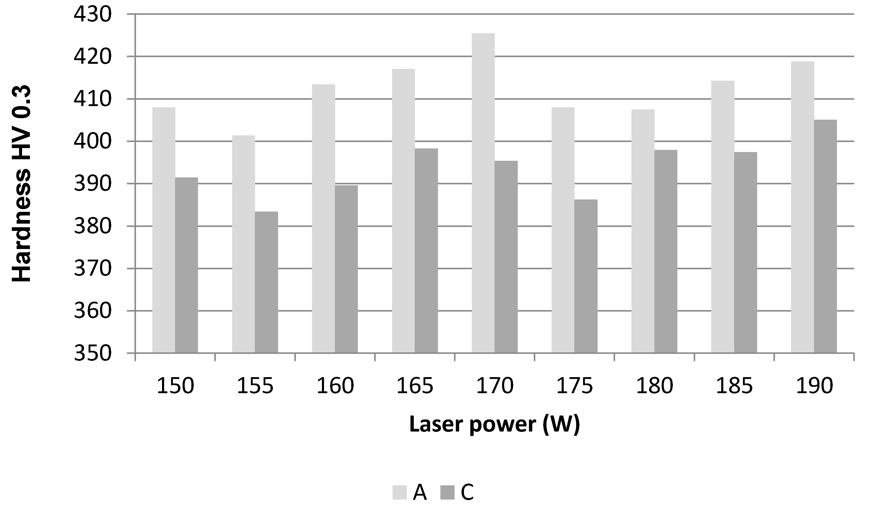
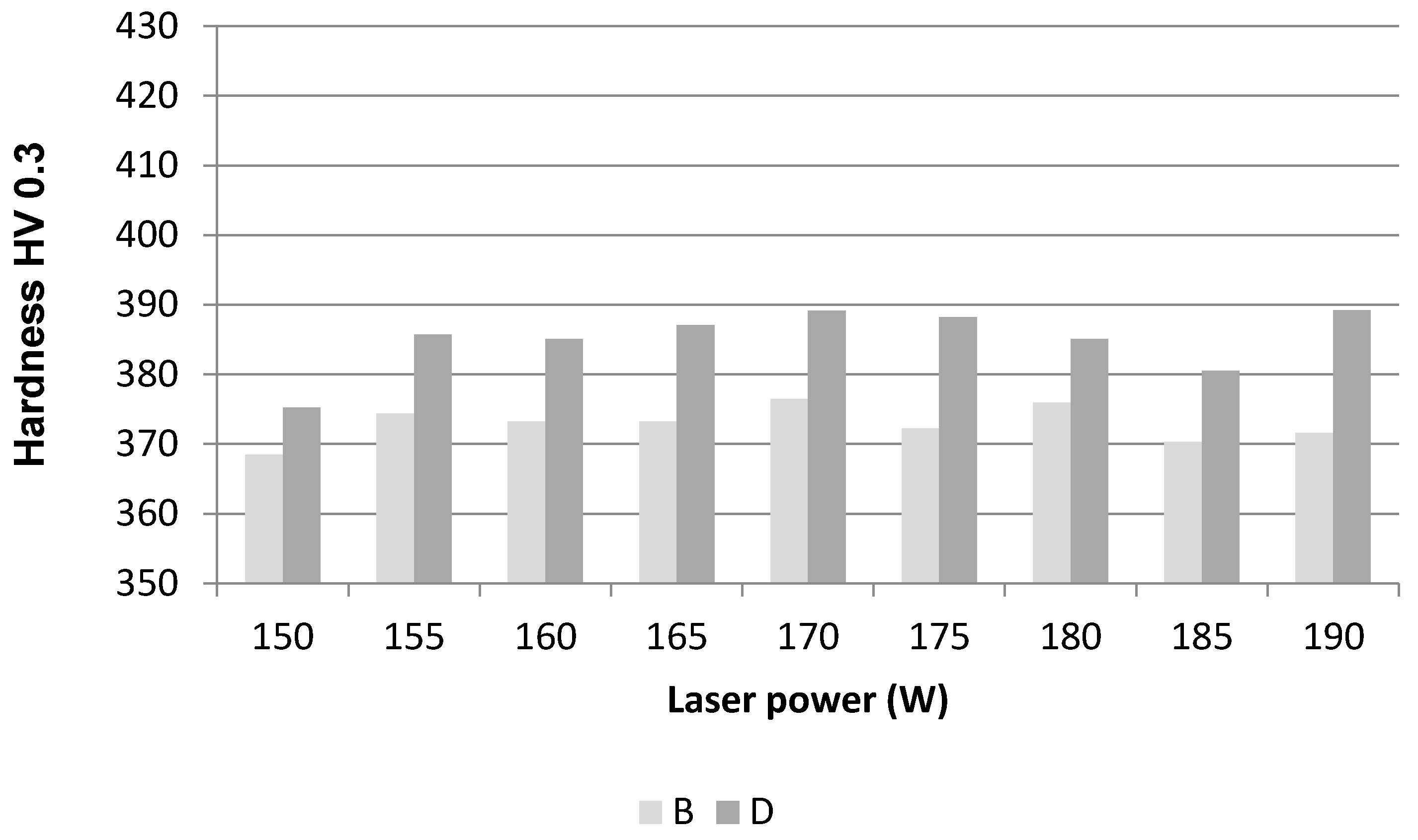
3.2. Effect of Laser Power on the Hardness

The effect of laser power on the hardness was tested by one-way ANOVA. When applying the ANOVA method, if the null hypothesis H0, that if all of the groups’ means are equal, is rejected at the level of significance then the alternative hypothesis H1 is favored, and it is necessary to identify which pairs of mean values differ statistically significantly at that level of significance. This next process is called “post hoc” analysis and consists of comparing the mean values of all pairs of selections. For this multiple comparison, different statistical methods are used, e.g., Fisher’s, Tukey’s, and Scheffe’s method. We use Tukey’s method because the sample sizes are equal (balanced model).
The values for the sintered and sintered-annealed samples are graphically represented by boxplots on the Figure 7. The results of the ANOVA, an example of post hoc analysis (for groups A and B), and the results of the t-tests for the corresponding groups of materials are shown in Table 4, Table 5, Table 6 and Table 7.
The results of ANOVA for all groups of materials are listed in Table 4. Examples of post hoc analysis for groups A and B are listed in Table 5 and Table 6. The statistically significant differences are marked in bold.
When p < α, there is a statistically significant difference between the samples made using different laser powers, showing that laser power affects hardness.
Bold-marked values in Table 5 indicate couples of laser powers between which the statistically significant difference have been noted. There are, relatively, many couples with such differences within group A.
Since in all cases p > α, the annealing led to removing statistically significant differences in hardness between the individual laser powers.
In group C (similarly like in group A) a statistically significant difference between many couples of laser power was noted, showing that laser power affects hardness. However, in group D in almost all cases p > α, the annealing led to the removal statistically significant differences in hardness between the individual laser powers.

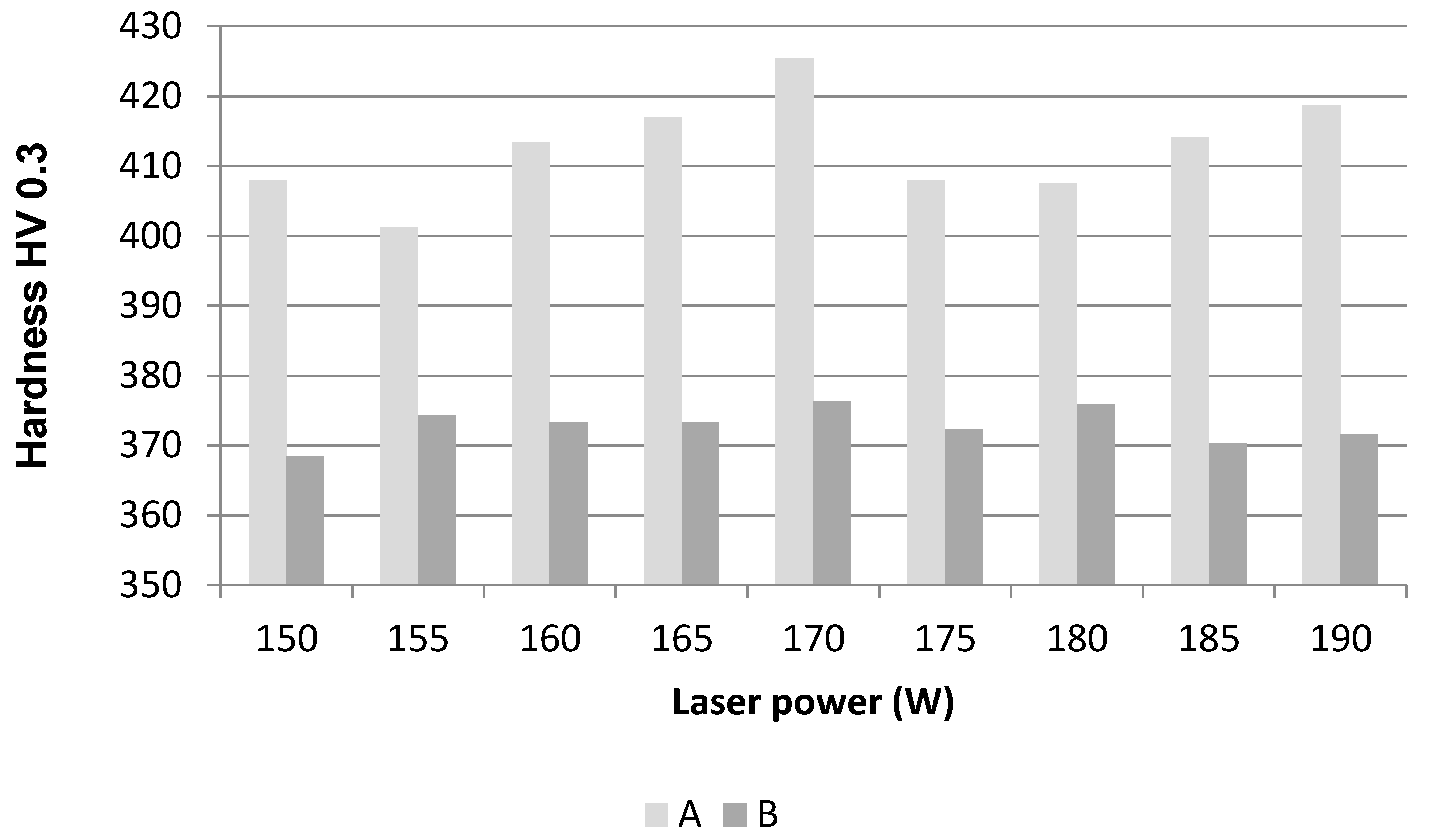
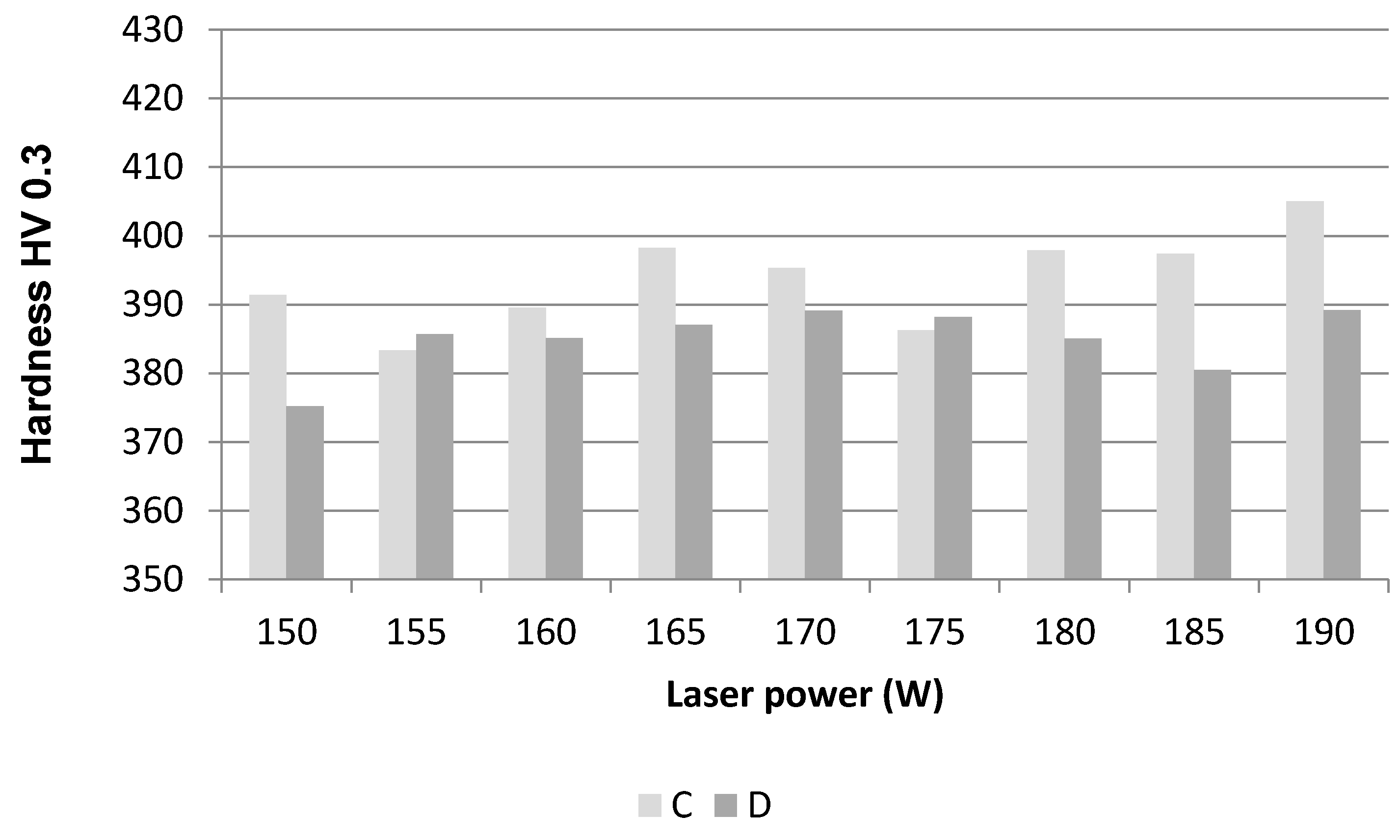
3.3 Comparison of the Hardness of Sintered and Sintered-Annealed Materials

Sintered samples have higher values than sintered-annealed samples, whether they have statistically significant differences between them was detected using the F-test and t-test. Figure 8 and Figure 9 show mean the value dependence of hardness on laser power.
From Figure 8 and Figure 9 it is apparent that annealing led to a decrease in hardness compared to the state after sintering in both directions. This is related to the disappearance of the layer pattern, which is evident from Figure 6. Based on the literature [32], it can be assumed that during sintering the intermetallic phase Ti3Al precipitates upon rapid cooling of the material due to the very low solubility of Al in Ti. The decrease in hardness of the materials after annealing can mean a reduction or partial dissolution of this phase.
The result of t-test is the p-value, Table 7. A p-value less than 0.05 (marked in bold) means the null hypothesis is rejected. This means that there is a statistical significant difference between sintered and sintered-annealed samples at different laser power.
It is evident from Table 7 (left two columns) that annealing leads to a statistically significant difference (decrease) in material hardness in the ⊥ direction (first column A-B). In the ║ direction (second column C-D), the differences in material hardness before and after annealing are less pronounced in the four laser powers, and are even statistically insignificant.

3.4. Comparison of the Hardness of Materials in Two Different Directions

Figure 10 and Figure 11 show the mean value dependence of hardness on laser power for particular materials.
Figure 10 and Figure 11 compare the hardness of the sintered and sintered-annealed materials in two mutually perpendicular directions. The hardness of the sintered materials is higher in the direction perpendicular to layers (Figure 10). Annealing led to a more pronounced decrease in hardness in the perpendicular direction, which is shown in sintered-annealed materials with higher hardness in the parallel direction (Figure 11).
The p-values of t-test are listed in Table 7 (right two columns). The result of the t-test is the p-value; if the p value is less than 0.05, then the null hypothesis is rejected. This means that there is a statistically significant difference between the two build directions for all laser powers, even in sintered and sintered-annealed materials.

4. Conclusions

Based on the analysis of experimentally-prepared samples, the following conclusions can be drawn:
-
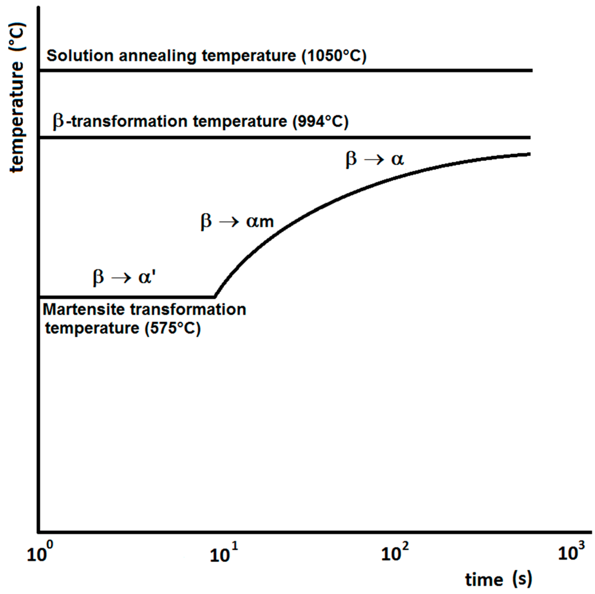
The microstructure is characterized by large, elongated prior β-phase grain boundaries that are filled with very fine needles of acicular α′-martensite.
-
The pattern of sintered layers is evident on metallographic cross-sections in the direction perpendicular to the sintered layers (layer thickness) and in the parallel direction (grid plan pattern) as well. After annealing, these patterns disappear.
-
Annealing has led to a reduction in hardness regardless of the direction of material assessment
-
ANOVA showed a statistically significant effect of the laser power on the hardness of both sintered and sintered-annealed materials, both in the perpendicular and parallel directions.
-
Post hoc analysis defined specific laser power couples, between which a statistically significant difference in material hardness was expressed; after stress-relief annealing statistically significant differences decrease in both the perpendicular and parallel directions.
-
Larger differences in material hardness due to annealing occur in the perpendicular direction compared to the parallel.
-
Statistically significant differences were found in the hardness of the materials in the perpendicular and parallel build directions.
-
Stress-relief annealing reduces differences in Ti6Al4V hardness between the two directions, contributing to the even distribution of hardness and, finally, isotropy of the mechanical properties of the final product sintered using DMLS technology.

Acknowledgments

This work was supported by the Ministry of Education, Science, Research and Sport of the Slovak Republic (KEGA grant 064TUKE-4/2016, VEGA 1/0424/17) and the Slovak Research and Development Agency projects (ITMS 26220220038) “Creation and technological support in the diagnostics of parts and nodes by computed tomography” and (APVV-14-0294) “Production and testing of custom-made hard tissues substitutions from hydroxyapatite (HA)”.

Author Contributions

Anna Guzanová conducted measurements of the hardness, and wrote the paper; Gabriela Ižaríková performed the statistical analysis of the data; Janette Brezinová conducted the analysis and interpretation of the results; Jozef Živčák conceived and designed the experiments; Dagmar Draganovská performed the statistical analysis of the data; and Radovan Hudák manufactured the test samples.

Conflicts of Interest

The authors declare no conflict of interest.

References

  1. De Damborenea, J.J.; Larosa, M.A.; Arenas, M.A.; Hernández-López, J.M.; Jardini, A.L.; Ierardi, M.C.F.; Zavaglia, C.A.C.; Filho, R.M.; Conde, A. Functionalization of Ti6Al4V scaffolds produced by direct metal laser for biomedical applications. Mater. Des. 2015, 83, 6–13. [Google Scholar] [CrossRef]
  2. Palmquist, A.; Shah, F.A.; Emanuelsson, L.; Omar, O.; Suska, F. A technique for evaluating bone ingrowth into 3D printed, porous Ti6Al4V implants accurately using X-ray micro-computedtomography and histomorphometry. Micron 2017, 94, 1–8. [Google Scholar] [CrossRef] [PubMed]
  3. Li, Q.; Kucukkoc, I.; Zhang, D.Z. Production planning in additive manufacturing and 3D printing. Comput. Oper. Res. 2017, 83, 157–172. [Google Scholar] [CrossRef]
  4. Bertol, L.S.; Júnior, W.K.; da Silva, F.P.; Aumund-Kopp, C. Medical design: Direct metal laser sintering of Ti-6Al-4V. Mater. Des. 2010, 31, 3982–3988. [Google Scholar] [CrossRef]
  5. Song, B.; Dong, S.; Liao, H.; Coddet, C. Process parameter selection for selective laser melting of Ti6Al4V based on temperature distribution simulation and experimental sintering. Int. J. Adv. Manuf. Technol. 2012, 61, 967–974. [Google Scholar] [CrossRef]
  6. Yadroitsev, I.; Krakhmalev, P.; Yadroitsava, I. Selective laser melting of Ti6Al4V alloy for biomedical applications: Temperature monitoring and microstructural evolution. J. Alloys Compd. 2014, 583, 404–409. [Google Scholar] [CrossRef]
  7. Sedlák, J.; Ptáčková, M.; Nejedlý, J.; Madaj, M.; Dvořáček, J.; Zouhar, J.; Charvát, O.; Píška, M.; Rozkošný, L. Material analysis of titanium alloy produced by direct metal laser sintering. Int. J. Metalcast. 2013, 7, 43–50. [Google Scholar] [CrossRef]
  8. Petroušek, P.; Bidulská, J.; Bidulský, R.; Kočiško, R.; Fedoriková, A.; Hudák, R.; Rajťúková, V.; Živčák, J. Mechanical properties and porosity of Ti-6Al-4V alloy prepared by AM technology. MM Sci. J. 2017, 2, 1752–1755. [Google Scholar] [CrossRef]
  9. Živčák, J.; Šarik, M.; Hudák, R. FEA simulation of thermal processes during the direct metal laser sintering of Ti64 titanium powder. Measurement 2016, 94, 893–901. [Google Scholar] [CrossRef]
  10. Schnitzer, M.; Lisý, M.; Hudák, R.; Živčák, J. Experimental measuring of the roughness of test samples made using DMLS technology from the Titanium alloy Ti-6Al-4V. In Proceedings of the SAMI, Herľany, Slovakia, 22–24 January 2015; IEEE: Košice, Slovakia, 2015. [Google Scholar]
  11. Wikipedia. Selective Laser Sintering. Available online: http://en.wikipedia.org/wiki/Selective_laser_sintering (accessed on 30 April 2017).
  12. Patterson, A.E.; Messimer, S.L.; Farrington, P.A. Overhanging Features and the SLM/DMLS Residual Stresses Problem: Review and Future Research Need (Special Issue in Additive Manufacturing Technologies and Applications). Technologies 2017, 5, 1–21. [Google Scholar] [CrossRef]
  13. Brezinová, J.; Hudák, R.; Guzanová, A.; Draganovská, D.; Ižaríková, G.; Koncz, J. Direct Metal Laser Sintering of Ti6Al4V for Biomedical Applications: Microstructure, Corrosion Properties and Mechanical Treatment of Implants. Metals 2016, 6, 171. [Google Scholar] [CrossRef]
  14. Khairallah, S.A.; Anderson, A.T. Mesoscopic simulation model of selective laser melting of stainless steel powder. J. Mater. Process. Technol. 2014, 214, 2627–2636. [Google Scholar] [CrossRef]
  15. Kruth, J.-P.; Mercelis, P.; van Vaerenbergh, J.; Froyen, L.; Rombouts, M. Binding mechanisms in selective laser sintering and selective laser melting. Rapid Prototyp. J. 2005, 11, 26–36. [Google Scholar] [CrossRef]
  16. Weißmann, V.; Bader, R.; Hansmann, H.; Laufer, N. Influence of the structural orientation on the mechanical properties of selective laser melted Ti6Al4V open-porous scaffolds. Mater. Des. 2016, 95, 188–197. [Google Scholar] [CrossRef]
  17. Konečná, R.; Kunz, L.; Bača, A.; Nicoletto, G. Long fatigue crack growth in Ti6Al4V produced by direct metal laser sintering. Procedia Eng. 2016, 160, 69–76. [Google Scholar] [CrossRef]
  18. Milton, S.; Morandeau, A.; Chalon, F.; Leroy, R. Influence of finish machining on the surface integrity of Ti6Al4V produced by Selective Laser Melting. Procedia CIRP 2016, 45, 127–130. [Google Scholar] [CrossRef]
  19. Bača, A.; Konečná, R.; Nicoletto, G.; Kunz, L. Influence of build direction on the fatigue behaviour of Ti6Al4V alloy produced by direct metal laser sintering. Mater. Today Proc. 2016, 3, 921–924. [Google Scholar] [CrossRef]
  20. Wauthle, R.; Vrancken, B.; Beynaerts, B.; Jorissen, K.; Schrooten, J.; Kruth, J.-P.; Humbeeck, J.V. Effects of build orientation and heat treatment on the microstructure and mechanical properties of selective laser melted Ti6Al4V lattice structures. Addit. Manuf. 2015, 5, 77–84. [Google Scholar] [CrossRef]
  21. Sidambe, A.T. Three dimensional surface topography characterization of the electron beam melted Ti6Al4V. Met. Powder Rep. 2017, 72, 200–205. [Google Scholar] [CrossRef]
  22. Vastola, G.; Zhang, G.; Pei, Q.X.; Zhang, Y.-W. Controlling of residual stress in additive manufacturing of Ti6Al4V by finite element modeling. Addit. Manuf. 2016, 12, 231–239. [Google Scholar] [CrossRef]
  23. Abe, F.; Santos, E.C.; Kitamura, Y.; Osakada, K.; Shiomi, M. Influence of forming conditions on the titanium model in rapid prototyping with the selective laser melting process. J. Mech. Eng. Sci. 2003, 217, 119–126. [Google Scholar] [CrossRef]
  24. De Damboreneaa, J.J.; Arenasa, M.A.; Larosa, M.A.; Jardini, A.L.; de Carvalho Zavaglia, C.A.; Condea, A. Corrosion of Ti6Al4V pins produced by direct metal laser sintering. Appl. Surf. Sci. 2017, 393, 340–347. [Google Scholar] [CrossRef]
  25. Zatkalíková, V.; Palček, P.; Markovičová, L.; Chalupová, M. Analysis of fractured screw shaped Ti6Al4V dental implant. Mater. Today Proc. 2016, 3, 1216–1219. [Google Scholar] [CrossRef]
  26. Pyka, G.; Kerckhofs, G.; Papantoniou, I.; Speirs, M.; Schrooten, J.; Wevers, M. Surface Roughness and Morphology Customization of Additive Manufactured Open Porous Ti6Al4V. Struct. Mater. 2013, 6, 4737–4757. [Google Scholar] [CrossRef] [PubMed]
  27. Lawley, A.; Murphy, F.T. Metallography of powder metallurgy materials. Mater. Charact. 2003, 51, 315–327. [Google Scholar] [CrossRef]
  28. Hong, K.-M.; Shin, Y.C. Analysis of microstructure and mechanical properties change in laserwelding of Ti6Al4V with a multiphysics prediction model. J. Mater. Process. Technol. 2016, 237, 420–429. [Google Scholar] [CrossRef]
  29. Li, X.; Van Humbeeck, J.; Kruth, J.-P. Selective laser melting of weak-textured commercially pure titanium with high strength and ductility: A study from laser power perspective. Mater. Des. 2017, 116, 352–358. [Google Scholar] [CrossRef]
  30. Mercelis, P.; Kruth, J.-P. Residual stresses in selective laser sintering and selective laser melting. Rapid Prototyp. J. 2006, 12, 254–265. [Google Scholar] [CrossRef]
  31. Kruth, J.-P.; Deckers, J.; Yasa, E.; Wauthlé, R. Assessing and comparing influencing factors of residual stresses in selective laser melting using a novel analysis method. Proc. Inst. Mech. Eng. 2012, 226, 980–991. [Google Scholar] [CrossRef]
  32. Thijs, L.; Verhaeghe, F.; Craeghs, T.; van Humbeeckm, J.; Kruth, J.-P. A study of the microstructural evolution during selective laser melting of Ti–6Al–4V. Acta Mater. 2010, 58, 3303–3312. [Google Scholar] [CrossRef]
  33. Raju, R.; Duraiselvam, M.; Petley, V.; Verma, S.; Rajendran, R. Microstructural and mechanical characterization of Ti6Al4V refurbished parts obtained by laser metal deposition. Mater. Sci. Eng. A 2015, 643, 64–71. [Google Scholar] [CrossRef]
  34. Konečná, R.; Kunz, L.; Bača, A.; Nicoletto, G. Resistance of direct metal laser sintered Ti6Al4V alloy against growth of fatigue cracks. Eng. Fract. Mech. 2017. [Google Scholar] [CrossRef]
  35. EOS e-Manufacturing Solutions. Available online: https://cdn2.scrvt.com/eos/fe8d0271508e1e03/d6e4d305e880/EOS_Titanium_Ti64_en.pdf (accessed on 5 July 2017).
  36. Standard by ASTM International. ASTM F136-13, Standard Specification for Wrought Titanium-6Aluminum-4Vanadium ELI (Extra Low Interstitial) Alloy for Surgical Implant Applications (UNS R56401); ASTM International: West Conshohocken, PA, USA, 2013; Available online: https://www.astm.org (accessed on 30 May 2017).
  37. Longhitano, G.; Larosa, M.; Munhoz, A.; Zavaglia, C.; Ierardi, M. Surface Finishes for Ti-6Al-4V Alloy Produced by Direct Metal Laser Sintering. Mater. Res. 2015, 18, 838–842. [Google Scholar] [CrossRef]
  38. Laser Sintering System EOSINT M 280. Available online: https://webbuilder5.asiannet.com/ftp/2684/TD_M280_en_2011-03-29.pdf (accessed on 20 July 2017).
  39. Montgomery, D.C. Design and Analysis of Experiments, 8th ed.; John Wiley & Sons, Inc.: Hoboken, NJ, USA, 2013; Available online: http://eu.wiley.com/WileyCDA/WileyTitle/productCd-1118097939.html (accessed on 14 August 2017).
Figure 1. Principle of direct metal laser sintering (DMLS) technology [11].
Metals 07 00318 g001
Figure 2. Time-temperature transformation diagram for Ti6Al4V alloy.
Metals 07 00318 g002
Figure 3. Ti6Al4V powder for DMLS technology. Reproduced with permission from author of [37].
Metals 07 00318 g003
Figure 4. Method of material collection for metallographic observation.
Metals 07 00318 g004
Figure 5. Pattern of hardness measurement.
Metals 07 00318 g005
Figure 6. Microstructure of analyzed materials, magnification: 100×; the black arrow in the first figure indicates the build orientation and applies to all figures in column A.
Metals 07 00318 g006aMetals 07 00318 g006b
Figure 7. Boxplots for the sintered and sintered-annealed samples.
Metals 07 00318 g007
Figure 8. Hardness versus laser power for (A) sintered ┴, and (B) sintered-annealed, ┴.
Metals 07 00318 g008
Figure 9. Hardness versus laser power for (C) sintered, ║ and (D) sintered-annealed, ║.
Metals 07 00318 g009
Figure 10. Hardness versus laser power for (A) sintered ┴ and (C) sintered║.
Metals 07 00318 g010
Figure 11. Hardness versus laser power for (B) sintered-annealed ┴ and (D) sintered-annealed ║.
Metals 07 00318 g011
Table 1. Chemical composition of the Ti6Al4V alloy [35].
Element AlVONHFeSiCTi
Wt. %6.054.040.1200.0010.0010.050.050.03Bal.
ASTM F1365.50–6.503.50–4.50-
Table 2. Material characteristics of the Ti6Al4V alloy (as built, in the XY horizontal direction) * [35].
Microhardness400–430 HV
Ultimate tensile strength1290 ± 50 MPa
Young’s modulus110 ± 15 GPa
Yield strength1140 ± 50 MPa
Density 4.41 kg/dm3
Thermal conductivity6.6 W/m °C
Max. long-term operating temperature350 °C
Melting point1670 °C
Relative elongation7 ± 3%
Min. thickness of layer30 μm
Min. Thickness of Wall0.3–0.4 mm
* The data are valid for the powder material Electro Optical Systems (EOS) Titanium Ti64 powder, processed using EOSINT M 280/400 W with PSW 3.6 and parameter set Ti64_Speed 1.0.
Table 3. Taguchi design of experiments.
Laser Power (W)150155160165170175180185190Group
SinteredA
C
Sintered-annealedB
D
┴—metallographic section perpendicular to sintered layers; ‖—metallographic section parallel with sintered layers.
Table 4. Results of ANOVA for analysed groups of materials.
VariableOne-Way ANOVA, Marked Effects are Significant at p < 0.0500
SS Effectdf EffectMS EffectSS Errordf ErrorMS ErrorFP
A12,676.0381584.50430,090.93261115.290913.74532<0.00005
B11,040.6381380.01929,191.8261111.84612.3391<0.00005
C11,086.0781385.75830,735.43261117.760311.76762<0.00005
D4952.9418619.117635,401.00261135.63604.6545520.000032
SS: sum of squares; df: degrees of freedom; MS: mean sum of squares; F: F-statistic; P: p-value. All bold letters means data < p-value.
Table 5. Post hoc analysis for group A, sintered, ┴.
ATukey HSD Test, Error: MS = 115.29, df = 261
150155160165170175180185190
150-0.28780.57170.0309<0.000051.00001.00000.36650.0030
1550.2878-0.0005<0.00005<0.000050.28780.38960.0001<0.00005
1600.57170.0005-0.93210.00050.57170.45380.99990.5802
1650.0309<0.000050.9321-0.05760.03090.01770.98620.9993
170<0.00005<0.000050.00050.0576-<0.00005<0.000050.00170.0281
1751.00000.28780.57170.0309<0.00005-1.00000.36650.0030
1801.00000.38960.45380.0177<0.000051.0000-0.26810.0015
1850.36650.00010.99990.98620.00170.36650.2681-0.7785
1900.0030<0.000050.58020.99930.02810.00300.00150.7785-
All bold letters means data < p-value.
Table 6. Post hoc analysis for group B, sintered-annealed, ┴.
BTukey HSD Test, Error: MS = 115.29, df = 261
150155160165170175180185190
150-0.41540.71010.7101<0.000050.90140.12780.99990.9647
1550.4154-0.99990.9999<0.000050.99710.99970.85530.9835
1600.71010.9999-1.0000<0.000050.99990.98590.97790.9996
1650.71010.99991.0000-<0.000050.99990.98590.97790.9996
170<0.00005<0.00005<0.00005<0.00005-<0.00005<0.00005<0.00005<0.00005
1750.90140.99710.99990.9999<0.00005-0.91020.99871.0000
1800.12780.99970.98590.9859<0.000050.9102-0.49040.8057
1850.99990.85530.97790.9779<0.000050.99870.4904-0.9999
1900.96470.98350.99960.9996<0.000051.00000.80570.9999-
All bold letters means data < p-value.
Table 7. Results of t-test: the comparison between sintered and sintered-annealed samples (left) and between perpendicular and parallel direction (right).
Laser Power (W)SinteredSintered-Annealed
A-BC-DA (┴)-C (║)B (┴)-D (║)
1503.80 × 10−237.94 × 10−98.57 × 10−90.0059
1556.24 × 10−170.39004.14 × 10−120.0002
1605.40 × 10−170.08002.54 × 10−110.0002
1655.83 × 10−247.04 × 10−51.10 × 10−83.13 × 10⁻⁷
1707.31 × 10−270.06002.11 × 10−132.22 × 10⁻⁵
1753.83 × 10−190.52002.33 × 10−128.26 × 10⁻⁶
1802.68 × 10−170.00190.01030.0032
1851.95 × 10−192.26 × 10−73.71 × 10−80.0028
1907.01 × 10−213.17 × 10−87.84 × 10−65.10 × 10⁻⁹
All bold letters means data < p-value.

