Reduction of Induced Central Damage in Cold Extrusion of Dual-Phase Steel DP800 Using Double-Pass Dies


Department of Manufacturing Engineering, Universidad Nacional de Educación a Distancia (UNED), 28040 Madrid, Spain
*
Author to whom correspondence should be addressed.
Metals 2017, 7(9), 335; https://doi.org/10.3390/met7090335
Submission received: 25 July 2017
/
Revised: 29 August 2017
/
Accepted: 30 August 2017
/
Published: 31 August 2017
(This article belongs to the Special Issue Advances in Plastic Forming of Metals)
Abstract
:Advanced High Strength Steels (AHSS) are a promising family of materials for applications where a high strength-to-weight ratio is required. Central burst is a typical defect commonly found in parts formed by extrusion and it can be a serious problem for the in-service performance of the extrudate. The finite element method is a very useful tool to predict this type of internal defect. In this work, the software DEFORM-F2 has been used to choose the best configurations of multiple-pass dies, proposed as an alternative to single-pass extrusions in order to minimize the central damage that can lead to central burst in extruded parts of AHSS, particularly, the dual-phase steel DP800. It has been demonstrated that some geometrical configurations in double-pass dies lead to a minimum value of the central damage, much lower than the one obtained in single-pass extrusion. As a general rule, the position of the minimum damage leads to choosing higher values of the contacting length between partial reductions (L) for high die semiangles (α) and to lower values of the reduction in the first pass (RA) for low total reductions (RT). This methodology could be extended to find the best configurations for other outstanding materials.
1. Introduction
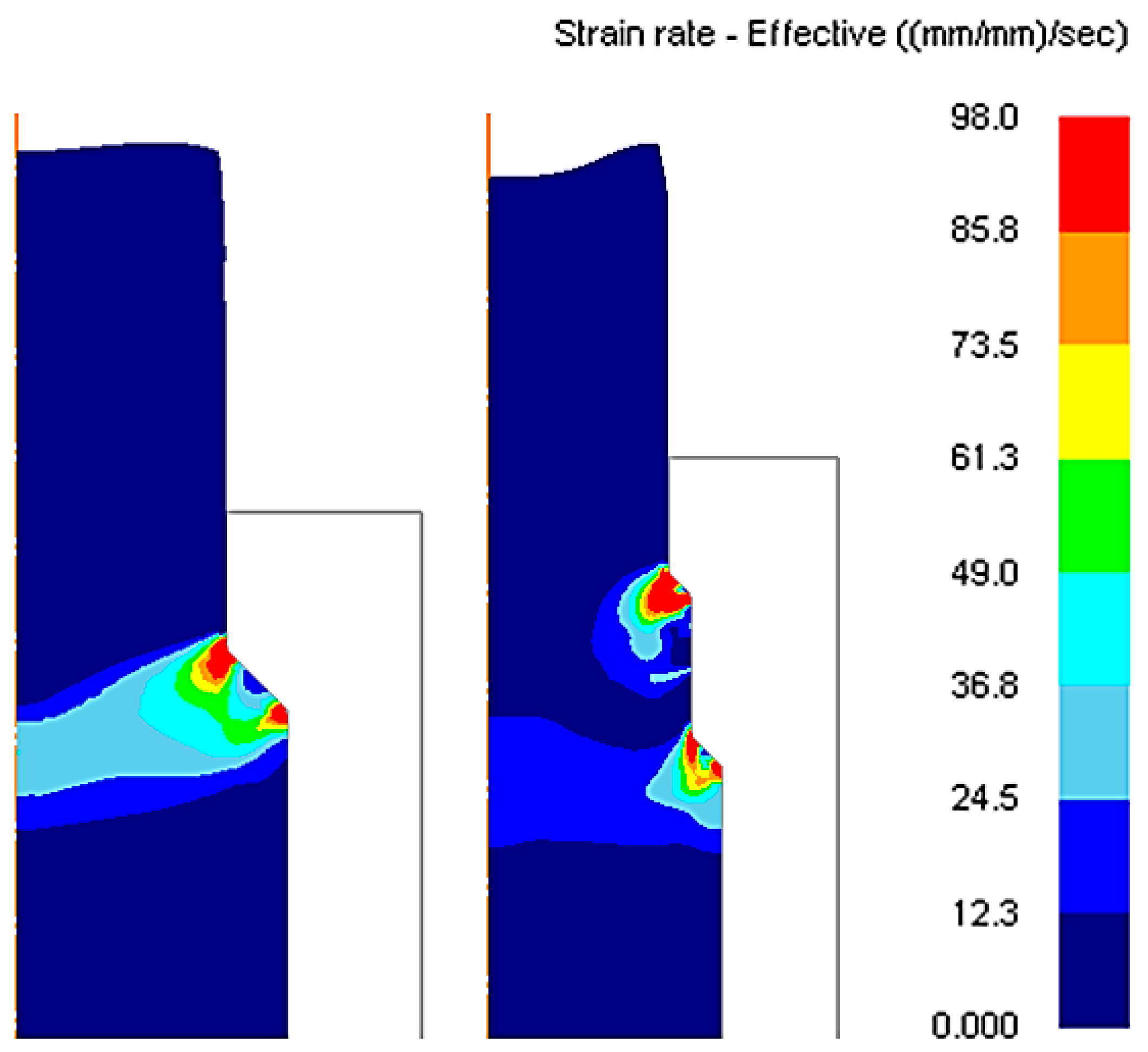
Advanced High Strength Steels (AHSS) are an emerging family of materials for applications where a high strength-to-weight ratio is required, such as aeronautical and automotive ones [1]. The interest of these steels is not only focused on the in-service behavior of the components, but also in the response of machines and tools to support the high forces required to produce the final shapes; this problem has been faced, for example, in previous studies where the finite element simulation of the system press-tool behavior in the stamping processes was used to define criteria for the best design of high-cost dies and punches [2]. The die is a critical part of the system press-tool in forming processes, as it is in direct contact with the workpiece to be formed. Die design has to be optimal in order to increase the tool life and to produce products of the required quality; however, studies about other related topics such as the optimization of multi-axis high-speed milling are also becoming very important when dies of complex shape have to be manufactured [3], as well as the improvement in finishing operations of forming tools, as in the work of López de Lacalle et al. [4], especially focused in the machining of AHSS. Dual-Phase steels (DP) are one interesting group of AHSS, whose microstructure is mainly composed of soft ferrite, with islands of hard martensite dispersed throughout [5]. Thus, the strength level of these steels is related to the amount of martensite in the microstructure. A wide variety of DP grades exhibiting different strength and ductility levels are currently industrially produced; however, it is still a challenge to improve their formability during their processing. As stated by Moeini et al. [6], a lot of scientific work is being done to improve the knowledge about the effect of microstructure on the mechanical properties of DP steels [7,8,9]. Due to their different mechanical properties compared to conventional steels, it becomes necessary to know the behavior of these advanced materials under different processing techniques to determine the best operating conditions that ensure a good quality of the final product [10,11]. Some structural components of car bodies in the automotive industry are obtained by extrusion processes, which are commonly classified in direct/forward and indirect/backward ones. In direct extrusion, the directions of work piece and tool movement are identical, and the most relevant parameters are the die semiangle, the extrusion ratio, the friction, and material properties [12]. On the other hand, the most typical defect encountered in extruded parts is “chevron cracking”, also called “central burst”. Parghazeh and Haghighat [13] have recently developed an upper bound model to predict the appearance of central bursting defects in rod extrusion processes. This defect, that can also be associated with drawing operations [14], can seriously affect the quality of the extrudate and its in-service performance; and it can be especially problematic because central burst is an internal defect and it cannot be detected by visual inspection techniques. As explained in [15], this was a serious problem in the mid-1960s for automotive companies which encountered important problems of axle shaft breakage leading to 100% inspection. Although fractures are important, there is a growing interest of the scientific community to study the appearance and evolution of damage in general, particularly in dual-phase steels [16,17,18], as it can lead to failure. Damage can affect the mechanical properties of a component under service loads [19]. Reduction of damage that can lead to central burst appearance in DP800 steel obtained by cold forward extrusion is investigated in this paper. Central bursts are internal fractures caused by high hydrostatic tension in combination with internal material weaknesses, mainly porosity [20]. The hydrostatic stress criterion (HSC) has been typically used to predict central burst occurrence [14,21]. This criterion states that “whenever hydrostatic stress at a point on the center line in the deformation zone becomes zero and it is compressive elsewhere, there is fracture initiation leading to central burst” [22]. However, if the level of hydrostatic tension can be kept below a critical level, bursting can likely be avoided. This may be accomplished by a change in lubricant, die profile, temperature, deformation level, or process rate [20]. In multi-pass extrusions, each forming pass plays an important role in decreasing the hydrostatic stress due to the counter pressure effect; previous studies [23,24] have demonstrated that the application of counter pressure decreases the central damage accumulation, which leads to an increase of the material formability, even for brittle materials. When fracture is already presented in the material with the appearance of cracks, the increase of the counter pressure results in a reduction of the crack size and, at a certain level of counter pressure, central burst can even disappear. In Figure 1, a comparison between a single and a double reduction with a double-pass die can be observed. In this last case (double-pass extrusion), the strain rate diagram along the longitudinal axis is divided in to two regions of a lower magnitude than in the case of single pass, resulting in different values of central damage. Partial reductions will determine the increase or reduction of the central damage in the final part compared to a single reduction. In this paper, we investigated which geometrical configurations lead to a decrease in central damage for the material DP800 considering double-pass extrusions; the methodology followed is presented in detail in order to be used for the analysis of other emerging materials.
2. Materials and Methods
2.1. Finite Element Modelling with DEFORM F2™
Unlike general purpose FEM codes, DEFORM is tailored for deformation modeling. This study has been realized using the finite element software DEFORM F2™ (Scientific Forming Technologies Corporation, Columbus, OH, USA); this code is especially designed to simulate axisymmetric metal forming operations such as the ones approached in this study [25].
DEFORM F2™ (Scientific Forming Technologies Corporation, Columbus, OH, USA) preprocessor uses a graphical user interface to integrate the data required to run the simulation. Input data includes:
- Object description: all data associated with an object, including geometry, mesh, temperature, material, etc.
- Material data: data describing the behavior of the material under the conditions which will experience during deformation.
- Inter object conditions: describes how the objects interact with each other, including contact and friction conditions between objects.
- Simulation controls: definition of parameters such as discrete time steps to model the process.
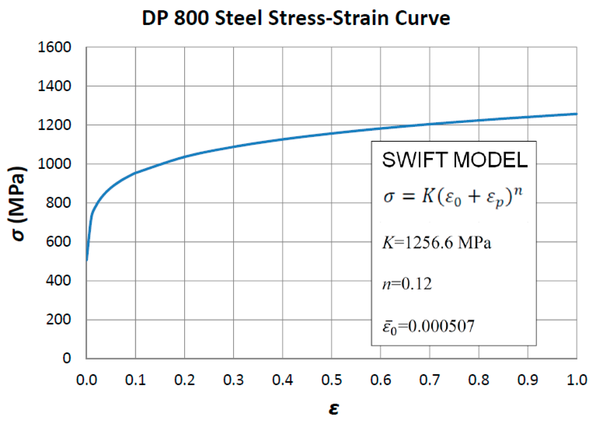
Extrusion dies are modelled as rigid parts and the workpiece is modelled as a deformable body. Regarding the material, the workpiece has been modelled with the dual-phase steel DP800, whose flow curve according to the Swift model is presented in Figure 2. The yield criterion adopted is von Mises, as it is the default setting for an isotropic material model and anisotropy influence has not been considered in this study.
The same geometry of the workpiece has been considered in all the simulations: one billet of initial diameter d0 = 20 mm and length L0 = 50 mm, assuming axisymmetric conditions, so only half of the model has been analyzed. The workpiece has been meshed with first order continuum elements of quadrilateral shape. A key component of this software is a fully automatic, optimized remeshing system tailored for large deformation problems, as in the case of extrusion processes. Contact boundary conditions with robust remeshing allow the simulations to finish without convergence problems [25], even when complex geometries are involved. In Figure 4, it is possible to see a finer mesh close to the initial contact surfaces.
The die geometry is different in each simulation and the different configurations will be defined subsequently. In extrusions with single-pass dies, the chosen die semiangles are defined in the range 0° < α < 90° (Table 1), and reductions in the range 0 < RT < 1 (Table 2), where the cross-section reduction is defined as RT = 1 − Af/A0, being A0 and Af the initial and final cross-sections, respectively.
In extrusions with double-pass dies, the total cross-section reduction, RT, is divided into two consecutive partial reductions, RA and RB, connected by one cylindrical surface of length, L. The position of this connecting surface is given by the value of RA, (Figure 3). The calculation of RA and RB is as follows: RA = 1 − A1/A0, where A1 is the resulting area after the first pass; and RB = 1 − Af/A1, so RB = (RT − RA)/(1 − RA).
The die semiangles are the same as in extrusions with single pass dies (Table 1); as well as the total reductions, RT (Table 2). Values of RA (as a fraction of RT) and non-dimensional length, L/d0, are shown in Table 3 and Table 4, respectively. With this set of cases, it is possible to find the geometrical configurations where RA and L induce a lower central damage for each value of RT and α; however, this is not enough to predict the configuration of minimum damage location, so for each particular case the search is arranged with values of L and RA conveniently chosen.
The initial geometrical configuration of the model for a particular case (α = 30°, RT = 0.6, RA/RT = 60%, L/d0 = 0.4) is presented in Figure 4.
In this paper cold forming conditions are considered, so the flow stress does not depend on the strain rate as the temperature is considered constant and equal to 20 °C.
Typical values for ram velocity in extrusion processes can reach up to 500 mm/s [26], so the punch has been modelled to move at a ram velocity of 200 mm/s in all the simulations, considering that it is a cold forming process.
The shear friction model has been assumed, which considers a constant friction factor, m, and its analytical expression is (Equation (1))
This model assumes that friction stress (τ) is constant and it only depends on the shear flow stress, k; it has been demonstrated to be more realistic than Coulomb’s friction model in modelling forming operations, so it is specially recommended in metal forming analysis.
Regarding simulation controls, DEFORM F2™ is a numerical code of implicit methodology that uses the Newton-Raphson method for solving the equations. The model includes 200 steps and the step increment is defined as 10. The number of steps is given by Equation (2)
where,
- n: number of steps;
- x: total movement of the primary die;
- V: ram velocity;
- ∆t: time increment per step.
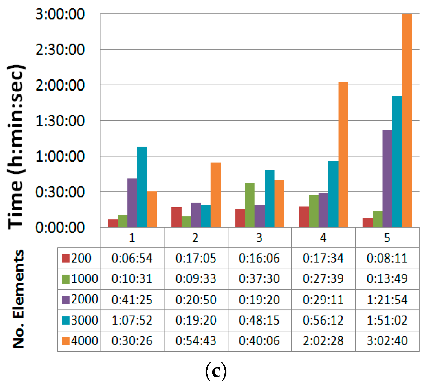
DEFORM F2™ allows choosing different levels of shape complexity and accuracy, offering a different range for the number of elements of the mesh. Higher defined values means more accurate final results from the simulation; however, the computation time will increase accordingly.
To determine the best combination of these parameters, and previously to the set of simulations planned, a brief study has been developed using a cross section reduction of RT = 0.5 and a die semiangle of α = 45°. The reason of choosing an intermediate situation is that DEFORM is a software specially designed to simulate metal forming operations; the study of the mesh is a key issue in other simulation programs of general purpose, being mandatory in these cases to realize a mesh sensitivity analysis. As the software used in this work includes a fully automatic, optimized remeshing algorithm, and direct extrusion of cylindrical billets is not a complex problem from a numerical point of view compared to other geometries (extrusion of complex profiles), the selection of accuracy and shape complexity parameters can be extrapolated to the other configurations and no important differences are expected to occur. Moreover, as explained before and indicated in the DEFORM user’s manual, the program implements a contact boundary condition with robust remeshing, so the mesh at the contact zone will be remeshed automatically in every case.
A moderate accuracy level and 3000 mesh elements have been determined as the best options because the central damage factors are similar to those obtained for higher levels (Figure 5a,b), and the computation times are adequate (Figure 5c).
The damage factor used by DEFORM F2™ is based on the Cockcroft-Latham criterion [27] and it establishes that fracture occurs in a ductile material when the integral in Equation (3) reaches a constant value, C, for a given temperature and strain rate
where is the maximum principal stress, is the equivalent strain, and is the equivalent strain to fracture. Damage in graphs specifies the damage factor at each element, Cf, and it is defined as
where is the effective stress. The damage factor is a non-dimensional parameter and can be used to predict fracture in cold forming operations [25].
2.2. Finite Element Model Validation
In order to validate the finite element model developed in DEFORM F2™, some results are going to be compared to the ones obtained by Soyarslan [23]. To this aim, the extrusion forces to extrude a billet of Cf53 steel (UNS G10550) are calculated for a double-pass die. This steel is an unalloyed high carbon steel with high stability and hardness, low deformation, and good wear resistance; the geometrical dimensions of the billet and the double-pass die are presented in Figure 6.
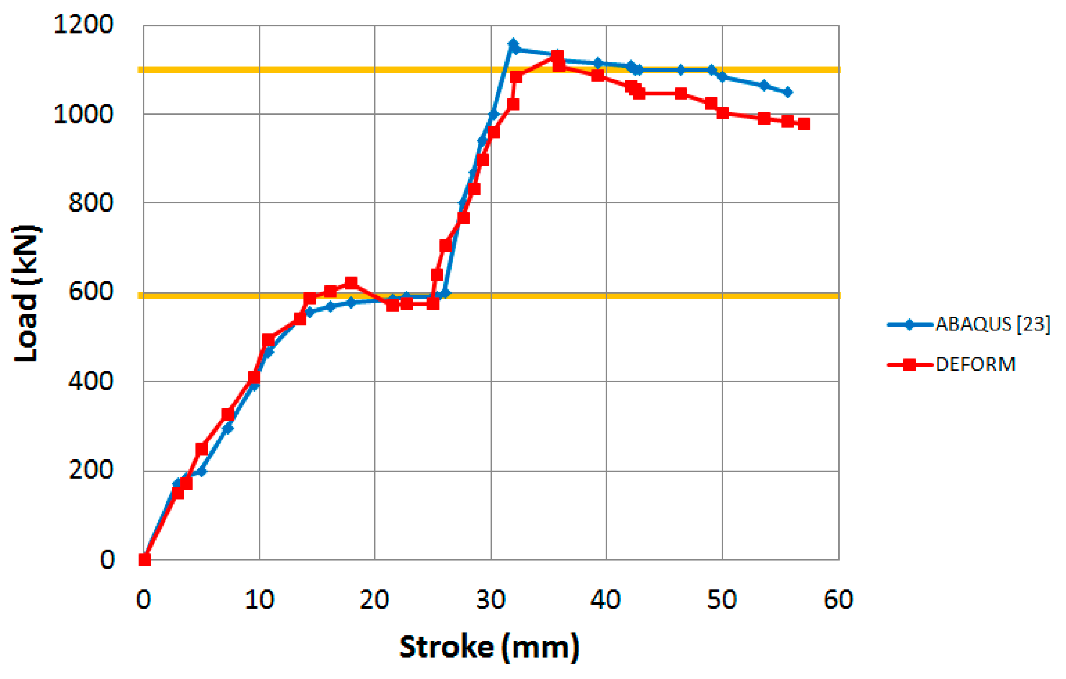
The extrusion force versus the ram stroke is represented in Figure 7 and compared to the work of Soyarslan [23]. The extrusion force at the first pass reaches the value of 600 kN; followed by a second pass where the maximum force reached is around 1100 kN.
Effective strain distributions and deformation pattern (Figure 8) in different stages of the simulation have also been compared to the ones presented in [23], having a perfect concordance; maximum residual strains are reached at the surface, and the deformation pattern at the die exit is the same.
Results are in good agreement with those obtained in [23], so the finite element model is considered validated.
3. Results and Discussion
3.1. Single-Pass Dies
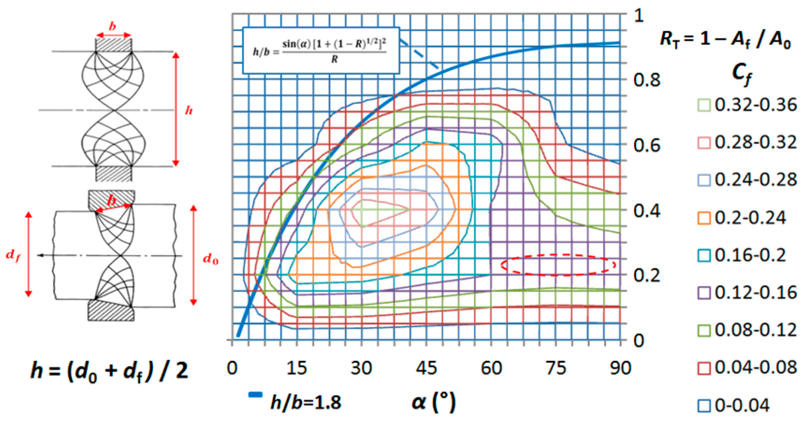
Results of damage factors for single-pass dies are shown in Figure 9 as a function of RT and α for a friction factor of m = 0.08. This is the value suggested by DEFORM for a general cold forming operation. To confirm that this value is in accordance to the industrial practice of extrusion of steels, we have checked that this value is also in the range of values found for the shear factor, m, obtained from double cup backward extrusion tests conducted in steels at room temperature and presented in [28]. Concretely, the values are in the range: 0.035 < m < 0.075 for different steels and lubrication systems, so the value m = 0.08 can be considered acceptable as a reference value where no lubrication system is defined, as in the case of this paper.
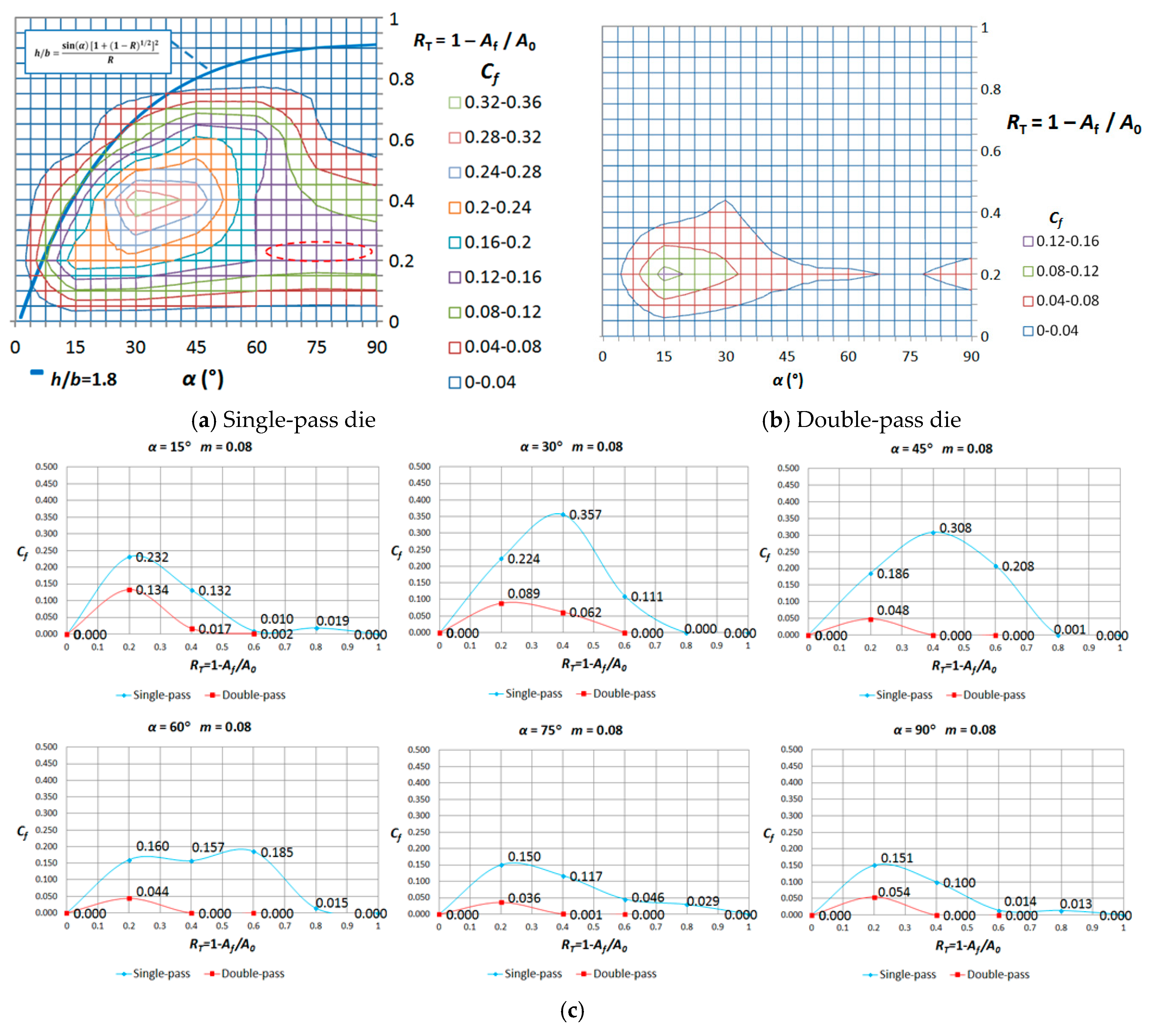
In indentation the non-homogeneity in forming causes secondary stresses and they depend on the ratio h/b, h being the height of the workpiece and b the width of the punch in contact with the workpiece. According to previous work about extrusion [21], the hydrostatic stress becomes positive and so leads to fracture, when h/b reaches the value 1.8. The theoretical limit of formability described by the hydrostatic stress criterion can be approached by the equation indicated in Figure 9 (blue curve), that represents the combination of cross-section reduction and die semiangle where h/b = 1.8. Considering this, central burst is not expected to appear to the left of the curve, whereas it could take place to the right depending of the microstructural characteristics.
The most damaged zones are located in the range of reductions 0.2 < RT < 0.6 and die semiangles 15° < α < 55°. For the highest semiangles (60° < α < 90°) damage becomes constant due to the dead zone appearance. Avitzur explained this effect in his work from 1968 [29], concluding that at high semiangles the dead zone formation is energetically more favorable than the central burst appearance and then the extrusion force experiences an asymptotic behavior (Figure 10a).
Additionally, as an example of friction influence on damage appearance, results have been analyzed for α = 30°. As it can be seen in Figure 10b, the maximum damage factor is expected when there is not friction at the contact surfaces, and the damage diminishes when the friction factor increases.
3.2. Double-Pass Dies
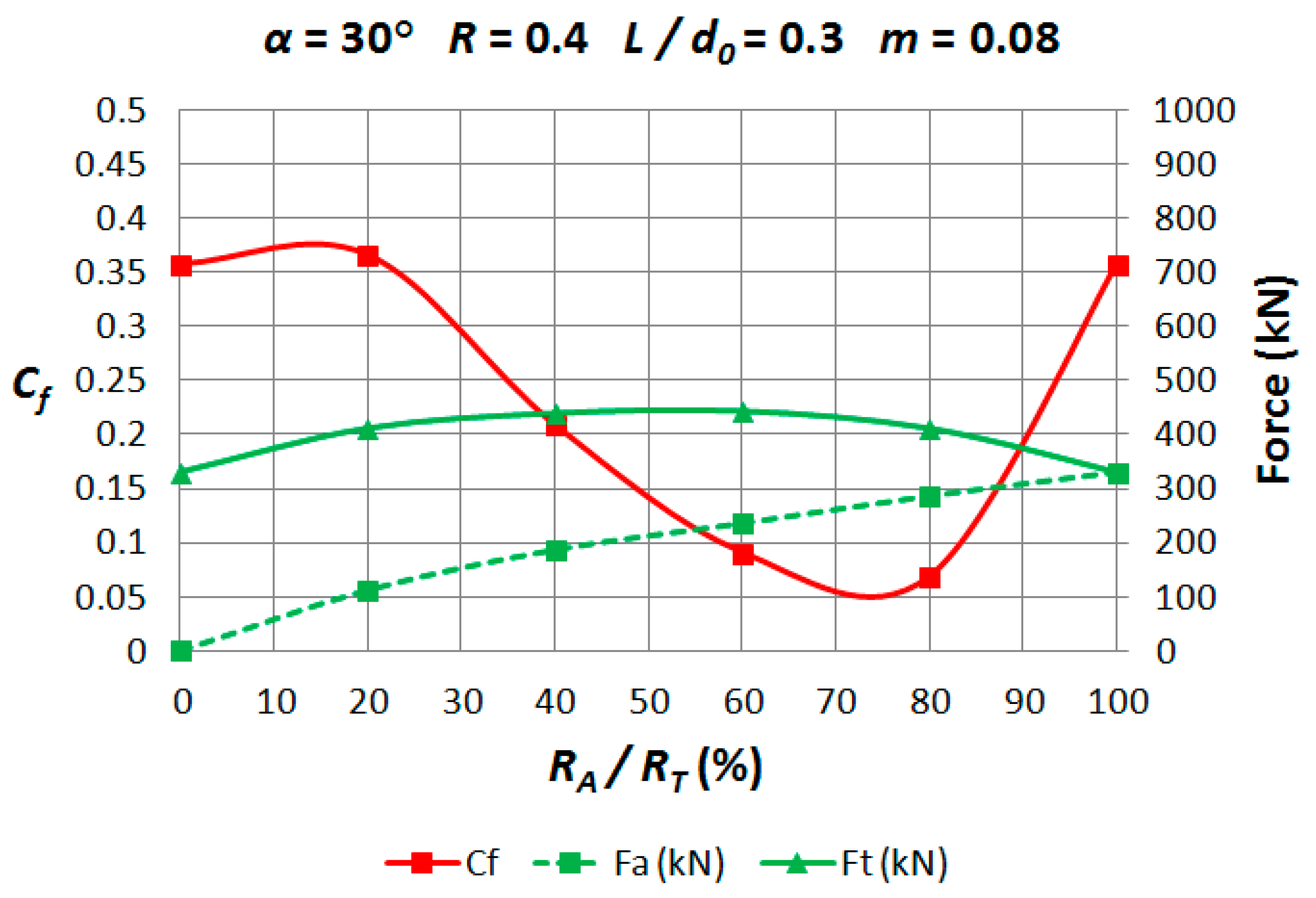
In Figure 11, damage factor curves and extrusion forces are represented in the range 0% < RA/RT < 100% for L/d0 = 0.3. The extrusion force is divided into two levels: the green dashed line is the force required to extrude the billet through the first pass, whereas the continuous line shows the total extrusion force. As expected, both lines are coincident when RA/RT = 100%, as it is the same case than a single-pass die. The red line shows the central damage behavior with RA. Again, this curve has the same values at RA/RT = 0% and RA/RT = 100% because it is a single-pass situation.
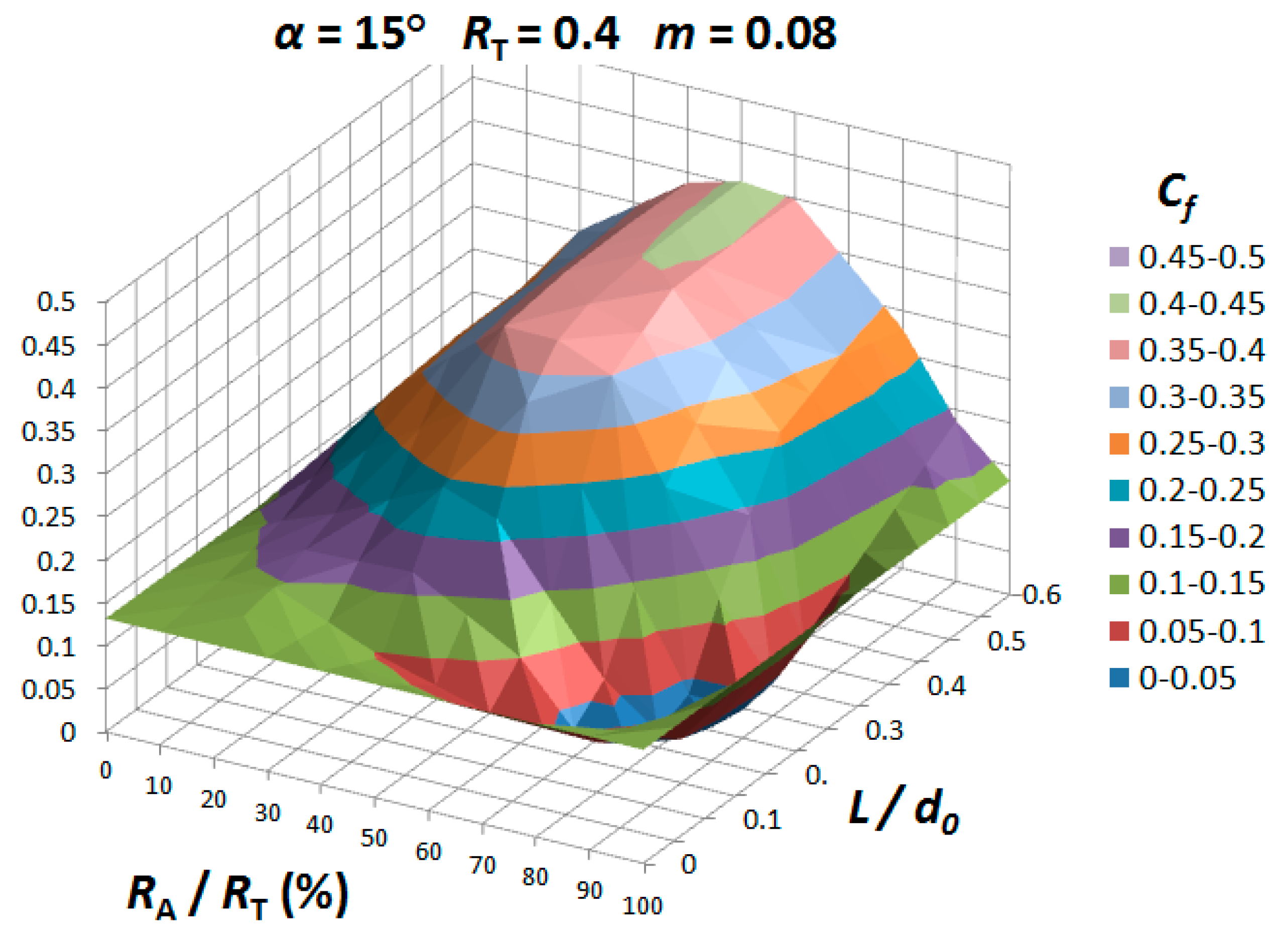
As an example of the results obtained, the behavior of damage factor with RA and L is presented in Figure 12 for a particular case (α = 15°, RT = 0.4, m = 0.08).
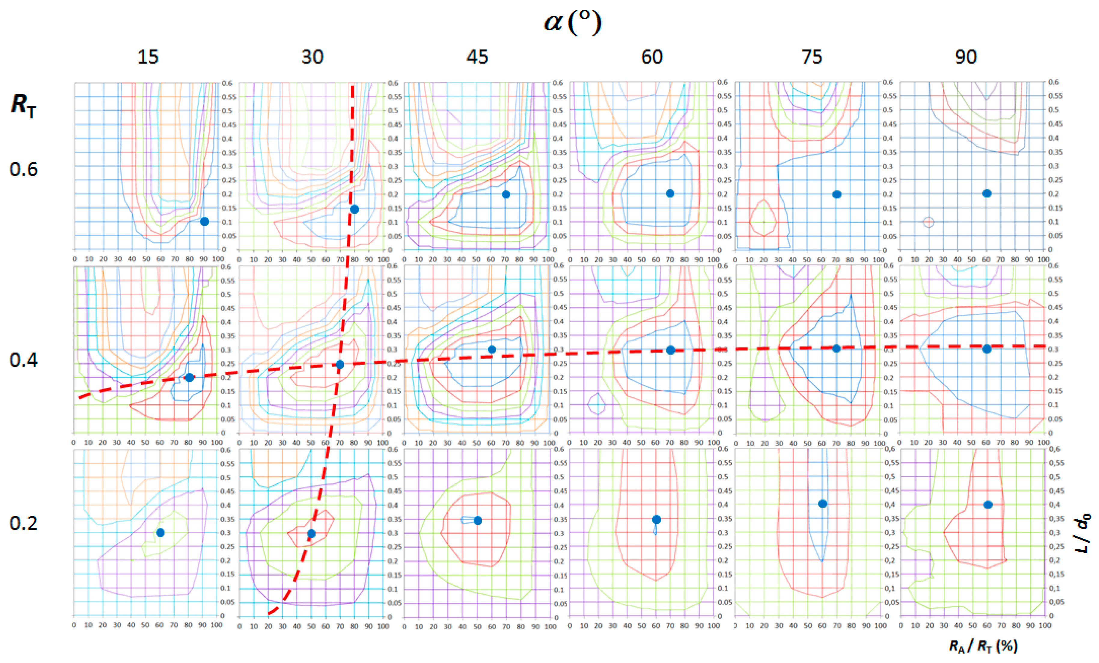
According to Figure 12, all the cases where L/d0 = 0, RA/RT = 0% and RA/RT = 100% show the same values of damage factors as they represent the single-pass extrusion. Generally speaking, as the length L grows, the central damage factor also increases; however, there is an intermediate zone where the central damage is minimum and this is the most interesting area of the graph because it shows the optimal geometrical configurations in order to reduce damage in the final part. Figure 13 sums up the results in two-dimensional graphs, using the same scale than in Figure 12, and showing the central damage factors contours versus RA/RT and L/d0 for each total reduction and semiangle. Simulations of double-pass extrusions have not been realized for a total reduction of RT = 0.8 because damage is low for all the semiangles in single-pass extrusion.
In each graph of Figure 13, a blue point indicating the absolute minimum has been included; the position of the minimum damage factor moves to higher values of L as the semiangle increases and to lower values of RA as the total reduction diminishes (show dashed red lines in Figure 13).
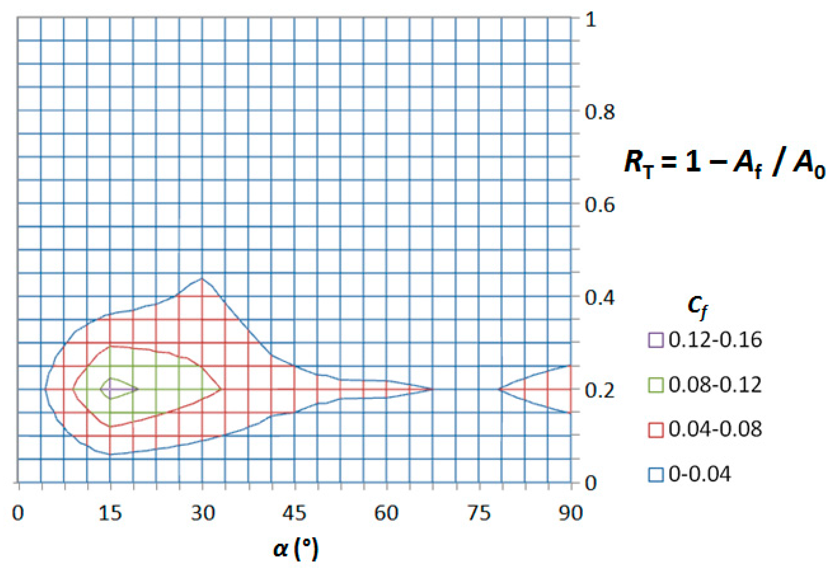
Gathering in a graph the minimum points (points in blue) corresponding to each semiangle and total reduction, a new central damage factors map can be depicted (Figure 14), and these values of damage are much lower than the ones represented in Figure 9 for a single-pass die.
The decrease of the central damage in the new map for double-pass extrusions (Figure 14) can contribute to avoiding central burst appearance for the whole range of values.
Based in Figure 13, the best geometrical configurations of double-pass dies (blue points) defined by RA/RT and L/d0, are summarized in Figure 15 for each combination of RT and α considered in this study.
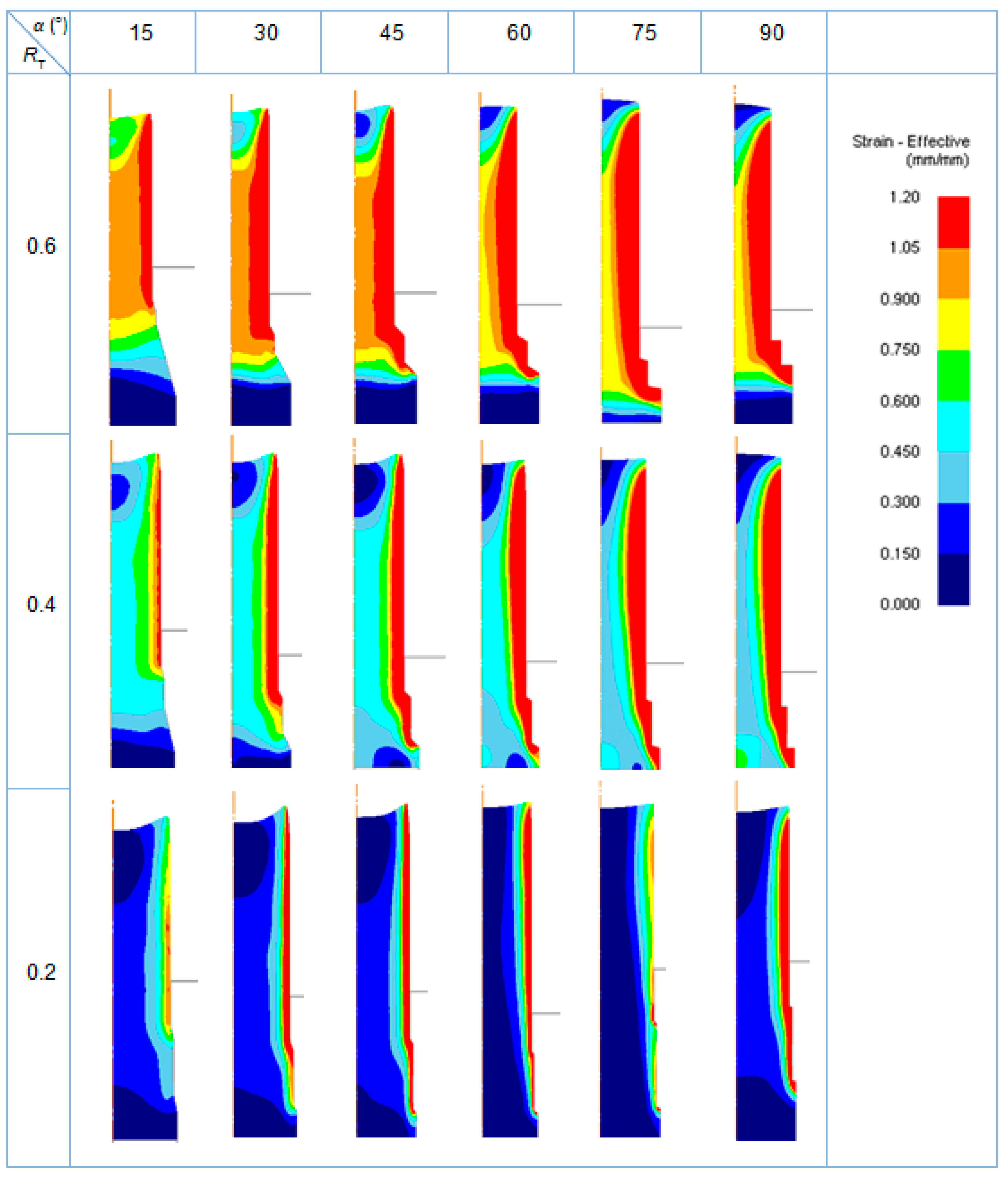
Effective strain distributions have been also obtained for the best configurations, and they are presented with the same scale in Figure 16.
As expected, the highest values of strains are obtained for the highest total reduction (RT = 0.6). For the same value of total reduction, the higher die semiangle, the higher the strains at the surface of the final part. The deformation pattern at the die exit changes, showing a dependency with the geometrical conditions.
In order to show the degree of agreement of the deformation pattern, a comparison with the case considered in the validation subsection has been developed (Figure 17), considering the steel DP800.
According to Figure 17, the deformation pattern presents a good degree of agreement as the profile of the workpiece at the die exit is coincident and the strain distributions show the maximum values of strain at the surface, and a minimum at the centerline.
3.3. Single-Pass Dies vs. Double-Pass Dies
In order to clearly show the reduction of central damage reached by the use of double-pass dies, a comparison of the results for single-pass and double-pass dies is presented in this section.
In Figure 18a,b, central damage factors maps for both cases are presented in the same figure, together with some graphs (Figure 18c) that specify in detail the values of minimum damage factor reached for all the combinations of die semiangle and total reduction in both cases (single and double-pass dies).
According to this figure, we can appreciate that the minimum damage is reached with double-pass dies in all the cases, when compared with single-pass dies. In single-pass extrusion, a clear tendency of damage factor with die semiangle cannot be defined; whereas in double-pass extrusion, the higher the die semiangle, the lower the induced damage.
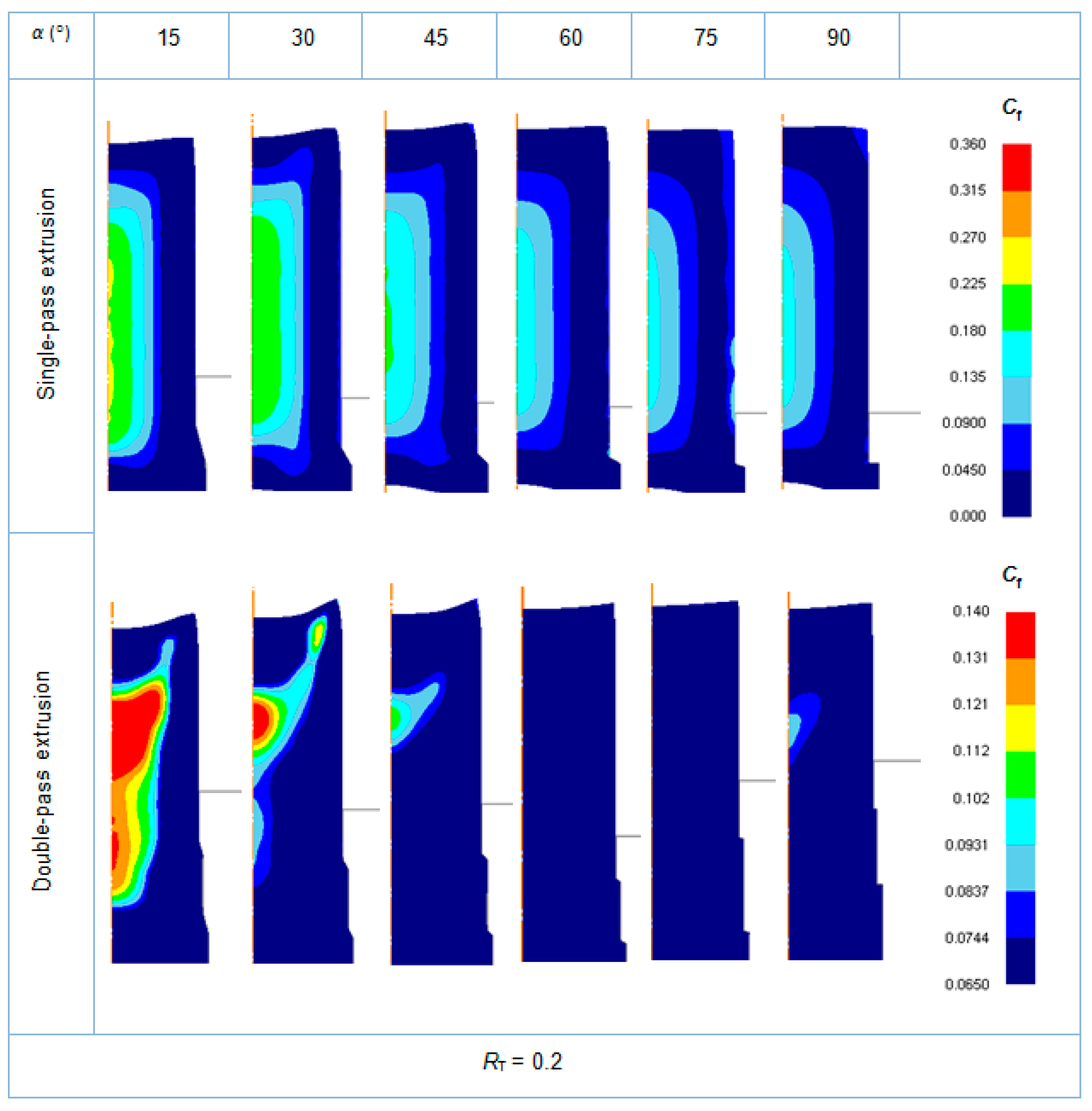
In Figure 19, Figure 20 and Figure 21, a comparison of induced damage distributions (considering the parameter damage factor) with single-pass dies vs. the best configurations of double-pass dies is presented.
A clear reduction of induced central damage is achieved with a change in the geometrical design of the die. This is a really important observation from an industrial point of view, because the final product of the extrusion process can significantly improve its quality and in-service behavior thanks to a change in the die design.
4. Conclusions and Future Work
In this work, the selection of the best geometrical configurations of double-pass dies is proposed as an alternative to single-pass extrusions in order to minimize the central damage that can lead to central burst in extruded parts. A methodology has been proposed using finite element simulation for the dual-phase steel DP800; around 500 simulations have been realized to take into account the combination of parameters in single and double-pass extrusions. Accordingly, some interesting conclusions have been extracted. First of all, simulation of single-pass extrusions was able obtain a map of central damage factors depending on the die semiangle and the total cross-section reduction, and it is consistent with the hydrostatic stress criterion. Simulations demonstrate that friction phenomenon reduces central damage. In double-pass extrusions, for each pair (RT, α), there are combinations of RA and L that cause a minimum value of damage, even lower than the one obtained in single-pass extrusions. Choosing these two parameters (RA and L), which means selecting the best die design, it is possible to perform an extrusion where central damage is significantly reduced compared to single extrusion, as it has been shown through all the induced damage diagrams and central damage factors maps presented when comparing single and double-pass dies extrusions. These kinds of maps are quite useful to avoid defective products in industrial practice, as for example, forming limit diagrams typically used in sheet metal forming.
Therefore, in this paper, the best designs of die geometry to reduce central damage have been determined. This is a really important contribution from an industrial point of view, because the final product of the extrusion process can significantly improve its quality and in-service behavior thanks to a change in the die design.
As a general rule, the position of the minimum damage leads to choose higher values of L for high semiangles and to lower values of RA for low total reductions.
In this paper, as a preliminary work in this field, we have focused on considering the most general conditions in a cold extrusion process of a particular dual-phase steel in order to determine if it is possible to establish a general trend in the reduction of damage when modifying the most relevant parameters; once it has been demonstrated by the results presented in the paper, and given that there are other parameters affecting the results, future work should be done to optimize the process, by searching for the most appropriate combination of parameters that leads to the best results (considering not only geometrical parameters, but also operating conditions and microstructural and tribological aspects); for example, taking into account different die semiangles in each pass and/or friction conditions, or analyzing the effect of this complex microstructure. In this regard, micromechanical modeling of damage is one promising research field; the use of 3D simulation software will be highly recommended in view of the results of Ayatollahi et al. [18], in order to accurately reproduce the different phases and their distribution in the microstructure of the workpiece. 3D finite element modelling will be also required in the case of analysis of extrusions of asymmetrical parts, where 2D modelling is not suitable.
Additionally, we think this methodology can be used to determine the optimal configuration of multiple-pass dies for other AHSS, whose formability currently under study.
Acknowledgments
This work has been financially supported by funds provided through the Annual Grant Call of the E.T.S.I.I. of UNED of reference 2017-ICF04 and the Department of Construction and Manufacturing Engineering of UNED. The authors would like to take this opportunity to thank the Research Group of the UNED “Industrial Production and Manufacturing Engineering (IPME)” for the support provided during the development of this work.
Author Contributions
Ana María Camacho conceived the problem; Francisco Javier Amigo designed the cases to be analyzed and performed the finite element simulations; Ana María Camacho and Francisco Javier Amigo analyzed the results; Francisco Javier Amigo wrote the paper.
Conflicts of Interest
The authors declare no conflict of interest.
References
- Bhargava, M.; Tewari, A.; Mishra, S.K. Forming limit diagram of advanced high strength steels (AHSS) based on strain-path diagram. Mater. Des. 2015, 85, 149–155. [Google Scholar] [CrossRef]
- Del Pozo, D.; López de Lacalle, L.N.; López, J.M.; Hernández, A. Prediction of press/die deformation for an accurate manufacturing of drawing dies. Int. J. Adv. Manuf. Technol. 2008, 37, 649–656. [Google Scholar] [CrossRef]
- López de Lacalle, L.N.; Lamikiz, A.; Muñoa, J.; Sánchez, J.A. The cam as the centre of gravity of the five-axis high speed milling of complex parts. Int. J. Prod. Res. 2005, 43, 1983–1999. [Google Scholar] [CrossRef]
- López de Lacalle, L.N.; Lamikiz, A.; Sánchez, J.A. Improving the high-speed finishing of forming tools for advanced high-strength steels (ahss). Int. J. Adv. Manuf. Technol. 2005, 29, 49–63. [Google Scholar] [CrossRef]
- Nasser, A.; Yadav, A.; Pathak, P.; Altan, T. Determination of the flow stress of five ahss sheet materials (DP 600, DP 780, DP 780-CR, DP 780-HY and TRIP 780) using the uniaxial tensile and the biaxial viscous pressure bulge (VPB) tests. J. Mater. Process. Technol. 2010, 210, 429–436. [Google Scholar] [CrossRef]
- Moeini, G.; Ramazani, A.; Myslicki, S.; Sundararaghavan, V.; Könke, C. Low cycle fatigue behaviour of DP steels: Micromechanical modelling vs. validation. Metals 2017, 7, 265. [Google Scholar] [CrossRef]
- Nam, W.J.; Bae, C.M. Microstructural evolution and its relation to mechanical properties in a drawn dual-phase steel. J. Mater. Sci. 1999, 34, 5661–5668. [Google Scholar] [CrossRef]
- Ramazani, A.; Kazemiabnavi, S.; Larson, R. Quantification of ferrite-martensite interface in dual phase steels: A first-principles study. Acta Mater. 2016, 116, 231–237. [Google Scholar] [CrossRef]
- Ramazani, A.; Mukherjee, K.; Schwedt, A.; Goravanchi, P.; Prahl, U.; Bleck, W. Quantification of the effect of transformation-induced geometrically necessary dislocations on the flow-curve modelling of dual-phase steels. Int. J. Plast. 2013, 43, 128–152. [Google Scholar] [CrossRef]
- Evin, E.; Tomáš, M. The influence of laser welding on the mechanical properties of dual phase and trip steels. Metals 2017, 7, 239. [Google Scholar] [CrossRef]
- Gutiérrez-Regueras, J.M.; Camacho, A.M. Investigations on the influence of blank thickness (t) and length/wide punch ratio (LD) in rectangular deep drawing of dual-phase steels. Comput. Mater. Sci. 2014, 91, 134–145. [Google Scholar] [CrossRef]
- García-Domínguez, A.; Claver, J.; Camacho, A.M.; Sebastián, M.A. Comparative analysis of extrusion processes by finite element analysis. Procedia Eng. 2015, 100, 74–83. [Google Scholar] [CrossRef]
- Parghazeh, A.; Haghighat, H. Prediction of central bursting defects in rod extrusión process with upper bound analysis method. Trans. Nonferrous Met. Soc. China 2016, 26, 2892–2899. [Google Scholar] [CrossRef]
- Camacho, A.M.; Gonzalez, C.; Rubio, E.M.; Sebastian, M.A. Influence of geometrical conditions on central burst appearance in axisymmetrical drawing processes. J. Mater. Process. Technol. 2006, 177, 304–306. [Google Scholar] [CrossRef]
- Oh, S.-I.; Walters, J.; Wu, W.-T. Finite element method applications in bulk forming. In ASM Handbook. Metals Process Simulation; Furrer, D.U., Semiatin, S.L., Eds.; ASM International: Materials Park, OH, USA, 2010; Volume 22B, pp. 267–289. ISBN 978-1-61503-005-7. [Google Scholar]
- Pathak, N.; Butcher, C.; Worswick, M.J.; Bellhouse, E.; Gao, J. Damage evolution in complex-phase and dual-phase steels during edge stretching. Materials 2017, 10, 346. [Google Scholar] [CrossRef] [PubMed]
- Tasan, C.C.; Hoefnagels, J.P.M.; Diehl, M.; Yan, D.R.F.; Raabe, D. Strain localization and damage in dual phase steels investigated by coupled in-situ deformation experiments and crystal plasticity simulations. Int. J. Plast. 2014, 63, 198–210. [Google Scholar] [CrossRef]
- Ayatollahi, M.R.; Darabi, A.C.; Chamani, H.R.; Kadkhodapour, J. 3D micromechanical modeling of failure and damage evolution in dual phase steel based on a real 2D microstructure. Acta Mech. Solida Sin. 2016, 29, 95–110. [Google Scholar] [CrossRef]
- Tekkaya, A.E.; Khalifa, N.B.; Hering, O.; Meya, R.; Myslicki, S.; Walther, F. Forming-induced damage and its effects on product properties. CIRP Ann. Manuf. Technol. 2017, 66, 281–284. [Google Scholar] [CrossRef]
- Dieter, G.E.; Kuhn, H.A.; Semiatin, S.L. Handbook of Workability and Process Design; ASM International: Materials Park, OH, USA, 2003; ISBN 978-0-87170-778-9. [Google Scholar]
- Reddy, N.V.; Dixit, P.M.; Lal, G.K. Ductile fracture criteria and its prediction in axisymmetric drawing. Int. J. Mach. Tool Manuf. 2000, 40, 95–111. [Google Scholar] [CrossRef]
- Reddy, N.V.; Dixit, P.M.; Lal, G.K. Central bursting and optimal die profile for axisymmetric extrusion. J. Manuf. Sci. Eng.-Trans. ASME 1996, 118, 579–584. [Google Scholar] [CrossRef]
- Soyarslan, C. Modelling Damage for Elastoplasticity. Ph.D. Thesis, Middle East Technical University, Çankaya Ankara, Turkey, 2008. [Google Scholar]
- Wagener, H.W.; Haats, J. Crack prevention and increase of workability of brittle materials by cold extrusion. Stud. Appl. Mech. 1995, 43, 373–386. [Google Scholar]
- Scientific Forming Technologies Corporation. DEFORM-F2 v11.0 User’s Manual; Scientific Forming Technologies Corporation: Columbus, OH, USA, 2014. [Google Scholar]
- Kalpakjian, S.; Schmid, S.R. Manufacturing Engineering and Technology, 7th ed.; Pearson: Mexico, 2014; ISBN 978-0133128741. [Google Scholar]
- Cockcroft, M.; Latham, D. Ductility and the workability of metals. J. Inst. Met. 1968, 96, 33–39. [Google Scholar]
- Gariety, M.; Ngaile, G. Cold and Hot Forging. Fundamentals and Applications; ASM International: Materials Park, OH, USA, 2005. [Google Scholar]
- Avitzur, B. Analysis of central bursting defects in extrusion and wire drawing. J. Eng. Ind. 1968, 90, 79–91. [Google Scholar] [CrossRef]
Figure 1.
Scheme of single and double-pass extrusions showing strain rate contour diagrams by FEA (finite element analysis).
Figure 1.
Scheme of single and double-pass extrusions showing strain rate contour diagrams by FEA (finite element analysis).

Figure 2.
Flow curve of dual-phase steel DP800.

Figure 3.
Geometrical definition of double-pass die.
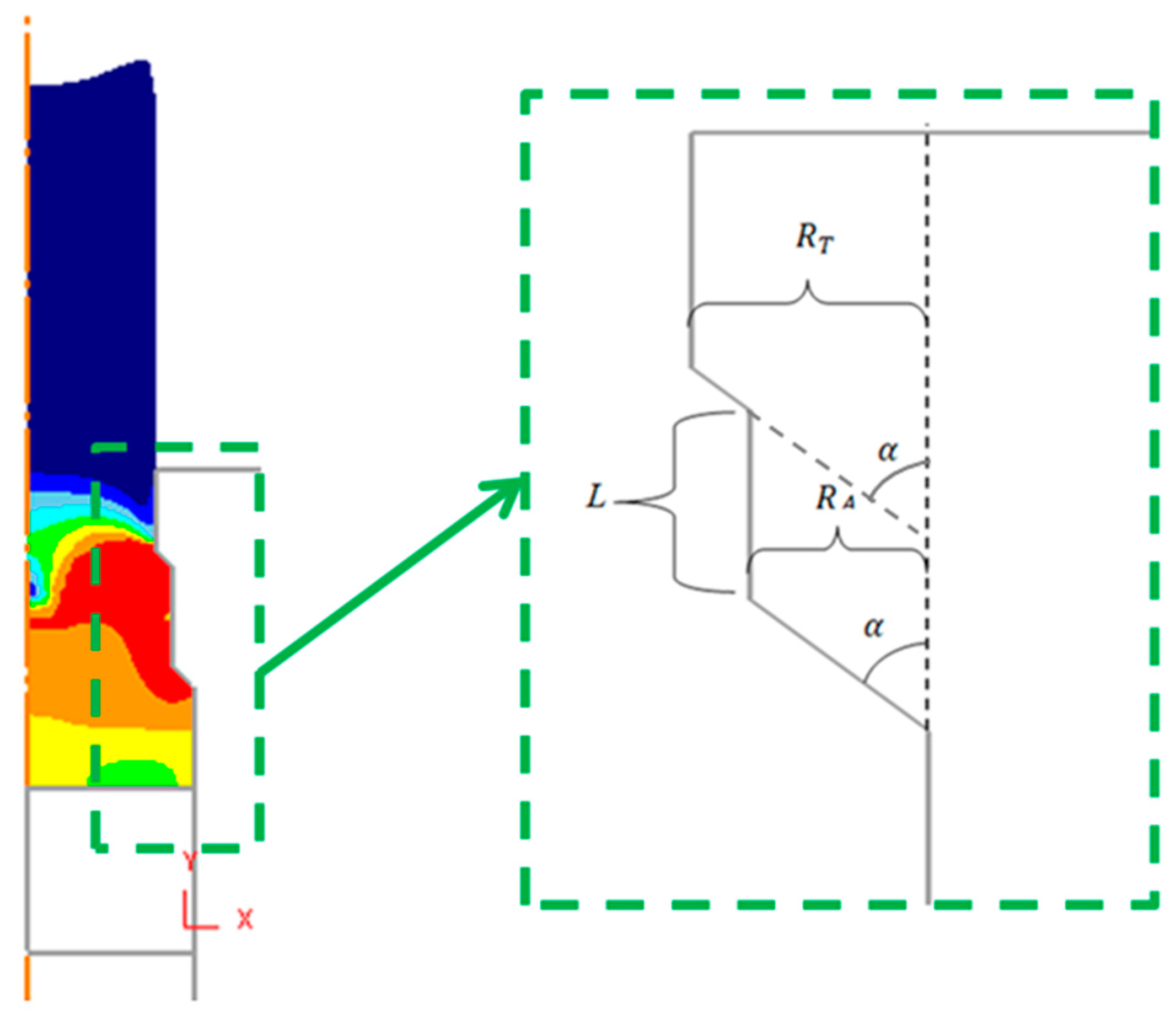
Figure 4.
Mesh and geometrical configuration at the initial step before extrusion starts (α = 30°, RT = 0.6, RA/RT = 60%, L/d0 = 0.4).
Figure 4.
Mesh and geometrical configuration at the initial step before extrusion starts (α = 30°, RT = 0.6, RA/RT = 60%, L/d0 = 0.4).
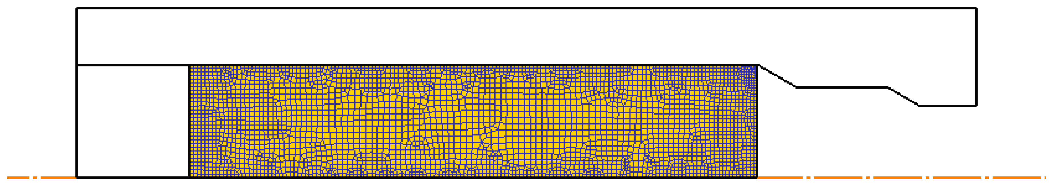
Figure 5.
(a) Selection of number of elements of the mesh; (b) Selection of the accuracy level; (c) Computation times.
Figure 5.
(a) Selection of number of elements of the mesh; (b) Selection of the accuracy level; (c) Computation times.
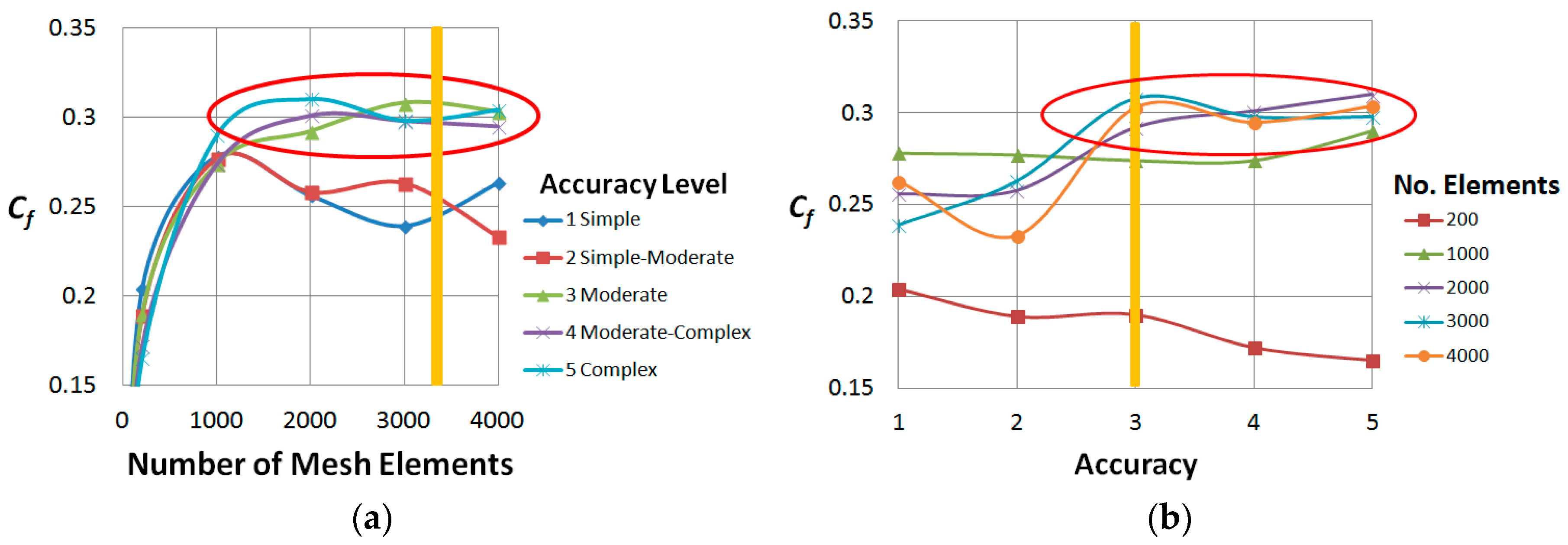

Figure 6.
Mesh and geometrical details defined in [23].
Figure 6.
Mesh and geometrical details defined in [23].
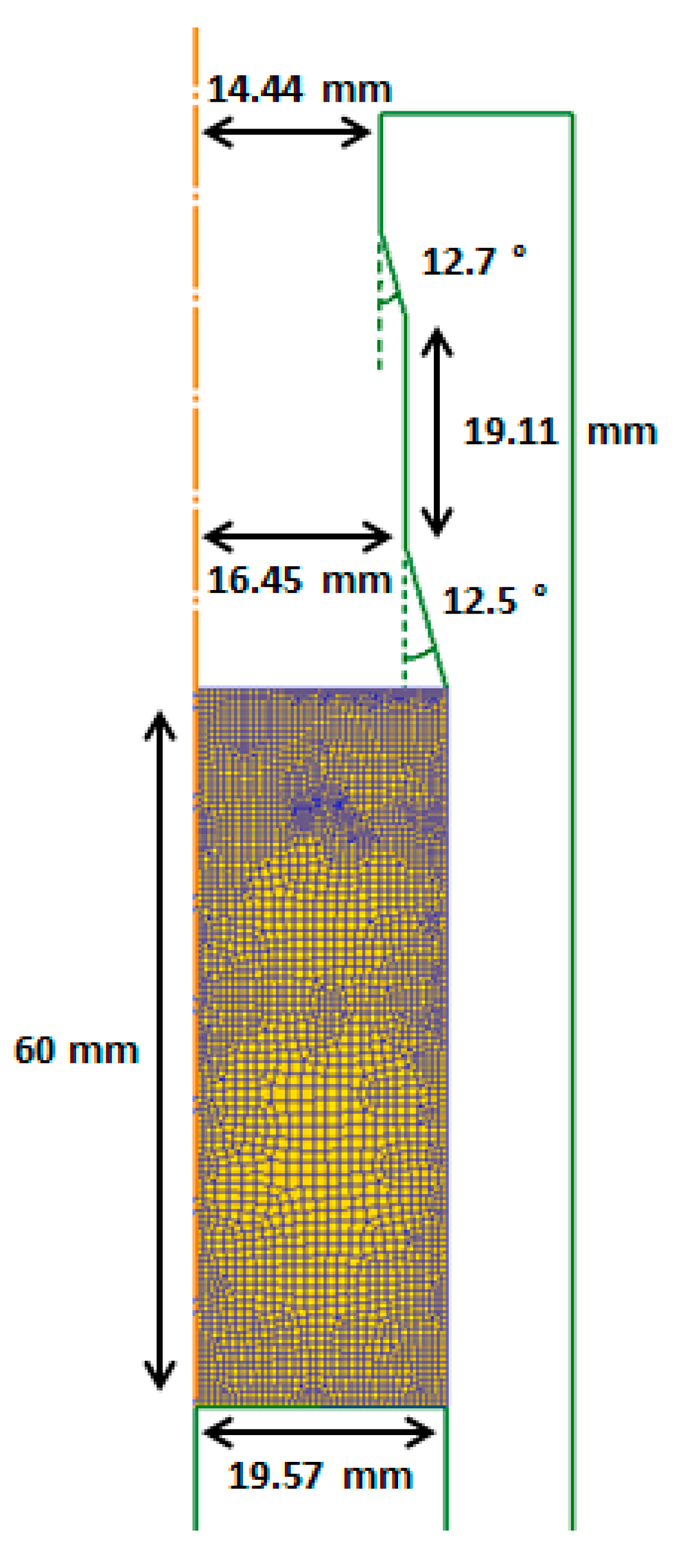
Figure 7.
Extrusion force in a double-pass extrusion for Cf53 steel obtained by the finite element software ABAQUS [23] and DEFORM-F2. Yellow horizontal lines show approximate values of the maximum forces required to extrude the workpiece in each pass.
Figure 7.
Extrusion force in a double-pass extrusion for Cf53 steel obtained by the finite element software ABAQUS [23] and DEFORM-F2. Yellow horizontal lines show approximate values of the maximum forces required to extrude the workpiece in each pass.

Figure 8.
Effective strain distributions in different stages of the simulation used in the validation of the finite element model.
Figure 8.
Effective strain distributions in different stages of the simulation used in the validation of the finite element model.
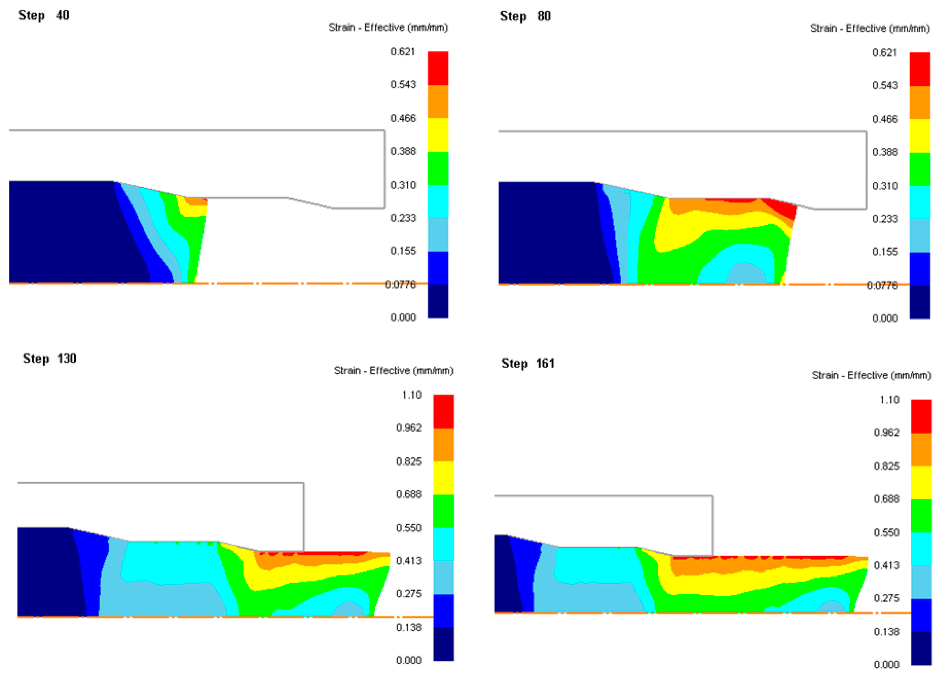
Figure 9.
Central damage factors (Cf) map in single-pass extrusion of dual-phase steel DP800 for m = 0.08 and theoretical limit of central burst appearance (blue curve) according to [21].
Figure 9.
Central damage factors (Cf) map in single-pass extrusion of dual-phase steel DP800 for m = 0.08 and theoretical limit of central burst appearance (blue curve) according to [21].

Figure 10.
(a) Extrusion force at different cross-section reductions for m = 0.08 and dead zone effect; (b) Central damage (Cf) versus cross-section reduction for α = 30° and different friction factors.
Figure 10.
(a) Extrusion force at different cross-section reductions for m = 0.08 and dead zone effect; (b) Central damage (Cf) versus cross-section reduction for α = 30° and different friction factors.
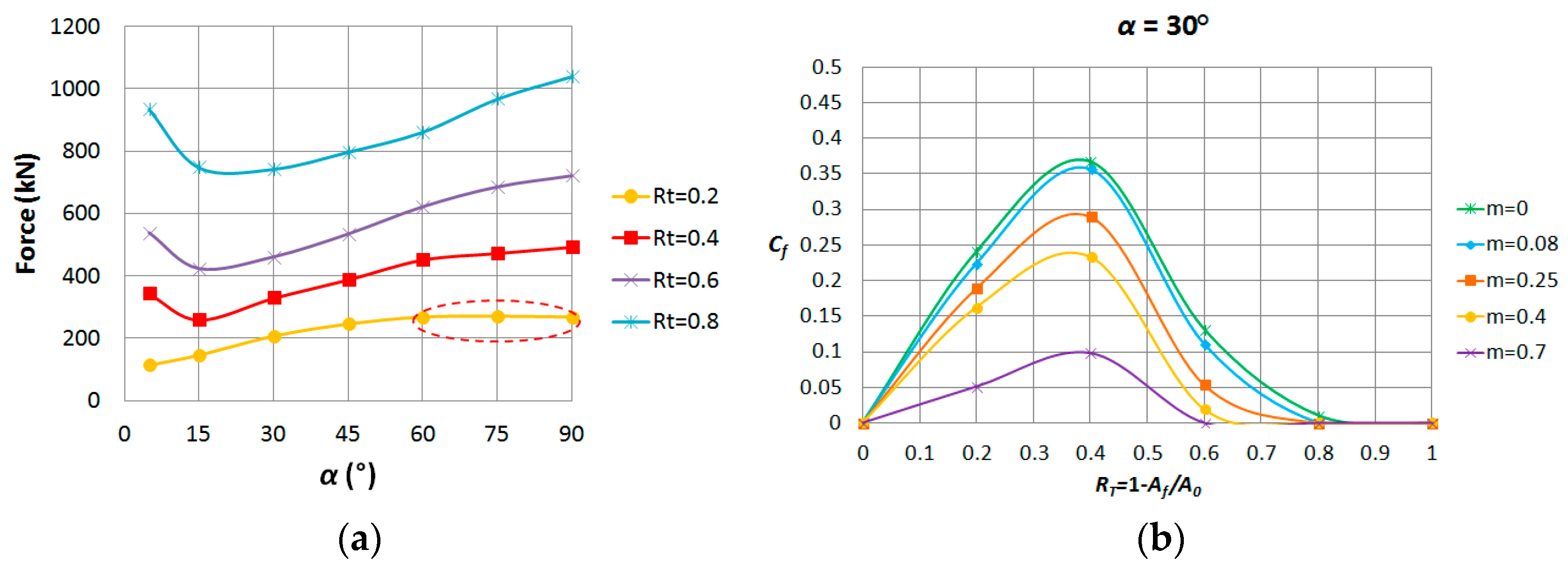
Figure 11.
Damage factors (Cf) and forces versus RA/RT.

Figure 12.
Surface of damage (Cf) as a function of L and RA.

Figure 13.
Contours of central damage factors (Cf) in double-pass extrusions and location of the point of minimum damage.
Figure 13.
Contours of central damage factors (Cf) in double-pass extrusions and location of the point of minimum damage.

Figure 14.
Central damage factors (Cf) map in double-pass extrusion of dual-phase steel DP800 for m = 0.08, showing the minimum values.
Figure 14.
Central damage factors (Cf) map in double-pass extrusion of dual-phase steel DP800 for m = 0.08, showing the minimum values.

Figure 15.
Summary of the best configurations of double-pass dies in cold extrusion of dual-phase steel DP800.
Figure 15.
Summary of the best configurations of double-pass dies in cold extrusion of dual-phase steel DP800.

Figure 16.
Effective strain diagrams for the best configurations of double-pass dies in cold extrusion of dual-phase steel DP800.
Figure 16.
Effective strain diagrams for the best configurations of double-pass dies in cold extrusion of dual-phase steel DP800.

Figure 17.
Comparison of strain distributions (RT = 45.55%, α ≅ 12.6° [23]); (a) Steel UNS G10550; (b) Steel DP800.
Figure 17.
Comparison of strain distributions (RT = 45.55%, α ≅ 12.6° [23]); (a) Steel UNS G10550; (b) Steel DP800.
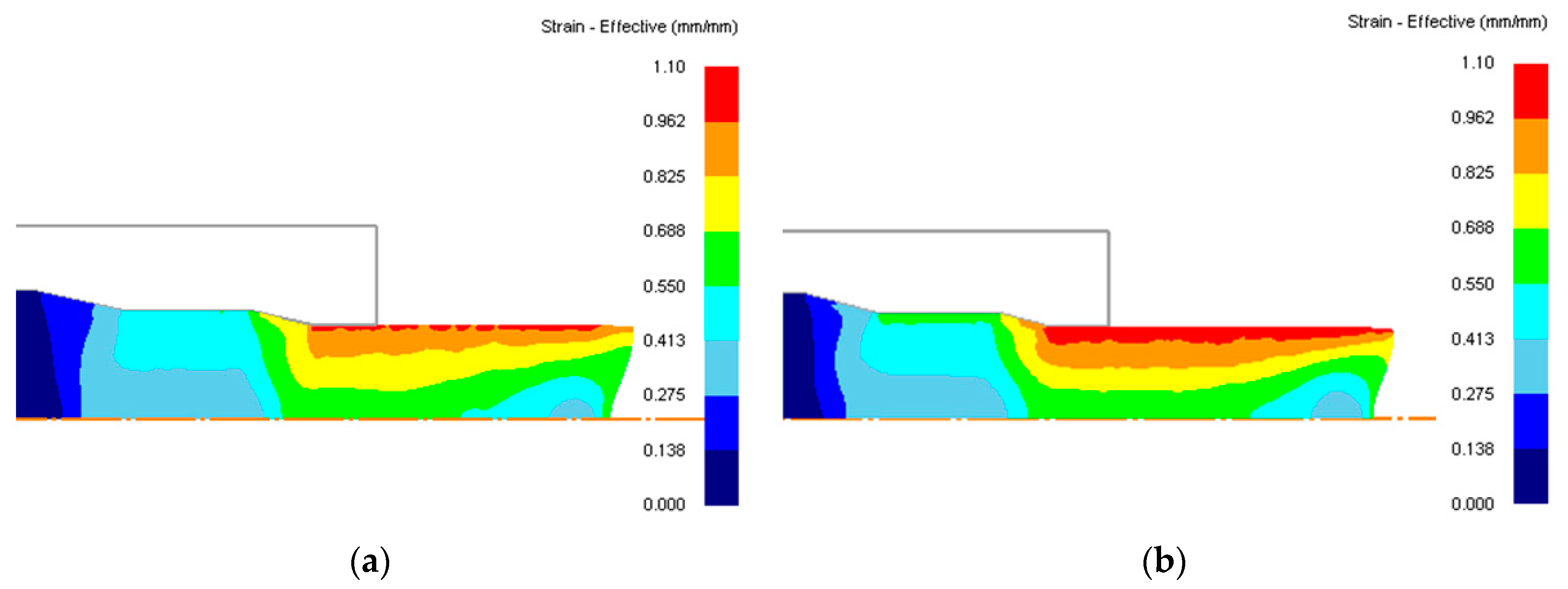
Figure 18.
Comparison of minimum damage (Cf) induced with (a) single-pass dies vs. (b) double pass dies in cold extrusion of dual-phase steel DP800. (c) Values of minimum damage factor reached for all the combinations of die semiangle and total reduction for single and double-pass dies.
Figure 18.
Comparison of minimum damage (Cf) induced with (a) single-pass dies vs. (b) double pass dies in cold extrusion of dual-phase steel DP800. (c) Values of minimum damage factor reached for all the combinations of die semiangle and total reduction for single and double-pass dies.

Figure 19.
Comparison of damage (Cf) induced with single-pass dies vs. the best configurations of double-pass dies with RT = 0.6.
Figure 19.
Comparison of damage (Cf) induced with single-pass dies vs. the best configurations of double-pass dies with RT = 0.6.
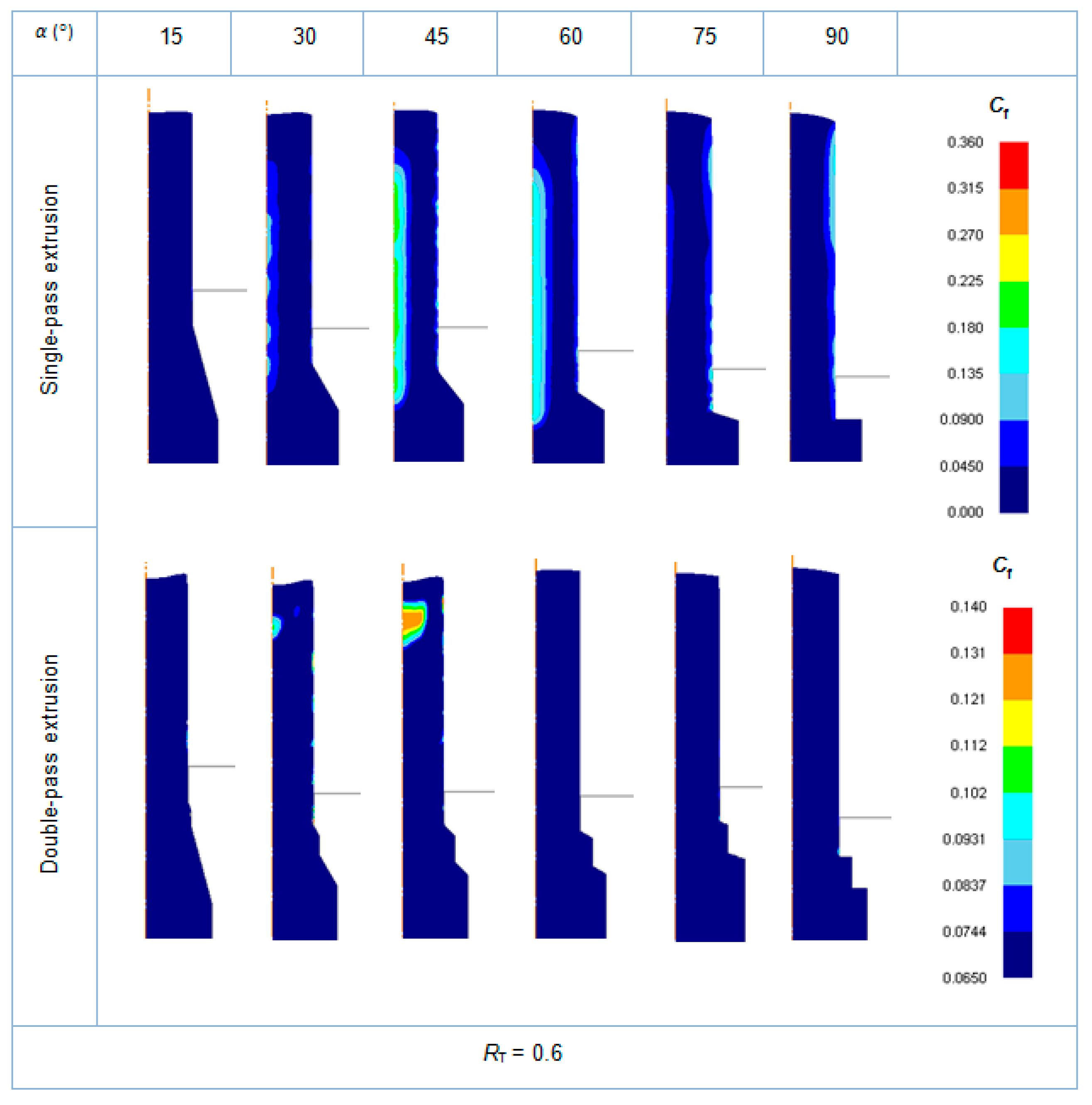
Figure 20.
Comparison of damage (Cf) induced with single-pass dies vs. the best configurations of double-pass dies with RT = 0.4.
Figure 20.
Comparison of damage (Cf) induced with single-pass dies vs. the best configurations of double-pass dies with RT = 0.4.
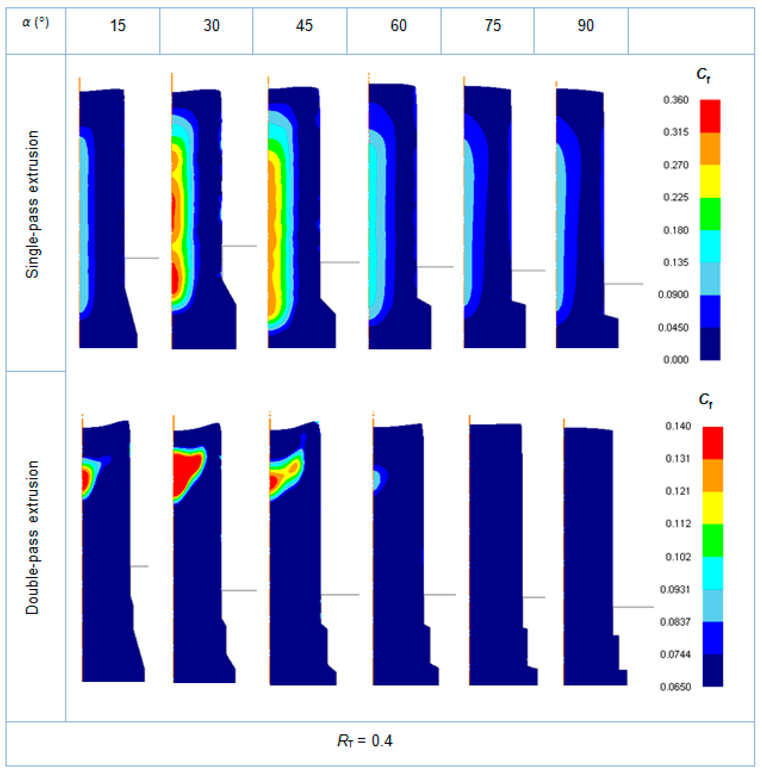
Figure 21.
Comparison of damage (Cf) induced with single-pass dies vs. the best configurations of double-pass dies with RT = 0.2.
Figure 21.
Comparison of damage (Cf) induced with single-pass dies vs. the best configurations of double-pass dies with RT = 0.2.


Table 1.
Die semi-angles in extrusions with single-pass dies (α).
| α (°) | |||||
|---|---|---|---|---|---|
| 15 | 30 | 45 | 60 | 75 | 90 |
Table 2.
Cross-section reductions in extrusions with single-pass dies (RT).
| RT | |||
|---|---|---|---|
| 0.2 | 0.4 | 0.6 | 0.8 |
Table 3.
Cross-section reductions in the first pass relative to the total reduction (RA/RT).
| RA/RT | |||||
|---|---|---|---|---|---|
| 0.0 | 0.2 | 0.4 | 0.6 | 0.8 | 1.0 |
Table 4.
Non-dimensional length (L/d0) in extrusions with double-pass dies.
| L/d0 | ||||||
|---|---|---|---|---|---|---|
| 0.0 | 0.1 | 0.2 | 0.3 | 0.4 | 0.5 | 0.6 |
© 2017 by the authors. Licensee MDPI, Basel, Switzerland. This article is an open access article distributed under the terms and conditions of the Creative Commons Attribution (CC BY) license (http://creativecommons.org/licenses/by/4.0/).
Share and Cite
MDPI and ACS Style
Amigo, F.J.; Camacho, A.M. Reduction of Induced Central Damage in Cold Extrusion of Dual-Phase Steel DP800 Using Double-Pass Dies. Metals 2017, 7, 335. https://doi.org/10.3390/met7090335
AMA Style
Amigo FJ, Camacho AM. Reduction of Induced Central Damage in Cold Extrusion of Dual-Phase Steel DP800 Using Double-Pass Dies. Metals. 2017; 7(9):335. https://doi.org/10.3390/met7090335
Chicago/Turabian StyleAmigo, Francisco Javier, and Ana María Camacho. 2017. "Reduction of Induced Central Damage in Cold Extrusion of Dual-Phase Steel DP800 Using Double-Pass Dies" Metals 7, no. 9: 335. https://doi.org/10.3390/met7090335
Note that from the first issue of 2016, this journal uses article numbers instead of page numbers. See further details here.