Behavior of the Steel T91 under Multi Axial Loading in Contact with Liquid and Solid Pb


1
Department of R&D for Generation IV Technologies, Centrum Vyzkumu Rez (CVR), Rez 130, 25068 Husinec, Czech Republic
2
Department of Materials Science, Institute of Plasma Physics of the Czech Academy of Science (IPP), 18200 Prague, Czech Republic
*
Author to whom correspondence should be addressed.
Metals 2017, 7(9), 342; https://doi.org/10.3390/met7090342
Submission received: 2 August 2017
/
Revised: 21 August 2017
/
Accepted: 22 August 2017
/
Published: 4 September 2017
(This article belongs to the Special Issue Fracture Behaviour of Innovative Materials under Different Enviromental Conditions)
Abstract
:In this work, the conditions for the occurrence of Liquid Metal Embrittlement (LME) in the ferritic-martensitic steel T91 in contact with lead, Pb, were examined. Slow tensile tests with notched specimens revealed that in a temperature range close to the melting point of Pb, the steel is sensitive to LME (350–400 °C) and to Solid Metal Induced Embrittlement (SMIE) (300 °C). The cracking was stimulated by wetting (using a chemical flux) and the notch effect. It was found that the multi axial stresses state and the high level of plastic strain in front of the notch were the key factors triggering crack initiation.
1. Introduction
The interaction between structural materials and coolant is one of the most critical issues in the development of Lead cooled Fast Reactors (LFR). The ferritic-martensitic steel, T91, is among the candidate materials for fast reactors and its behavior in liquid Pb is a subject of great interest for the research community. In the temperature range between 350 and 550 °C, which are relevant for LFR, the liquid metal embrittlement (LME) and the surface oxidation/dissolution are being studied among the most relevant degradation mechanisms.
LME is the tendency of structural materials to low energy fracture under stress in contact with liquid metals; the phenomenon is typically associated with a change from ductile to a cleavage-like fracture mode. LME is usually most severe just above the melting point of the liquid metal and it disappears with increasing temperature [1]. The embrittlement can occur even under the melting temperature of the liquid metal. The Solid Metal Induced Embrittlement (SMIE) is much less severe than the LME [2], even if it has the same microstructural features.
Beside the temperature, the formation of oxide scales is very important, because wetting of the material surface by liquid metal was found to be the pre-condition for the LME susceptibility [3]. The optimal oxygen concentration to grow stable and protective oxide scales on the T91 steel was evaluated to be about 10−6 wt. % at 500 °C [4,5,6], which may slightly change as a function of temperature. The protective oxide layer prevents initiation of any kind of degradation, including dissolution and LME. However, long-term exposure to heavy liquid metals or mechanical and thermo-cycling effects may cause damage and induce failure of oxides. In this case, either the steel is able to self-heal the damage by further growth of oxides (most likely at higher temperatures), or the damage starts locally and dissolution or LME are observed.
Most of the data about LME were being studied in Pb–Bi eutectic. However, there is much less work on the interaction of steels with pure Pb. In fact, because of the different chemistry and range of temperatures (higher), this media has a different impact on the materials behavior.
The first part of this research [7] was aimed to study the behavior of the T91/Pb interaction under load and to identify the conditions leading to the LME. The three parameters that were selected were temperature, deformation rate and surface treatment in order to stimulate the LME initiation on smooth tensile specimens: (i) test temperature was selected to map the expected LME range, i.e., around the Pb melting point 327 °C up to 450 °C; (ii) strain rates 10−6 and 10−4 s−1 were applied; (iii) the surface was treated before test to induce wetting, which means that natural oxide layers were removed with a flux (chemical cleaning agent) and a Pb layer was deposited on the surface of the specimen. However, none of tested smooth specimens showed LME cracking of T91 in Pb [7]. In the first part of the research, it was concluded that uniaxial test conditions, i.e., loading up to ultimate tensile strength and necking, even if good surface wetting was induced or a thin oxide layer broken, did not stimulate LME of the T91 in liquid Pb. Based on these observations, an additional factor, the multiaxial loading, via a notch effect, was introduced into the testing.
It is known that the effect of a notch is to induce a change in the stress state of a smooth surface from uniaxial to multi-axial and to increase the local stress in front of the notch. Less is known about strain development and stress-strain field at the notch root, which is also important for the failure process, namely for the interaction with the environment. The presence of a notch causes the fracture starting preferentially from the notch root, compared to the classical formation in the middle of smooth tensile specimens [8,9,10]. Several notched specimens, with the surface treated before test to provide wetting, were tested in liquid Pb at 350 °C and underwent LME in both applied displacement rates. The high level of strain required for damaging the thin oxide was likely reached at the notch root. In this work, focus was placed on the identification of temperature and strain rate effects as well as the wetting in competition with the notch effect that could affect the response of the material in contact with Pb. There are still open questions and it should be clarified whether the presence of a notch can facilitate LME initiation in case that the wetting is not reached. The paper summarizes results of testing of T91 in Pb in a wide range of temperatures from solid to liquid Pb (300–450 °C).
2. Materials and Methods
2.1. Material
The material used was a ferritic-martensitic steel T91 (Grade 91 Class 2/S50460), according to the ASTM A387-Ec99 standard (Table 1). The steel was made in the form of plate by Industeel, Arcelor group (London, England), hot-rolled and thermally treated: normalization was carried out at 1050 °C for 15 min and then the plate was water cooled to room temperature, annealed at 770 °C for 45 min and slowly cooled in air. The thermal treatment lead to a microstructure having typical martensitic lamellas inside the original austenitic grains (Figure 1). In the as-received state the average hardness at the center of the plate was 226 HV; the average prior austenite grain size was about 20 μm [11]. Mechanical properties of the material are given in Table 2.
2.2. Specimens
Cylindrical tensile specimens were machined in the L direction (rolling) of the plate. The diameter was 4 mm and the gauge length 20 mm (Figure 2a). V-notches with the radius 0.11 mm, 60° angle, and 0.25 mm depth were machined in the middle of specimens gauge(ASTM E292-01 standard) (Figure 2b). The stress concentration factor, i.e., the ratio of maximum and nominal stresses, was estimated to be 2.2 at the tip of the notch [12].
In order to remove natural oxides from the surface of the steel and to induce wetting, notched specimens were treated with a chemical flux (chemical composition given in Table 3).
Afterwards, these specimens were rapidly immersed in a container with liquid Pb at 450 °C and a film of Pb, about 50 μm thick, was deposited on the wetted surface. This technique was applied to smooth tensile specimens of the same material presented in another work [7].
2.3. Tensile Tests
Most of the tests were performed in CALLISTO, a cell that was especially designed and manufactured for mechanical testing with heavy liquid metals (HLM) by SKODA JS, Plzen, Czech Republic. The cell was mounted on a hydraulic loading machine with a maximum loading capacity of 50 kN [7]. Several specimens (B05, B06, B07, B08, B09, and B10) were tested using a Zwick/Roell Electromechanical Creep Testing machine, Kappa 50DS (Messphysik Materials Testing Gmbh (Zwick/Roell Group), Fürstenfeld, Austria).
Tensile tests were carried out in different experimental conditions (Table 4) in two environments, gas (air, Argon or Ar + 6% H2) and Pb, at four temperatures (300 °C, 350 °C, 400 °C, and 450 °C).
For tests in Pb, solid pieces of Pb were inserted in the CALLISTO cell, which contained grips and the specimen and then the Pb was melted. Tests started 20 h after the grips-specimens reached the desired temperature. A mixture of Ar + 6% H2 was continuously bubbled during heating and through the lead during the whole test procedure. The oxygen content in the liquid lead was measured by means of Bi/Bi2O3 oxygen sensor and it was between 1 × 10⁻¹¹ and 1 × 10⁻⁷ wt. %.
Table 4 summaries the test matrix. Two strain rates R1 and R2, 2 × 10⁻⁶ and 2 × 10⁻⁸ m/s, were applied (these rates would produce strain rate 10−4 and 10−6 s−1, respectively, on the smooth tensile specimens). Three specimens were tested at 300 °C in gas, two of them covered with the layer of solid lead which did not melt during test.
After the test, the cell was emptied and cooled down, then specimens were extracted for examination. The residual Pb on the surface of specimens was removed from one half of specimens with a mixture of H2O2, CH3COOH, and CH3CH2OH, in the ratio 1:1:1 (except for the specimens tested at 300 °C). The fracture surfaces of all specimens were examined with two scanning electron microscopes (SEM), VEGA TS 5130 XM and LYRA3 GMU by Tescan Inc. (Brno, Czech Republic) with associated EDS detector for chemical analyses. The cross sections of some specimens were produced in order to examine the surface of the steel at the interface with the Pb.
3. Results
A set of slow strain rate tests of notched tensile specimens of the steel, T91, were carried out in liquid Pb and comparative tests in gases. The material interaction with the liquid Pb was examined by using load-displacement test curves and post-test microscopy.
3.1. Test Curves
Because of the fact that stress-strain curves cannot be simply evaluated for notched specimens, and because of the lack of extensometers for the specimens tested in liquid Pb, load-displacement curves experimentally obtained were analyzed (Figure 3), in order to avoid inaccurate interpretation of the data. The material behavior was characterized by Fgy, Fmax, the load values at general yielding and maximum, and the displacements f_max, f_final, the values at maximum load and rupture of the specimen. All the results including all the characteristic loads and displacements of the tested specimens are summarized in Table 5.
For the specimens tested at 450 °C, the curves obtained in air and liquid Pb (Figure 3a) showed a marked effect due to test rate. At R1 the maximum load was higher than at R2. However, the curves corresponded to two different notch depths (0.25 and 0.15 mm), so the curves in air laid higher than those in Pb. However, the curve shape and the rate effect were very similar. No indications of environmental effect were observed.
The specimen tested at 400 °C in Pb at R1 (Figure 3b) showed slightly shorter displacements in comparison to those in air. The shorter displacement in Pb was reached due to a crack initiation and growth before final rupture of the specimens (presented below). At 400 °C, the effect of test rate was observed, but it was smaller than mentioned above; displacements to rupture were longer for the slower test rate, R2, in both environments (Figure 3b).
At 350 °C specimens showed a different behaviour in air and in liquid Pb (Figure 3c). At this temperature, maximum load and displacement were higher at R2 than at R1. In Pb, the flux treated specimens reached the rupture at a much lower displacement than those tested in air. This observation indicated that the rupture process was accelerated by the presence of Pb. The as received specimens tested in Pb also exhibited lower maximum displacement than the specimens tested at the same strain rate in air, but higher than those treated with flux. The abrupt drop of load before the rupture of the flux treated specimens, especially when R2 was applied, indicated a significant environmental effect. This was confirmed by SEM observations below.
The specimens tested at 300 °C (Figure 3d) showed the shortest displacement in case of the surface treated with the flux compared to those in the as received state. Especially, the specimen B90 tested at R1 in Ar + 6% H2 had a lower maximum displacement at rupture than the specimen B97 with as received surface. This observation was an indication of an environmental effect. The flux treated specimen B07 tested at R2 had shorter notch depth and therefore higher maximum load. However, the rupture displacement was not higher but corresponded to the B97 with as received surface tested in Ar + 6% H2 at R1, which was also an indication of environmental effect.
Table 5 summarizes information about LME presence from fracture surface observation and highlighted in which experimental conditions the LME was observed (last column). The LME max crack depths were observed and measured from SEM images in order to estimate the LME severity.
3.2. Fracture Surface
The examination of fracture surfaces of specimens tested in air did not show any significant difference in their appearance, independently of test temperature and strain rate. The fracture was ductile for the whole fracture surface, typical ductile dimpled fractures in the specimen center continuously transferred into shear fractures close to the notch root were observed. There were no significant interfaces or edges between the notch original surface and the fracture surfaces.
On the other hand, in the interaction with Pb, the fracture patterns exhibited various features as a function of the temperature, indicating the occurrence of LME.
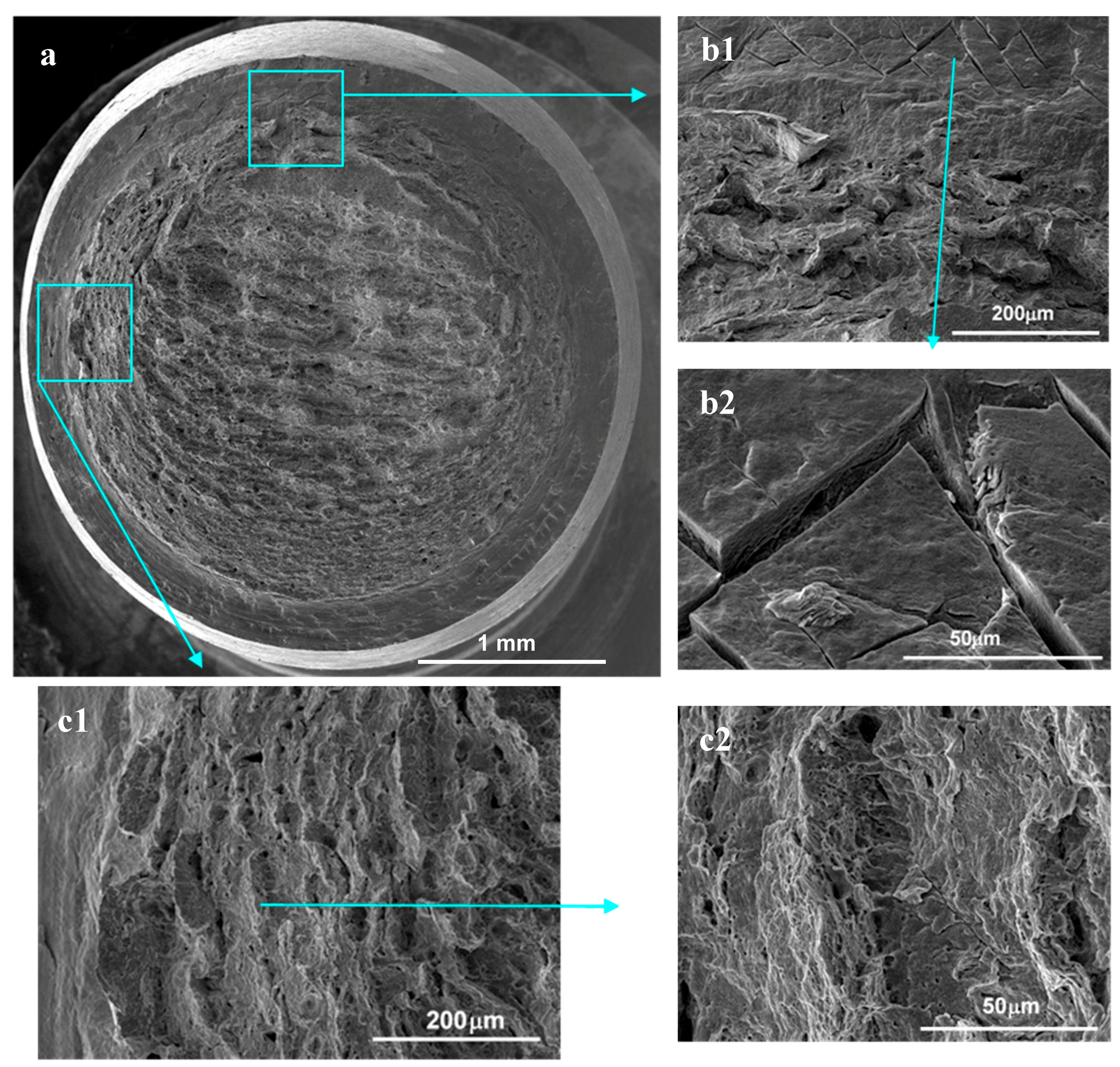
At 450 °C, fracture surfaces were the most similar to fractures in air (Figure 4a). These were ductile to all appearance although slight signs of changes could be found around the original notch root (Figure 4(b1,b2)), such as a stepwise character (Figure 4(c1,c2)) and initiation of surface micro cracks from slip lines (Figure 4(b1)).
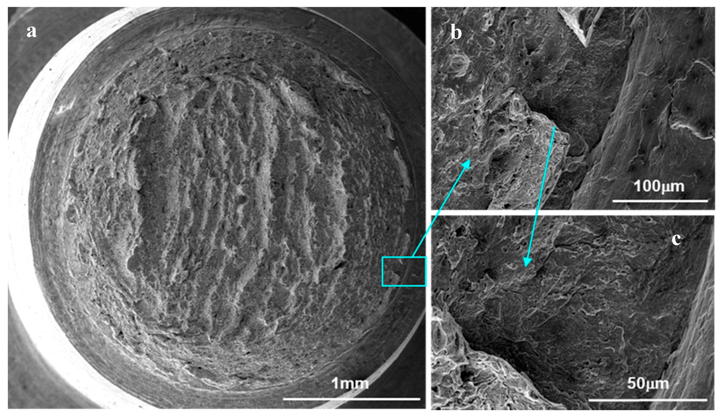
The fracture surface of specimens tested at 400 °C in Pb contained ductile dimples at the center, as in all previous cases (Figure 5a). However, there were many small areas at the position of the original notch root observed (Figure 5b) showing the sharp edge typical of LME fracture surface. The areas close to the edge contained cleavage-like fracture patterns (Figure 5c), typical features for LME.
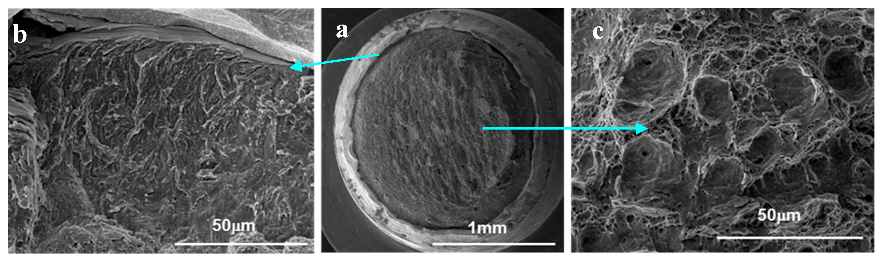
The overall fracture surface of the notched specimens treated with flux and tested in Pb at 350 °C was different than those at higher temperatures. The fracture surface revealed mostly cleavage-like fracture (Figure 6) with several evident crack-initiation sites around the original surface of the notch. Small areas with ductile dimples were observed inside the specimens (Figure 6a). These cleavage-like cracks (Figure 6b,c) were growing during the test, but in different stress-strain conditions, which formed the asymmetrical shape of the largest ductile fracture area. The total area of ductile dimples was distinctively smaller in the specimen B87 loaded at R1 (2 × 10⁻⁶ m/s) (Figure 6a) in comparison to the specimen B88 at R2 (2 × 10⁻⁸ m/s).
The fracture surface of the as received specimen B02 tested at 350 °C (Figure 7a) contained mixed fracture, ductile dimples and shear (Figure 7b) and cleavage-like facets (Figure 7(c1,c2)). The crack-initiation sites around the original surface of the notch were mostly characterized as shear (Figure 7a) and several small areas with cleavage-like fracture and secondary cleavage-like facet (Figure 7d) were also observed.
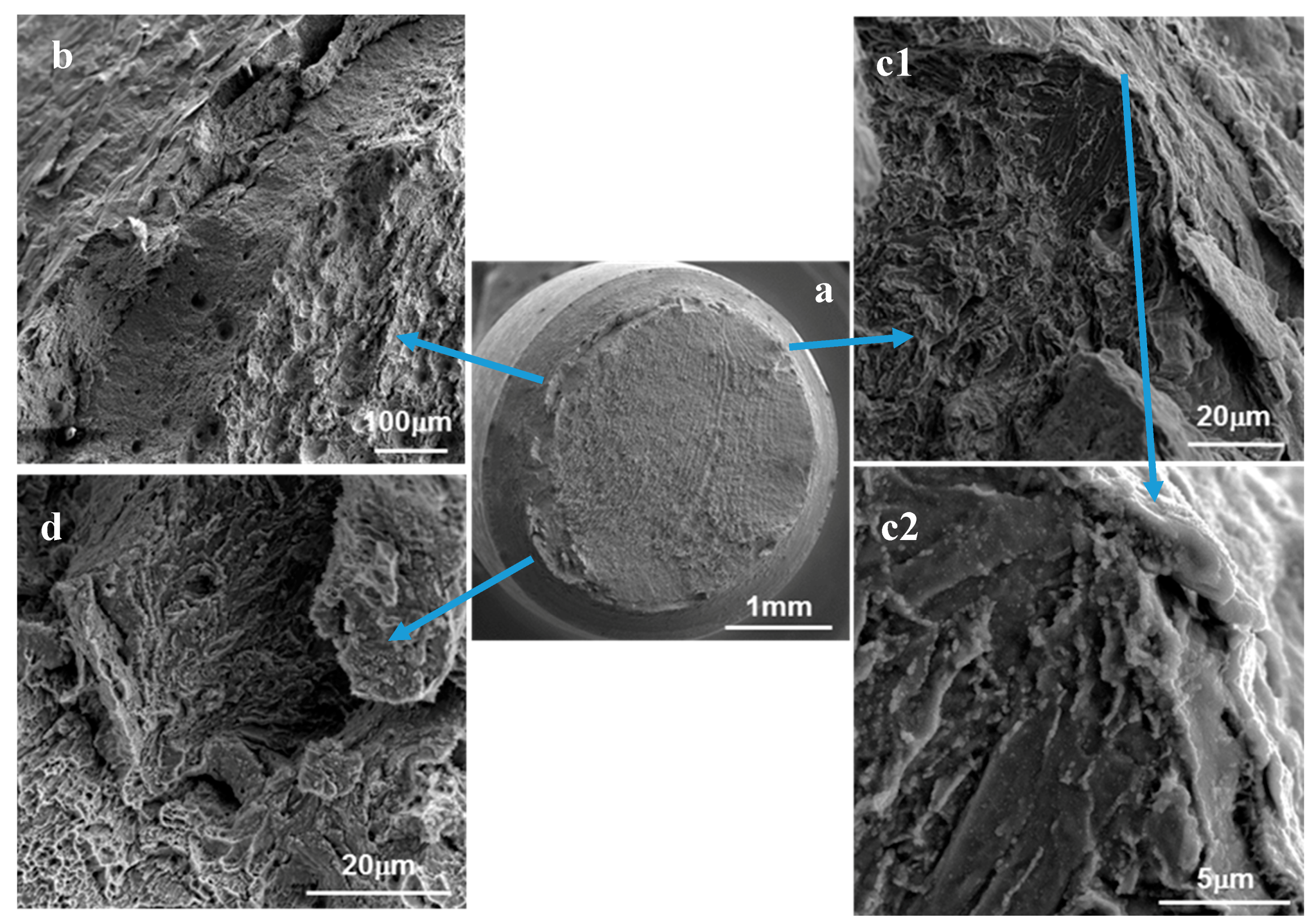
The specimen tested at 300 °C (B90) was originally covered with a layer of solid lead before being loaded in the gas mixture Ar + 6% H2. After testing, on the fracture surface (Figure 8a) ductile dimples were observed (Figure 8c) in the central area and ductile shear fracture at the periphery region. However, cleavage-like fractures also appeared in several places at the edge of the fracture surface (Figure 8b). The size/depth of such cleavage-like facets was estimated to be up to 100 μm. The fracture character was compared to the specimen (B97) with as received surface, which was tested at 300 °C in the same gas, Ar + 6% H2. The fracture of B97 appeared completely ductile.
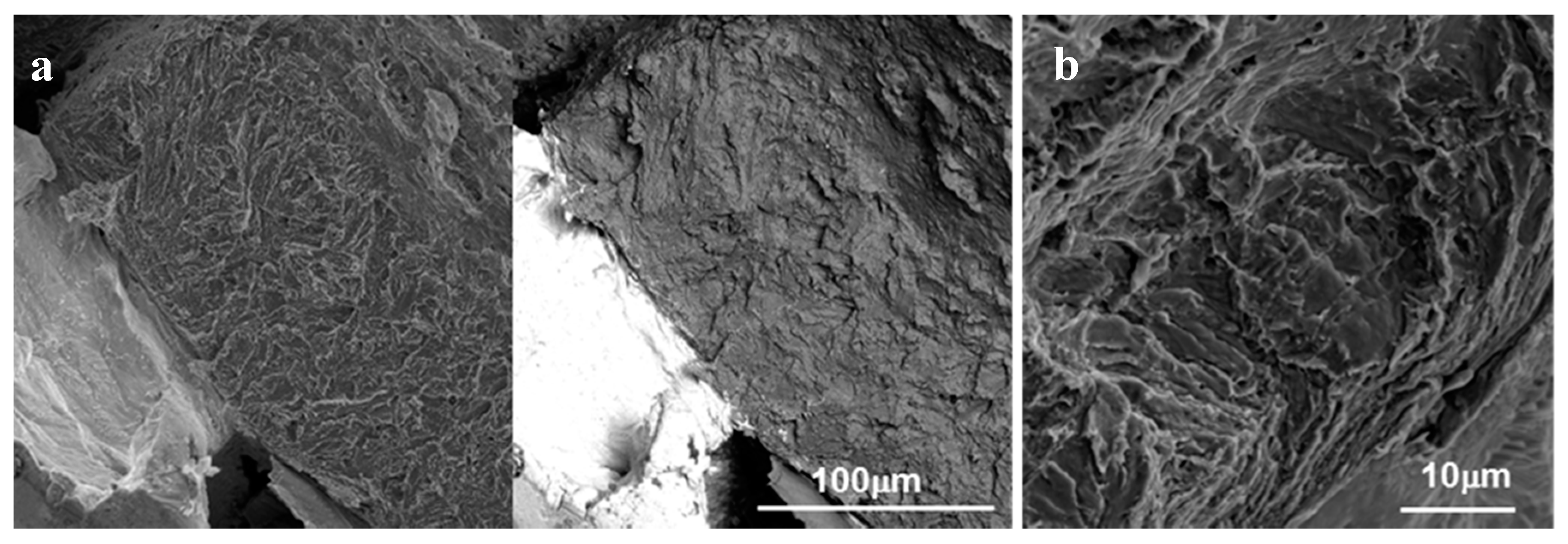
A similar observation was made on the fracture surface of the specimen B07, covered by flux and Pb and tested at R2 (Figure 9). The fracture at the notch root, close to the remains of the solid Pb layer, was cleavage-like in several regions (Figure 9a,b). The dimension of this layer was measured to be up to 100 μm.
This phenomenon is believed to be the Solid Metal Induced Embrittlement [2], which is characterized by the change of fracture mode in the surface area in contact with the solid Pb.
3.3. Cross Section
For several specimens a cross section was produced and observed in the SEM. The interface between the steel and the environment was investigated (by EDS) in order to identify the existence of oxide layers after testing, and thus, their role in the behavior of the material.
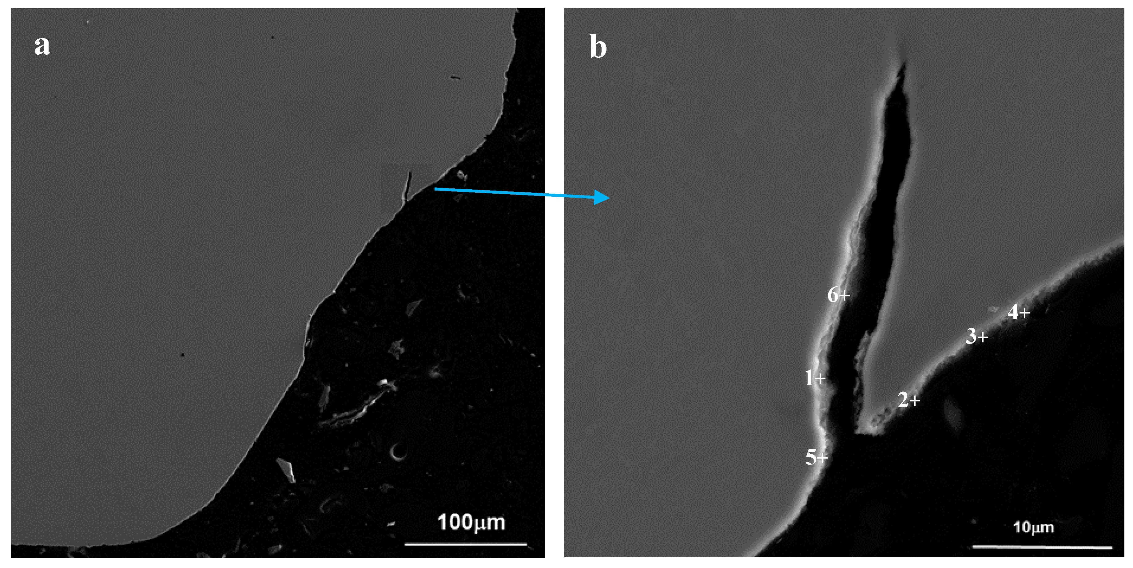
With qualitative line scans analysis, made on the cross-sections of the specimen tested in liquid Pb at 350 °C, it was possible to highlight the presence of oxides at the interface steel/Pb. It was found that the size and the qualitative composition were different in the flux treated and as received surfaces. In case of the specimen B04, originally as received surface, the oxide was about 3 μm thick. In case of the specimen B88, originally flux + Pb treated, the oxide scale was thinner, about 1 μm, and residual Zn was detected. However, the spatial resolution of EDS owing to applied parameters was about 0.7 μm, not enough to evidence trace elements. To confirm the observed traces of Zn from the linescan data, quantitative spot analyses were performed at the interface between the bulk and the remains of the lead environment (Figure 10). The spot analyses measured from 0.1 to 2.6 wt. % of Zn in the position of the original notch surface (Table 6). The probable source of Zn was the flux used to remove the original oxide layer from the steel.
4. Discussion
This paper focuses on giving evidence of LME in the interaction of the ferritic-martensitic steel T91 with liquid Pb in specific experimental conditions. This work was carried out following the previous experience with tests on smooth tensile specimens in liquid Pb at 350–450 °C [7], which did not show any sign of LME. Therefore, the tensile specimens were notched and tested in the same test regime. In these specific conditions, LME cracking was observed.
Nicase et al. [13] reported about the sensitivity of 9Cr ferritic-martensitic steel to embrittlement when in contact with Pb especially in presence of stress concentrators, such as notches. Changes from ductile to transgranular cleavage-like fracture, related to the LME, were observed on these specimen surfaces around the notch root, which is in agreement with the findings of this work.
Temperature. The cleavage-like fracture was observed on the notched specimens loaded to rupture in liquid Pb at 350 °C and 400 °C as well as on the specimens covered by solid lead tested at 300 °C, i.e., below the melting point. On the other hand, no cleavage-like fracture was observed on specimens tested in Pb at 450 °C. This temperature effect is in agreement with other findings where it was stated that LME is more pronounced when approaching the melting/solidification temperature of the liquid metal [2].
Displacement rate. The LME was the most severe and the most evident in tests at 350 °C. Both specimens ruptured prematurely as a result of LME crack initiation and growth.
The specimen B88, loaded at 350 °C, at the slower test rate, R2, exhibited a pop-in (sudden decrease of load) at the maximum load, after plastic deformation. The specimen was loaded over general yielding, therefore, there was a region found at the notch, of about 30 μm, where the initial ductile deformation was visible. This region was followed by the LME cleavage-like crack jump of about 100 μm, which was observed on the fracture surface.
In the specimen B87 (Figure 6) tested at the faster test rate, R1, the LME was more severe and the crack development was slightly different. In fact, the fracture surface is mostly flat and homogeneous; likely there was not a visible crack jump and crack stop. Therefore, it is assumed that the LME crack initiated at maximum load as for the case of B88. However, in this faster loading, the crack did not jump and stopped, but continued to grow during further loading and the measured load decreased gradually down, until the rupture. This observation can be explained by assuming that the applied displacement rate was high enough to keep the material under the notch loaded even if the LME crack grew. From this assumption, it could be deduced that the R1 test rate could be of the same order of magnitude as the LME crack growth rate, i.e., 10−6 m/s. This value was in agreement with values of crack growth rates measured on Compact Tension specimens of the T91 in liquid Pb–Bi that showed LME at 300 °C [14].
At 350 and 400 °C and the applied displacement rates, 1 and 100 × 10−6 m/s, T91 showed negative strain rate sensitivity, i.e., load increased with decreasing displacement rate. This fact was an indication of Dynamic strain ageing processes, which used to be observed in parallel to Environmentally Assisted Cracking in high temperature water [15].
Wetting. At 350 °C, the effect of surface flux application was studied. As can be seen from results, LME was observed at both flux + Pb treated and as received specimens. Moreover, the load-displacement curves (Figure 3c) showed that the flux + Pb treated specimens reached lower rupture displacement than the as received ones and the air tests. This observation meant that the LME crack initiation on the flux + Pb treated surface was facilitated, compared to the case of the as received.
Knowing that wetting by liquid metal, i.e., direct contact of the metals without any interlayer, is the pre-condition for the LME occurrence [3], some local wetting had to be assumed on the surface of test specimens before LME crack initiation. However, from the cross section observations and EDS analyses followed that both specimen surfaces, the flux treated and the as received, were covered by about 1–3 μm thin oxide layers. In the case of the flux + Pb treated specimen, it was not clear whether the specimen surface stayed wetted or not before the onset of the cracking. This could not be established because the behavior of the Pb layer (solidified on the surface) during the test cell heating up and then loading was unknown. In previous tests with smooth specimens [7], where the T91 surface wetting was stimulated by the same flux + Pb treatment, a similar thin oxide layer appeared on the specimen after the tensile test, but no LME crack was initiated. It is likely that the deposited Pb layer melted in the surrounding liquid lead and that a new thin oxide layer formed at the specimen surface from the small amount of oxygen dissolved in the lead. However, this obviously had a different role in smooth and notched specimens.
To explain the apparent contradiction, it was considered that the newly developed thin oxide had to be broken by the high local strain-stress conditions before the LME crack initiation. At the same time, the oxide layer built up on flux + Pb treated surfaces was much thinner and less protective during the deformation than the oxide on the specimens without flux treatment. The behavior of the oxide might likely be affected by remaining traces of flux, for example by the presence of Zn, which was detected on the surface (Figure 10). However, by means of an older SEM, the impurity traces were not measured on the smooth tensile specimens as referred in a previous paper [7]. On the other hand, if there was the presence of Zn impurities on the surface, this did not stimulate LME crack initiation in smooth tensile specimens in liquid Pb [7]. Moreover, this was proven by SSRT tests with only flux treated specimens in air and Pb, where no cracking occurred. Therefore, the presence of Zn was not affecting the cracking behavior of the material.
Solid metal induced embrittlement (SMIE). The analysis of the fracture surfaces at the SEM also revealed several areas of cleavage-like fracture for the notched specimens B90 and B07, which were treated with the flux and covered with the thin layer of Pb prior to tensile test. The test itself was then performed at 300 °C (which meant that the Pb stayed solid) in the mixture of Ar–H2. The solid Pb layer formed something like a collar around the specimens that during deformation detached itself from the surface of the steel. This gave evidence that it was not likely that the applied deformation energy transformed into the heat during loading could heat the specimen locally above the melting point of Pb (327 °C) and therefore melting the Pb could affect the steel. It would be more probable that instead of LME, as in the previous cases at 350 °C and 400 °C, the specimen underwent Solid Metal Induced Embrittlement. According to [2], the same processes causing LME could also cause SMIE if the temperature is under the melting point of the embrittling metal. Fracture surfaces created during LME and SMIE both contained cleavage-like fractures with the same appearance. The area of cleavage-like fracture of the specimen B90 was observed only in the distance about 50 μm from the original surface of the notch then the fracture mode continuously changed to ductile shear. This is in agreement with the finding that the SMIE is typically much less severe than the LME [2]. Likewise, the specimen B90 could be affected by hydrogen embrittlement from the hydrogen gas penetrating the solid layer could be excluded, too. The other notched specimen, B97, which was tested under the same conditions as above but without any Pb and only in the gas Ar + H2, fractured by fully ductile manner. It would be beneficial to perform more tests with the solid Pb, at even lower temperatures than the presented one, to discover at which temperature the Pb would still cause SMIE and therefore could affect the cracking behavior of the structural steel.
All these findings showed that the conditions formed under the notch, i.e., multi-axial stress state, stress concentration, and high local plastic strain, (conditions close to the onset of ductile voids creation) could induce LME in the T91 in contact with liquid Pb. These were highlighted for both LME and SMIE.
5. Conclusions
The susceptibility of T91 steel to cracking in liquid Pb was investigated using slow strain rate tests of notched specimens. Several specimens were surface treated with flux and a layer of Pb was deposited on their surface. The notched specimens tested in liquid Pb at 350 °C and 400 °C underwent Liquid Metal Embrittlement, LME. The LME severity was the highest at 350 °C and decreased with increasing temperature; no LME occurred at 450 °C.
At 350 °C, a significant and extensive change of the fracture mode to cleavage-like for both applied displacement rates (2 × 10⁻⁸ m/s and 2 × 10⁻⁶ m/s) was observed indicating LME crack initiation and growth under loading. The LME crack growth rate of T91 in liquid lead was estimated to be in the order of 10−6 m/s at 350 °C.
At 400 °C, LME was also observed for both applied displacement rates, but only in localized areas close to the notch root indicating only crack initiation without or very slow growth.
The cleavage-like fracture areas were observed also for the specimens pre-covered with solid Pb and tested at 300 °C in Ar + H2 gas. The cleavage-like areas reached up to a depth of about 100 μm from the notch root surface, probably showing the presence of the Solid Metal Induced Embrittlement (SMIE).
In the T91 in contact with the Pb, both LME and SMIE were induced owing to the multi-axial stress field and the high local plastic strain, the condition was close to the onset of ductile void creation. The wetting, precondition of LME above the melting point, was reached after a thin oxide layer was broken under the high stress-strain.
Acknowledgments
This work was supported by the project GAČR-KAMILE c.n. 16-15008S. Moreover, the presented work was financially supported by the Ministry of Education, Youth and Sport Czech Republic — project LQ1603 Research for SUSEN. This work has been realized within the SUSEN Project (established in the framework of the European Regional Development Fund (ERDF) in project CZ.1.05/2.1.00/03.0108 and of the European Strategy Forum on Research Infrastructures (ESFRI) in the project CZ.02.1.01/0.0/0.0/15_008/0000293, which is financially supported by the Ministry of Education, Youth and Sports — project LM2015093 Infrastructure SUSEN.
Author Contributions
Michal Chocholousek and Jakub Klecka carried out the experiments. Anna Hojná conceived and designed the experiments, did the fracture surface study and the EDS analyses, and wrote the paper. Fosca Di Gabriele contributed to the experimental part, analyzed the data, and wrote the paper.
Conflicts of Interest
The authors declare no conflict of interest. The founding sponsors had no role in the design of the study, in the collection, analyses, or interpretation of data; in the writing of the manuscript, and in the decision to publish the results.
References
- Lynch, S.P. Metal-Induced Embrittlement of Materials. Mater. Charact. 1992, 28, 279–289. [Google Scholar] [CrossRef]
- Lynch, S.P. Chapter 2: Hydrogen embrittlement (HE) phenomena and mechanisms; Chapter 18: Failures of structures and components by metal-induced embrittlement. In Stress Corrosion Cracking: Theory and Practice; Raja, V.S., Shoji, T., Eds.; Woodhead Publishing Limited: Cambridge, UK, 2011; Volume 1, pp. 90–130, 714–748, eBook ISBN:9780857093769, Hardcover ISBN:9781845696733. [Google Scholar]
- Auger, T.; Lorang, G.; Guérin, S.; Pastol, J.-L.; Gorse, D. Effect of contact conditions on embrittlement of T91 steel by lead-bismuth. J. Nucl. Mater. 2004, 335, 227–231. [Google Scholar] [CrossRef]
- Weisenburger, A.; Schroer, C.; Jianu, A.; Heinzel, A.; Konys, J.; Steiner, H.; Mueller, G.; Fazio, C.; Gessi, A.; Babayan, S.; et al. Long term corrosion on T91 and AISI1 316L steel in flowing lead alloy and corrosion protection barrier development: Experiments and models. J. Nucl. Mater. 2011, 415, 260–269. [Google Scholar] [CrossRef]
- Schroer, C.; Wedemeyer, O.; Skrypnik, A.; Novotny, J.; Konys, J. Corrosion kinetics of Steel T91 in flowing oxygen-containing lead-bismuth eutectic at 450 °C. J. Nucl. Mater. 2012, 431, 105–112. [Google Scholar] [CrossRef]
- Muller, G.; Heinzel, A.; Konys, J.; Schumacher, G.; Weisenburger, A.; Zimmermann, F.; Engelko, V.; Rusanov, A.; Markov, V. Behavior of steels in flowing liquid PbBi eutectic alloy at 420–600 °C after 4000–7200 h. J. Nucl. Mater. 2004, 335, 163–168. [Google Scholar] [CrossRef]
- Hojna, A.; Di Gabriele, F.; Klecka, J.; Burda, J. Behaviour of the steel T91 under uniaxial and multiaxial slow loading in contact with liquid lead. J. Nucl. Mater. 2015, 466, 292–301. [Google Scholar] [CrossRef]
- Alves, M.; Jones, N. Influence of hydrostatic stress on failure of axisymmetric notched specimens. J. Mech. Phys. Solids 1999, 47, 647–667. [Google Scholar] [CrossRef]
- Alves, M.; Jones, N. Failure site of axisymmetric notched specimens as predicted by continuum damage mechanics. In Damage & Fracture Mechanics VI, 1st ed.; Selvadurai, A.P.S., Brebbia, C.A., Eds.; WIT Press: Southampton, UK, 2000; pp. 139–147. ISBN 1-85312-812-0. [Google Scholar]
- Mirone, G.; Corallo, D. A local viewpoint for evaluating the influence of stress triaxiality and Lode angle on ductile failure and hardening. Int. J. Plast. 2010, 26, 348–371. [Google Scholar] [CrossRef]
- Van den Bosch, J. ADS Candidate Materials Compatibility with Liquid Metals in a Neutron Irradiation Environment. Ph.D. Thesis, University of Gent, Gent, Belgium, June 2009. [Google Scholar]
- Savruk, M.P.; Kazberuk, A. Rectangular Specimens with Edge Notches. In Stress Concentration at Notches, 1st ed.; Springer International Publishing: Basel, Switzerland, 2017; pp. 279–322. ISBN 978-3-319-44555-7. [Google Scholar]
- Nicaise, G.; Legris, A.; Vogt, J.B.; Foct, J. Embrittlement of the martensitic steel 91 tested in liquid lead. J. Nucl. Mater. 2001, 296, 256–264. [Google Scholar] [CrossRef]
- Hojna, A.; Di Gabriele, F. On the kinetics of LME for the ferritic martensitic steel T91 immersed in liquid PbBi eutectic. J. Nucl. Mater. 2011, 413, 21–29. [Google Scholar] [CrossRef]
- Seifert, H.P.; Ritter, S.; Hickling, J. Environmentally-assisted cracking of low alloy RPV and piping steels under LWR conditions. In Proceedings of the 11th International Conference on Environmental Degradation of Materials in Nuclear Power Systems—Water Reactors, Stevenson, WA, USA, 10–14 August 2003. NACE/TMS/ANS, Paper No. 47. [Google Scholar]
Figure 1.
Light Microscope image of the microstructure of the T91 steel in the as-received state showing grain boundaries, bundles of martensite laths, and a few large carbide particles.
Figure 1.
Light Microscope image of the microstructure of the T91 steel in the as-received state showing grain boundaries, bundles of martensite laths, and a few large carbide particles.
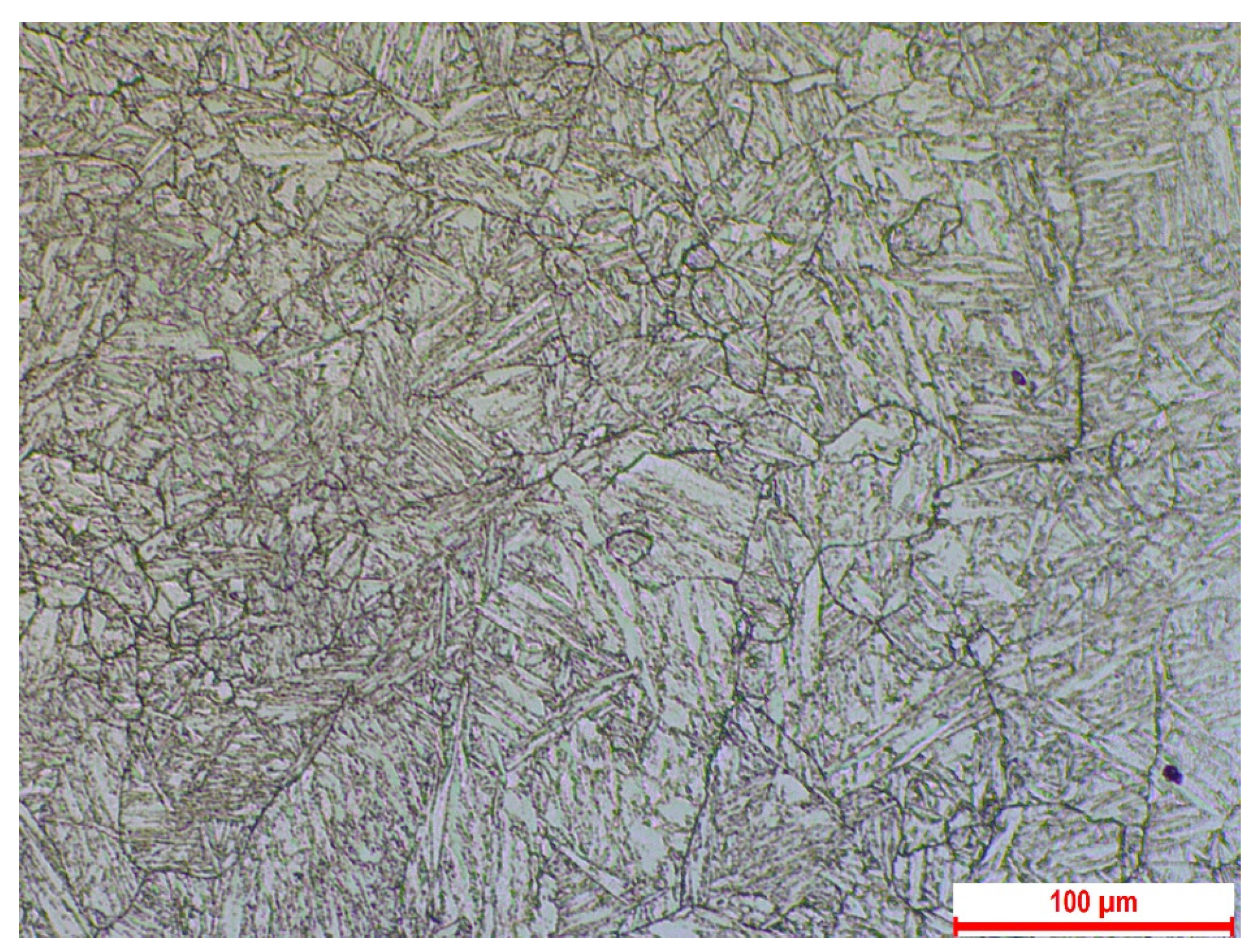
Figure 2.
Image of the specimen (a) The notched tensile specimen before test and (b) the notch profile (in mm).
Figure 2.
Image of the specimen (a) The notched tensile specimen before test and (b) the notch profile (in mm).
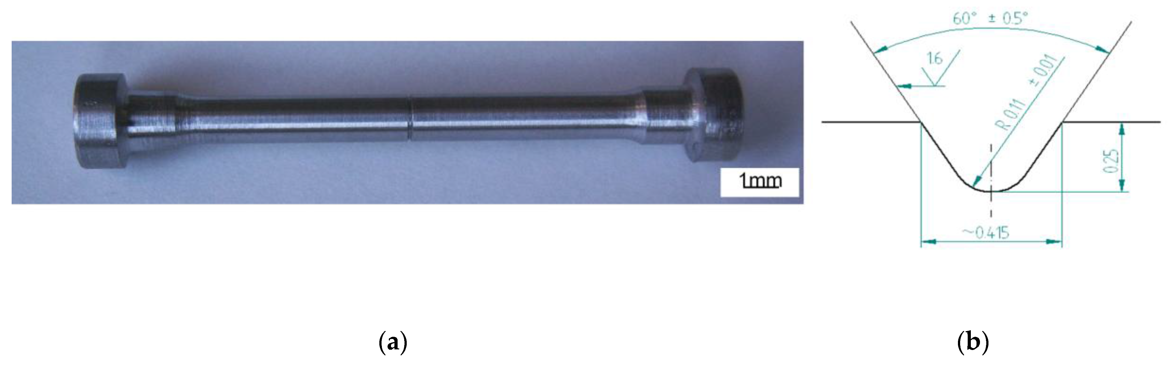
Figure 3.
Load-displacement curves of notched specimens tested at (a) 450 °C, (b) 400 °C, (c) 350 °C, and (d) 300 °C in air or Ar + 6% H2 and in liquid Pb applying test rates R1 (2 × 10⁻⁶ m/s) and R2 (2 × 10⁻⁸ m/s). Surface of specimens was as received (as rec.) or treated by flux and lead (flux + Pb). The star next to the specimen name means shorter notch depth, 0.15 mm, which consequently caused higher load.
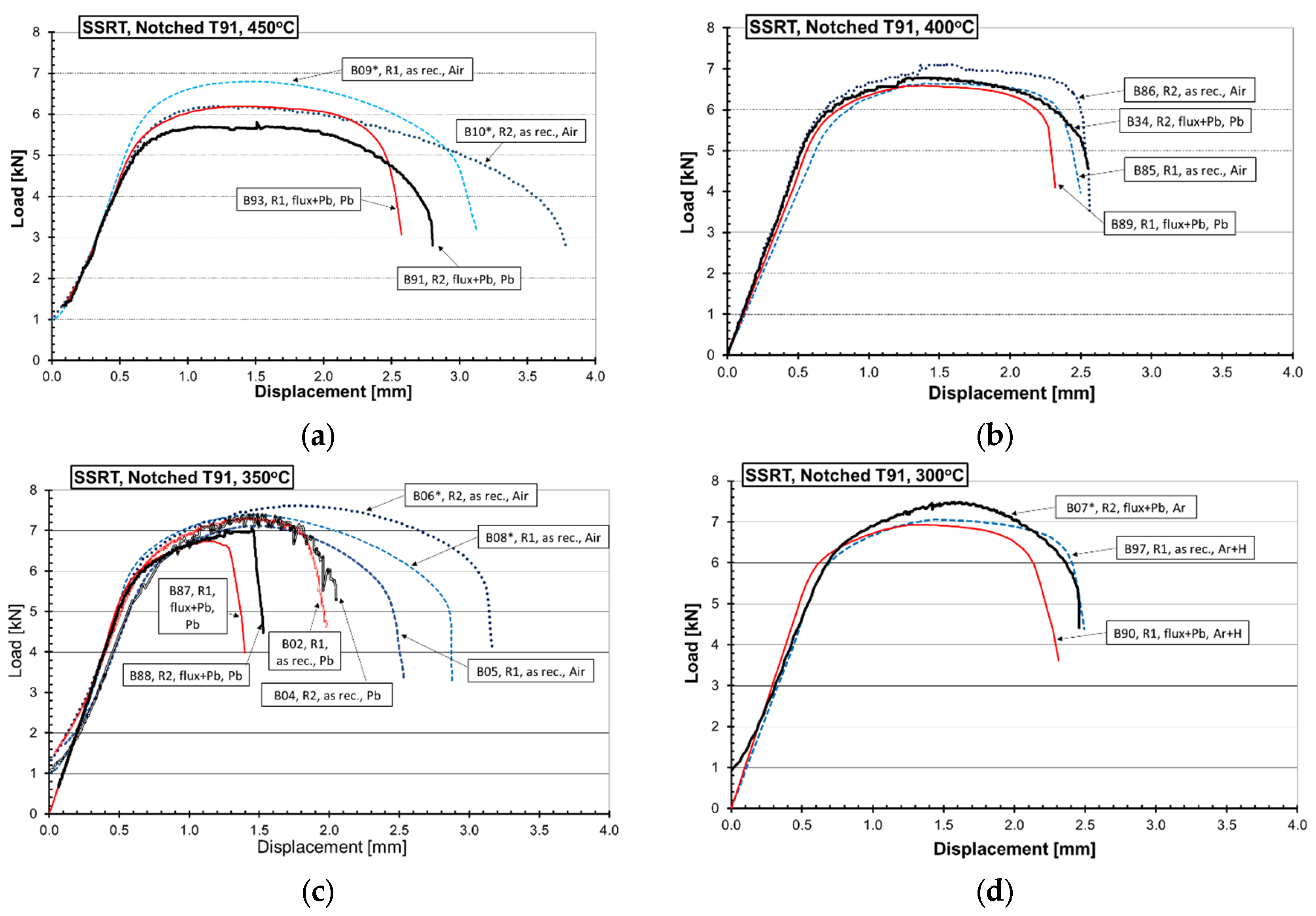
Figure 4.
Fracture surface of the notched specimen (B93) tested in lead at 450 °C, R1 (2 × 10⁻⁶ m/s): (a) General view; (b1) crack initiation from the notch root with (b2) detail of micro cracks initiated on slip lines; (c1) another crack-initiation site with (c2) detail of characteristic shear patterns.

Figure 5.
Fracture surface of the specimen (B89) tested in lead at 400 °C, R1 (2 × 10⁻⁶ m/s). (a) General view, (b) LME crack initiation at many points around the notch, (c) detail of the cleavage-like fracture at the edge.
Figure 5.
Fracture surface of the specimen (B89) tested in lead at 400 °C, R1 (2 × 10⁻⁶ m/s). (a) General view, (b) LME crack initiation at many points around the notch, (c) detail of the cleavage-like fracture at the edge.

Figure 6.
(a) Fracture surface of the notched specimen (B87) tested in liquid lead at 350 °C, R1 (2 × 10⁻⁶ m/s); a small area of ductile fracture stayed in the central area, (b) selected detail of crack-initiation site showing (c) characteristic cleavage-like patterns.
Figure 6.
(a) Fracture surface of the notched specimen (B87) tested in liquid lead at 350 °C, R1 (2 × 10⁻⁶ m/s); a small area of ductile fracture stayed in the central area, (b) selected detail of crack-initiation site showing (c) characteristic cleavage-like patterns.
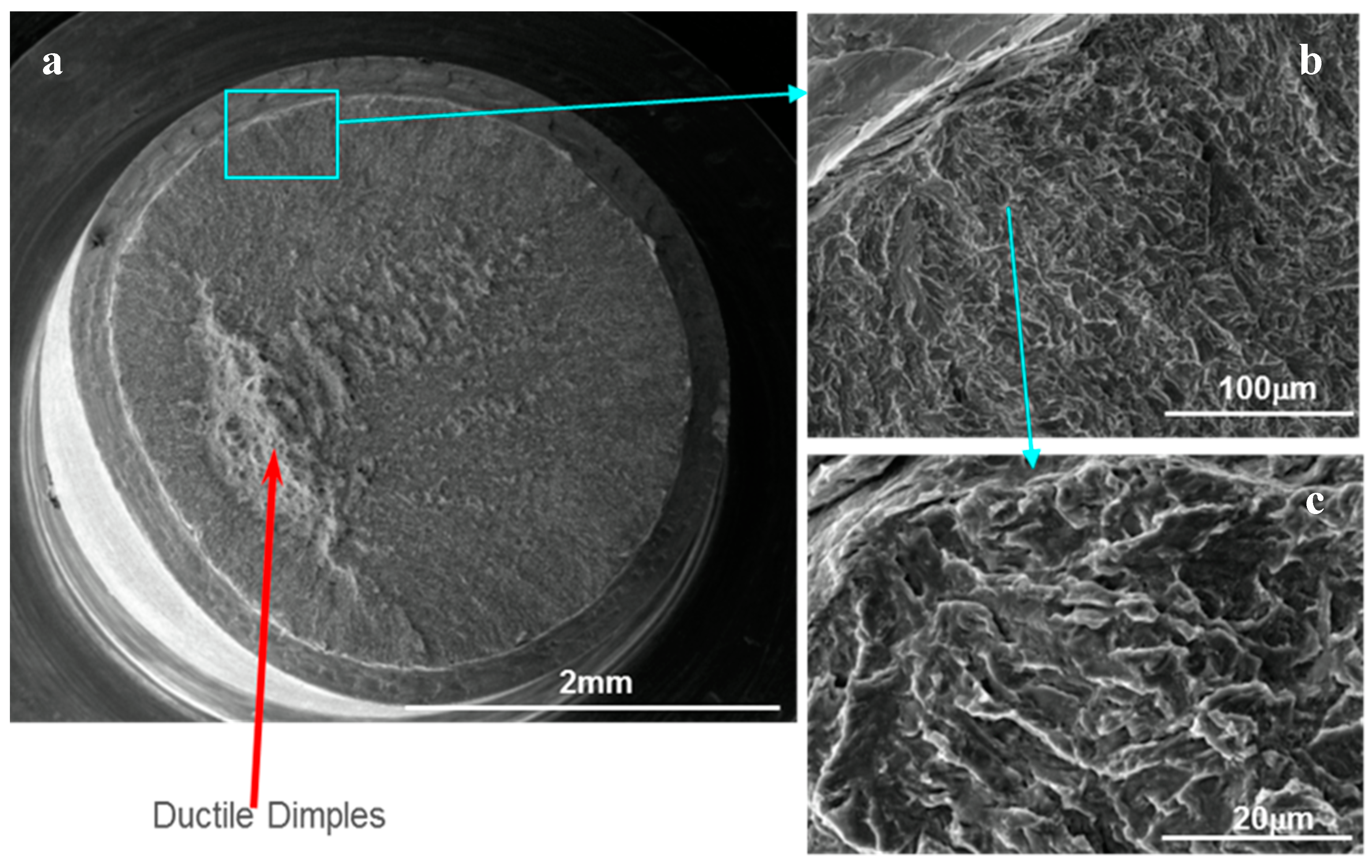
Figure 7.
Fracture surface of the notched specimen (B02) with as received surface, tested in Pb at 350 °C, R1 (2 × 10⁻⁶ m/s); (a) general view, (b) twin shear cracks connecting the ductile fracture in the centre and the notch root, (c1) cleavage-like facet of LME crack initiating from the notch and (c2) its detail, (d) secondary cleavage-like facet of LME initiating from the shear crack tip.

Figure 8.
Fracture surface of the notched specimen (B90), originally covered by flux and Pb layer, tested in Ar + 6% H2 gas at 300 °C and R1 (2 × 10⁻⁶ m/s); (a) general view showing the whole solid lead around the specimen; (b) details of the cleavage-like facets of SMIE crack initiating from the notch; and (c) ductile dimpled fracture in the center.

Figure 9.
Details of Solid Metal Induced Embrittlement (SMIE) crack surrounding the fracture surface of the notched specimen (B07), originally covered by the flux and Pb layer, tested in a cell under Ar gas at 300 °C, R2 (2 × 10⁻⁸ m/s). (a) SE and BSE images of large SMIE cleavage-like crack initiating from the notch surface pre-covered by Pb; (b) Detail of short SMIE cleavage-like crack surrounded by ductile deformation.

Figure 10.
Cross sections specimen tested in Pb at 350 °C at R2 (2 × 10⁻⁸ m/s) showing the interface between the steel and the environment at the (a) notch originally covered by flux and Pb layer. In (b) detail of a crack with the point analyses reported in Table 6.
Figure 10.
Cross sections specimen tested in Pb at 350 °C at R2 (2 × 10⁻⁸ m/s) showing the interface between the steel and the environment at the (a) notch originally covered by flux and Pb layer. In (b) detail of a crack with the point analyses reported in Table 6.


Table 1.
Composition of the steel T91 as provided by the producer in wt. %.
| Fe | C | Cr | Mo | Mn | Si | Ni | V | Cu | Nb | P | Al | Ti | S | N |
|---|---|---|---|---|---|---|---|---|---|---|---|---|---|---|
| Bal. | 0.102 | 8.895 | 0.889 | 0.401 | 0.235 | 0.121 | 0.202 | 0.080 | 0.079 | 0.019 | 0.010 | 0.004 | 0.0007 | 0.048 |
Table 2.
Mechanical properties of the test material determined in standard tensile tests of 10−4 s−1.
Table 2.
Mechanical properties of the test material determined in standard tensile tests of 10−4 s−1.
| T (°C) | Rp0.2 (MPa) | Rm (MPa) | Am (%) | A (%) | Z (%) |
|---|---|---|---|---|---|
| 300 | 503 | 621 | 9.4 | 20 | 75 |
| 350 | 459 | 557 | 7.8 | 18 | 73 |
| 500 | 464 | 498 | 4.2 | 19 | 85 |
Rp0.2 is the yield strength, Rm is the ultimate tensile strength, Am is the elongation at Rm, A is the total elongation, and Z is the reduction of area.
Table 3.
Chemical composition of the flux.
| Compound | SnCl2 | NH4Cl | HCl | NaF | ZnCl2 | H2O |
|---|---|---|---|---|---|---|
| Wt. % | 3.7 | 13.2 | 4.2 | 0.8 | 65.5 | 12.6 |
Table 4.
Test matrix.
| T (°C) | Specimen | Surface Treatment | Cell Environment | Displacement Rate (m/s) |
|---|---|---|---|---|
| 300 | B97 | as received | Ar + 6% H2 | R1 (2 × 10⁻⁶) |
| B90 | flux + Pb | Ar + 6% H2 | R1 | |
| B07 * | flux + Pb | Argon | R2 (2 × 10⁻⁸) | |
| 350 | B05, B08 *, B92 | as received | Air | R1 |
| B01, B06 * | as received | Air | R2 | |
| B02, B03 | as received | Pb | R1 | |
| B04 | as received | Pb | R2 | |
| B87 | flux + Pb | Pb | R1 | |
| B88 | flux + Pb | Pb | R2 | |
| 400 | B85 | as received | Air | R1 |
| B86 | as received | Air | R2 | |
| B89 | flux + Pb | Pb | R1 | |
| B33, B34 | flux + Pb | Pb | R2 | |
| 450 | B09 * | as received | Air | R1 |
| B10 * | as received | Air | R2 | |
| B93 | flux + Pb | Pb | R1 | |
| B91 | flux + Pb | Pb | R2 |
* notch depth = 0.15 mm.
Table 5.
Test results: Fgy and Fmax are loads at general yielding and maximum; f_max and f_final are displacements at maximum load and rupture. LME max is the maximum cleavage-like crack depth at rupture from SEM observations.
Table 5.
Test results: Fgy and Fmax are loads at general yielding and maximum; f_max and f_final are displacements at maximum load and rupture. LME max is the maximum cleavage-like crack depth at rupture from SEM observations.
| Spec. | T (°C) | Surface Treatment | Cell Environment | Displ. Rate (m/s) | Fgy (kN) | Fmax (kN) | f_max (mm) | f_final (mm) | LME Max (mm) |
|---|---|---|---|---|---|---|---|---|---|
| B97 | 300 | as rec. | Ar + 6% H2 | R1 (2 × 10⁻⁶) | 5.90 | 7.06 | 1.44 | 2.49 | n.a. |
| B90 | flux + Pb | Ar + 6% H2 | R1 | 5.76 | 6.94 | 1.33 | 2.31 | 0.05 | |
| B07 * | flux + Pb | Argon | R2 (2 × 10⁻⁸) | 5.89 | 7.49 | 1.57 | 2.47 | 0.11 | |
| B92 | 350 | as rec. | Air | R1 | 5.59 | 6.81 | 1.40 | 2.39 | n.a. |
| B05 | as rec. | Air | R1 | 5.67 | 7.12 | 1.54 | 2.53 | n.a. | |
| B08 * | as rec. | Air | R1 | 6.29 | 7.38 | 1.46 | 3.25 | n.a. | |
| B06 * | as rec. | Air | R2 | 6.12 | 7.62 | 1.84 | 4.10 | n.a. | |
| B02 | as rec. | Lead | R1 | 5.51 | 7.32 | 1.39 | 2.12 | 0.10 | |
| B03 | as rec. | Lead | R1 | 5.98 | 7.28 | 1.38 | 2.34 | 0.20 | |
| B04 | as rec. | Lead | R2 | 5.26 | 7.42 | 1.45 | 2.05 | 0.40 | |
| B87 | flux + Pb | Lead | R1 | 5.43 | 6.73 | 1.10 | 1.40 | 0.55 | |
| B88 | flux + Pb | Lead | R2 | 5.46 | 7.07 | 1.45 | 1.98 | 0.60 | |
| B85 | 400 | as rec. | Air | R1 | 5.34 | 6.64 | 1.39 | 2.50 | n.a. |
| B89 | flux + Pb | Lead | R1 | 5.41 | 6.59 | 1.38 | 2.32 | 0.10 | |
| B86 | as rec. | Air | R2 | 5.23 | 6.71 | 1.48 | 2.57 | n.a. | |
| B33 | flux + Pb | Lead | R2 | 5.43 | 6.68 | 1.25 | 2.24 | 0.44 | |
| B34 | flux + Pb | Lead | R2 | 5.36 | 6.78 | 1.38 | 2.55 | 0.46 | |
| B09 * | 450 | as rec. | Air | R1 | 5.30 | 6.80 | 1.47 | 3.17 | n.a. |
| B10 * | as rec. | Air | R2 | 5.29 | 6.16 | 1.22 | 3.77 | n.a. | |
| B94 | as rec. | Air | R2 | 5.25 | 6.38 | 1.25 | 2.73 | n.a. | |
| B93 | flux + Pb | Lead | R1 | 5.29 | 6.19 | 1.40 | 2.59 | 0 | |
| B91 | flux + Pb | Lead | R2 | 4.91 | 5.81 | 1.55 | 2.84 | 0 |
* notch depth = 0.15 mm.
Table 6.
Spot analyses (positioned in Figure 10b), wt. %.
Table 6.
Spot analyses (positioned in Figure 10b), wt. %.
| Points/Elements | O | Fe | Cr | Si | Zn | Pb |
|---|---|---|---|---|---|---|
| 1 | 18.81 | 67.83 | 11.31 | 0.48 | 0.76 | 0.42 |
| 2 | 2.76 | 86.55 | 9.64 | 0.83 | 0.22 | |
| 3 | 3.6 | 86.55 | 9.4 | 1.33 | 0.32 | |
| 4 | 5.25 | 84.26 | 9.06 | 1.12 | 0.32 | |
| 5 | 6.01 | 78.18 | 12.54 | 2.64 | 0.64 | |
| 6 | 4.85 | 80.1 | 12.4 | 1.86 | 0.79 |
© 2017 by the authors. Licensee MDPI, Basel, Switzerland. This article is an open access article distributed under the terms and conditions of the Creative Commons Attribution (CC BY) license (http://creativecommons.org/licenses/by/4.0/).
Share and Cite
MDPI and ACS Style
Di Gabriele, F.; Hojna, A.; Chocholousek, M.; Klecka, J. Behavior of the Steel T91 under Multi Axial Loading in Contact with Liquid and Solid Pb. Metals 2017, 7, 342. https://doi.org/10.3390/met7090342
AMA Style
Di Gabriele F, Hojna A, Chocholousek M, Klecka J. Behavior of the Steel T91 under Multi Axial Loading in Contact with Liquid and Solid Pb. Metals. 2017; 7(9):342. https://doi.org/10.3390/met7090342
Chicago/Turabian StyleDi Gabriele, Fosca, Anna Hojna, Michal Chocholousek, and Jakub Klecka. 2017. "Behavior of the Steel T91 under Multi Axial Loading in Contact with Liquid and Solid Pb" Metals 7, no. 9: 342. https://doi.org/10.3390/met7090342
Note that from the first issue of 2016, this journal uses article numbers instead of page numbers. See further details here.