In Situ Study of Phase Transformations during Non-Isothermal Tempering of Bainitic and Martensitic Microstructures

1
Département de Génie Mécanique, École de Technologie Supériere, Montréal, QC H3C 1K3, Canada
2
Finkl Steel Inc., 100 McCarthy, Saint-Joseph-de-Sorel, QC J3R 3M8, Canada
*
Authors to whom correspondence should be addressed.
Metals 2017, 7(9), 346; https://doi.org/10.3390/met7090346
Submission received: 30 July 2017
/
Revised: 31 August 2017
/
Accepted: 1 September 2017
/
Published: 4 September 2017
(This article belongs to the Special Issue Bainite and Martensite: Developments and Challenges)
Abstract
:Phase transformations during non-isothermal tempering of bainitic or martensitic microstructures obtained after quenching of a medium-carbon low-alloy steel was studied. The microstructures correspond to different locations of an as-quenched large-sized forged ingot used as a die material in the automotive industry. High-resolution dilatometry experiments were conducted to simulate the heat treatment process, as well as to investigate different phenomena occurring during non-isothermal tempering. The microstructures were characterized using optical and scanning electron microscopy. Dilatometry analyses demonstrated that tempering behavior varied significantly from bainitic to martensitic microstructures. Retained austenite, which exists between bainitic ferrite sheaves, decomposes to lower bainite causing a remarkable volume increase. It was found that this decomposition finishes below 386 °C. By contrast, martensite tempering was accompanied with a volume decrease due to the decomposition of medium-carbon martensite to low carbon martensite and carbides.

1. Introduction
Automotive industries’ high demands for large size plastic components, such as bumpers and dashboards, have resulted in the production of ever larger-sized die steels. Consistent and uniform mechanical properties throughout the volume of the die material are required by industry [1]. The die materials are generally made of medium-carbon low-alloy steels and their manufacturing process consists of ingot casting, open die forging, quenching, tempering, and final machining [1,2]. The heat treatment usually includes austenitizing in the 840–880 °C temperature range, quenching and double-tempering between 550 °C and 600 °C.
The as-quenched microstructure is comprised of bainite, martensite, plus some retained austenite [3,4,5]. The transformation of austenite to bainite and martensite during quenching is dependent on the cooling rate, chemical composition of the steel and prior austenite grain size and can be predicted by continuous cooling transformation (CCT) diagrams [3,6,7]. The as-quenched microstructure will then rely on the mutual influences of the above factors. However, due to the large size of the forged block, significant temperature variations are generated between the surface and the center during quenching. Therefore, as it is difficult to improve the quenched microstructure, the material properties are optimized by modification of tempering parameters [8]. Hence, systematic study of phase transformations and microstructure evolution of the die steel during non-isothermal tempering is highly desired.
Phase transformation during non-isothermal tempering with a constant heating rate can be divided into the following stages:
Stage 1 (occurring below 80 °C): The stress fields of dislocations, lattice defects, and cell walls in the martensite, particularly interstitial lattice sites close to these defects provide lower energy sites for carbon. Stage 1 of tempering consists of segregation of carbon atoms to these lower energy sites and pre-precipitation clustering in the iron matrix [4,9,10,11,12,13].
Stage 2 (100–200 °C): In steels containing more than 0.2 wt % C, at temperatures between 100 °C and 200 °C, ε-carbide is the first carbide precipitating in the matrix. Some authors also reported η-carbide formation in low carbon steel at this temperature range [11,14,15].
Stage 3 (200–350 °C): Retained austenite, if present, decomposes at tempering temperatures of 200 °C to 350 °C. The behavior of retained austenite during tempering significantly varies as a function of steel composition. It generally consists of transformation into ferrite and cementite (Fe3C) [4,9,12,16]. However, transformation into lower bainite has been reported by Yan et al. [8]. Additionally, Podder and Bhadeshia’s investigations on retained austenite in bainitic steels revealed that retained austenite transformed into martensite in the cooling process after tempering [17].
Stage 4 (250–450 °C): This stage commonly referred to as the final stage of tempering consists in the transformation of the metastable ε-carbide to cementite in the temperature range of 250 °C to 450 °C. The preliminary morphology of cementite is needle-like which nucleates from martensite lath boundaries or ferrite grain boundaries. This phase transformation causes a remarkable length decrease and can be clearly detected during the dilatometry test [4,9,12,18].
It is worth mentioning that the above temperature ranges are approximate values and can differ depending on steel composition, microstructure and heating rate [4,9,10,11,12]. Time temperature transformation diagrams (TTT) are also used to determine the phase transformation of quenching and tempering process in non-equilibrium conditions but they are not capable to predict different stages during non-isothermal tempering either retained austenite decomposition. Despite many research studies dealing with martensitic phase transformation during tempering [9,10,11,12,13,14,15,16,17,19,20], little data is available on the evolution of bainitic microstructure during tempering of medium-carbon low alloy steels particularly, during non-isothermal heating [21]. The present study seeks to contribute to this aspect by considering phase transformation in a bainitic microstructure during non-isothermal tempering with different heating rates and provides a clear understanding of different phase transformations including retained austenite decomposition during tempering of bainite. For comparison purposes, a martensitic microstructure of the same steel is taken as reference. A combination of high-resolution dilatometry and microstructure observations were used to carry out this investigation. The obtained results are critically analyzed in terms of the evolution of carbon concentration of primary microstructure and correlated with microstructural features as a result of phase transformation.
2. Materials and Methods
The chemical composition of the steel used in the investigation was (wt %) C 0.35–V 1.49–Mn 0.99–Si 0.41–Ni 0.5–Cr 1.86–Mo 0.53–Cu 0.16. The material, provided by Finkl Steel Inc. (Sorel, QC, Canada) was from an as-forged block with initial dimensions of 6000 mm × 1200 mm × 800 mm. From the as-received steel, samples were cut into 10 mm length and 4 mm diameter cylinders. Figure 1 shows the microstructure of the as-received steel consisting in bainite and 12.1% of retained austenite.
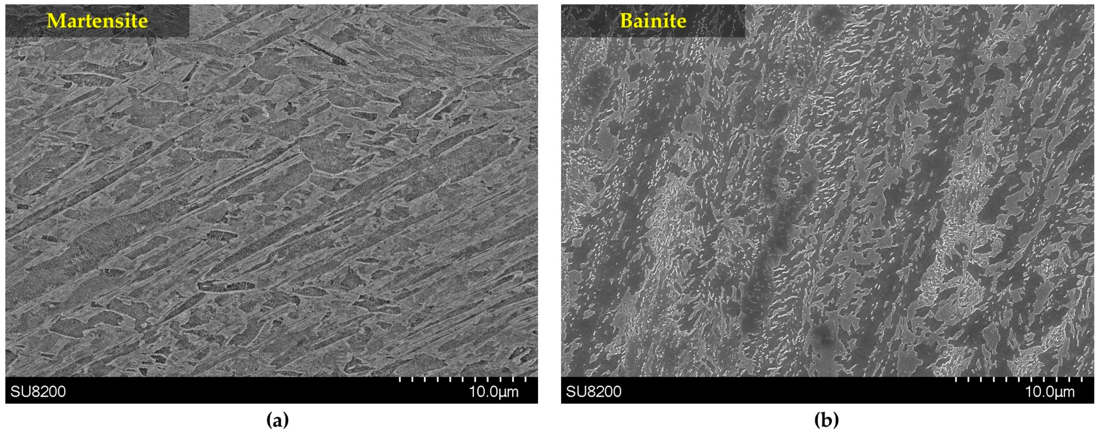
A high-resolution TA DIL 805A/D dilatometer (TA instruments, New Castle, DE, USA) with a 50-nm resolution was used to perform the heat treatment process and the dilatometry tests. Primarily, the specimens were austenitized at 870 °C for 10 min under vacuum, followed by cooling to room temperature with cooling rates of 4.8 and 180 °C/min in order to reach bainitic and a fully martensitic microstructure, respectively. To determine the optimum cooling rates, several tests using cooling rates from 2.5 °C/min to 1800 °C/min were initially carried out. Figure 2 illustrates the as-cooled martensite with Ms (Martensite start temperature) of 316 °C and bainite with Bs (Bainite start temperature) of 472 °C containing less than 5% and 23.2% of retained austenite, respectively. All the retained austenite measurements were carried out according to ASTM E975.
Subsequently, non-isothermal tempering up to 600 °C with heating rates of 5 and 30 °C/min were performed immediately after cooling to avoid possible segregation due to room temperature aging. To avoid any oxidation and decarburization, the non-isothermal tempering was conducted in the vacuum environment. After non-isothermal tempering, the samples were cooled down with a cooling rate of 600 °C/min. The relevant etchant was Vilella solution and Hitachi-SU8200 field emission gun SEM (scanning electron microscope; Hitachi, Tokyo, Japan) was used for microstructural studies. X-ray diffraction (XRD) with Co Kα radiation in standard θ–2θ mode was performed for phase identification using a Bruker Discover D8-2D diffractometer (Bruker, Madison, WI, USA). All the peaks’ positions recorded by XRD were identified with the powder diffraction files (PDF) of the International Centre for Diffraction Data (ICDD) using the software Diffrac.Eva (version 4.0, Bruker AXS, Karlsruhe, Germany). Further analysis of the dilatometry results, using the first derivative of the dilatometry data, allowed for a more precise determination of the different stages of tempering. MIP image analysis software (MIP4, Nahamin Pardazan Asia, Mashhad, Iran) was used for calculating the orientation angle of the carbides within bainitic ferrite subunits.
3. Results and Discussion
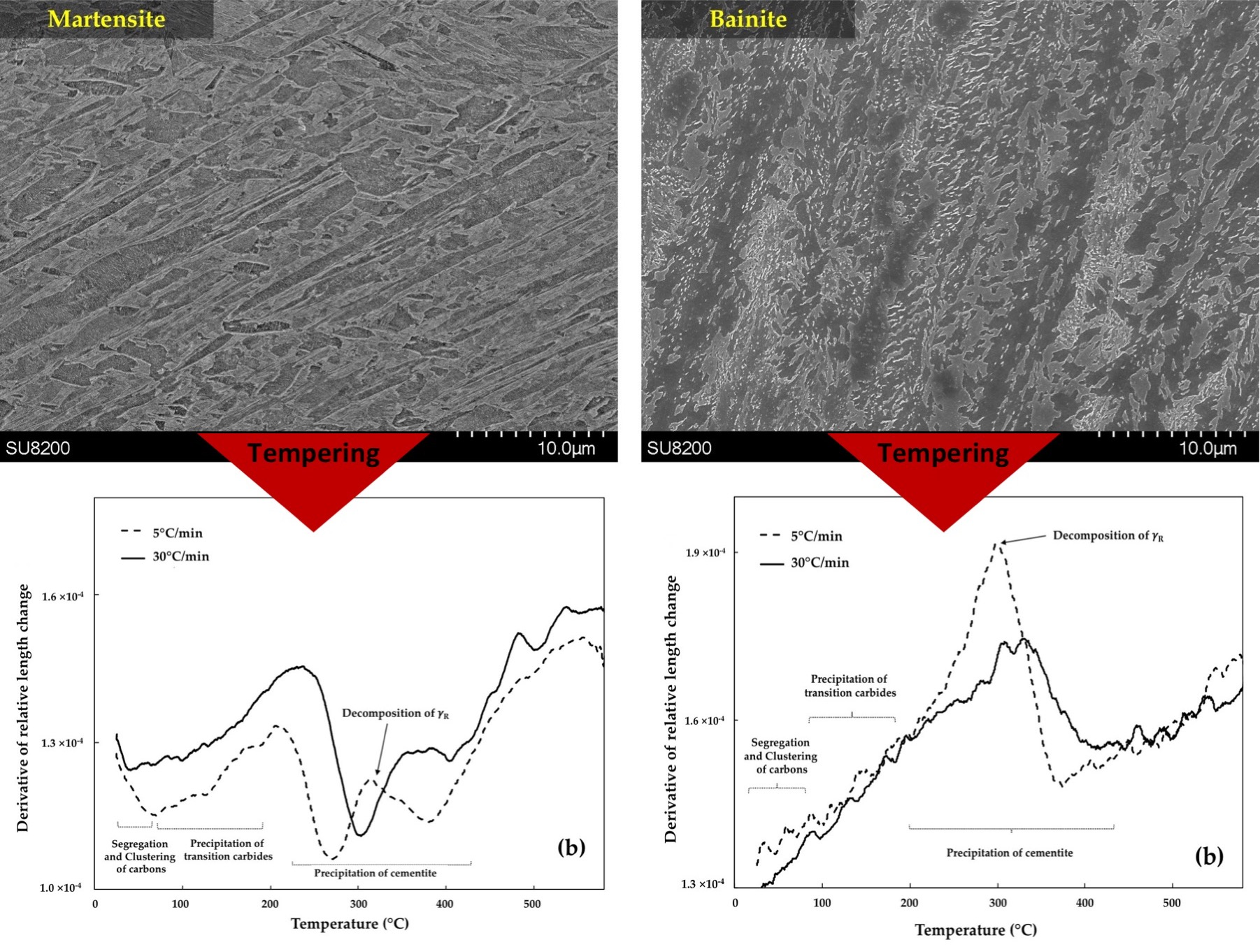
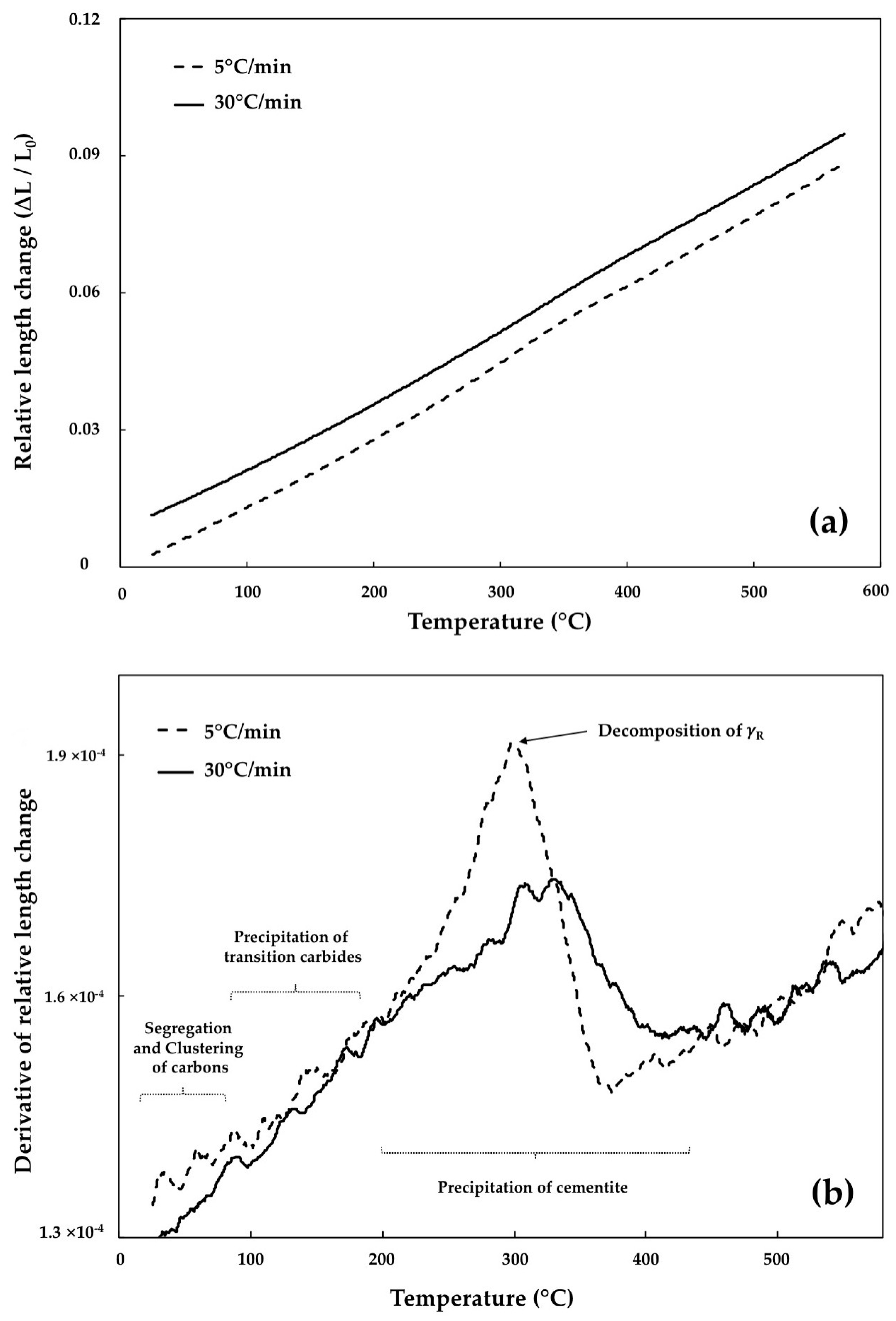
Figure 3a and Figure 4a illustrate the dilatation curves versus temperature during non-isothermal tempering related to the bainitic and martensitic specimens and Figure 3b and Figure 4b their corresponding first derivatives. Where ∆L and L0 are the length change and initial length of the specimen, respectively. In the following sections, dilatometry results are analyzed for each of the four stages of tempering according to the temperature range suggested for each stage.
3.1. Segregation and Clustering of Carbon Atoms
The first stage of tempering causes carbon atom redistribution through the BCC (Body Centered Cubic) iron with carbon segregation to the lattice defects and clustering in the matrix [22]. Examination of the derivative curve in Figure 3b did not reveal any clear indication of length changes for the two heating rates at temperatures below 80 °C. Therefore, carbon segregation and clustering within the solid solution in bainite, which should be accompanied with contractions, were not detected by dilatometry in this investigation. This could probably be related to the small carbon content of bainitic ferrite as discussed below.
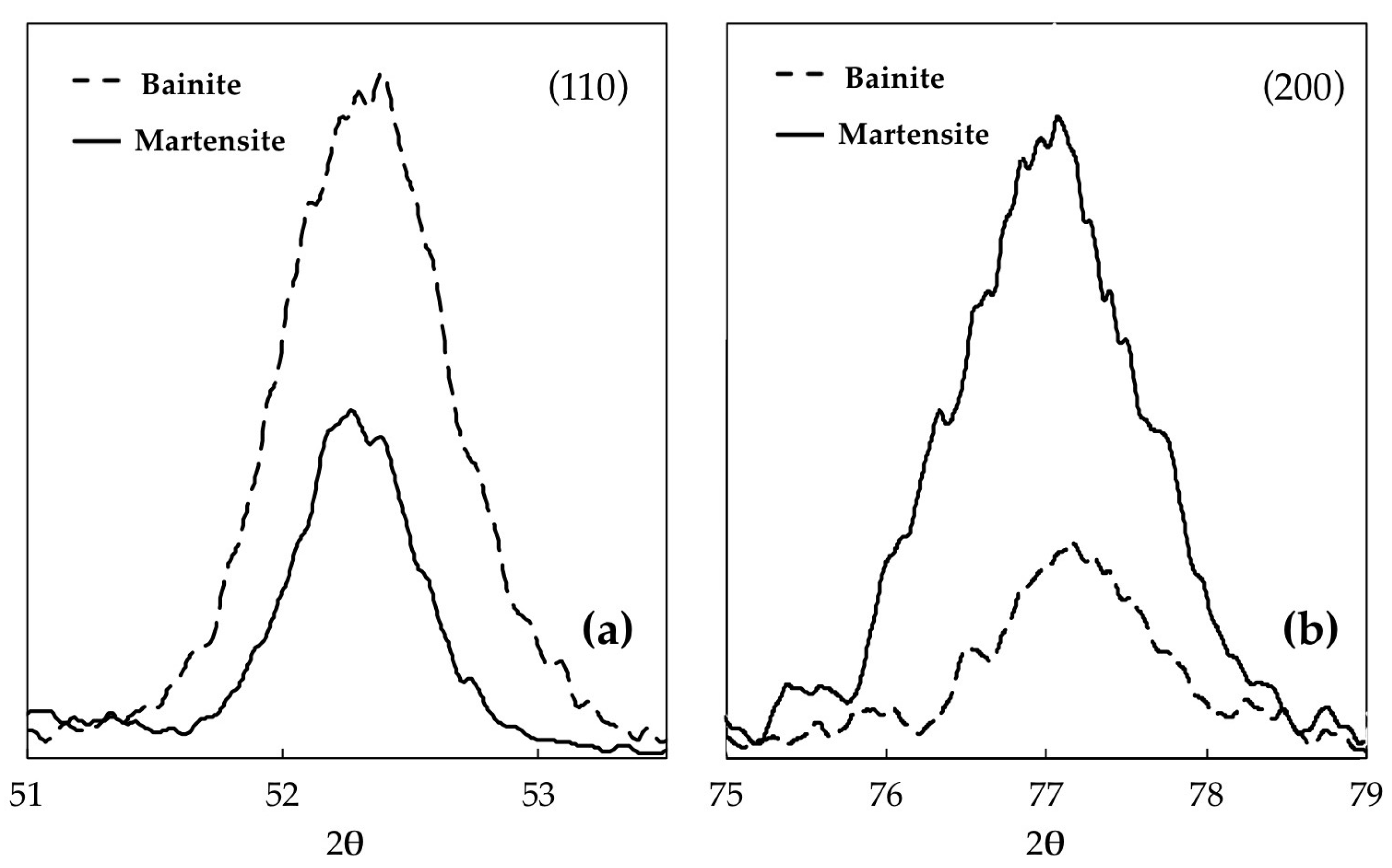
In medium-carbon steels, the carbon content of martensite and bainitic ferrite (before non-isothermal tempering) can be calculated by determining the lattice parameters c and a from (110) and (200) peaks using the following equations [23]:
where λ is the wavelength of the electron beam. Therefore, the carbon content could be defined according to Equations (2) and (3) [23], where a0 is the lattice parameter of BCC iron and a0.30 is the lattice parameter at exactly 0.30 wt % C:
Figure 5 illustrates XRD patterns obtained from bainitic and martensitic specimens for (110) and (200) peaks. From these peaks, lattice parameters were calculated. The lattice parameters and their related carbon contents are listed in Table 1, where [C]c and [C]a are the carbon contents based on Equations (2) and (3), respectively. According to these equations the accuracy of carbon content is ±0.02 wt %.
The calculated carbon content for bainitic ferrite is 0.19 wt % before tempering and 0.23 wt % after tempering while, in martensite, this amount before and after non-isothermal tempering is 0.29 wt % and 0.19 wt %, respectively. These results are in agreement with those reported by Bhadeshia et al. [24] restating that during cooling, most of the available carbon in bainite participated in the formation of cementite particles and a small amount remained in solid solution. The low amount of carbon probably is not enough to show detectable contraction when segregation and clustering take place.
In contrast with the bainitic case, a significant contraction of martensite occurred immediately after starting the tempering (Figure 4). This behavior clearly indicates the occurrence of carbon segregation and clustering below the 80 °C temperature range in a martensitic microstructure. The higher concentration of carbon in martensite, compared to bainite, is probably the main cause for such observation and detection of the contraction by the high-resolution dilatometer during this stage of tempering.
3.2. Precipitation of the ε/η Transition Carbides
The high-resolution dilatometry results presented above (Figure 3), do not demonstrate any length decrement corresponding to ε-carbide precipitation during tempering of bainite. The amount of carbides in bainite and, therefore, carbon content of supersaturated bainitic ferrite, depends on steel composition, for instance, high silicon content delays carbide precipitation and leads to supersaturated bainitic ferrite [25]. The ε-carbide precipitation during tempering of bainite has been reported by Caballero et al. for a steel containing 1.46 wt % Si using atom probe field ion microscopy [26]. However, in the present case, the bainitic ferrite of the investigated steel is not supersaturated in carbon (0.19 wt % C) and, therefore, the precipitation of transition carbides is not expected. Speich and Leslie [11] reported that during the bainitic reaction there is a brief period for carbon redistribution and carbide precipitation called auto-tempering. Thus, the precipitation of transition carbides could presumably occur in the present steel during the formation of bainite and auto-tempering.
Contrary to tempered bainite, this stage is observed during tempering of martensite (Figure 4) because of the higher carbon amount (0.29 wt % C) in martensite. As reported in Figure 4, the start of phase transformation (length reduction) corresponding to the transition carbides overlap with the preceding phase transformation. It can also be seen that, when the higher heating rate of 30 °C/min is applied, the finish temperature is increased by 47 °C, reaching 217 °C. Jack [27] and Nakamura et al.’s [28] characterizations of the transition carbides demonstrated that tempering of martensite leads to the precipitation of ε and η transition carbides in the primarily martensitic phase.
3.3. Retained Austenite Decomposition
The decomposition of retained austenite occurs with an increase in length. Based on XRD measurements, the bainitic specimen contains 23.2% of retained austenite. Dilatometry results revealed a broad peak related to the decomposition of retained austenite that spans from 255 °C to approximately 355 °C for the heating rate of 5 °C/min. For the martensitic structure, this peak falls completely within the cementite precipitation zone and occurs in the range of 269 °C to 401 °C. It is worth noting that the XRD patterns did not show any austenite peaks in the martensitic sample, indicating the absence or a presence of less than 5% (detection limit of XRD) of retained austenite. Comparison between Figure 3 and Figure 4 shows a clear shift of the decomposition peaks to higher temperatures, respectively 21 °C and 31 °C for bainite and martensite.
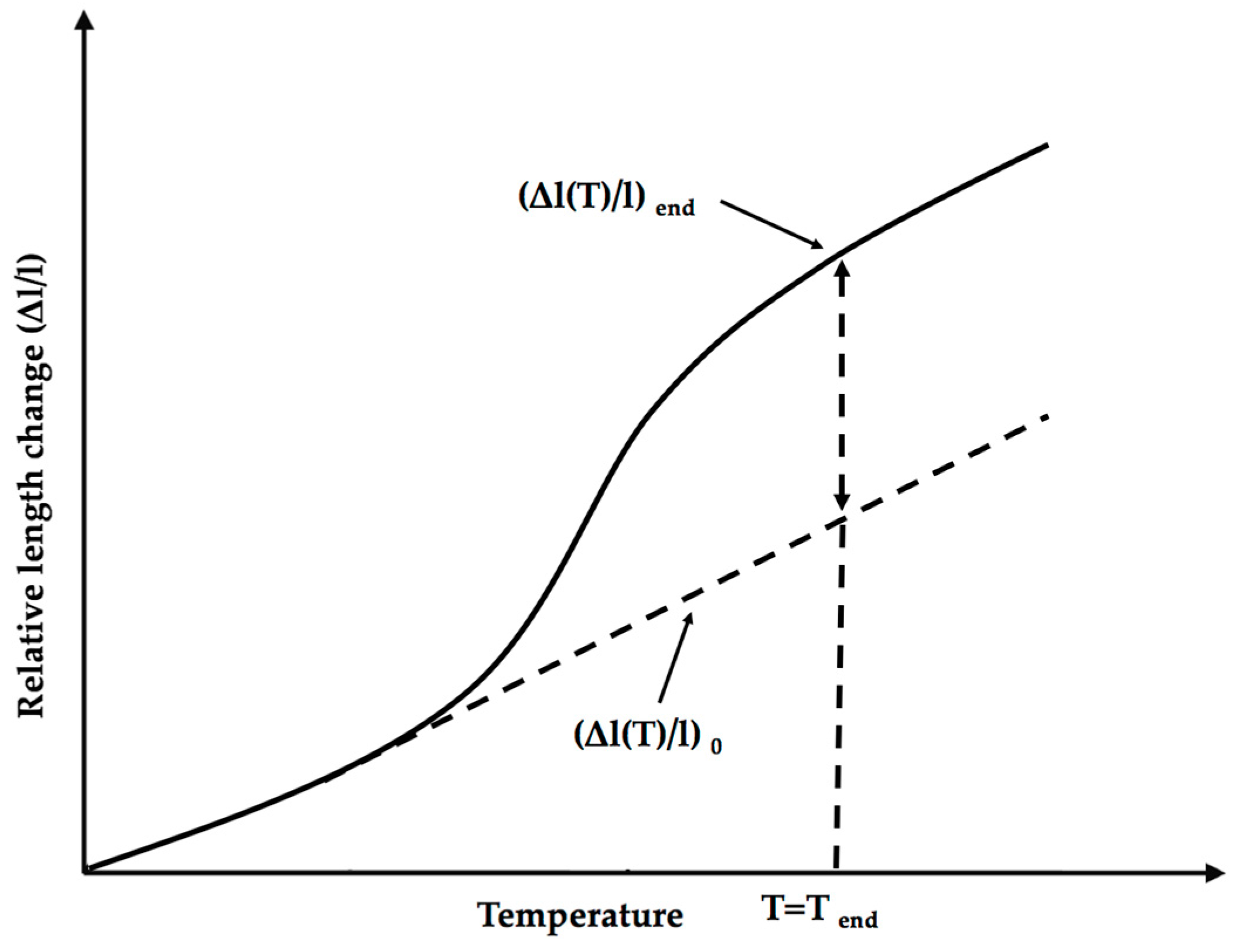
Table 2 summarizes the temperature range and relative length changes corresponding to the high and low heating rates. The degree of relative length increase is associated with the cooling rate and retained austenite percentage. These relative length changes during non-isothermal tempering are determined near the inflection points of dilatometry curves using Equation (4) [20]:
where and are the increase for relative length of the end and start points at temperature T, as it is represented schematically in Figure 6.
It can be seen from the data that the extent of decomposed retained austenite is associated with the heating rate. The relative volume increase corresponding to the bainitic specimen is 3.74% and 2.21% after non-isothermal tempering at the heating rate of 5 °C/min and 30 °C/min, respectively. On the other hand, the relative volume change is approximately constant in the martensitic specimen for both heating rates. These results point out that since the bainitic specimen contains a large amount of retained austenite, the portion of decomposed retained austenite has been influenced by the heating rate; therefore, after tempering at the heating rate of 30 °C/min still some non-decomposed retained austenite remains in the microstructure. In contrast, because the amount of retained austenite is very low in the martensitic structure, decomposition is almost finished even at the heating rate of 30 °C/min and no impact is observed on the relative length change value.
3.4. Cementite Precipitation
The shape of the peak at temperature range related to the cementite precipitation varies with the microstructure. In Figure 3, there is no contraction between about 250 °C and 450 °C. Therefore, cementite precipitation was not observed for bainite. On the other hand, at the same temperature range, an intense contraction was observed in martensite associated with cementite precipitation (Figure 4). This phenomenon overlapped with retained austenite decomposition peak.
Good agreement was found with XRD results presented in Figure 7 and Figure 8. In Figure 7, the presence of chromium carbide (Cr7C3) and some retained austenite are demonstrated in the bainite. Upon non-isothermal tempering at a heating rate of 5 °C/min, Fe3C and Cr7C3 carbides precipitate as a consequence of retained austenite decomposition.
In the case of martensite (Figure 8), no carbides can be seen in martensite, whereas the presence of carbides in tempered martensite is evidence of a large dilatation decrease during non-isothermal tempering depicted in Figure 4b. The peak related to cementite is seen after tempering for both specimens, since cementite phase is detectable by XRD, 5% or more cementite exists in tempered steels. These Fe3C carbides, dissolve upon tempering to form Cr7C3 carbides at the same location [29].
As discussed earlier, in bainite, the bainitic ferrite contains 0.19 wt % of carbon. Since there is a small amount of carbon in solid solution, the cementite precipitation during non-isothermal tempering is negligible [24]. By contrast, in supersaturated martensite with 0.29 wt % of carbon, this phase transformation takes place upon tempering between about 210 °C and 480 °C with a considerable length decrease. Similar observation for cementite precipitation in martensite was reported by Morra et al. [4]. The gradual shift of the transformation temperature to the higher values with increasing the heating rates is due to the time and temperature dependency of carbon diffusion into lattice defects.
It is also worth noting that after completing this non-isothermal tempering and cooling to the ambient temperature, final relative length, calculated by Equation (4), dropped by 0.65% in the martensitic sample after tempering, whereas by contrast, it rises by 0.44% in the bainitic specimen.
Analyses of cooling cycles after each non-isothermal tempering are represented in Figure 9 to investigate the formation of new phases during cooling. In Figure 9a, it can be seen that the first derivation of the relative length change is almost constant during cooling. The pattern is similar for the other three cooling cycles. Thus, it can be concluded that no new phase transformation occurred during the fast cooling after non-isothermal tempering.
3.5. Microstructural Evolution during Tempering
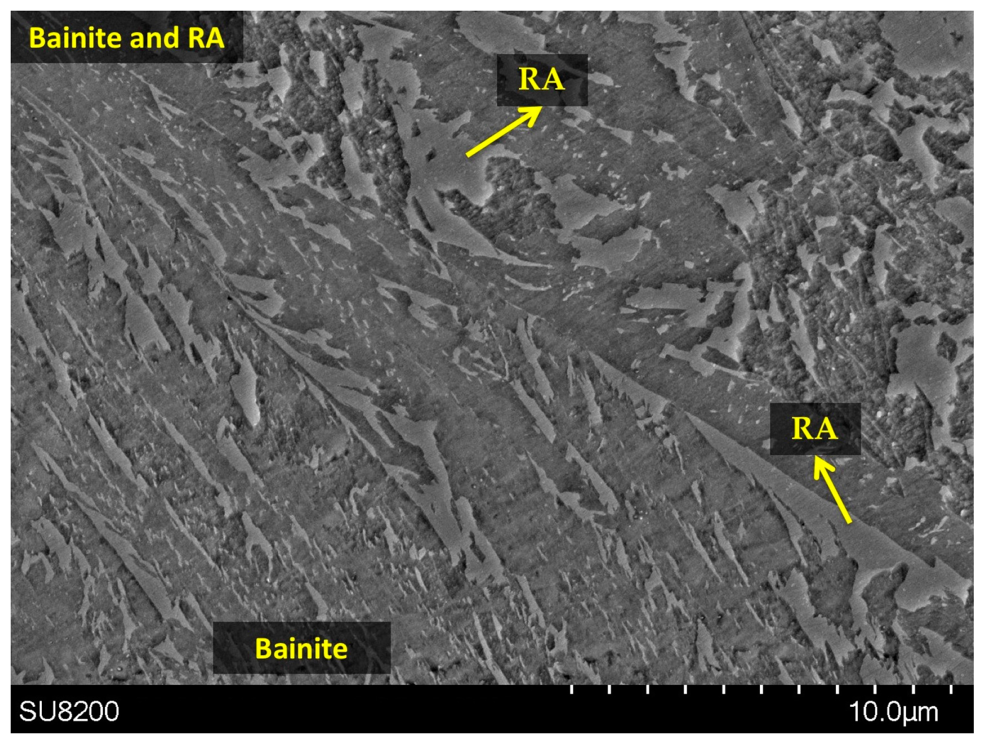
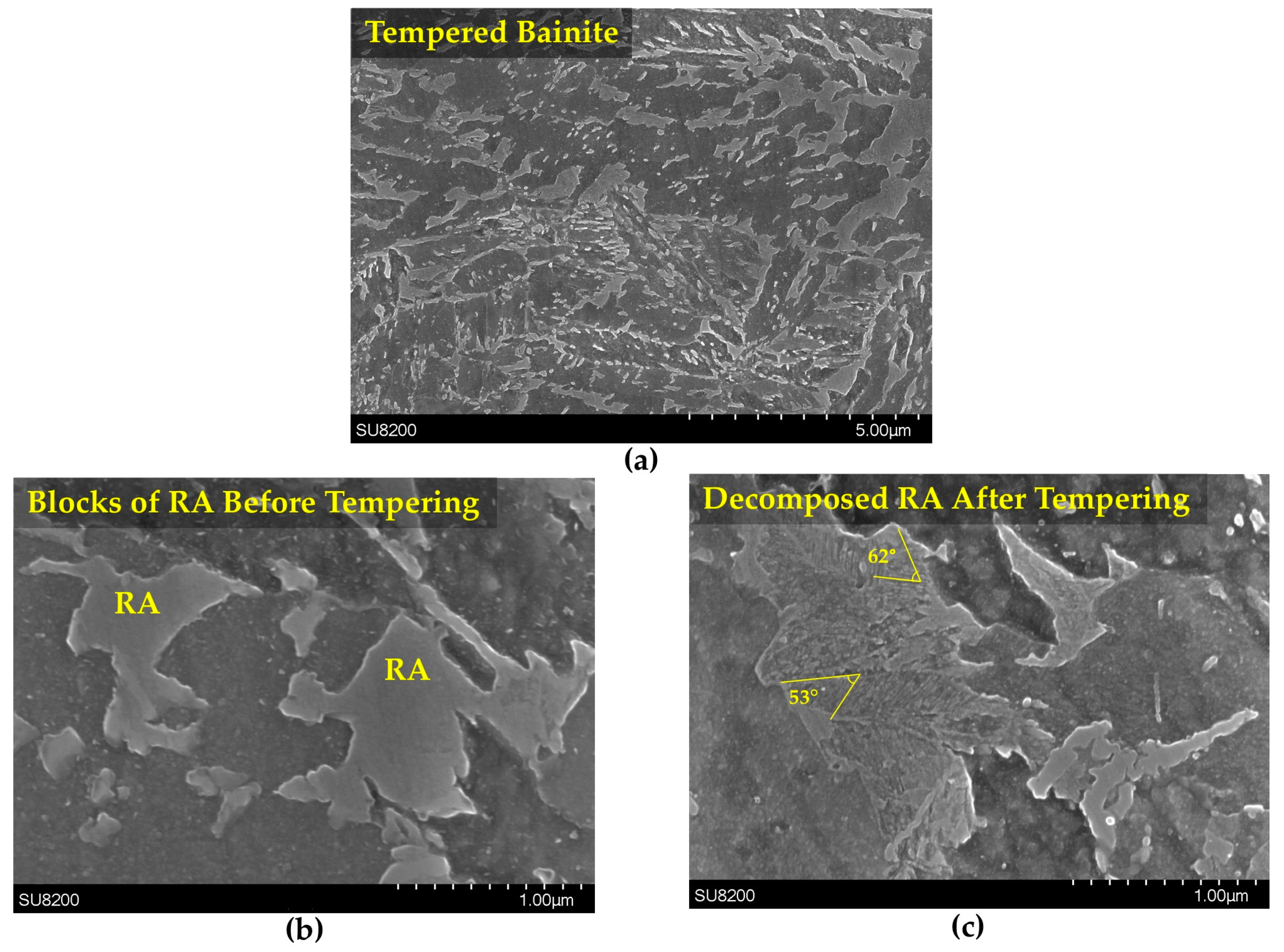
In order to study the detailed morphology after tempering, SEM observation was performed for both martensitic and bainitic specimens, before and after non-isothermal tempering. Figure 10a shows SEM images of tempered bainite after heating at the rate of 5 °C/min. Examination of the microstructure before tempering revealed the presence of several retained austenite islands with blocky morphologies at the grain boundaries of the bainitic ferrites and are characterized by a smooth surface under SEM (Figure 10b). As discussed in Section 3.3, these retained austenite islands decompose in the range of 255 °C to 355 °C and as reported in Figure 10c, their smooth surface becomes roughened with the presence of very fine carbides distributed regularly over the surface. According to Yan et al. [8], the decomposition of retained austenite may lead to the formation of martensite or lower bainite depending on the applied temperature and holding time during tempering.
In Figure 10c, the small carbides ordered in parallel bands among bainitic ferrite subunits were observed at the grain boundaries of bainitic ferrite. The axes of these carbides were inclined between 53° and 62° to the growth direction of the bainitic ferrite. It has been reported that the angle between carbides in the lower bainite ferrite inclines at about 60° to the growth direction of ferrite, which is very close to the angles measured in the present investigation [30]. It should also be noted that in agreement with reported results in the literature, the morphology of decomposed retained austenite blocks is very similar to that of lower bainite [31]. On the basis of the above analysis, it can, therefore, reasonably said that the decomposition of retained austenite results in the formation of lower bainite in the investigated steel.
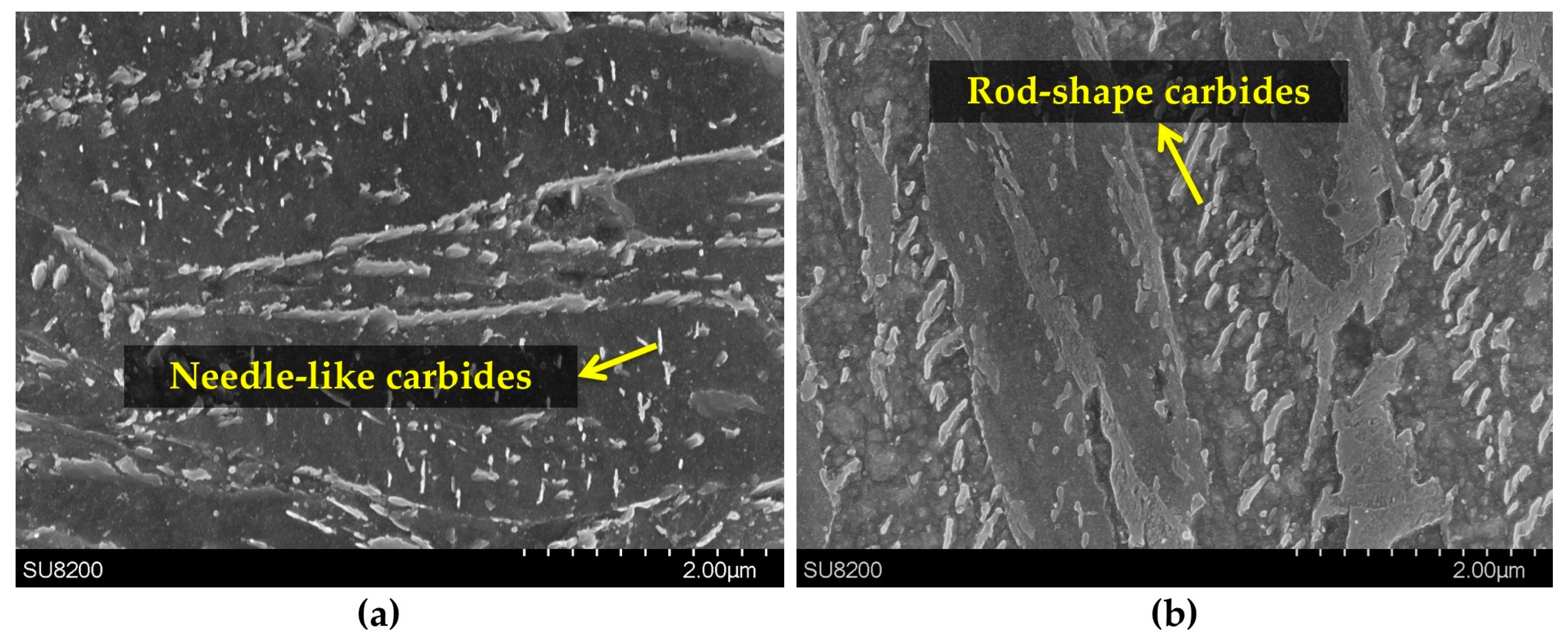
The tempered martensitic and bainitic microstructures at heating rates of 30 °C/min are illustrated in Figure 11. Figure 11a shows that the microstructure of tempered martensite consists in martensite plates with fine needle-like carbides, composed of cementite and chromium carbide, within the plates. Analyses of tempered bainite (Figure 11b), shows the presence of coarse rod-shape carbides. This indicates carbide coarsening rather than precipitation has taken place during non-isothermal tempering of bainite. Since most of carbides have been formed during bainitic transformation; they have, therefore, more time to grow during non-isothermal tempering.
4. Conclusions
The non-isothermal tempering behavior of a bainitic microstructure of a medium-carbon high-strength steel was investigated for two different heating rates. A martensitic structure was also used as a reference for comparison purposes. Phase transformations were studied using high-resolution dilatometry and the microstructural features were examined using optical and scanning electron microscopes. The results indicated that tempering effects vary significantly from bainitic to martensitic microstructures helping to draw a clearer picture of the phase transformations in different microstructures. The following conclusions can be drawn from the present study:
- (1)
- In the bainitic microstructure, retained austenite decomposed to lower bainite associated with volume expansion during tempering in contrast to martensite tempering where great length decrease occurred due to decomposition of medium-carbon martensite to low carbon martensite plus carbides.
- (2)
- Phase transformations during tempering of martensite occurred at slightly higher temperatures than bainite tempering, owing to the auto-tempering effect through bainite formation.
- (3)
- In tempering of the bainitic specimens which contain 23.2% of retained austenite, its decomposition at the heating rate of 5 °C/min caused 3.74% length increase. This percentage decreased steeply to 2.21% when the heating rate increased to 30 °C/min, demonstrating that some amount of retained austenite remained untransformed after non-isothermal tempering at this heating rate, whilst in martensite, the length increase for both heating rates is almost constant indicating completed transformation.
Acknowledgments
The authors are very grateful to Finkl Steel Co. for providing the samples of the present research. The authors would like to appreciate the National Science and Engineering Research Council, Ottawa, ON, Canada for their financial support in the framework of a Collaborative Research and Development project (CRDJP 453683).
Author Contributions
A first draft of the manuscript was written by S. Hesamodin Talebi, which received substantial review from other authors. S. Hesamodin Talebi designed the study. S. Hesamodin Talebi and Hadi Ghasemi-Nanesa performed the experiments and analyzed the results. Mohammad Jahazi is the main supervisor and contributed to analyzing the results and writing the manuscript. Haikouhi Melkonyan is the industrial researcher at Finkl Steel, and prepared the material and evaluated the manuscript.
Conflicts of Interest
The authors declare no conflict of interest.
References
- Firrao, D.; Matteis, P.; Russo Spena, P.; Gerosa, R. Influence of the microstructure on fatigue and fracture toughness properties of large heat-treated mold steels. Mater. Sci. Eng. A 2013, 559, 371–383. [Google Scholar] [CrossRef]
- Firrao, D.; Gerosa, R.; Ghidini, A.; Matteis, P.; Mortarino, G.; Pinasco, M.R.; Rivolta, B.; Silva, G.; Stagno, E. Relation between fatigue crack initiation and propagation, toughness and microstructure in large steel blooms for automotive plastic molds. Int. J. Fatigue 2007, 29, 1880–1884. [Google Scholar] [CrossRef]
- Chentouf, S.M.; Jahazi, M.; Lapierre-Boire, L.P.; Godin, S. Characteristics of austenite transformation during post forge cooling of large-size high strength steel ingots. Metallogr. Microstruct. Anal. 2014, 3, 281–297. [Google Scholar] [CrossRef]
- Morra, P.; Böttger, A.; Mittemeijer, E. Decomposition of iron-based martensite. A kinetic analysis by means of differential scanning calorimetry and dilatometry. J. Therm. Anal. Calorim. 2001, 64, 905–914. [Google Scholar] [CrossRef]
- Biss, V.; Cryderman, R.L. Martensite and retained austenite in hot-rolled, low-carbon bainitic steels. Metall. Mater. Trans. B 1971, 2, 2267–2276. [Google Scholar] [CrossRef]
- Gojić, M.; Sućeska, M.; Rajić, M. Thermal analysis of low alloy Cr-Mo steel. J. Therm. Anal. Calorim. 2004, 75, 947–956. [Google Scholar] [CrossRef]
- Rodrigues, P.C.M.; Pereloma, E.V.; Santos, D.B. Mechanical properities of an HSLA bainitic steel subjected to controlled rolling with accelerated cooling. Mater. Sci. Eng. A 2000, 283, 136–143. [Google Scholar] [CrossRef]
- Yan, G.; Han, L.; Li, C.; Luo, X.; Gu, J. Characteristic of retained austenite decomposition during tempering and its effect on impact toughness in SA508 Gr.3 steel. J. Nucl. Mater. 2017, 483, 167–175. [Google Scholar] [CrossRef]
- Cheng, L.; Brakman, C.M.; Korevaar, B.M.; Mittemeijer, E.J. The tempering of iron- carbon martensite; dilatometric and calorimetric analysis. Metall. Trans. A 1988, 19, 2415–2426. [Google Scholar] [CrossRef]
- Nagakura, S.; Hirotsu, Y.; Kusunoki, M.; Suzuki, T.; Nakamura, Y. Crystallographic study of the tempering of martensitic carbon steel by electron microscopy and diffraction. Metall. Trans. A 1983, 14, 1025–1031. [Google Scholar] [CrossRef]
- Speich, G.R.; Leslie, W.C. Tempering of steel. Metall. Trans. 1972, 3, 1043–1054. [Google Scholar] [CrossRef]
- Primig, S.; Leitner, H. Separation of overlapping retained austenite decomposition and cementite precipitation reactions during tempering of martensitic steel by means of thermal analysis. Thermchim. Acta 2011, 526, 111–117. [Google Scholar] [CrossRef]
- Miller, M.; Beaven, P.; Smith, G. A study of the early stages of tempering of iron-carbon martensites by atom probe field ion microscopy. Metall. Trans. A 1981, 12, 1197–1204. [Google Scholar] [CrossRef]
- Taylor, K.; Olson, G.; Cohen, M.; Sande, J.B.V. Carbide precipitation during stage I tempering of Fe-Ni-C martensites. Metall. Mater. Trans. A 1989, 20, 2749–2765. [Google Scholar] [CrossRef]
- Olson, G.B.; Cohen, M. Early stages of aging and tempering of ferrous martensites. Metall. Trans. A 1983, 14, 1057–1065. [Google Scholar] [CrossRef]
- Mittemeher, E.J.; Cheng, L.; van der Schaaf, P.J.; Brakman, C.M.; Korevaar, B.M. Analysis of nonisothermal transformation kinetics; tempering of iron-carbon and iron-nitrogen martensites. Metall. Trans. A 1988, 19, 925–932. [Google Scholar] [CrossRef]
- Saha Podder, A.; Bhadeshia, H.K.D.H. Thermal stability of austenite retained in bainitic steels. Mater. Sci. Eng. A 2010, 527, 2121–2128. [Google Scholar] [CrossRef]
- Ghasemi Nanesa, H.; Jahazi, M. Alternative phase transformation path in cryogenically treated AISI D2 tool steel. Mater. Sci. Eng. A 2015, 634, 32–36. [Google Scholar] [CrossRef]
- Jung, M.; Lee, S.J.; Lee, Y.K. Microstructural and dilatational changes during tempering and tempering kinetics in martensitic medium-carbon steel. Metall. Mater. Trans. A 2009, 40, 551–559. [Google Scholar] [CrossRef]
- Leiva, J.A.V.; Morales, E.V.; Villar-Cociña, E.; Donis, C.A.; de S. Bott, I. Kinetic parameters during the tempering of low-alloy steel through the non-isothermal dilatometry. J. Mater. Sci. 2009, 45, 418. [Google Scholar] [CrossRef]
- Peet, M.J.; Babu, S.S.; Miller, M.K.; Bhadeshia, H.K.D.H. Tempering of low-temperature bainite. Metall. Mater. Trans. A 2017, 48, 3410–3418. [Google Scholar] [CrossRef]
- Krauss, G. Tempering of Lath Martensite in Low and Medium Carbon Steels: Assessment and Challenges. Steel Res. Int. 2017. [Google Scholar] [CrossRef]
- Kang, M.K.; Ai, Y.L.; Zhang, M.X.; Yang, Y.Q.; Zhu, M.; Chen, Y. Carbon content of bainite ferrite in 40CrMnSiMoV steel. Mater. Chem. Phys. 2009, 118, 438–441. [Google Scholar] [CrossRef]
- Bhadeshia, H.K.D.H. Bainite in Steels: Transformations, Microstructure and Properties, 2nd ed.; IOM Communications: London, UK, 2001. [Google Scholar]
- Caballero, F.G.; Miller, M.K.; Babu, S.S.; Garcia-Mateo, C. Atomic scale observations of bainite transformation in a high carbon high silicon steel. Acta Mater. 2007, 55, 381–390. [Google Scholar] [CrossRef] [Green Version]
- Caballero, F.G.; Miller, M.K.; Garcia-Mateo, C.; Capdevila, C.; Babu, S.S. Redistribution of alloying elements during tempering of a nanocrystalline steel. Acta Mater. 2008, 56, 188–199. [Google Scholar] [CrossRef] [Green Version]
- Jack, K. Structural transformations in the tempering of high-carbon martensitic steels. J. Iron Steel Inst. 1951, 169, 26–36. [Google Scholar]
- Nakamura, Y.; Nagakura, S. Structure of iron-carbon martensite in the transition state from the first to the third stage of tempering studied by electron microscopy and diffraction. Trans. Jpn. Inst. Met. 1986, 27, 842–848. [Google Scholar] [CrossRef]
- Dépinoy, S.; Toffolon-Masclet, C.; Urvoy, S.; Roubaud, J.; Marini, B.; Roch, F.; Kozeschnik, E.; Gourgues-Lorenzon, A.F. Carbide precipitation in 2.25Cr-1Mo bainitic steel: Effect of heating and isothermal tempering conditions. Metall. Mater. Trans. A 2017, 48, 2164–2178. [Google Scholar] [CrossRef]
- Shimizu, K.; Ko, T.; Nishiyama, Z. Transmission electron microscope observation of the bainite of carbon steel. Trans. Jpn. Inst. Met. 1964, 5, 225–230. [Google Scholar] [CrossRef]
- Porter, D.A.; Easterling, K.E.; Sherif, M. Phase Transformations in Metals and Alloys (Revised Reprint), 3rd ed.; CRC Press: Boca Raton, FL, USA, 2009. [Google Scholar]
Figure 1.
SEM (scanning electron microscope) image illustrating as-received microstructure composed of bainite and retained austenite (RA).
Figure 1.
SEM (scanning electron microscope) image illustrating as-received microstructure composed of bainite and retained austenite (RA).

Figure 2.
As-cooled microstructures obtained for different cooling rates: (a) Martensitic microstructure, 180 °C/min and (b) bainitic microstructure, 4.8 °C/min.
Figure 2.
As-cooled microstructures obtained for different cooling rates: (a) Martensitic microstructure, 180 °C/min and (b) bainitic microstructure, 4.8 °C/min.

Figure 3.
(a) Relative length change diagram during non-isothermal tempering of bainitic specimen at heating rates of 5 °C/min and 30 °C/min, and (b) the first derivative curve of the relative length change corresponding to these heating rates.
Figure 3.
(a) Relative length change diagram during non-isothermal tempering of bainitic specimen at heating rates of 5 °C/min and 30 °C/min, and (b) the first derivative curve of the relative length change corresponding to these heating rates.

Figure 4.
(a) Relative length change diagram during non-isothermal tempering of the martensitic specimen at the heating rates of 5 °C/min and 30 °C/min, and (b) the first derivative curve of relative length change corresponding to these heating rates.
Figure 4.
(a) Relative length change diagram during non-isothermal tempering of the martensitic specimen at the heating rates of 5 °C/min and 30 °C/min, and (b) the first derivative curve of relative length change corresponding to these heating rates.
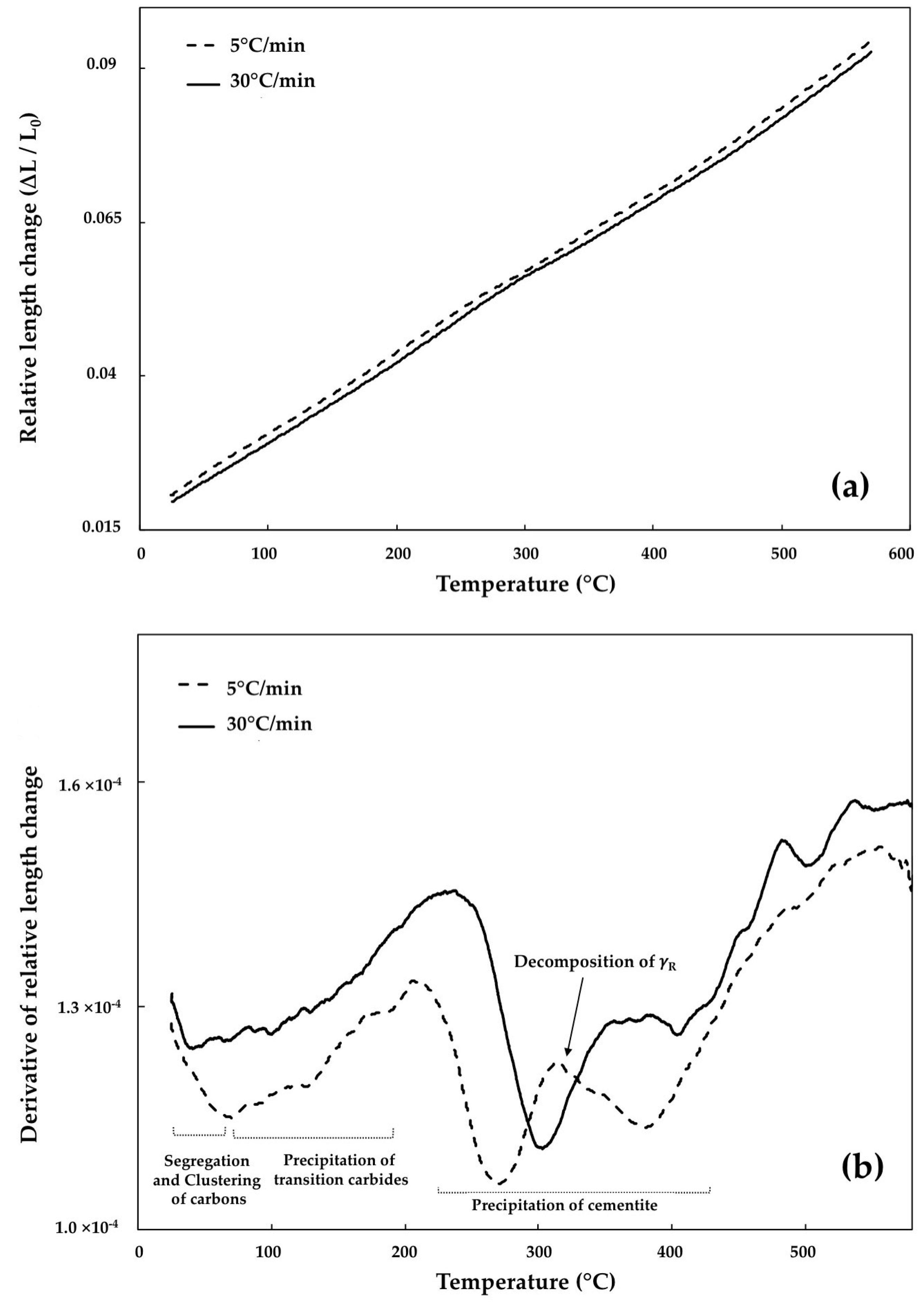
Figure 5.
Two XRD (X-ray diffraction) peaks of bainite and martensite: (a) (110) peak and (b) (200) peak.
Figure 5.
Two XRD (X-ray diffraction) peaks of bainite and martensite: (a) (110) peak and (b) (200) peak.

Figure 6.
Relative length variations near the inflection point.

Figure 7.
XRD spectra of bainite and non-isothermal tempered bainite at heating rate of 5 °C/min.
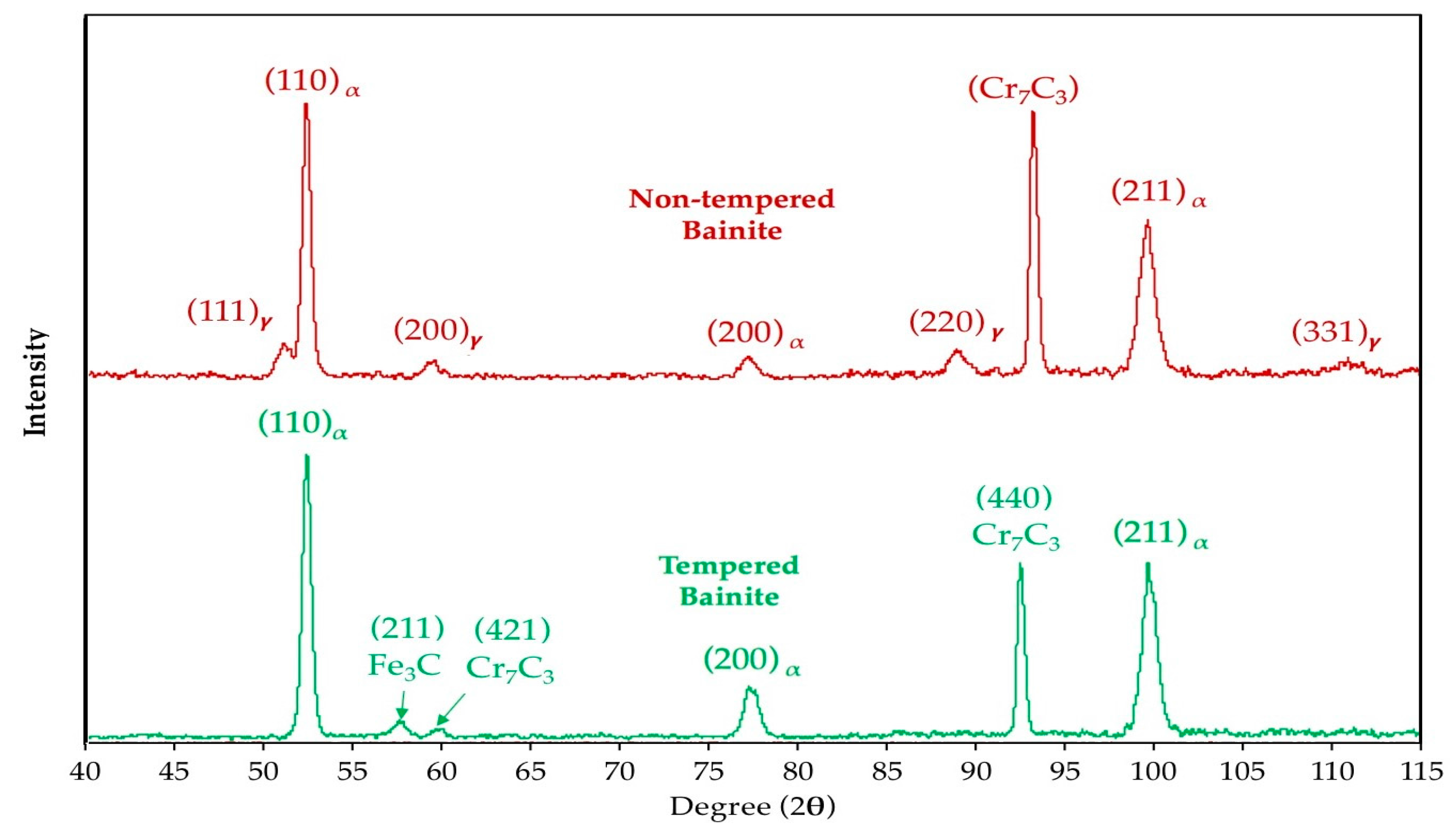
Figure 8.
XRD spectra of martensite and non-isothermal tempered martensite at heating rate of 5 °C/min.
Figure 8.
XRD spectra of martensite and non-isothermal tempered martensite at heating rate of 5 °C/min.
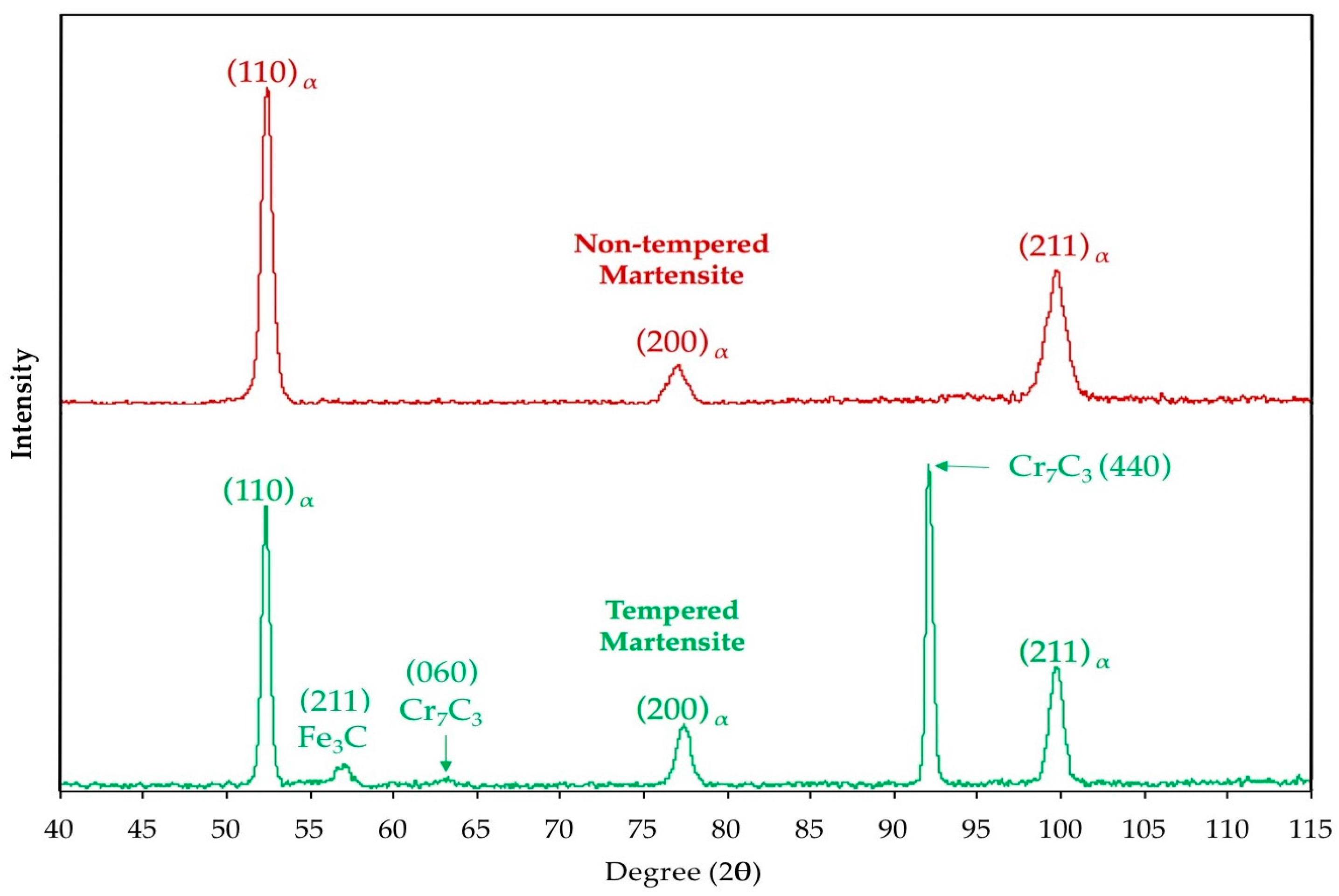
Figure 9.
Relative length change and its derivation during the cooling cycle (from 600 °C to ambient temperature at a cooling rate of 600 °C/min) after tempering of: (a) The bainitic specimen non-isothermally tempered at a heating rate of 5 °C/min; (b) the bainitic specimen non-isothermally tempered at a heating rate of 30 °C/min; (c) the martensitic specimen non-isothermally tempered at a heating rate of 5 °C/min and (d) the martensitic specimen non-isothermally tempered at a heating rate of 30 °C/min.
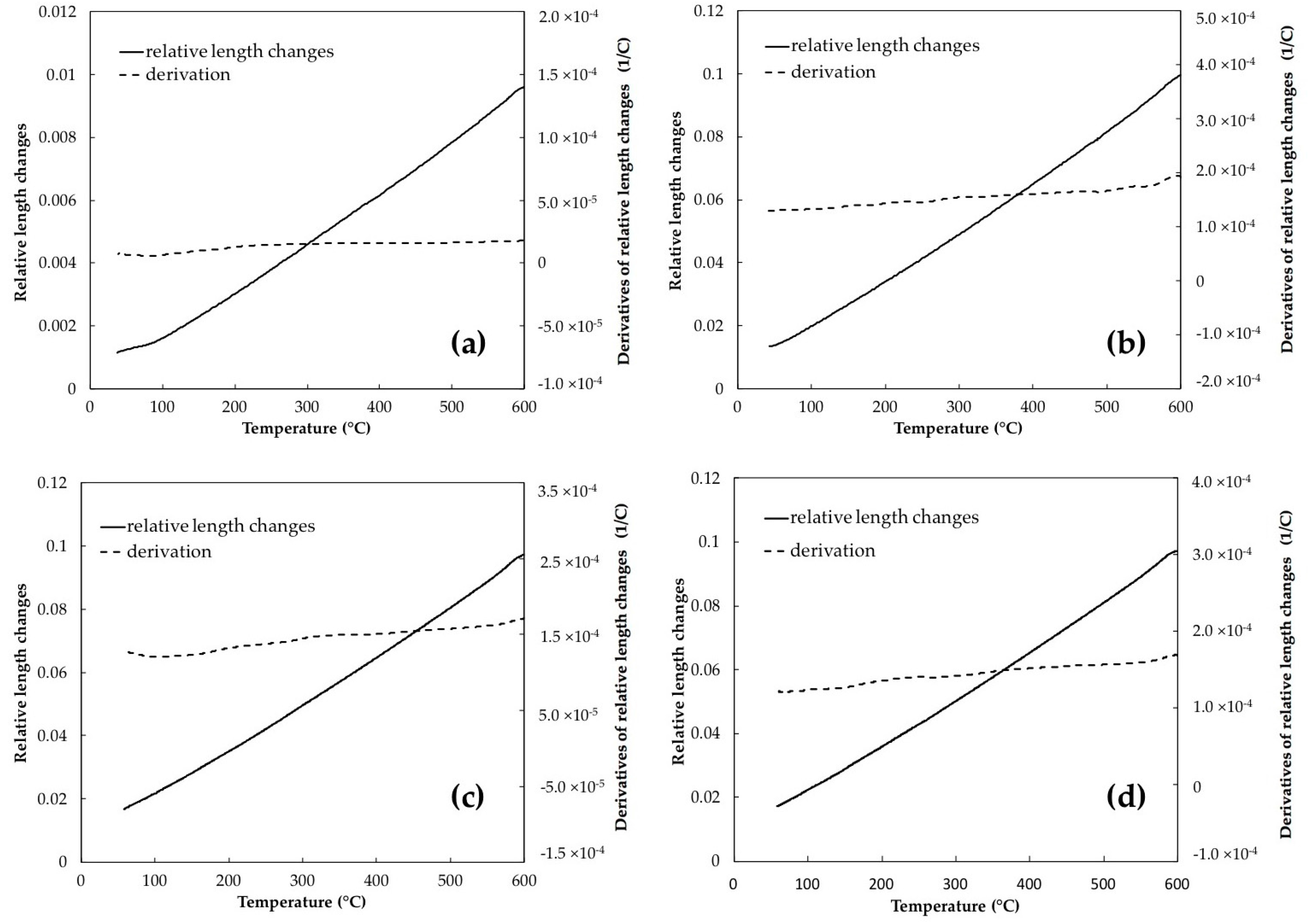
Figure 10.
SEM images of microstructure evolution in the bainitic sample during non-isothermal tempering at heating rate of 5 °C/min: (a) The microstructure after tempering; (b) blocks of retained austenite (RA) prior to tempering and (c) blocks of decomposed retained austenite after tempering.
Figure 10.
SEM images of microstructure evolution in the bainitic sample during non-isothermal tempering at heating rate of 5 °C/min: (a) The microstructure after tempering; (b) blocks of retained austenite (RA) prior to tempering and (c) blocks of decomposed retained austenite after tempering.

Figure 11.
SEM images after non-isothermal tempering at heating rate of 30 °C/min: (a) Plates of tempered martensite with fine needle-like carbides within the plate and (b) tempered bainite with coarser rod-shape carbides.
Figure 11.
SEM images after non-isothermal tempering at heating rate of 30 °C/min: (a) Plates of tempered martensite with fine needle-like carbides within the plate and (b) tempered bainite with coarser rod-shape carbides.

Table 1.
Lattice parameters and carbon contents of the as-received microstructure, bainitic ferrite, and martensite, before and after non-isothermal tempering with a heating rate of 5 °C/min, determined using X-ray diffraction.
Table 1.
Lattice parameters and carbon contents of the as-received microstructure, bainitic ferrite, and martensite, before and after non-isothermal tempering with a heating rate of 5 °C/min, determined using X-ray diffraction.
| Microstructure | c(Å) | a(Å) | [C]c (wt %) | [C]a (wt %) | [C] (wt %) |
|---|---|---|---|---|---|
| As-received (Bainite) | 2.8712 | 2.8668 | 0.24 | 0.30 | 0.26 |
| Bainite | 2.8718 | 2.8650 | 0.26 | 0.11 | 0.19 |
| Tempered Bainite (5 °C/min) | 2.8713 | 2.8634 | 0.24 | 0.22 | 0.23 |
| Martensite | 2.8724 | 2.8702 | 0.30 | 0.27 | 0.29 |
| Tempered Martensite (5 °C/min) | 2.8708 | 2.8689 | 0.21 | 0.17 | 0.19 |
Table 2.
Temperature interval of retained austenite decomposition and percentage of relative length change for maximum and minimum heating rates in both investigated microstructure.
Table 2.
Temperature interval of retained austenite decomposition and percentage of relative length change for maximum and minimum heating rates in both investigated microstructure.
| Specimen | Heating Rate (°C/min) | Temperature Range (°C) | Relative Length Change (%) |
|---|---|---|---|
| Bainite | 5 | 255–359 | +3.74 |
| 30 | 276–386 | +2.21 | |
| Martensite | 5 | 269–370 | +0.67 |
| 30 | 300–401 | +0.63 |
© 2017 by the authors. Licensee MDPI, Basel, Switzerland. This article is an open access article distributed under the terms and conditions of the Creative Commons Attribution (CC BY) license (http://creativecommons.org/licenses/by/4.0/).
Share and Cite
MDPI and ACS Style
Talebi, S.H.; Ghasemi-Nanesa, H.; Jahazi, M.; Melkonyan, H. In Situ Study of Phase Transformations during Non-Isothermal Tempering of Bainitic and Martensitic Microstructures. Metals 2017, 7, 346. https://doi.org/10.3390/met7090346
AMA Style
Talebi SH, Ghasemi-Nanesa H, Jahazi M, Melkonyan H. In Situ Study of Phase Transformations during Non-Isothermal Tempering of Bainitic and Martensitic Microstructures. Metals. 2017; 7(9):346. https://doi.org/10.3390/met7090346
Chicago/Turabian StyleTalebi, S. Hesamodin, Hadi Ghasemi-Nanesa, Mohammad Jahazi, and Haikouhi Melkonyan. 2017. "In Situ Study of Phase Transformations during Non-Isothermal Tempering of Bainitic and Martensitic Microstructures" Metals 7, no. 9: 346. https://doi.org/10.3390/met7090346
Note that from the first issue of 2016, this journal uses article numbers instead of page numbers. See further details here.