Characterisation of Calcium- and Phosphorus-Enriched Porous Coatings on CP Titanium Grade 2 Fabricated by Plasma Electrolytic Oxidation

 ,
, 
Abstract
:1. Introduction
2. Method
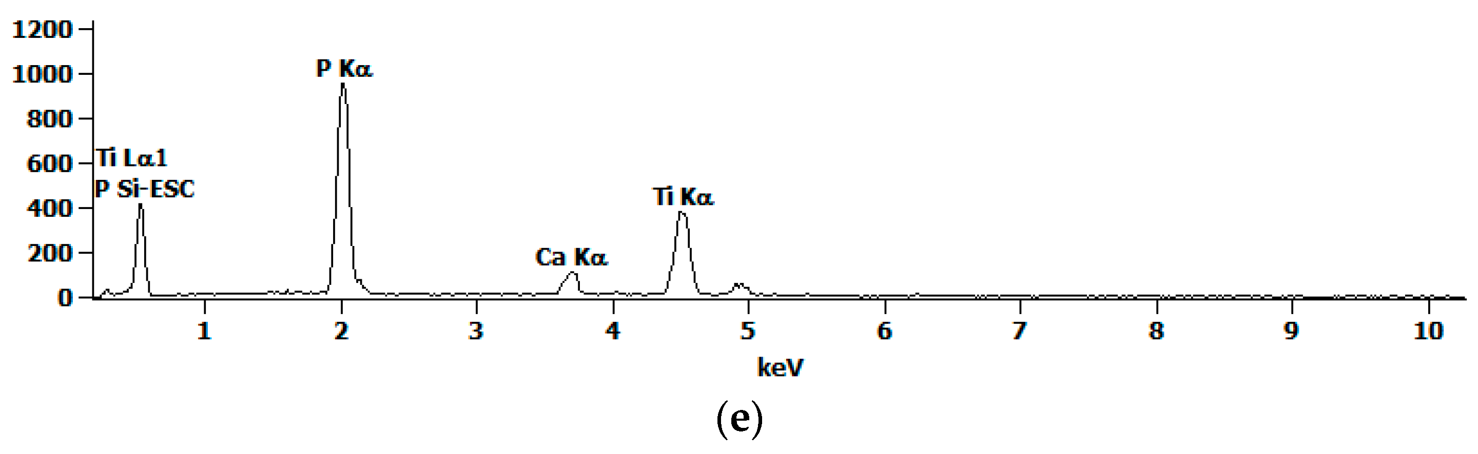
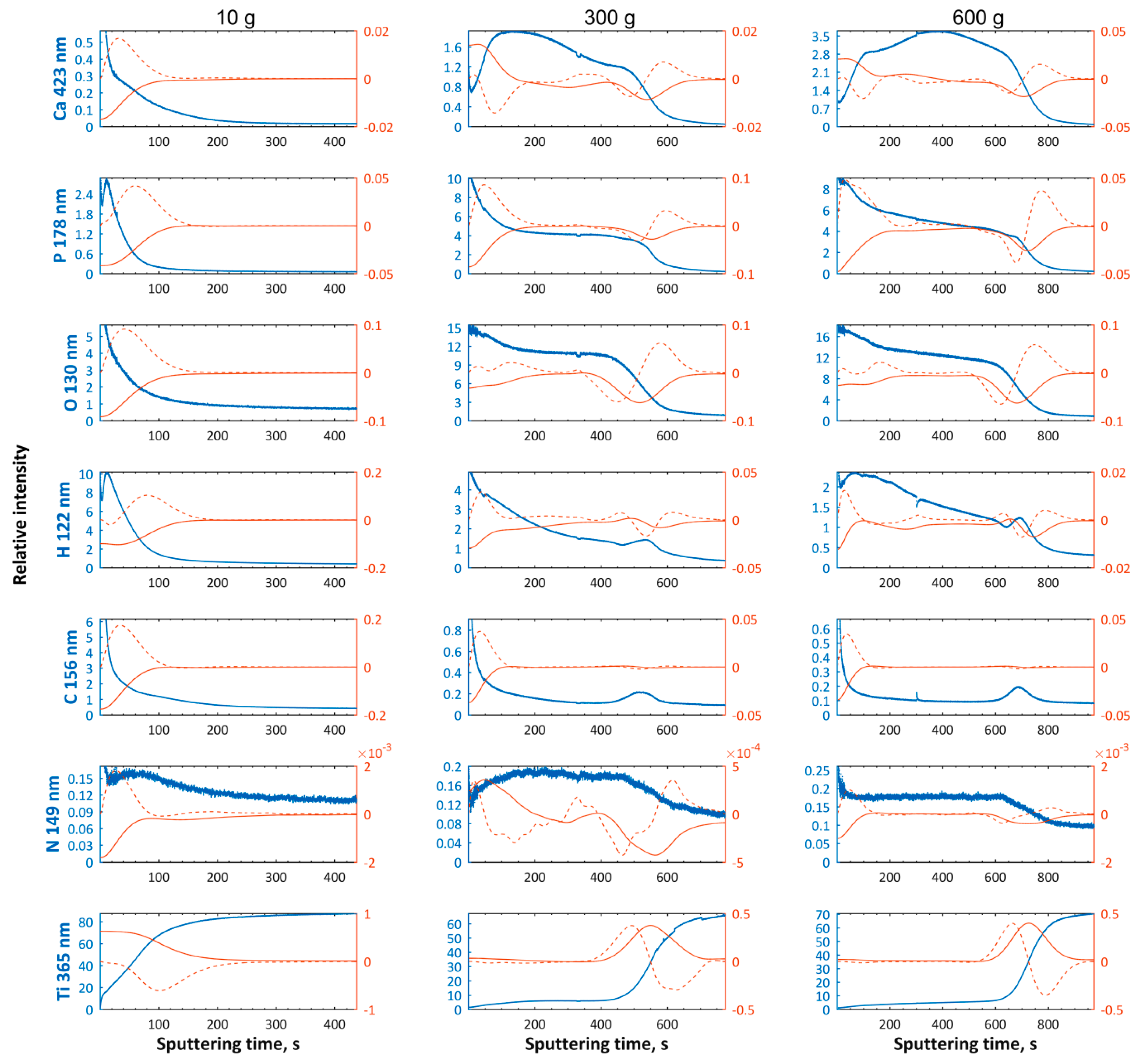
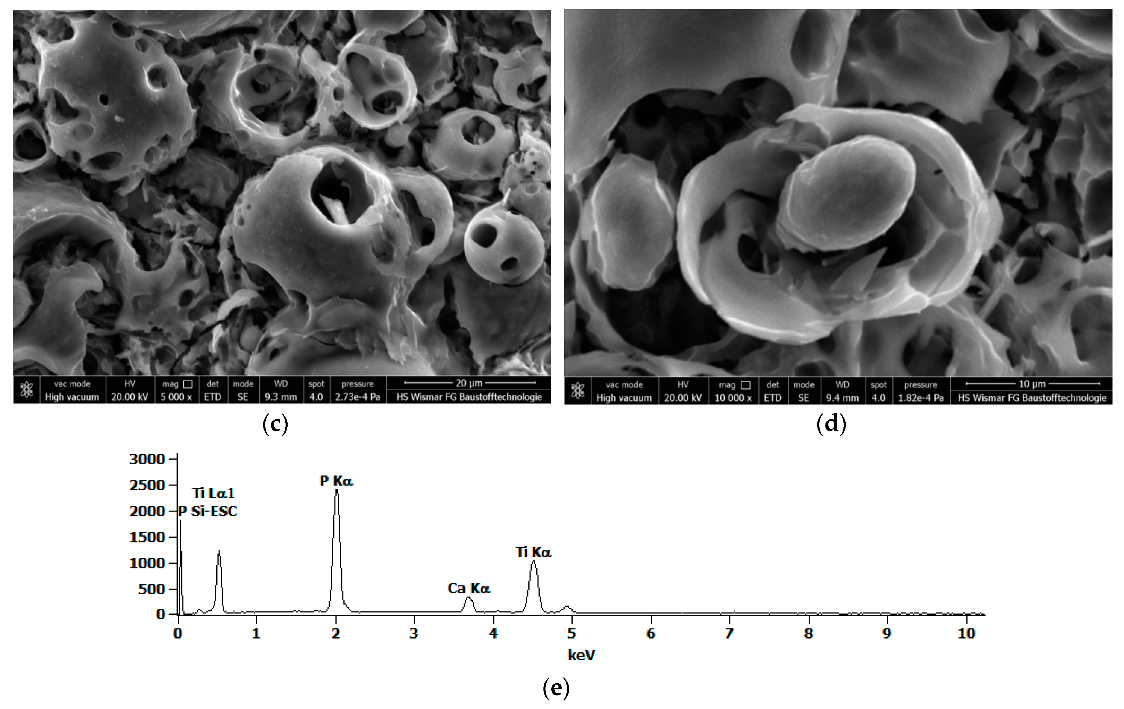
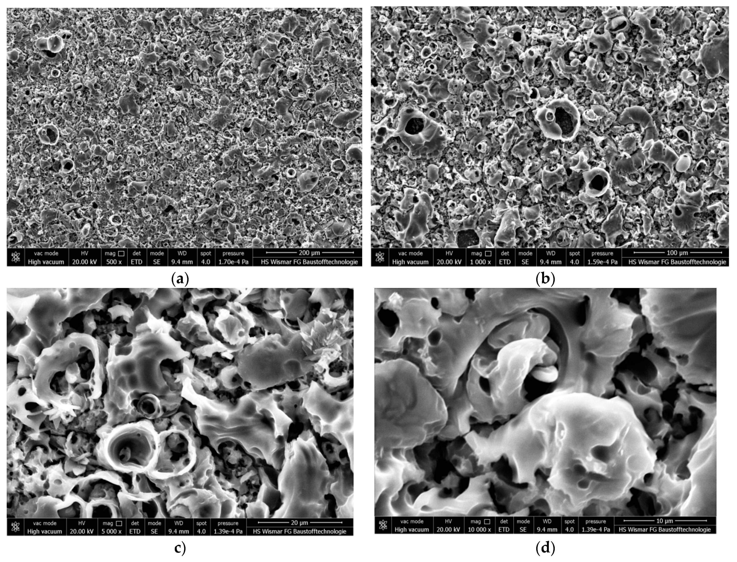
3. Results
4. Conclusions
- (1)
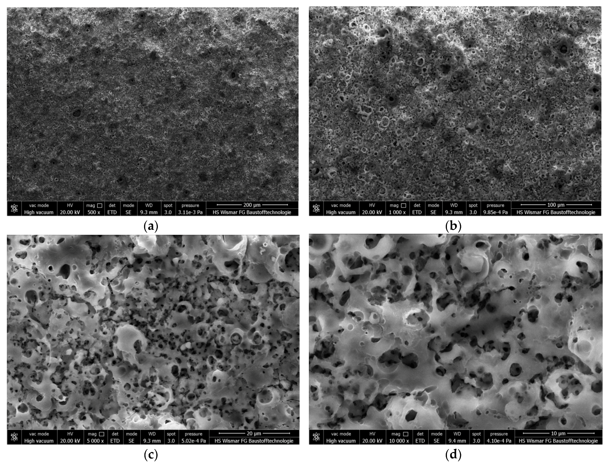
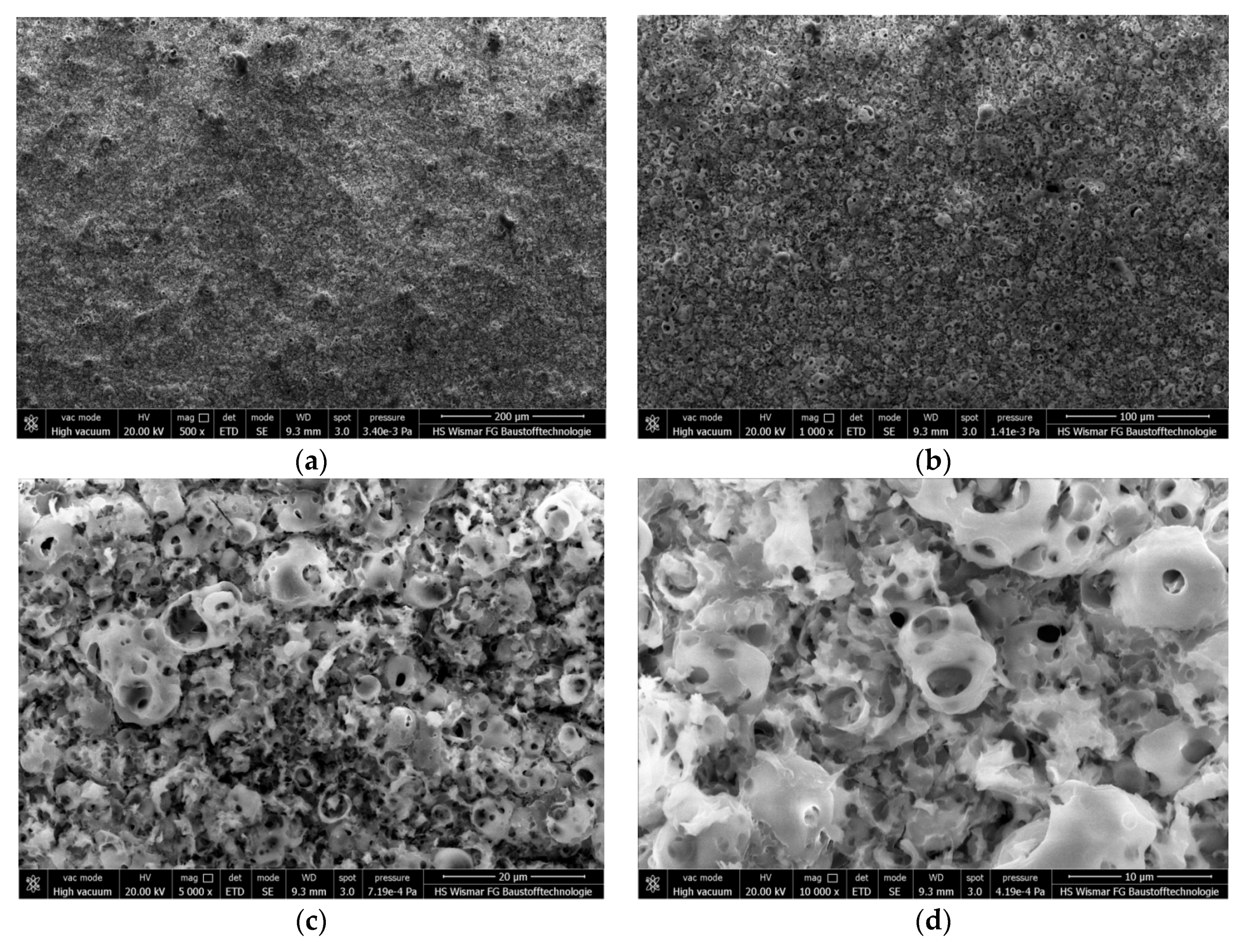
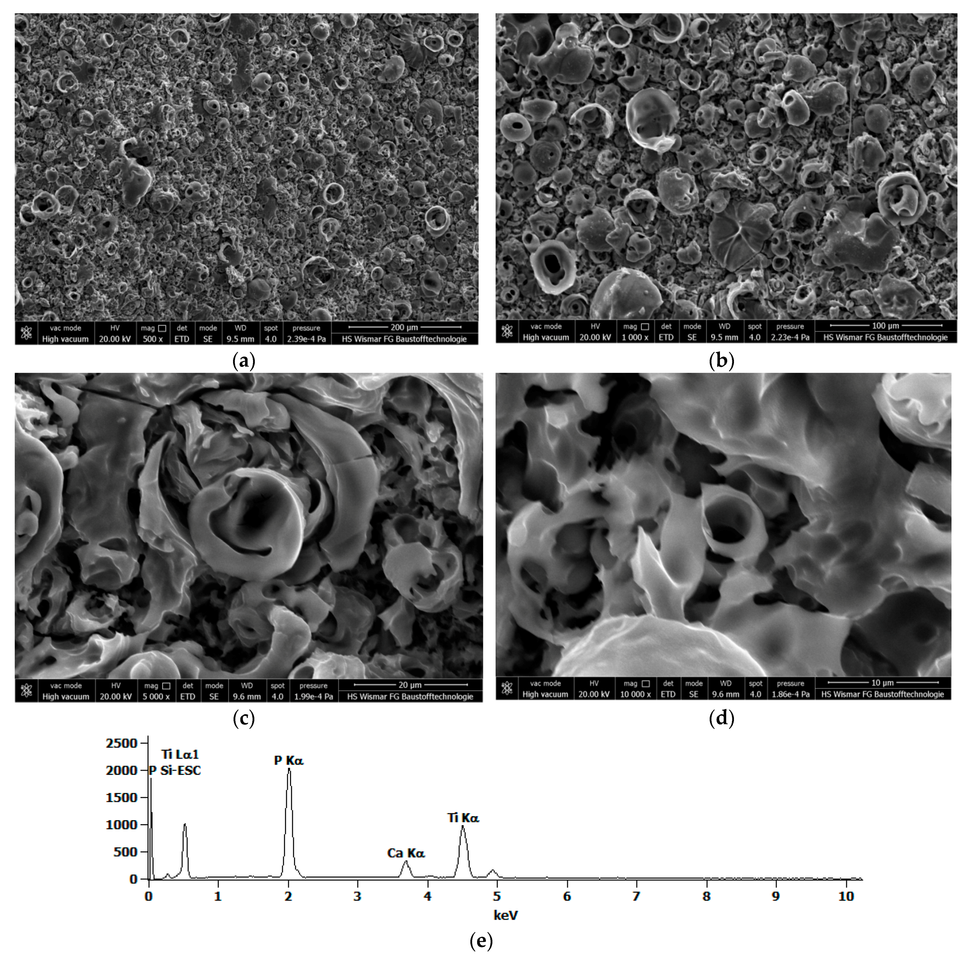
- The coating obtained in the electrolyte with 10 g/L of calcium nitrate tetrahydrate in it at 450 ± 46 V with a pulsation of 300 Hz is not porous, whereas the coatings formed in the solutions with 300 and 600 g/L Ca(NO3)2·4H2O are porous.
- (2)
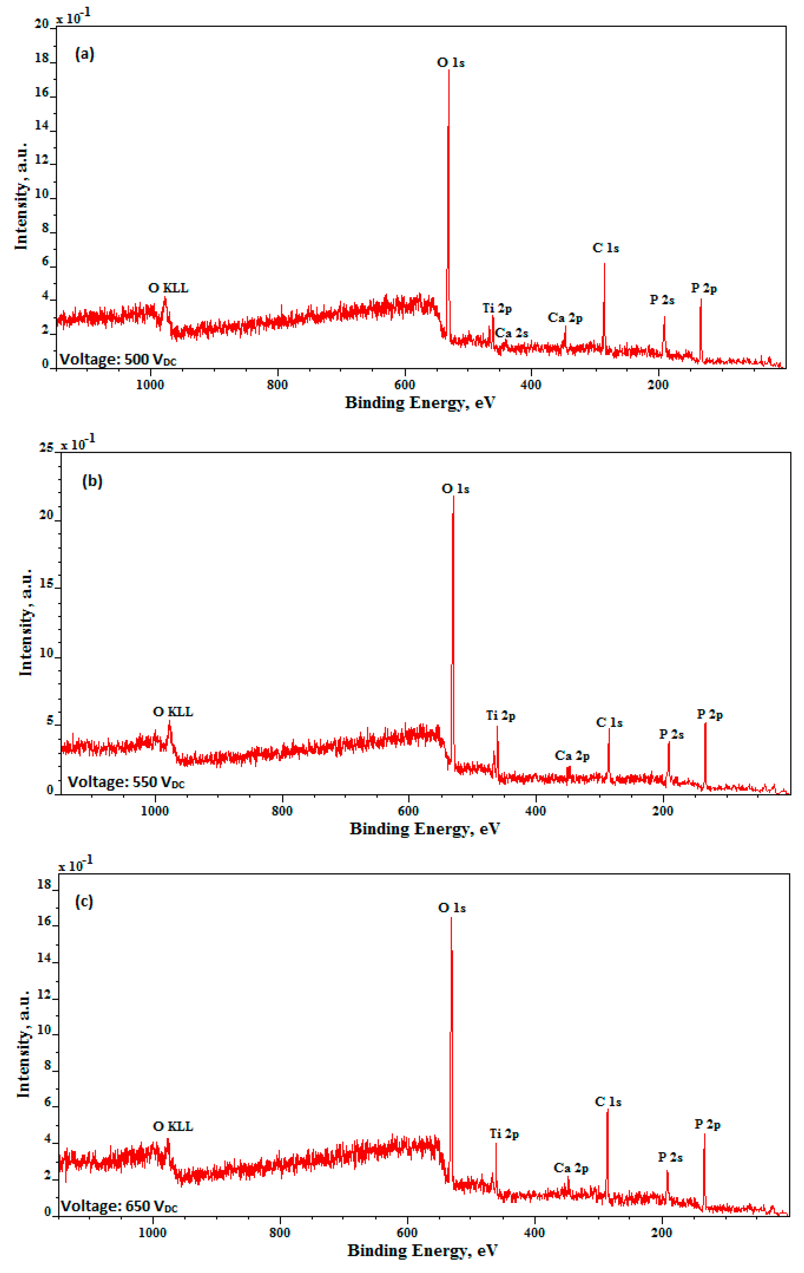
- The Ca/P ratio of the coatings, obtained by using a commercial DC power supply without pulsation, at 450 V, in an electrolyte containing 500 g/L of Ca(NO3)2·4H2O, is equal to 0.18 ± 0.01, which is slightly higher than that calculated for the coating formed at 450 ± 46 V with a pulsation of 300 Hz (0.15 ± 0.01).
- (3)
- In the PEO coatings, three different sub-layers may be distinguished, i.e., the first with open pores, the second that is semi-porous and enriched in calcium, and the third, a transition sub-layer.
- (4)
- The higher the amount of calcium nitrate tetrahydrate dissolved in an electrolyte, the thicker the second and third sub-layers become.
- (5)
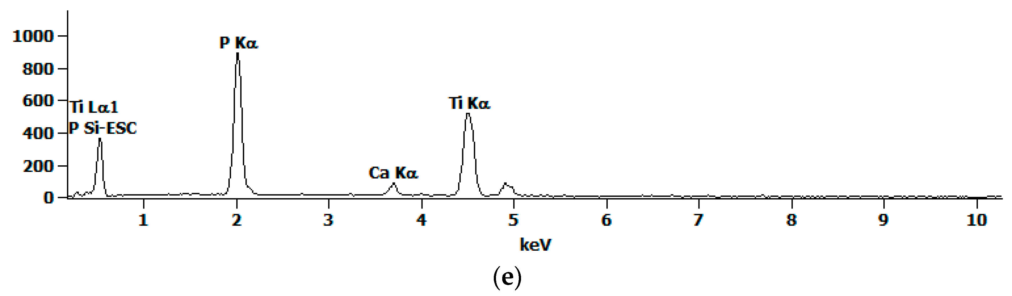
- The top surface of the PEO coatings consists of titanium (Ti4+), calcium (Ca2+), as well as phosphorus and oxygen (PO43− and/or HPO42− and/or H2PO4−, and/or P2O74−).
Acknowledgments
Author Contributions
Conflicts of Interest
References
- Aliasghari, S. Plasma Electrolytic Oxidation of Titanium. Ph.D. Thesis, The University of Manchester, Manchester, UK, 2014; p. 223. [Google Scholar]
- Simka, W.; Sadowski, A.; Warczak, M.; Iwaniak, A.; Dercz, G.; Michalska, J.; Maciej, A. Modification of Titanium Oxide Layer by Calcium and Phosphorus. Electrochim. Acta 2011, 56, 8962–8968. [Google Scholar] [CrossRef]
- Rokosz, K.; Hryniewicz, T.; Raaen, S.; Malorny, W. Fabrication and Characterisation of Porous Coatings Obtained by Plasma Electrolytic Oxidation. J. Mech. Energy Eng. 2017, 1, 23–30. [Google Scholar]
- Puz’, A.V.; Khlusov, I.A.; Opra, D.P. Functional Coatings Formed on the Titanium and Magnesium Alloys as Implant Materials by Plasma Electrolytic Oxidation Technology: Fundamental Principles and Synthesis Conditions. Corros. Rev. 2016, 34, 65–83. [Google Scholar]
- Hryniewicz, T.; Rokosz, K.; Zschommler Sandim, H.R. SEM/EDX and XPS Studies of Niobium after Electropolishing. Appl. Surf. Sci. 2012, 263, 357–361. [Google Scholar] [CrossRef]
- Rokicki, R.; Hryniewicz, T.; Konarski, P.; Rokosz, K. The Alternative, Novel Technology for Improvement of Surface Finish of SRF Niobium Cavities. World Sci. News 2017, 74, 152–163. [Google Scholar]
- Rokosz, K.; Hryniewicz, T. Characteristics of Porous and Biocompatible Coatings Obtained on Niobium and Titanium-Niobium-Zirconium (TNZ) Alloy by Plasma Electrolytic Oxidation. Mechanik 2015, 12, 15–18. [Google Scholar] [CrossRef]
- Rokosz, K.; Hryniewicz, T.; Matysek, D.; Dudek, Ł.; Valiček, J.; Harničarova, M.; Kušnerova, M.; Zschommler Sandim, H.R. SEM and EDS Analysis of Niobium Surface after Plasma Electrolytic Oxidation in Concentrated Phosphoric Acid within Copper Nitrate. In Proceedings of the 25th Anniversary International Conference on Metallurgy and Materials (METAL 2016), Brno, Czech Republic, 25–27 May 2016; pp. 1157–1162. [Google Scholar]
- Rokosz, K.; Hryniewicz, T. Comparative SEM and EDX Analysis of Surface Coatings Created on Niobium and Titanium Alloys after Plasma Electrolytic Oxidation (PEO). Teh. Vjesn. Tech. Gaz. 2017, 24, 465–472. [Google Scholar]
- Rokosz, K.; Hryniewicz, T.; Chapon, P.; Raaen, S.; Zschommler Sandim, H.R. XPS and GDOES Characterisation of Porous Coating Enriched with Copper and Calcium Obtained on Tantalum via Plasma Electrolytic Oxidation. J. Spectr. 2016. [Google Scholar] [CrossRef]
- Petković, M.; Stojadinović, S.; Vasilić, R.; Belča, I.; Kasalica, B.; Zeković, L. Plasma Electrolytic Oxidation of Tantalum. Serb. J. Electr. Eng. 2012, 9, 81–94. [Google Scholar] [CrossRef]
- Sowa, M.; Kazek-Kęsik, A.; Socha, R.P.; Dercz, G.; Michalska, J.; Simka, W. Modification of Tantalum Surface via Plasma Electrolytic Oxidation in Silicate Solutions. Electrochim. Acta 2013, 114, 627–636. [Google Scholar] [CrossRef]
- Petković, M.; Stojadinović, S.; Vasilić, R.; Zeković, Lj. Characterization of Oxide Coatings Formed on Tantalum by Plasma Electrolytic Oxidation in 12-tungstosilicic Acid. Appl. Surf. Sci. 2011, 257, 10590–10594. [Google Scholar] [CrossRef]
- Stojadinović, S.; Jovović, J.; Petković, M.; Vasilić, R. Spectroscopic and Real-time Imaging Investigation of Tantalum Plasma Electrolytic Oxidation (PEO). Surf. Coat. Technol. 2011, 205, 5406–5413. [Google Scholar] [CrossRef]
- Goularte, M.A.P.C.C.; Barbosa, G.F.; da Cruz, N.C.; Hirakata, L.M. Achieving Surface Chemical and Morphologic Alterations on Tantalum by Plasma Electrolytic Oxidation. Int. J. Implant Dent. 2016, 2, 1–12. [Google Scholar] [CrossRef] [PubMed]
- Krząkala, A.; Młynski, J.; Dercz, G.; Michalska, J.; Maciej, A.; Nieużyla, L.; Simka, W. Modification of Ti-6Al-4V Alloy Surface by EPD-PEO Process in ZrSiO4 Suspension. Arch. Metall. Mater. 2014, 59, 199–204. [Google Scholar] [CrossRef]
- Rokicki, R.; Hryniewicz, T. Nitinol Surface Finishing by Magnetoelectropolishing. Trans. Inst. Met. Finish. 2008, 86, 280–285. [Google Scholar] [CrossRef]
- Simka, W.; Nawrat, G.; Chlode, J.; Maciej, A.; Winiarski, A.; Szade, J.; Radwański, K.; Gazdowicz, J. Electropolishing and Anodic Passivation of Ti6Al7Nb Alloy. Przem. Chem. 2011, 90, 84–90. [Google Scholar]
- Rokosz, K.; Hryniewicz, T.; Raaen, S.; Chapon, P. Investigation of Porous Coatings Obtained on Ti-Nb-Zr-Sn Alloy Biomaterial by Plasma Electrolytic Oxidation: Characterisation and Modelling. Int. J. Adv. Manuf. Technol. 2016, 87, 3497–3512. [Google Scholar] [CrossRef]
- Rokosz, K.; Hryniewicz, T.; Raaen, S. SEM, EDS and XPS Analysis of Nanostructured Coating Obtained on NiTi Biomaterial Alloy by Plasma Electrolytic Oxidation (PEO). Teh. Vjesn. Tech. Gaz. 2017, 24, 193–198. [Google Scholar]
- Rokosz, K.; Hryniewicz, T.; Raaen, S. Development of Plasma Electrolytic Oxidation for Improved Ti6Al4V Biomaterial Surface Properties. Int. J. Adv. Manuf. Technol. 2016, 85, 2425–2437. [Google Scholar] [CrossRef]
- Rokosz, K.; Hryniewicz, T.; Raaen, S.; Chapon, P. Development of Copper-enriched Porous Coatings on Ternary Ti-Nb-Zr Alloy by Plasma Electrolytic Oxidation. Int. J. Adv. Manuf. Technol. 2017, 89, 2953–2965. [Google Scholar] [CrossRef]
- Hryniewicz, T.; Rokosz, K.; Rokicki, R.; Prima, F. Nanoindentation and XPS Studies of Titanium TNZ Alloy after Electrochemical Polishing in a Magnetic Field. Materials 2015, 8, 205–215. [Google Scholar] [CrossRef] [PubMed]
- Hryniewicz, T.; Rokosz, K.; Valiček, J.; Rokicki, R. Effect of Magnetoelectropolishing on Nanohardness and Young’s Modulus of Titanium Biomaterial. Mater. Lett. 2012, 83, 69–72. [Google Scholar] [CrossRef]
- Krupa, D.; Baszkiewicz, J.; Zdunek, J.; Sobczak, J.W.; Lisowski, W.; Smolik, J.; Słomka, Z. Effect of Plasma Electrolytic Oxidation in the Solutions Containing Ca, P, Si, Na on the Properties of Titanium. J. Biomed. Mater. Res. B Appl. Biomater. 2012, 100, 2156–2166. [Google Scholar] [CrossRef] [PubMed]
- Yang, W.; Li, Q.; Liu, C.; Liang, J.; Peng, Z.; Liu, B. A Comparative Study of Characterisation of Plasma Electrolytic Oxidation Coatings on Carbon Steel Prepared from Aluminate and Silicate Electrolytes. Surf. Eng. 2017, 1–9. [Google Scholar] [CrossRef]
- Fei, C.; Hai, Z.; Chen, C.; Yangjian, X. Study on the Tribological Performance of Ceramic Coatings on Titanium Alloy Surfaces Obtained through Microarc Oxidation. Prog. Org. Coat. 2009, 64, 264–267. [Google Scholar] [CrossRef]
- Hryniewicz, T.; Rokicki, R.; Rokosz, K. Co-Cr Alloy Corrosion Behaviour after Electropolishing and “Magnetoelectropolishing” Treatments. Surf. Coat. Technol. 2008, 62, 3073–3076. [Google Scholar] [CrossRef]
- Hryniewicz, T.; Rokicki, R.; Rokosz, K. Corrosion and Surface Characterization of Titanium Biomaterial after Magnetoelectropolishing. Surf. Coat. Technol. 2008, 203, 1508–1515. [Google Scholar] [CrossRef]
- Rokosz, K.; Hryniewicz, T. Effect of Magnetic Field on the Pitting Corrosion of Austenitic Steel Type AISI 304. Ochr. Przed Koroz. 2011, 54, 487–491. [Google Scholar]
- Hryniewicz, T.; Rokosz, K. Corrosion Resistance of Magnetoelectropolished AISI 316L SS Biomaterial. Anti-Corros. Methods Mater. 2014, 61, 57–64. [Google Scholar] [CrossRef]
- Echeverry-Rendón, M.; Galvis, O.; Giraldo, D.Q.; Pavón, J.; López-Lacomba, J.L.; Jiménez-Piqué, E.; Anglada, M.; Robledo, S.M.; Castaño, J.G.; Echeverría, F. Osseointegration Improvement by Plasma Electrolytic Oxidation of Modified Titanium Alloys Surfaces. J. Mater. Sci. Mater. Med. 2015, 26, 1–18. [Google Scholar] [CrossRef] [PubMed] [Green Version]
- Rokicki, R.; Haider, W.; Hryniewicz, T. Influence of Sodium Hypochlorite Treatment of Electropolished and Magnetoelectropolished Nitinol Surfaces on Adhesion and Proliferation of MC3T3 Pre-osteoblast Cells. J. Mater. Sci. Mater. Med. 2012, 23, 2127–2139. [Google Scholar] [CrossRef] [PubMed]
- Sowa, M.; Piotrowska, M.; Widziołek, M.; Dercz, G.; Tylko, G.; Gorewoda, T.; Osyczka, A.M.; Simka, W. Bioactivity of Coatings Formed on Ti-13Nb-13Zr Alloy Using Plasma Electrolytic Oxidation. Mater. Sci. Eng. C Mater. Biol. Appl. 2015, 49, 159–173. [Google Scholar] [CrossRef] [PubMed]
- Hryniewicz, T. Concept of Microsmoothing in the Electropolishing Process. Surf. Coat. Technol. 1994, 64, 75–80. [Google Scholar] [CrossRef]
- Hryniewicz, T.; Hryniewicz, Z. On the Solution of Equation of Diffusion in Electropolishing. J. Electrochem. Soc. 1989, 136, 3767–3769. [Google Scholar] [CrossRef]
- Rokicki, R.; Hryniewicz, T. Enhanced Oxidation-Dissolution Theory of Electropolishing. Trans. Inst. Met. Finish. 2012, 90, 188–196. [Google Scholar] [CrossRef]
- Hryniewicz, T.; Rokosz, K. Analysis of XPS Results of AISI 316L SS Electropolished and Magnetoelectropolished at Varying Conditions. Surf. Coat. Technol. 2010, 204, 2583–2592. [Google Scholar] [CrossRef]
- Rokosz, K. Electrochemical Polishing in the Magnetic Field; Koszalin University of Technology Publishing House: Koszalin, Poland, 2012. (In Polish) [Google Scholar]
- Rokosz, K.; Hryniewicz, T.; Raaen, S. XPS Analysis of Nanolayer Formed on AISI 304L after High-Voltage Electropolishing (HVEP). Teh. Vjesn. Tech. Gaz. 2017, 24, 321–326. [Google Scholar]
- Rokicki, R.; Hryniewicz, T.; Rokosz, K. Modifying Metallic Implants by Magnetoelectropolishing. Med. Device Diagn. Ind. 2008, 30, 102–111. [Google Scholar]
- Hryniewicz, T.; Rokicki, R.; Rokosz, K. Magnetoelectropolishing for Metal Surface Modification. Trans. Inst. Met. Finish. 2007, 85, 325–332. [Google Scholar] [CrossRef]
- Hryniewicz, T.; Rokosz, K. Polarization Characteristics of Magnetoelectropolishing Stainless Steels. Mater. Chem. Phys. 2010, 122, 169–174. [Google Scholar] [CrossRef]
- Rokosz, K.; Hryniewicz, T. XPS Measurements of LDX 2101 Duplex Steel Surface after Magnetoelectropolishing. Int. J. Mater. Res. 2013, 104, 1223–1232. [Google Scholar] [CrossRef]
- Rokosz, K.; Hryniewicz, T.; Simon, F.; Rzadkiewicz, S. Comparative XPS Analysis of Passive Layers Composition Formed on AISI 304 L SS after Standard and High-Current Density Electropolishing. Surf. Interface Anal. 2015, 47, 87–92. [Google Scholar] [CrossRef]
- Rokosz, K.; Lahtinen, J.; Hryniewicz, T.; Rzadkiewicz, S. XPS Depth Profiling Analysis of Passive Surface Layers Formed on Austenitic AISI 304L and AISI 316L SS after High-Current-Density Electropolishing. Surf. Coat. Technol. 2015, 276, 516–520. [Google Scholar] [CrossRef]
- Rokosz, K.; Hryniewicz, T.; Simon, F.; Rzadkiewicz, S. Comparative XPS Analyses of Passive Layers Composition Formed on Duplex 2205 SS after Standard and High-Current-Density Electropolishing. Teh. Vjesn. Tech. Gaz. 2016, 23, 731–735. [Google Scholar]
- Hryniewicz, T.; Rokosz, K. Investigation of Selected Surface Properties of AISI 316L SS after Magnetoelectropolishing. Mater. Chem. Phys. 2010, 123, 47–55. [Google Scholar] [CrossRef]
- Rokosz, K.; Hryniewicz, T.; Raaen, S. Cr/Fe Ratio by XPS Spectra of Magnetoelectropolished AISI 316L SS Fitted by Gaussian-Lorentzian Shape Lines. Teh. Vjesn. Tech. Gaz. 2014, 21, 533–538. [Google Scholar]
- Rokosz, K.; Hryniewicz, T.; Raaen, S. Characterization of Passive Film Formed on AISI 316L Stainless Steel after Magnetoelectropolishing in a Broad Range of Polarization Parameters. Steel Res. Int. 2012, 83, 910–918. [Google Scholar] [CrossRef]
- Rokosz, K.; Hryniewicz, T. XPS Analysis of Nanolayers Obtained on AISI 316L SS after Magnetoelectropolishing. World Sci. News 2016, 57, 232–248. [Google Scholar]
- Rokosz, K.; Hryniewicz, T.; Chapon, P.; Dudek, Ł. A New Approach to Porous PEO Coating Sub-layers Determination on the basis of GDOES Signals. World Sci. News 2016, 57, 289–299. [Google Scholar]
- Hryniewicz, T.; Konarski, P.; Rokicki, R.; Valiček, J. SIMS Studies of Titanium Biomaterial Hydrogenation after Magnetoelectropolishing. Surf. Coat. Technol. 2012, 206, 4027–4031. [Google Scholar] [CrossRef]
- Hryniewicz, T.; Konarski, P.; Rokicki, R.; Valiček, J. SIMS Analysis of Hydrogen Content in Near Surface Layers of AISI 316L SS after Electrolytic Polishing under Different Conditions. Surf. Coat. Technol. 2011, 205, 4228–4236. [Google Scholar] [CrossRef]
- Rokosz, K.; Hryniewicz, T.; Pietrzak, K. Synthesis and characterisation of porous, calcium enriched coatings formed on Titanium via Plasma Electrolytic Oxidation. World Sci. News 2017, 83, 29–44. [Google Scholar]
- Vallet-Regí, M.; Arcos Navarrete, D.A. Nanoceramics in Clinical Use From Materials to Applications, 2nd ed.; The Royal Society of Chemistry, Thomas Graham House, RSC Nanoscience & Nanotechnology No. 39: Cambridge, UK, 2016; p. 331. ISBN 978-1-78262-104-1. [Google Scholar]
- Heimann, R.B.; Lehmann, H.D. Bioceramic Coatings for Medical Implants Trends and Techniques; Wiley-VCH Verlag GmbH & Co.: Weinheim, Germany, 2015; p. 467. ISBN 978-3-527-33743-9. [Google Scholar]
- Hempel, F.; Finke, B.; Zietz, C.; Bader, R.; Weltmann, K.-D.; Polak, M. Antimicrobial Surface Modification of Titanium Substrates by Means of Plasma Immersion Ion Implantation and Deposition of Copper. Surf. Coat. Technol. 2014, 256, 52–58. [Google Scholar] [CrossRef]
- Rokosz, K.; Hryniewicz, T.; Dudek, Ł.; Matysek, D.; Valiček, J.; Harničarova, M. SEM and EDS Analysis of Surface Layer Formed on Titanium After Plasma Electrolytic Oxidation in H3PO4 with the Addition of Cu(NO3)2. J. Nanosci. Nanotechnol. 2016, 16, 7814–7817. [Google Scholar] [CrossRef]
- Rokosz, K.; Hryniewicz, T.; Dalibor, M.; Raaen, S.; Valiček, J.; Dudek, Ł.; Harničarova, M. SEM, EDS and XPS Analysis of the Coatings Obtained on Titanium after Plasma Electrolytic Oxidation in Electrolytes Containing Copper Nitrate. Materials 2016, 9, 318. [Google Scholar] [CrossRef] [PubMed]
- Rokosz, K.; Hryniewicz, T.; Raaen, S.; Chapon, P.; Dudek, Ł. GDOES, XPS and SEM with EDS Analysis of Porous Coatings Obtained on Titanium after Plasma Electrolytic Oxidation. Surf. Interface Anal. 2016, 49, 303–315. [Google Scholar] [CrossRef]
- Rokosz, K.; Hryniewicz, T.; Malorny, W. Characterisation of Porous Coatings Obtained on Materials by Plasma Electrolytc Oxidation. Mater. Sci. Forum 2016, 862, 86–95. [Google Scholar] [CrossRef]
- Jelinek, M.; Kocourek, T.; Remsa, J.; Weiserová, M.; Jurek, K.; Mikšovský, J.; Strnad, J.; Galandáková, A.; Ulrichová, J. Antibacterial, Cytotoxicity and Physical Properties of Laser—Silver Doped Hydroxyapatite Layers. Mater. Sci. Eng. C 2013, 33, 1242–1246. [Google Scholar] [CrossRef] [PubMed]
- Mishra, G.; Dash, B.; Pandey, S.; Mohanty, P.P. Antibacterial Actions of Silver Nanoparticles Incorporated Zn–Al Layered Double Hydroxide and its Spinel. J. Environ. Chem. Eng. 2013, 1, 1124–1130. [Google Scholar] [CrossRef]
- Rajendran, A.; Pattanayak, D.K. Silver Incorporated Antibacterial, Cell Compatible and Bioactive Titania Layer on Ti Metal for Biomedical Applications. RSC Adv. 2014, 106, 61444–61455. [Google Scholar] [CrossRef]
- Trujillo, N.A.; Oldinski, R.A.; Ma, H.; Bryers, J.D.; Williams, J.D.; Popat, K.C. Antibacterial Effects of Silver-Doped Hydroxyapatite Thin Films Sputter Deposited on Titanium. Mater. Sci. Eng. C 2012, 32, 2135–2144. [Google Scholar] [CrossRef]
- Valiček, J.; Drzik, M.; Hryniewicz, T.; Harničarova, M.; Rokosz, K.; Kušnerova, M.; Barcova, K.; Brazina, D. Noncontact Method for Surface Roughness Measurement after Machining. Meas. Sci. Rev. 2012, 12, 184–188. [Google Scholar] [CrossRef]
- Kušnerova, M.; Valiček, J.; Harničarova, M.; Hryniewicz, T.; Rokosz, K.; Palkova, Z.; Vaclavik, V.; Repka, M.; Bendova, M. A Proposal for Simplifying the Method of Evaluation of Uncertainties in Measurement Results. Meas. Sci. Rev. 2013, 13, 1–6. [Google Scholar] [CrossRef]
- Teker, D.; Muhaffel, F.; Menekse, M.; Karaguler, N.G.; Baydogan, M.; Cimenoglu, H. Characteristics of Multi-Layer Coating Formed on Commercially Pure Titanium for Biomedical Applications. Mater. Sci. Eng. C 2015, 48, 579–585. [Google Scholar] [CrossRef] [PubMed]
- Dzhurinskiy, D.; Gao, Y.; Yeung, W.-K.; Strumban, E.; Leshchinsky, V.; Chu, P.-J.; Matthews, A.; Yerokhin, A.; Maev, R.G. Characterization and Corrosion Evaluation of TiO2:n-HA Coatings on Titanium Alloy Formed by Plasma Electrolytic Oxidation. Surf. Coat. Technol. 2015, 269, 258–265. [Google Scholar] [CrossRef]
- Krupa, D.; Baszkiewicz, J.; Zdunek, J.; Smolik, J.; Słomka, J.; Sobczak, J.W. Characterization of the Surface Layers Formed on Titanium by Plasma Electrolytic Oxidation. Surf. Coat. Technol. 2010, 205, 1743–1749. [Google Scholar] [CrossRef]
- Wang, H.-Y.; Zhu, R.-F.; Lu, Y.-P.; Xiao, G.-Y.; Zhao, X.-C.; He, K.; Yuan, Y.F.; Ying, L.; Ma, X.-N. Preparation and Properties of Plasma Electrolytic Oxidation Coating on Sandblasted Pure Titanium by a Combination Treatment. Mater. Sci. Eng. C 2014, 42, 657–664. [Google Scholar] [CrossRef] [PubMed]
- Kazek-Kęsik, A.; Krok-Borkowicz, M.; Pamuła, E.; Simka, W. Electrochemical and Biological Characterization of Coatings Formed on Ti–15Mo Alloy by Plasma Electrolytic Oxidation. Mater. Sci. Eng. C 2014, 43, 172–181. [Google Scholar] [CrossRef] [PubMed]
- Nelis, T.; Payling, R. Practical Guide to Glow Discharge Optical Emission Spectroscopy; Barnett, N.W., Ed.; RSC Analytical Spectroscopy Monographs; Royal Society of Chemistry: Cambridge, UK, 2002. [Google Scholar]
- Pulsed RF Glow Discharge Optical Emission Spectrometry—Ultra Fast Elemental Depth Profiling, HORIBA Scientific, Printed in France—©HORIBA Jobin Yvon: 2014, p. 7. Available online: http://www.horiba.com/scientific/products/atomic-emission-spectroscopy/glow-discharge/ (accessed on 27 July 2017).
- Gaiaschi, S.; Richard, S.; Chapon, P.; Acher, O. Real-time measurement in glow discharge optical emission spectrometry via differential interferometric profiling. J. Anal. Atom. Spectrom. 2017, 32, 1798–1804. [Google Scholar] [CrossRef]
- Casa Software Ltd. CasaXPS: Processing Software for XPS, AES, SIMS and More. 2009. Available online: http://www.casaxps.com (accessed on 31 July 2007).
- Wagner, C.D.; Naumkin, A.V.; Kraut-Vass, A.; Allison, J.W.; Powell, C.J.; Rumble, J.R., Jr. NIST Standard Reference Database 20, Version 3.4. 2003. Available online: http://srdata.nist.gov/xps (accessed on 31 July 2007).


© 2017 by the authors. Licensee MDPI, Basel, Switzerland. This article is an open access article distributed under the terms and conditions of the Creative Commons Attribution (CC BY) license (http://creativecommons.org/licenses/by/4.0/).
Share and Cite
Rokosz, K.; Hryniewicz, T.; Gaiaschi, S.; Chapon, P.; Raaen, S.; Pietrzak, K.; Malorny, W. Characterisation of Calcium- and Phosphorus-Enriched Porous Coatings on CP Titanium Grade 2 Fabricated by Plasma Electrolytic Oxidation. Metals 2017, 7, 354. https://doi.org/10.3390/met7090354
Rokosz K, Hryniewicz T, Gaiaschi S, Chapon P, Raaen S, Pietrzak K, Malorny W. Characterisation of Calcium- and Phosphorus-Enriched Porous Coatings on CP Titanium Grade 2 Fabricated by Plasma Electrolytic Oxidation. Metals. 2017; 7(9):354. https://doi.org/10.3390/met7090354
Chicago/Turabian StyleRokosz, Krzysztof, Tadeusz Hryniewicz, Sofia Gaiaschi, Patrick Chapon, Steinar Raaen, Kornel Pietrzak, and Winfried Malorny. 2017. "Characterisation of Calcium- and Phosphorus-Enriched Porous Coatings on CP Titanium Grade 2 Fabricated by Plasma Electrolytic Oxidation" Metals 7, no. 9: 354. https://doi.org/10.3390/met7090354