Article

Mechanical Characterization of Composite Coatings Formed by Reactive Detonation Spraying of Titanium

1
College of Physics, Jilin University, Changchun 130022, China
2
Institute of Strength Physics and Materials Science SB RAS, Tomsk 634055, Russia
3
Department of Materials Science in Mechanical Engineering, National Research Tomsk Polytechnic University, Tomsk 634050, Russia
4
Laboratory of Detonation Flows, Lavrentyev Institute of Hydrodynamics SB RAS, Novosibirsk 630090, Russia
5
Department of Mechanical Engineering and Technologies, Novosibirsk State Technical University, Novosibirsk 630073, Russia
6
Department of Mechanical and Industrial Engineering, Norwegian University of Science and Technology, 7491 Trondheim, Norway
*
Author to whom correspondence should be addressed.
Metals 2017, 7(9), 355; https://doi.org/10.3390/met7090355
Submission received: 18 August 2017 / Revised: 5 September 2017 / Accepted: 5 September 2017 / Published: 8 September 2017

Abstract

:
The structure and mechanical properties of the coatings formed by reactive detonation spraying of titanium in a wide range of spraying conditions were studied. The variable deposition parameters were the nature of the carrier gas, the spraying distance, the O2/C2H2 ratio, and the volume of the explosive mixture. The phase composition of the coatings and the influence of the spraying parameters on the mechanical properties of the coatings were investigated. In addition, nanohardness of the individual phases contained in the coatings was evaluated. It was found that the composition of the strengthening phases in the coatings depends on the O2/C2H2 ratio and the nature of the carrier gas. Detonation spraying conditions ensuring the formation of composite coatings with a set of improved mechanical properties are discussed. The strength of the coatings was determined through the microhardness measurements and local characterization of the phases via nanoindentation. Three-point bending tests were employed in order to evaluate the crack resistance of the coatings. The strengthening mechanisms of the coatings by oxide or carbonitride phases were discussed.

Graphical Abstract

1. Introduction

At present, several coating deposition methods are known and widely used in the industry. The choice of a particular method is dictated by a combination of factors, such as the level of loading and operating conditions, the shape, size and geometry of machine parts to be coated, the required thickness of the coating, the necessity for mechanical post-processing, the requirements for adhesive and cohesive strength and the cost of the final product.
Thermal spraying is widely used for surface strengthening and restoration. The variations of thermal spraying are plasma spraying, flame spraying, high-velocity oxy-fuel spraying (HVOF), cold gas-dynamic spraying and detonation spraying. Thermal spraying is used to deposit high-strength materials [1] and multicomponent coatings reinforced with finely dispersed inclusions, which ensure high coating performance [2,3]. In order to form coatings containing intermetallic phases with high adhesion strength and corrosion resistance, vacuum spraying [1,2,4] is employed or deposition is carried out in an inert gas atmosphere [5].
The sprayed metallic particles can chemically react with gases contained in the spraying atmosphere, which leads to the formation of finely dispersed ceramic phases in the coatings [4,6,7].
A widespread technique for producing dispersion-strengthened coatings is the formation of oxide inclusions in metal matrices. This is achieved through oxidation of the molten particles when spraying is carried out in air. In this case, atmospheric plasma spraying can be efficiently employed [8]. A substantial drawback of this method is the porosity of the coatings and the non-uniformity of their structure.
One of the efficient technologies for restoration, repair and strengthening of machine parts is cold gas-dynamic spraying [9,10]. It is based on the layer-by-layer formation of coatings at supersonic flow velocities of the carrier gas and is associated with minimal heating of the sprayed material. The cohesive strength is, therefore, provided thanks to the high kinetic energy of the particles upon impact. This substantially reduces the probability of oxidation and eliminates the need for dynamic vacuum or an inert gas atmosphere. By selecting the optimal gas flow rate and the temperature of the gas, multicomponent coatings with a set of required physical and mechanical properties can be fabricated [10]. In addition to spraying of the powder mixtures, a unique combination of coating properties can be achieved through the deposition of alternating layers of different compositions [11].
In the framework of this classification, a technique of coating deposition from powder mixtures using concentrated pulsed energy flows has to be mentioned. This technique allows forming layers that possess low porosity, high adhesion to the substrate, and submicro- or nanocrystalline structures [12]. The drawback of this method is poor control of the structure and geometry of the coatings.
Currently, detonation spraying and HVOF are the most efficient methods of depositing coatings that can protect machine parts from erosion, corrosion and different types of wear [13,14]. Low porosity of the coatings is achieved due to high velocities of the particles [5]. The method can also be applied for metallization of ceramics and periodic restoration of the worn machine parts [15,16,17].
In Ref. [18], the application of the HVOF technique to deposit WC-Co coatings is compared with the ecologically unfriendly chrome plating, which has been used in the industry for a long time. A comparative analysis of the structure and properties of Cu-Ni-In coatings formed by plasma and detonation sputtering onto Ti-4Al-6V substrate was performed in Ref. [19]. It was shown that the detonation-sprayed coatings show a higher adhesion, a reduced porosity and a more uniform structure than the plasma sprayed ones. The improved structural characteristics increase the fatigue life and resistance to fretting corrosion of the coatings.
The surface quality of the thermally sprayed coatings depends on the surface finish and can be improved by droplet elimination [20]. Also, machining of the thermally sprayed coatings is needed to achieve dimensional tolerances [21]. Therefore, the mechanical strength and integrity of the coatings are important not only for their functional performance, but also as guaranteeing the capability of the coatings to withstand the machining operations.
Chemical reactions involving the sprayed materials and phase transitions in the sprayed material can exert both positive and negative effects on the coating performance. TiO2 coatings formed by the HVOF technique were studied in Ref. [22]. The powder was introduced by both internal and external injection. It was shown that by varying the composition of the sprayed powder and the way of its introduction into the gas flow, it is possible to control the amount of anatase that affects the structure and photocatalytic properties of the coating.
In this paper, the structure and mechanical properties of deposits formed on titanium substrates by reactive detonation spraying of a titanium powder were investigated. The aim of the present work was to determine the effect of the coating structure on the mechanical properties of the coatings.

2. Materials and Methods

The deposition of the coatings onto titanium substrates was carried out using a computer controlled detonation spraying (CCDS2000) facility (Lavrentyev Institute of Hydrodynamics SB RAS, Novosibirsk, Russia) [23]. The substrates were sand-blasted before depositing the coating layers. Titanium (99% purity, average particle size 15 μm, “PTOM-2”, Russia) was used as a feedstock powder. The spraying distance was 10 mm or 100 mm. Air or nitrogen was used as a carrier gas. Spraying was performed using different compositions of acetylene-oxygen mixtures corresponding to O2/C2H2 molar ratios of 0.7, 1.1 and 2.5 (Table 1). The use of nitrogen as a carrier gas reduces the concentration of oxygen in the spraying atmosphere and the oxidation degree of the material. It should be kept in mind that air, when used as a carrier gas, is not the only source of oxidizing agents, as the detonation products themselves contain oxidizing species. The concentrations of oxidizing species in the detonation products depend on the O2/C2H2 ratio. The spraying frequency was 4–5 shots per second. On average, in order to obtain a coating 300 μm thick on a spot 20 mm in diameter, 60–70 shots are needed. The volume fractions of the barrel filled with an explosive mixture (explosive charge) was 30–60% of the total barrel volume. Conditions of the enhanced nitride formation were created by introducing nitrogen into the explosive mixture.
Elemental microanalysis of the coatings was carried out by Energy Dispersive Spectroscopy (EDS) using an INCA unit (Oxford instruments, Abingdon, UK) attached to a LEO EVO 50 scanning electron microscope (Zeiss, Oberkochen, Germany). The X-ray diffraction (XRD) patterns of the coatings were recorded using a D8 ADVANCE powder diffractometer (Bruker AXS, Karlsruhe, Germany).
Three test samples of the coatings were obtained for each selected set of the detonation spraying parameters (spraying regime). The detonation spraying experiments showed good reproducibility in terms of the phase composition and structure of the deposited layers. The three samples obtained as a result of three runs under the constant conditions were used for the preparation of samples for mechanical testing. Accordingly, for a mechanical characteristic, an average of three measurements is reported for each spraying regime.
In order to study the correlation between the structure and the mechanical properties of the coatings, three-point bending tests were carried out using an electromechanical testing machine Instron 5582. This loading scheme was chosen as under applied external force, the surface layer (the detonation coating) plays a major role in providing resistance to deformation and fracture. The three-point bending tests in combination with photographing the specimen lateral surface allow gaining detailed information on the deformation behavior and estimating the cracking stress σcr [24].
The stress under three-point bending was calculated with the help of Equation (1) [25]:
σ = M max W ,
where Mmax is the largest value of bending moment Equation (2) (P is bending load; l is the distance between the supports (span).
M max = P × l 4 ,
W is the resistance momentum, which for rectangular-section specimens can be calculated by Equation (3) (b is the width and h is the gauge height of the specimens).
W = b × h 2 6 .
The shear stress was calculated by Equation (4) [26]:
τ = h coat × σ delam L c ,
where hcoat is the coating thickness, σdelam is the stress, at which the coating starts to delaminate (delamination stress) and Lc is the distance between the cracks in the coating.
The interface fracture toughness (“coating shear resistance”) was determined by Equation (5) [26]:
K c = τ × ( π × L c ) 1 / 2 .
For mechanical testing, rectangular specimens 20 × 10 × 2.5 mm3 in size were prepared using electroerosion cutting. The span (the distance between the supports) was 19 mm. Since the titanium substrates possess high ductility, it was nearly impossible to fracture the specimen using the selected loading scheme. For this reason, the evaluation of the mechanical properties was carried out at a bending deflection of 2.5 mm.
Scratch tests were carried out to evaluate the adhesion strength. A Revetest-RST scratcher (CSM-Instruments, Peseux, Switzerland) was used for these measurements. The velocity of the indenter was 2 mm/min. The load was increased from 0.6 N to 200 N. The friction coefficient was calculated as an average over the entire scratch length. The depth of the scratch tracks was estimated by a white light optical interferometer NewView 6200 (Zygo, Berwyn, PA, USA).
Microhardness of the coatings Hμ was measured on the polished surface parallel to the coating/substrate interface using a PMT-3 testing machine (LOMO, St. Petersburg, Russia). The load onto the Vickers pyramid was 100 g. Local characterization of the mechanical properties of the coating phases through nanohardness measurement was carried out by nanoindentation with the help of a Nano Indenter G200 (MTS Systems Corporation, Eden Prairie, MN, USA). Nanohardness was measured on the polished cross-sections of the coatings.

3. Results and Discussion

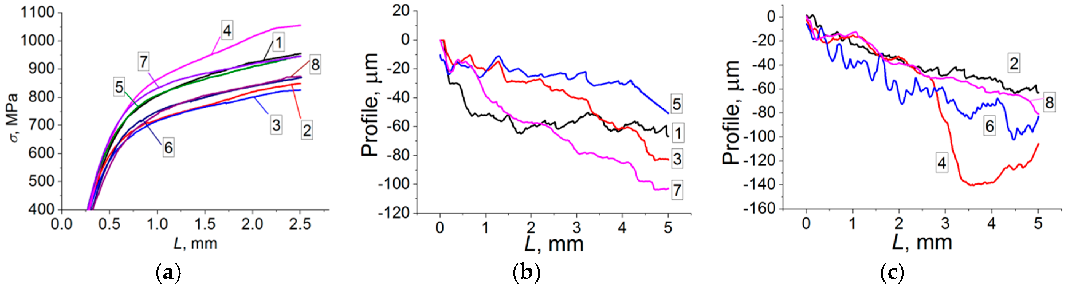
3.1. Three-Point Bending Test

The results of three-point bending tests (Figure 1a, Table 2) show that the value of the σ2.5 parameter in the specimens varies within a wide range (σ2.5 = 820–1055 MPa). However, the value of this parameter weakly correlates with the strength characteristics of the coatings, partially due to significant differences in the coating thickness. It was concluded that the shape of the three-point bending diagram does not unambiguously show the contribution of the coating to the deformation resistance of the entire coated specimen. Thus, it is necessary to measure the mechanical properties of the coatings locally.

3.2. Scratch Tests

With the help of scratch tests, a number of mechanical characteristics of the coatings were measured (Figure 1, Table 2). The values of the friction coefficient and the penetration depth of the indenter at the maximum load were determined. The obtained results correlate with the coating strength. The values of microhardness of specimens produced in regime No. 1 and No. 2 are the highest among the studied specimens (H100 = 3.7–3.84 GPa), while the friction coefficients are the lowest (μ0 ~0.41).

3.2.1. Spraying Regime 1

During the scratch test, the indenter initially quickly penetrated into the coating at 55 μm, the track length reaching 1 mm. Upon further scratching, the penetration depth increased to 67 μm.
This was probably related to an imperfect structure of the surface layer. The scratch profile oscillated due to a non-uniform structure of the coating (Figure 1b, curve 1). The coating possesses a sufficiently high bending cracking resistance (σcr = 98.4 MPa), a high bending delamination stress (σdelam = 540 MPa) and a high interface fracture toughness (Kc = 10.4 MPa·m1/2).

3.2.2. Spraying Regime 2

With increasing load, the penetration depth of the pyramid during the scratch test changed almost linearly (Figure 1c, curve 2). At the end of the test, the indenter reached a depth of 63.4 μm, which is close to the value observed during testing of specimen produced in regime No. 1. This agrees with a higher microhardness of specimen produced in regime No. 2 as compared to specimen No. 1. In addition, compared with specimen produced in regime No. 1, specimen produced in regime No. 2 possesses a higher fracture toughness, a higher interface strength, a higher bending delamination stress σdelam = 630 MPa and a higher interface fracture toughness (Kc = 12.7 MPa·m1/2, which is the maximum value among the specimens studied).

3.2.3. Spraying Regime 3

The pattern of the scratching diagram is similar to that of specimen produced in regime No. 2, while the indentation depth at the end of the profile is 83.3 μm (Figure 1b, curve 3). This correlates well with a decrease in the microhardness down to 2.68 GPa. However, this coating has a higher bending delamination stress (σdelam = 620 MPa). The interface fracture toughness is moderate (Kc = 4.8 MPa·m1/2).

3.2.4. Spraying Regime 4

The maximum indentation depth was 140.5 μm (Figure 1c, curve 4). Such a penetration depth of the indentor should be attributed to structural heterogeneity confirmed by the scratch profile at distances of 3–5 mm from the onset of scratching. The cracking stress, the bending delamination stress and interface fracture toughness are low.

3.2.5. Spraying Regime 5

The indenter penetrated smoothly into the material without any significant jumps. The maximum penetration depth was 50.7 μm (Figure 1b, curve 5). The diagram shows several peaks and zones with different rates of indenter penetration, which indicate a heterogeneous structure of the coating. This correlates well with mechanical properties—high values of cracking stresses, bending delamination, interface toughness and microhardness.

3.2.6. Spraying Regime 6

The maximum depth of the indenter penetration was 102.2 μm, while the indentation profile showed oscillations, which indicate a noticeable fraction of elastic recovery (Figure 1c, curve 6). The depth of the track increased gradually with the applied load. At a scratching distance of 4 mm, the oscillation frequency increased, which may be attributed to structural heterogeneity at the given depth. This coating possesses the lowest hardness.

3.2.7. Spraying Regime 7

The profile of the scratching diagram was close to linear shape (without pronounced oscillations), while the maximum penetration depth at the end of the track was 103.5 μm (Figure 1b, curve 7). This specimen shows the maximum cracking stress among the compositions studied (σcr = 372 MPa). The stress delamination is also very high (σdelam = 800 MPa). The interface fracture toughness is slightly higher than that of specimen No. 2 (Kc = 11.6 MPa·m1/2).

3.2.8. Spraying Regime 8

In terms of the shape of the indentation diagram and parameters of the test, this composition is similar to specimen produced in regime No. 7 (Figure 1c, curve 8). However, the bending cracking stress is substantially lower (σcr = 33 MPa).

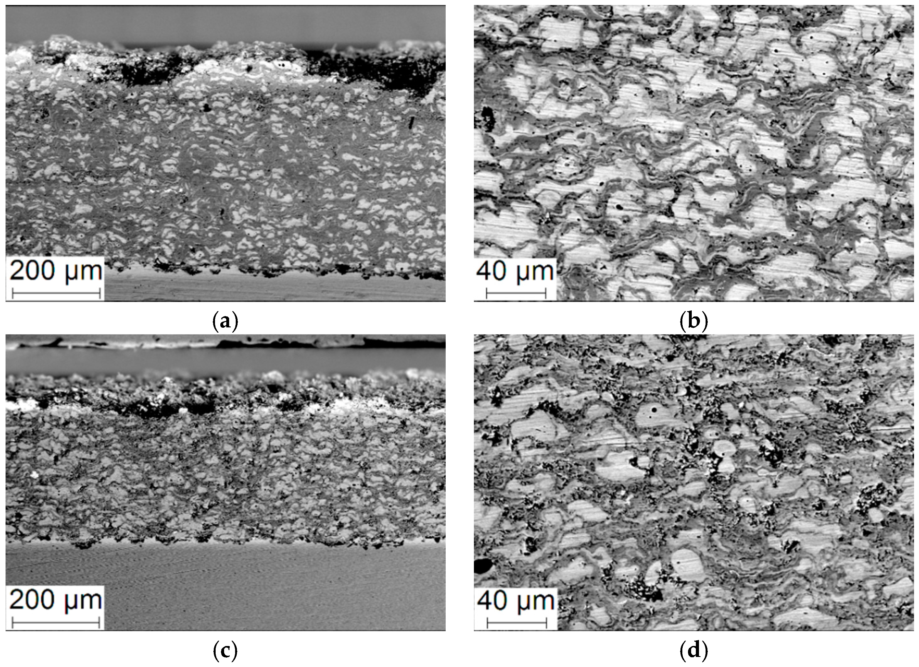
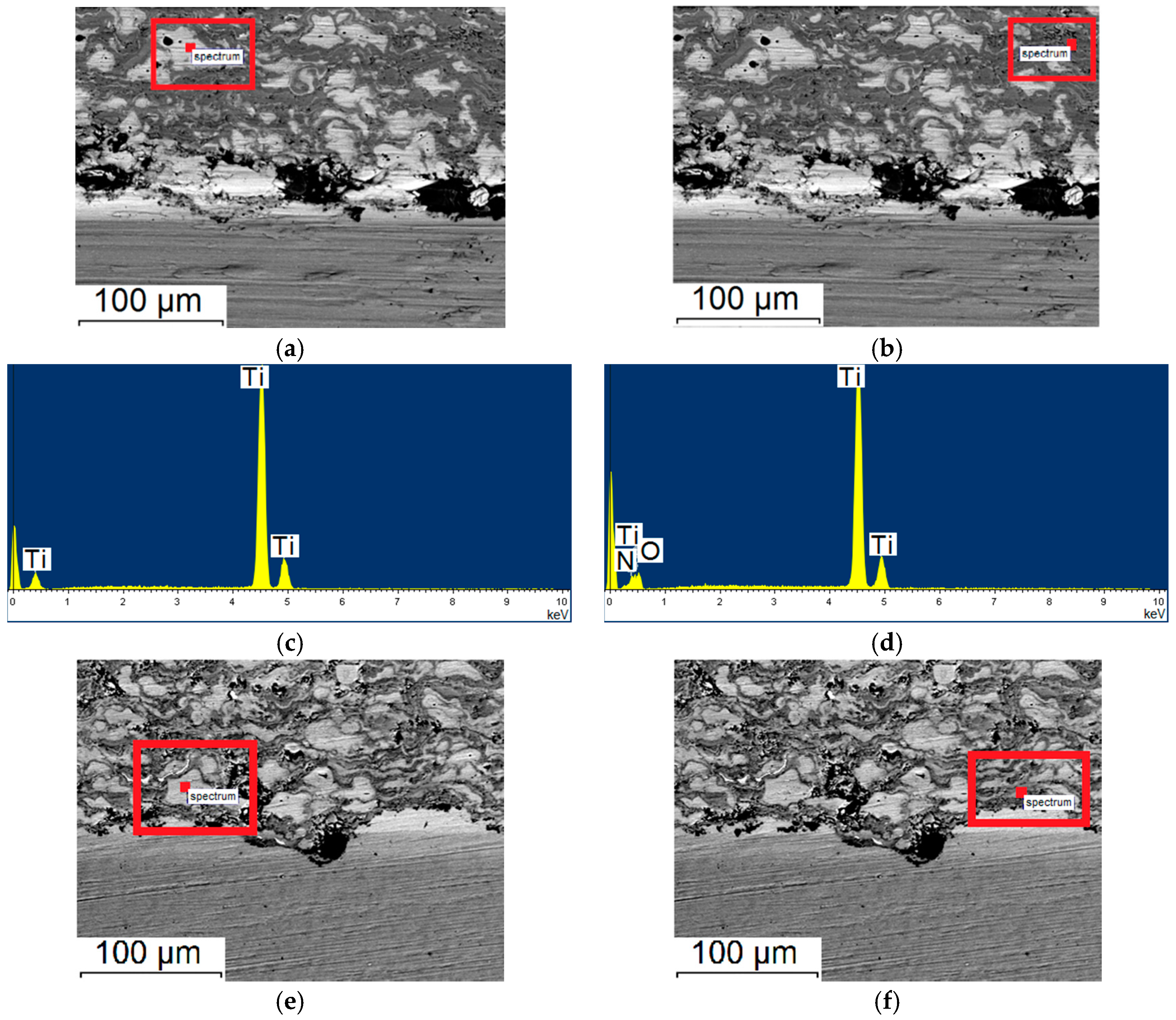
3.3. Coating Structure

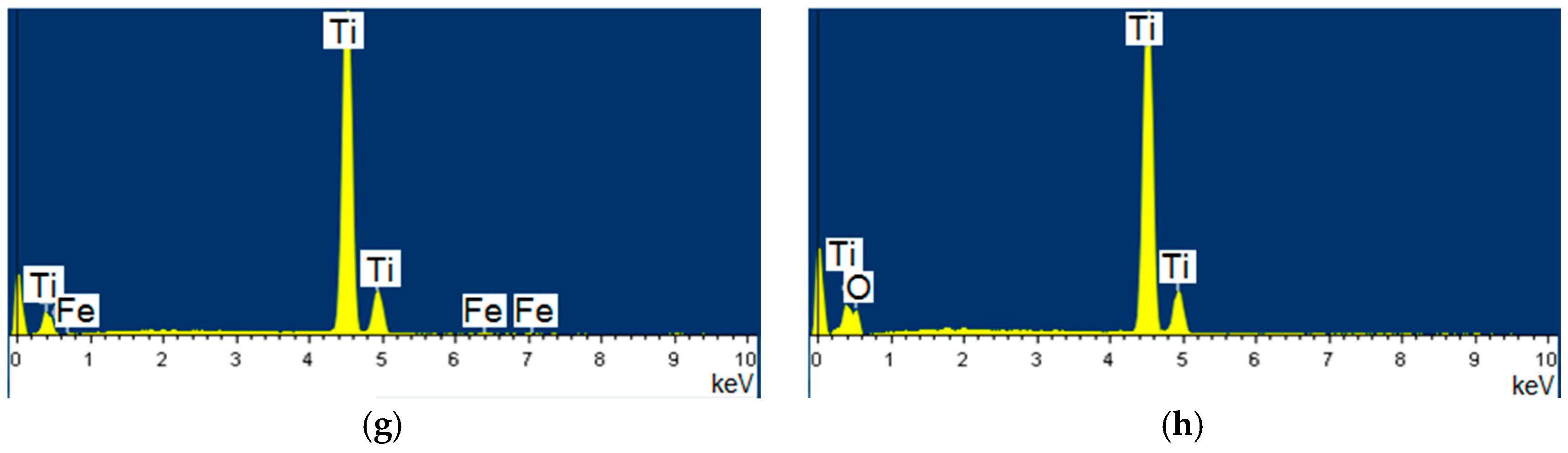
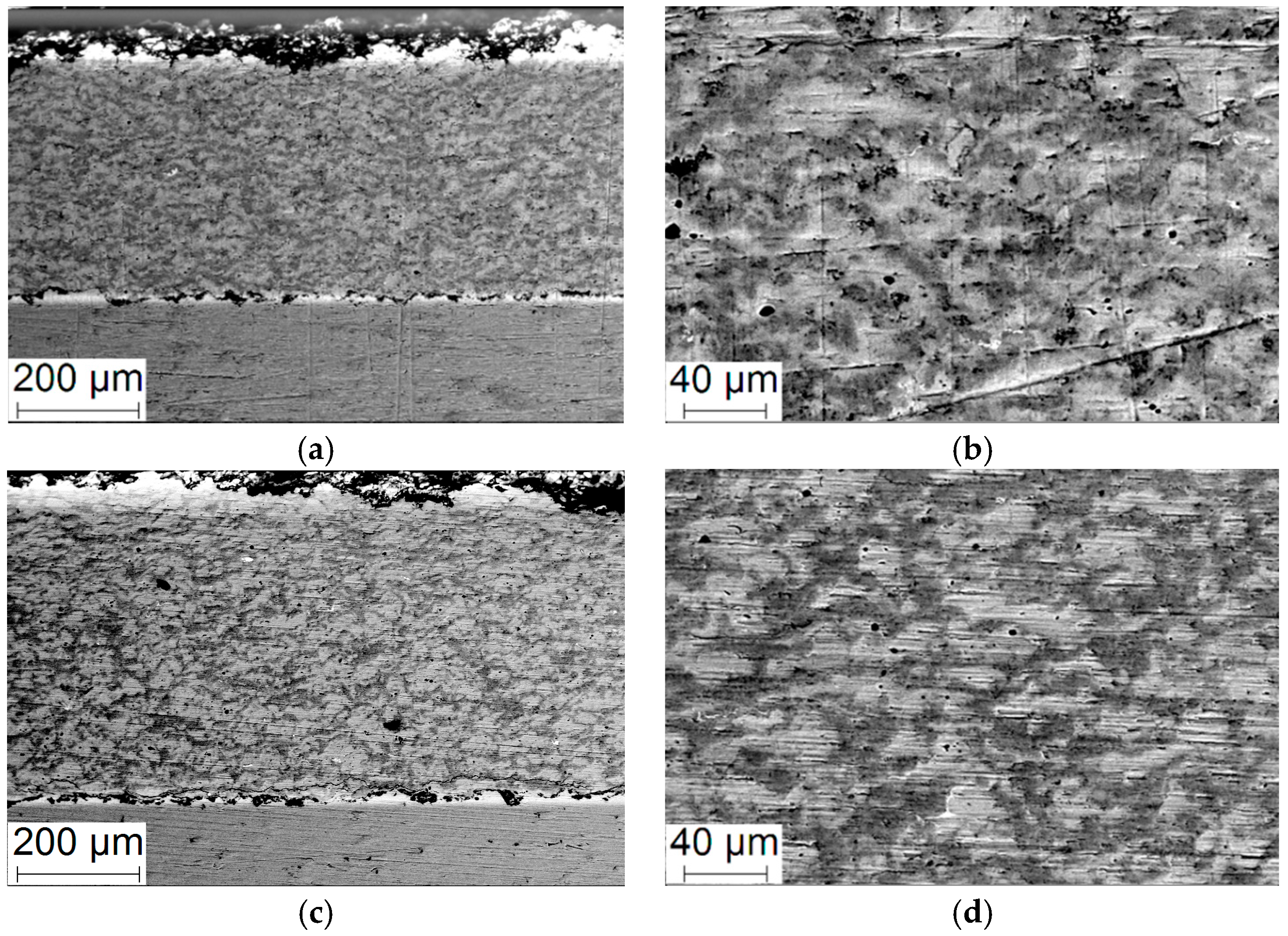
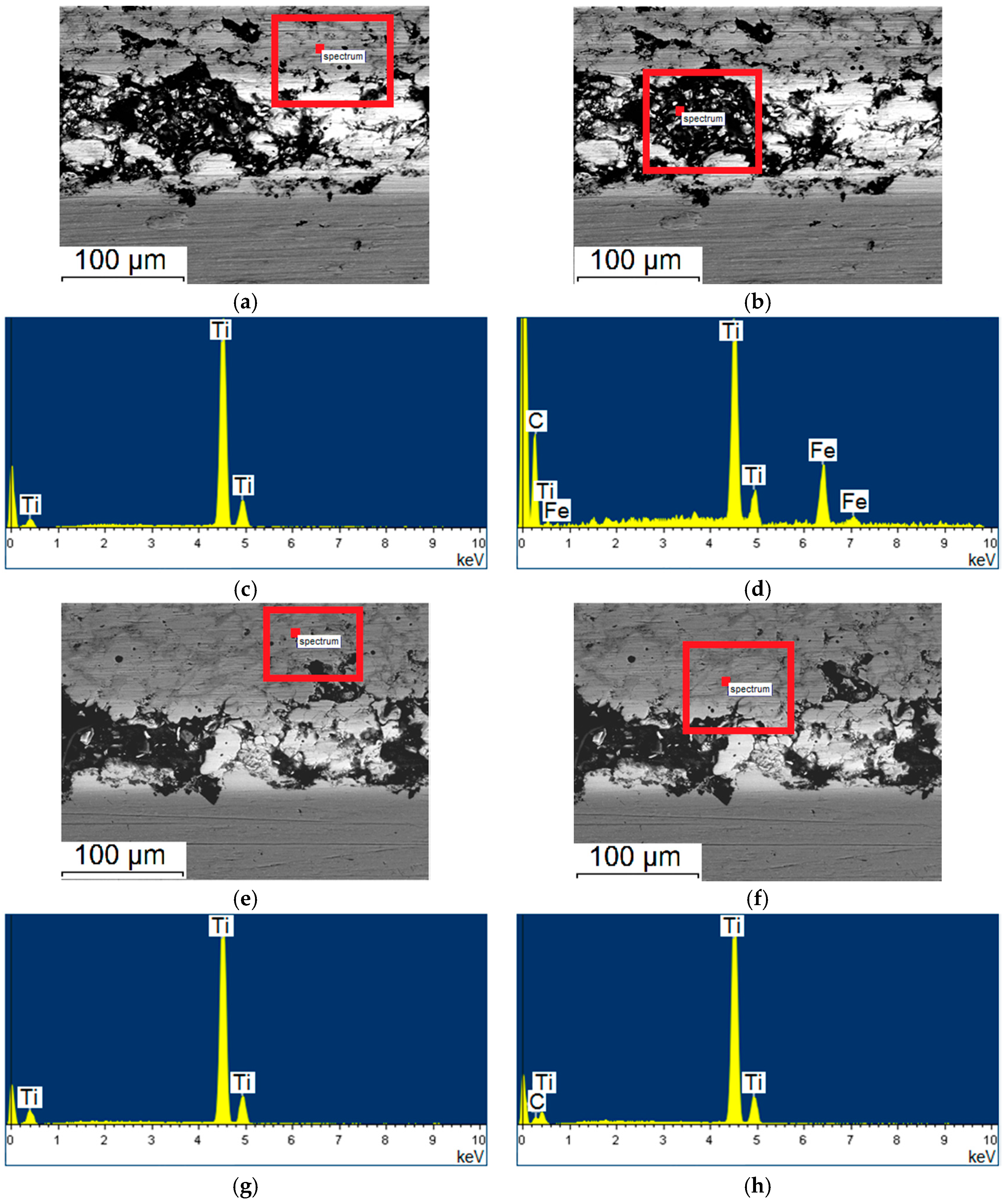
3.3.1. Spraying Regimes No. 1 and No. 2.

The analysis of the scanning electron microscope (SEM) images (Figure 2) shows that the coating consists of a set of densely packed splats, which is typical of coatings obtained by thermal spraying. SEM and EDS data of coating produced in regime No. 1 allow detecting titanium and its oxides. The formation of oxynitrides was confirmed by EDS; however, due to overlapping of titanium and nitrogen peaks in the EDS, the quantitative analysis is difficult to conduct.
The formation of the oxynitrides is related to the presence of nitrogen in the air (carrier gas). Metallic titanium in the micrographs is seen as bright regions against the background of a darker matrix of titanium oxides/oxynitrides. The oxygen content in such regions is ~35%. With the help of XRD, the phase composition of the coating and the size of the crystallites were determined (Table 3). It was found that the nanohardness of the regions corresponding to titanium oxides is 6 times higher than that of metallic titanium-rich regions (Figure 3, Table 3).
So, detonation spraying under the selected regime allows depositing a coating with a composite structure consisting of titanium and its oxides. The coating shows a low porosity and a uniform microstructure, which can be attributed to a uniform phase distribution over the entire coating volume (Figure 2). Coating produced in regime No. 2 has a similar structure; however, a larger number of splat-shaped inclusions of smaller sizes are observed. A noticeable number of micropores of round shape are a characteristic feature of the coating. The oxygen content in the oxide-rich regions is about 45%, which is higher than in specimen produced in regime No. 1 (Figure 3, Table 3). In the regions consisting mostly of metallic titanium, the presence of oxygen is also detected (less than 8%).
The key mechanical characteristics of coating produced in regime No. 2 are improved relative to those of coating produced in regime No. 1: the fracture initiation stress is increased by 43%, delamination stress—by 17%, and the interface fracture toughness—by 22%, (Table 2). These changes are associated with the formation of a high strength titanium oxide-based matrix.

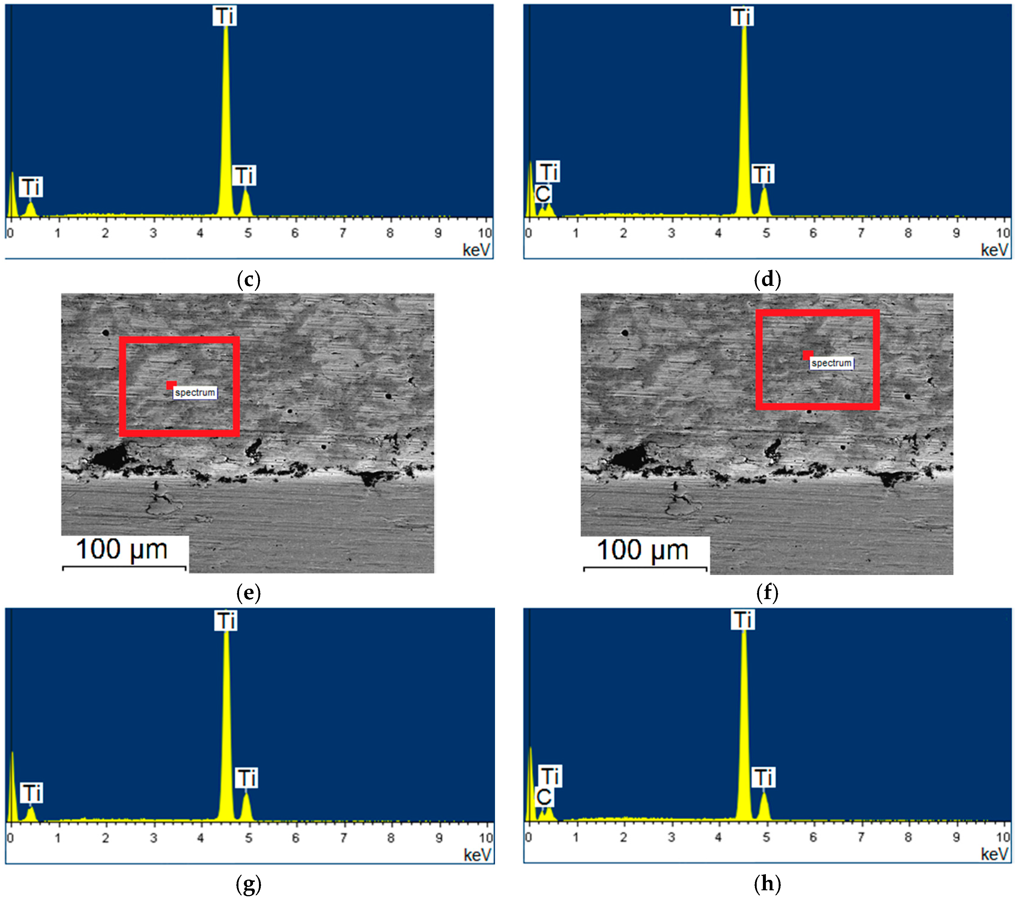
3.3.2. Spraying Regimes No. 3 and No. 4

A reduction in the oxygen content in the explosive mixture should result in a decrease in the content of the oxides in the coating. The use of nitrogen as a carrier gas can lead the formation of nitrides.
From the SEM micrographs of the specimen’s cross section (Figure 4), it can be seen that during the grinding/polishing process some particles detached from the surface. This indicates a reduced cohesive strength in comparison with specimens produced in regime No. 1 and No. 2. It is also clear that titanium particles have retained a predominantly globular shape after detonation spraying (their impact energy during spraying was not high). This result is most likely related to a substantial decrease in the spraying distance. A higher oxygen amount in the explosive mixture results in the formation of a coating with a higher strength (Figure 4a,b). This can also be the reason for a higher adhesion strength of the coating. As is seen from the Figure 4c,d, a greater number of dark regions are observed in coating produced in regime No. 4, which correspond to titanium carbonitrides.
A high porosity is a characteristic feature of specimen produced in regime No. 3 (Figure 5). Thin layers are located along the boundaries of the titanium particles. The oxygen content in these layers does not exceed 15% (Table 3), which is significantly lower than the oxygen content in specimens produced in regime No. 1 and No. 2. In large pores of the coating, a higher content of carbon is detected than in small pores (up to 35%). With the help of XRD, it was found that for both specimens, titanium nitride prevails as the reaction product.
Coating produced in regime No. 4 is denser than one produced in regime No. 3. A higher content of C2H2 in the explosive mixture has led to an increase in the carbon content in the coating, as is evidenced from the EDS data (Table 3). The carbon content along the titanium particle boundaries is ~25%, reaching 45% in large pores.

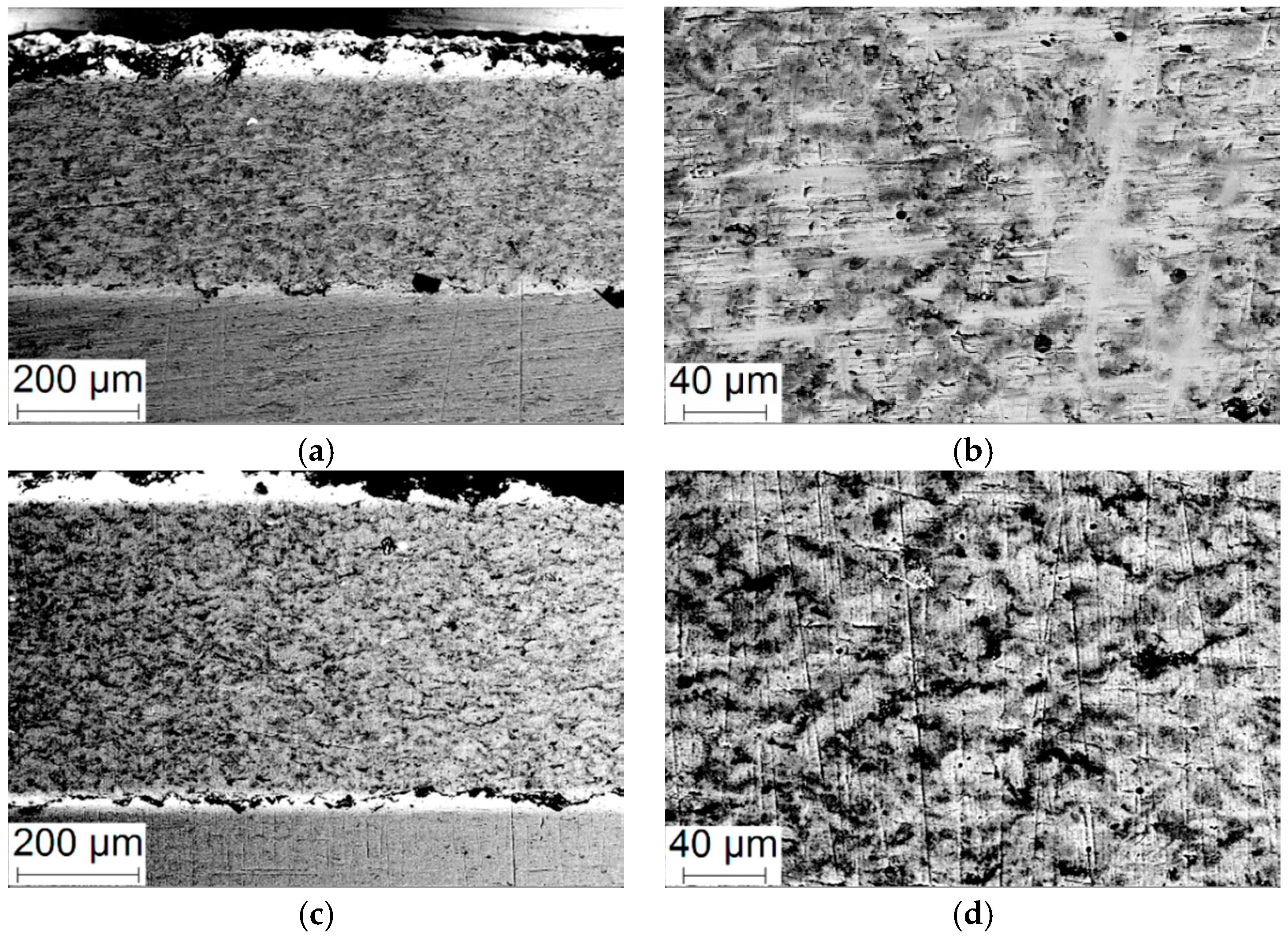
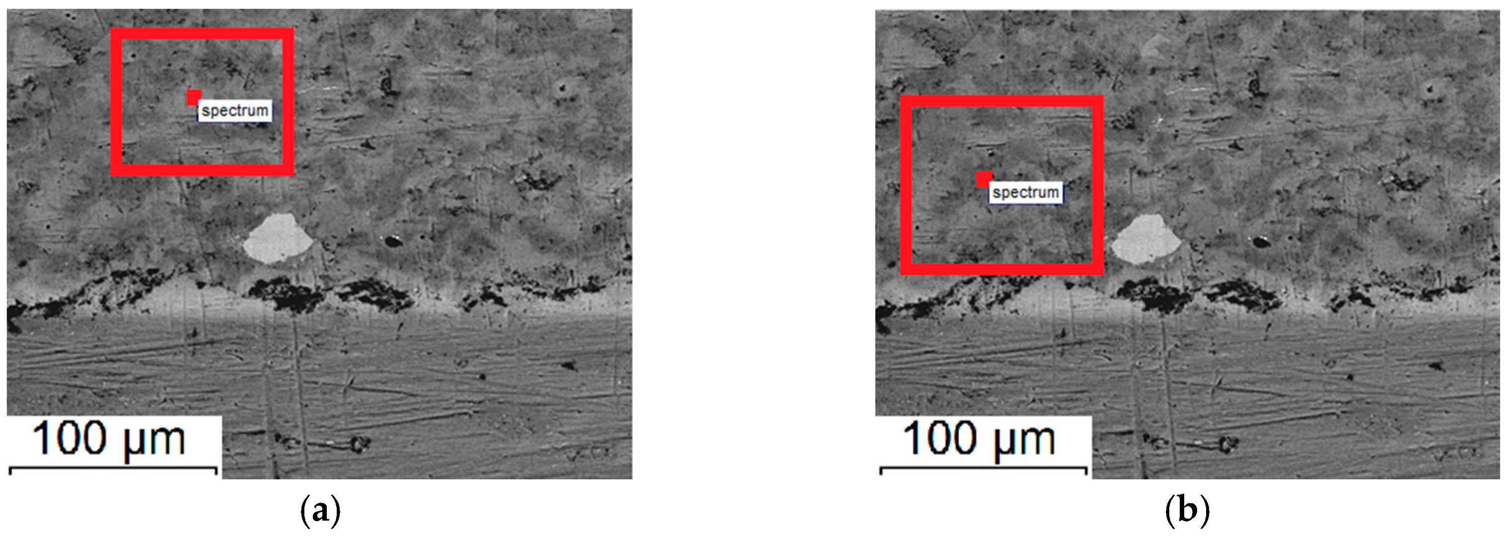
3.3.3. Spraying Regimes No. 5 and No. 6

For specimens produced in regime No. 5 and No. 6, the spraying distance was 10 mm and 100 mm, respectively. According to the SEM data, these coatings have a fine-grained structure (Figure 6), in which titanium particles are surrounded by ceramic grains.
According to the EDS of specimen produced in regime No. 5, the oxygen content outside of unreacted titanium particles phases does not exceed 10%, while the content of carbon is about 20%. In the similar regions of the microstructure of specimen produced in regime No. 6, the oxygen content is about 15%, while the carbon content is 25% (Figure 7, Table 3). It can be assumed that when a longer spraying distance is used, a greater transformation degree of titanium is achieved. Therefore, the interphase boundaries appear more distinct, while the oxygen and carbon contents in specimen produced in regime No. 6 are higher (Figure 6d). Using a shorter spraying distance, a coating with increased values of nano- and microhardness was obtained (specimen No. 5, Table 2 and Table 3). As compared to specimens produced in regime No. 3 and No. 4, the nanohardness value is almost twice as high (Table 3).
From comparison of the mechanical properties of the specimens, the following conclusions can be drawn. The thickness of the coating in specimen produced in regime No. 6 was 4 times greater than that in the rest of the specimens), which significantly affected the crack resistance measured during bending and scratching (σcr and Kc). Nevertheless, the bending cracking resistance of specimen produced in regime No. 5 is higher than that of specimen produced in regime No. 6. This can be attributed to more a uniform structure of specimen produced in regime No. 5. At the same time, the bending delamination stress of coating produced in regime No. 5 (Table 2) is noticeably higher than the values observed in coatings produced in regime No. 3 and No. 4.

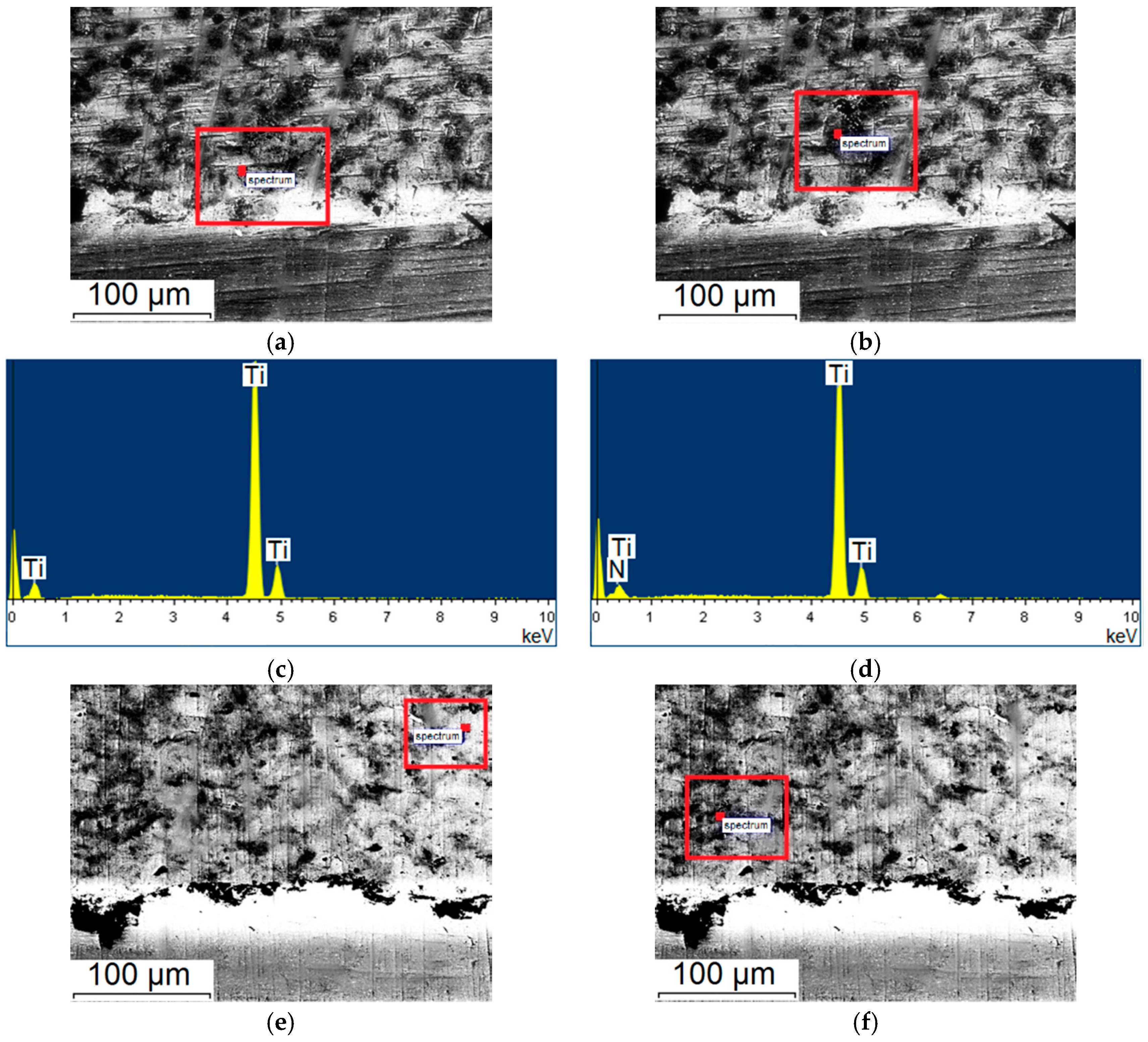
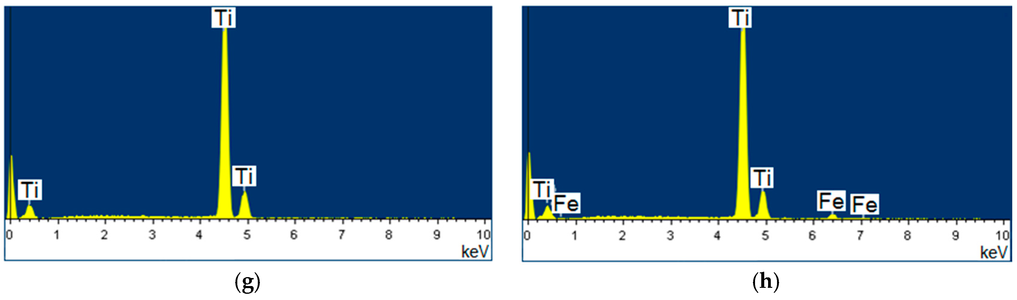
3.3.4. Spraying Regimes No. 7 and No. 8

The spraying distance was 10 mm for specimen produced in regime No. 7 while it was 100 mm for specimen produced in regime No. 8. Additionally, nitrogen was added to the O2/C2H2 mixture in an amount of 33% by volume. It was assumed that the introduction of nitrogen into the explosive mixture would favor the formation of nitrides in the coatings.
As seen in Figure 8, the coating structure is rather uniform and is represented by metallic titanium and ceramic phases. A number of small microcracks and round pores can be observed. An increase in the spraying distance for specimen produced in regime No. 8 has led to the formation of pronounced interphase boundaries due to a higher chemical transformation degree of titanium. The EDS data for specimen produced in regime No. 7 show that the carbon content in the coating is less than 6%, while the oxygen content is about 30% (Figure 9, Table 3).
In specimen produced in regime No. 8, the oxygen content was lower (15%), while the content of carbon did not change substantially. This could be the reason for a decrease in the microhardness. The nanohardness of specimens produced in regime No. 7 and No. 8 has, on the contrary, increased. In both specimens, titanium nitrides were found to dominate in the dark regions.
The bending delamination stress for specimen produced in regime No. 7 is higher than that of specimen No. 8 by 30%, while the cracking stress σcr increases by a factor of ~10. At the same time, the interface fracture toughness Kc is increased by 40% (Table 2). The introduction of nitrogen into the explosive mixture has increased the amount of titanium nitrides. This appears to be the reason for the improvement of the mechanical properties relative to specimens produced in regime No. 5 and No. 6. Specimen No. 7 possesses the maximum cracking resistance among the compositions studied.

4. Conclusions

The structure and mechanical properties of the coatings deposited by reactive detonation spraying of a titanium powder were studied for three characteristic compositions of the explosive mixture and simultaneous variation of other deposition parameters. The composition and nanohardness of the individual phases of the coatings as well as the effect of the spraying regimes on the mechanical properties of the coatings were investigated. For the three characteristic modes of the coating formation (the composition of the explosive mixture and the carrier gas), the following recommendations were formulated:
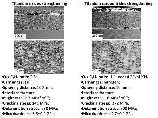
  • In case of the spraying with air as a carrier gas, no nitrogen added into the explosive mixture, an increase in the O2/C2H2 from 1.1 and 2.5 leads to an increase in the cracking resistance and coating delamination stress under three-point bending, as well as the interface fracture toughness under the scratch test due to formation of a hierarchically organized coating structure with clearly exhibited phase boundaries. Deposition of titanium at O2/C2H2 = 2.5 allows obtaining coatings with a high fracture toughness, a high adhesion strength, a high microhardness and a low friction coefficient.
  • In the event of spraying with nitrogen as a carrier gas, no nitrogen added into the explosive mixture, a short spraying distance (10 mm) and a low oxygen content in the explosive mixture (O2/C2H2 = 0.7) makes it possible to form a heterogeneous structure of the coating. This ensures mechanical properties comparable to those of the coatings, in which the oxide phases were predominantly formed. The coatings show a moderate crack resistance, a moderate adhesion strength, a high microhardness (H100 = 2.72 GPa) and a high friction coefficient (µ0 ~0.58).
  • In case of the spraying with nitrogen as a carrier gas and nitrogen added to the explosive mixture, the formation of a complex heterogeneous structure makes it possible to achieve a high crack resistance under three-point bending, a high interface fracture toughness under the scratch test and a high microhardness (H100 = 2.74 GPa). The friction coefficient of the coating was µ0 ~0.68.
Based on the results obtained, two detonation spraying regimes of titanium powders can be recommended for deeper R&D and practical applications. The first ensures strengthening of the coating by titanium oxides (use of the air as a carrier gas and high oxygen content in the explosive mixture). A more advanced deposition alternative produces strengthening by titanium carbonitrides with blurred interphase boundaries (short spraying distances, large explosive charges with nitrogen as a carrier gas and addition of N2 into the explosive mixture). The experimental data on the possibilities of obtaining detonation coatings containing titanium nitrides and oxides and having different structural characteristics can be used in the development of coatings for biomedical and catalytic applications, respectively.

Acknowledgments

The work was partially supported by Cheung Kong Scholar of Jilin University, and performed with a partial support by Grant No. 11.2 of the Russian Academy of Sciences (Department of Power Engineering, Mechanical Engineering, Mechanics, and Control Processes). The authors are grateful to “Nanotech” Shared Use Center of ISPMS SB RAS for the assistance in running fractographic investigations. The nanoindentation tests were carried out at Tomsk Polytechnic University within the framework of Tomsk Polytechnic University Competitiveness Enhancement Program grant.

Author Contributions

Igor Batraev performed detonation spraying, Ilya Vlasov, Roman Stankevich and Dina Dudina carried out experimental studies of the coatings, Sergei Panin, Ilya Vlasov, Dina Dudina and Vladimir Ulianitsky analyzed the data; Sergei Panin, Ilya Vlasov, Dina Dudina, Vladimir Ulianitsky, Filippo Berto wrote the paper.

Conflicts of Interest

The authors declare no conflict of interest. The founding sponsors had no role in the design of the study; in the collection, analyses, or interpretation of data; in the writing of the manuscript, and in the decision to publish the results.

References

  1. Deevi, S.C.; Sikka, V.K.; Swindeman, C.J.; Seals, R.D. Application of reaction synthesis principles to thermal spray coatings. J. Mater. Sci. 1997, 32, 3315–3325. [Google Scholar] [CrossRef]
  2. Fauchais, P.; Montavon, G.; Lima, R.S.; Marple, B.R. Engineering a new class of thermal spray nano-based microstructures from agglomerated nanostructured particles, suspensions and solutions: An invited review. J. Phys. D Appl. Phys. 2011, 44, 093001. [Google Scholar] [CrossRef] [Green Version]
  3. Kovaleva, M.; Tyurin, Y.; Kolisnichenko, O.; Prozorova, M.; Arseenko, M. Properties of detonation nanostructured titanium-based coatings. J. Therm. Spray Technol. 2013, 22, 518–524. [Google Scholar] [CrossRef]
  4. Zhao, L.; Lugscheider, E. Reactive plasma spraying of TiAl6V4 alloy. Wear 2002, 253, 1214–1218. [Google Scholar] [CrossRef]
  5. Fauchais, P.; Montavon, G.; Bertrand, G. From powders to thermally sprayed coatings. J. Therm. Spray Technol. 2010, 19, 56–80. [Google Scholar] [CrossRef]
  6. Valente, T.; Galliano, F.P. Corrosion resistance properties of reactive plasma-sprayed titanium composite coatings. Surf. Coat. Technol. 2000, 127, 86–92. [Google Scholar] [CrossRef]
  7. Ulianitsky, V.Y.; Dudina, D.V.; Batraev, I.S.; Kovalenko, A.I.; Bulina, N.V.; Bokhonov, B.B. Detonation spraying of titanium and formation of coatings with spraying atmosphere-dependent phase composition. Surf. Coat. Technol. 2015, 261, 174–180. [Google Scholar] [CrossRef]
  8. Yao, Y.; Wang, Z.; Zhou, Z.; Jiang, S.; Shao, J. Study on reactive atmospheric plasma-sprayed in situ titanium compound composite coating. J. Therm. Spray Technol. 2013, 22, 509–517. [Google Scholar] [CrossRef]
  9. Peat, T.; Galloway, A.; Toumpis, A.; McNutt, P.; Iqbal, N. The erosion performance of cold spray deposited metal matrix composite coatings with subsequent friction stir processing. Appl. Surf. Sci. 2017, 396, 1635–1648. [Google Scholar] [CrossRef]
  10. Klinkov, S.V.; Kosarev, V.F.; Sova, A.A.; Smurov, I. Deposition of multicomponent coatings by Cold Spray. Surf. Coat. Technol. 2008, 202, 5858–5862. [Google Scholar] [CrossRef]
  11. Sova, A.; Pervushin, D.; Smurov, I. Development of multimaterial coatings by cold spray and gas detonation spraying. Surf. Coat. Technol. 2010, 205, 1108–1114. [Google Scholar] [CrossRef]
  12. Panin, V.; Gromov, V.; Romanov, D.; Budovskikh, E.; Panin, S. The Physical Basics of Structure Formation in Electroexplosive Coatings. Dokl. Phys. 2017, 472, 650–653. [Google Scholar] [CrossRef]
  13. Dongmo, E.; Wenzelburger, M.; Gadow, R. Analysis and optimization of the HVOF process by combined experimental and numerical approaches. Surf. Coat. Technol. 2008, 202, 4470–4478. [Google Scholar] [CrossRef]
  14. Smurov, I.; Ulianitsky, V. Technology vision. Surf. Eng. 2011, 27, 557–559. [Google Scholar] [CrossRef]
  15. Senderowski, C.; Chodala, M.; Bojar, Z. Corrosion behavior of detonation gun sprayed Fe-Al type intermetallic coating. Materials 2015, 8, 1108–1123. [Google Scholar] [CrossRef] [PubMed]
  16. Saladi, S.; Menghani, J.; Prakash, S. Effect of CeO2 on cyclic hot-corrosion behavior of detonation-gun sprayed Cr3C2-NiCr coatings on Ni-based superalloy. J. Mater. Eng. Perform. 2015, 24, 1379–1389. [Google Scholar] [CrossRef]
  17. Senderowski, C. Nanocomposite Fe-Al Intermetallic coating obtained by gas detonation spraying of milled self-decomposing powder. J. Therm. Spray Technol. 2014, 23, 1124–1134. [Google Scholar] [CrossRef]
  18. Ibrahim, A.; Berndt, C.C. Fatigue and deformation of HVOF sprayed WC-Co coatings and hard chrome plating. Mater. Sci. Eng. A 2007, 456, 114–119. [Google Scholar] [CrossRef]
  19. Rajasekaran, B.; Raman, S.G.S.; Joshi, S.V.; Sundararajan, G. Performance of plasma sprayed and detonation gun sprayed Cu-Ni-In coatings on Ti-6Al-4V under plain fatigue and fretting fatigue loading. Mater. Sci. Eng. A 2008, 479, 83–92. [Google Scholar] [CrossRef]
  20. Rodríguez-Barrero, S.; Fernández-Larrinoa, J.; Azkona, I.; de Lacalle, L.N.L.; Polvorosa, R. Enhanced performance of nanostructured coatings for drilling by droplet elimination. Mater. Manuf. Proc. 2016, 31, 593–602. [Google Scholar] [CrossRef]
  21. de Lacalle, L.N.L.; Lamikiz, A.; Fernandes, M.H.; Gutiérrez, A.; Sánchez, J.A. Turning of thick thermal spray coatings. J. Therm. Spray Technol. 2001, 10, 249–254. [Google Scholar] [CrossRef]
  22. Toma, F.L.; Bertrand, G.; Chwa, S.O.; Klein, D.; Liao, H.; Meunier, C.; Coddet, C. Microstructure and photocatalytic properties of nanostructured TiO2 and TiO2-Al coatings elaborated by HVOF spraying for the nitrogen oxides removal. Mater. Sci. Eng. A. 2006, 417, 56–62. [Google Scholar] [CrossRef]
  23. Ulianitsky, V.; Shtertser, A.; Zlobin, S.; Smurov, I. Computer-controlled detonation spraying: From process fundamentals toward advanced applications. J. Therm. Spray. Technol. 2011, 20, 791–801. [Google Scholar] [CrossRef]
  24. Isakov, M.; Matikainen, V.; Koivuluoto, H.; May, M. Systematic analysis of coating-substrate interactions in the presence of flow localization. Surf. Coat. Technol. 2017, 324, 264–280. [Google Scholar] [CrossRef]
  25. Gere, J.; Goodno, B. Mechanics of Materials, 7th ed.; Cengage Learning: Toronto, ON, Canada, 2008; pp. 352–454. [Google Scholar]
  26. Zhou, Y.C.; Tonomori, T.; Yoshida, A.; Liu, L.; Bignall, G.; Hashida, T. Fracture characteristics of thermal barrier coatings after tensile and bending tests. Surf. Coat. Technol. 2002, 157, 118–127. [Google Scholar] [CrossRef]
Figure 1. (a) three-point bending diagram for coated titanium specimens; (b,c) scratching diagrams of the coatings.
Metals 07 00355 g001
Figure 2. Scanning electron microscope (SEM)-micrographs of the cross section of specimens produced in regime No. 1 (a,b) and No. 2 (c,d).
Metals 07 00355 g002
Figure 3. Micrographs of the coating cross-section and Energy Dispersive Spectroscopy (EDS) results: specimen produced in regime No. 1 (ad) and No. 2 (eh). A circle within red rectangle shows the location where EDS analysis was carried out.
Metals 07 00355 g003aMetals 07 00355 g003b
Figure 4. SEM-micrographs of the coating cross-section of specimens produced in regime No. 3 (a,b) and No. 4 (c,d).
Metals 07 00355 g004
Figure 5. Micrographs of the coating cross-section and EDS results: specimen produced in regime No. 3 (ad) and No. 4 (eh). A circle within red rectangle shows the location where EDS analysis was carried out.
Metals 07 00355 g005
Figure 6. SEM-micrographs taken at the cross section of the specimens produced in regime No. 5 (a,b) and No. 6 (c,d).
Metals 07 00355 g006
Figure 7. SEM-micrographs of the coating cross-section and EDS results: specimen produced in regime No. 5 (ad) and No. 6 (eh). A circle within red rectangle shows the location where EDS analysis was carried out
Metals 07 00355 g007aMetals 07 00355 g007b
Figure 8. SEM micrographs of the cross sections of specimens produced in regime No. 7 (a,b) and No. 8 (c,d).
Metals 07 00355 g008
Figure 9. Micrographs of the coating cross-section and EDS results: specimen produced in regime No. 7 (ad) and No. 8 (eh). A circle within red rectangle shows the location where EDS analysis was carried out.
Metals 07 00355 g009aMetals 07 00355 g009b
Table 1. Parameters of detonation spraying and the coating thickness.
Spraying RegimeO2/C2H2Spraying Distance, mmExplosive Charge, %Carrier GasCoating Thickness (hcoat), μm
11.110030air270
22.510030air275
31.11040nitrogen160
40.71040nitrogen291
50.71050nitrogen190
60.710050nitrogen750
71.1 + added 33 vol % N21060nitrogen235
81.1 + added 33 vol % N210060nitrogen285
Table 2. Mechanical properties of the coatings and coated specimens measured by scratch tests and 3-point bending.
No.σ2.5, MPaσcr, MPaσdelam, MPaKc, MPa·m1/2τ, MPaHμ, GPaFriction Coefficient, μ0Maximum Depth of the Scratch, μm
195598.454010.4237.33.70 ± 0.030.40666.6
2850140.563012.7295.33.84 ± 0.070.41263.4
382587.96204.873.12.68 ± 0.070.63783.3
4105544.9700.910.92.45 ± 0.110.661140.5
594594.27307.6132.92.72 ± 0.090.58050.7
687010650--2.02 ± 0.010.594102.2
7945372.180011.6228.72.74 ± 0.090.675103.5
887533.55606.893.12.29 ± 0.020.58580.9
Table 3. Microstructure characteristics and nanohardness of the coatings detonation sprayed under various regimes.
Regime No.Characteristic Regions on the Cross-SectionChemical Composition Determined by EDS, at. %Phases Detected by the XRDCrystallite Size, nmNanohard-Ness, GPa
1Bright areasTi ~99%, O ~1%--2.7 ± 1
Dark areasTi ~65%, O ~35%TiNxOy2016.3 ± 3
TiO25
Ti2O330
2Bright areasTi ~92%, O ~8%--7.8 ± 2
Dark areasTi ~55%, O ~45%TiO-9.7 ± 2
Ti2O3
Ti3O5
TiO2
3Bright areasTi ~94%, O ~6%--3.9 ± 0.6
Dark areasTi ~50%, O ~15%, C ~35%TiN207.7 ± 1.4
TiN0.320
4Bright areasTi ~94%, O ~6%--1.8 ± 0.8
Dark areasTi ~70%, O ~5%, C ~25%TiNvCw203.6 ± 1.5
5Bright areasTi ~93%, O ~7%--4.6 ± 0.8
Dark areasTi ~70%, O ~10%, C ~20%TiNvCw207.6 ± 1.7
6Bright areasTi ~97%, O ~3%--1.8 ± 0.6
Dark areasTi ~60%, O ~15%, C ~25%TiNvCw306.8 ± 1.6
TiC80
TiN25
TiN0.310
7Bright areasTi ~95%, O ~5%--2.5 ± 0.4
Dark areasTi ~64%, O ~30%, C ~6%TiN354.5 ± 1
TiN0.325
8Bright areasTi ~95%, O ~5%--4.6 ± 0.5
Dark areasTi ~77%, O ~15%, C ~8%TiN-6.8 ± 1.8
TiN0.3

