Influence of Powder Surface Contamination in the Ni-Based Superalloy Alloy718 Fabricated by Selective Laser Melting and Hot Isostatic Pressing

Department of Mechanical Engineering, Tokyo Metropolitan University, 1-1 Minami-Osawa, Hachioji-Shi, Tokyo 192-0397, Japan
*
Author to whom correspondence should be addressed.
Metals 2017, 7(9), 367; https://doi.org/10.3390/met7090367
Submission received: 9 May 2017
/
Revised: 5 September 2017
/
Accepted: 7 September 2017
/
Published: 13 September 2017
(This article belongs to the Special Issue Powder Synthesis and Processing)
Abstract
:The aim of this study was to gain a deep understanding of the microstructure-mechanical relationship between solid-state sintering and full-melting processes. The IN718 superalloy was fabricated by hot isostatic pressing (HIP) and selective laser melting (SLM). Continuous precipitates were clearly localized along the prior particle boundary (PPB) in the HIP materials, while SLM materials showed a microstructure free of PPB. The mechanical properties of specimens that underwent SLM + solution treatment and aging were comparable to those of conventional wrought specimens both at room temperature and 650 °C. However, a drop was observed in the ductility of HIP material at 650 °C. The brittle particles along the PPB were found to affect the HIP materials’ creep life and ductility during solid-state sintering.
1. Introduction
IN718 superalloy is widely used in gas turbine and related aerospace applications due to its excellent hot corrosion resistance, good weldability, and high mechanical properties—e.g., creep and fatigue strengths [1,2,3]. Macro segregation occurs during the conventional ingot metallurgy route due to melt-related problems such as segregation and porosity, which lead to degradation of the mechanical properties of the alloys [4,5]. One solution to this problem was to minimize segregation through rapid solidification of the metal or through the solid-state sintering process. A powder metallurgy technology—i.e., hot isostatic pressing (HIP)—was developed to eliminate segregation and macro-porosity, and to manufacture net shape components with homogeneous microstructure and improved mechanical properties [6]. Moreover, the temperature involved in the HIP process allows segregants to diffuse, thus enhancing the mechanical properties. After this type of solid-state sintering process, special care—i.e., rolling, extrusion and forging—is required to mitigate the detrimental effects of prior particle boundary (PPB) precipitation [7]. The so-called PPB problem results from surface contamination with pre-alloyed powder, and particles such as oxides, carbides, oxy-carbides and oxycarbonitrides are formed along the PPB [8,9,10]. These precipitates along the PPB are brittle and thus provide an easy fracture path, and so the undesirable effects of PPBs have been focused on because they limit the applications of such consolidated products in HIPed materials [11]. Although many efforts have been made to decrease the effects of PPBs to extend the life of such products in applications in the aerospace industry, no effective and reliable method has yet been determined. Hence, an additive manufacturing technology, selective laser melting (SLM), was used in the current research. The laser beam irradiates metal powders until they fully melt in the SLM process, which has the benefit of causing PPB breakdown. SLM is applicable to components of fully dense bulk material with complex geometry [12]. In spite of the fact that the process is capable of making full density (~98–99%) parts, post-processes such as HIP were commonly used to eliminate the small amount of residual porosity for critical applications where high strength and fatigue resistance were necessary [13,14]. The obvious characteristics of the mechanical properties of SLM parts include anisotropy; the reasons for the special characteristics of IN718 built up by SLM—e.g., the high dislocation density, subgrain boundary and a row of interdendritic δ-phase precipitates—have been explained in our previous studies from several perspectives [15,16]. However, research related to the surface contamination on powder in SLM materials is limited. Therefore, the current study focused on surface contamination and on the consolidation behaviour between SLM and conventional HIP. In order to gain an in-depth understanding of the surface contamination by the powder both in the SLM and HIP processes, the microstructure-mechanical relationship of IN718 nickel-based alloy fabricated by HIP and SLM processes were compared in the current study.
2. Materials and Experimental Procedure
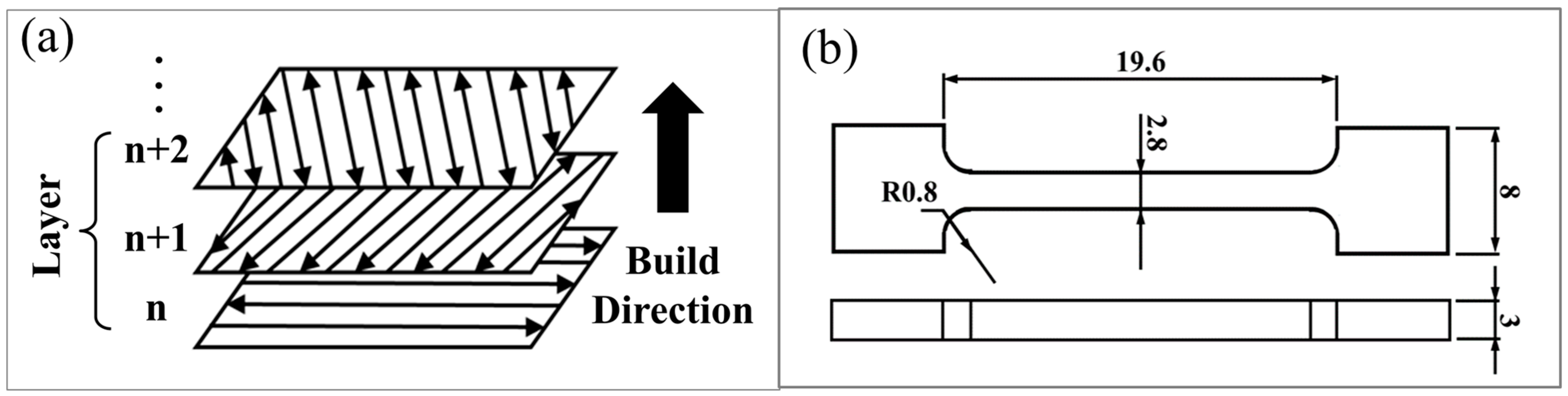
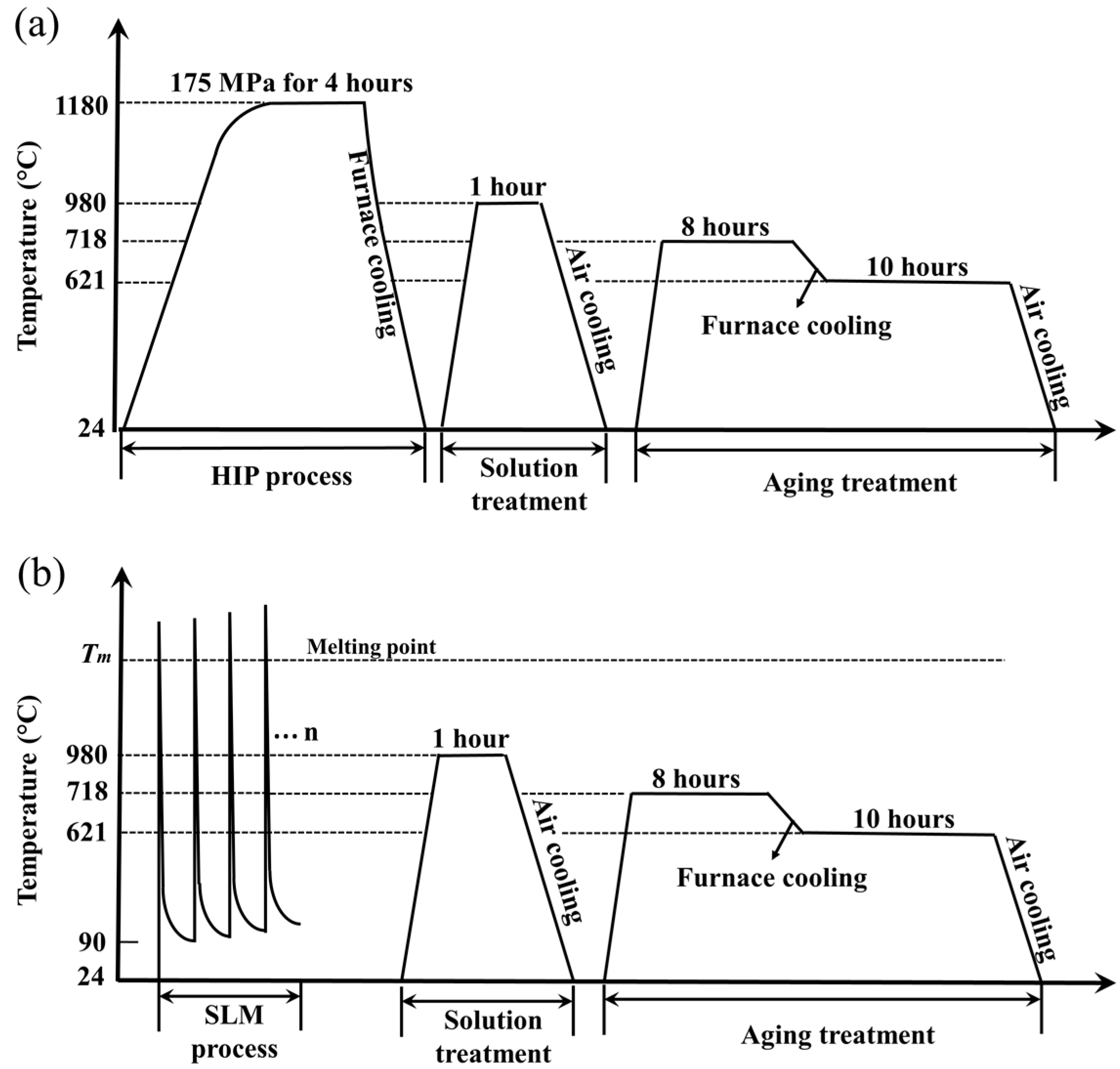
The prealloyed IN718 superalloy powder was prepared by vacuum melting and atomized into powders using the gas-atomizing method. The gas-atomized IN718 powders used for both the HIP process and the SLM process were typically spherical particles that were finer and had a broad particle size distribution below 60 μm (Figure 1), which may provide high packing density and reduce the percentage of voids [17,18]. The chemical composition of IN718 powder used in the HIP and SLM processes is shown in Table 1. The oxygen contents in the powders used for HIP and SLM were comparable. For the HIP process, the powders were entirely canned into SUS304 stainless steel capsules which was heated and evacuated to 1.0 × 10⁻³ Pa by an oil-diffusion pump. An optimal HIP condition which consisting of a soaking temperature of 1180 °C and a pressure of 175 MPa for 4 h was used [19]. On the other hand, a set of SLM process parameters (laser power: 400 W; scanning speed: 7.0 m/s; layer pitch: 20 μm; layer thickness: 40 μm; beam diameter: 100 μm; atmosphere: pure 99.9999% argon) was utilized to fabricate an IN 718 cube with the dimensions 35 × 35 × 35 mm3. The SLM cube was built using the alternating scan vector with a 66.7° rotation of the scanning direction. The scanning strategy of SLM process that were used are illustrated in Figure 2a. After the HIP and SLM processes, the specimens were subjected to solution treatment and aging (STA): a solution treatment at 980 °C for 1 h/air cooling (AC) to room temperature and a two-step aging treatment consisting of 718 °C for 8 h/furnace cooling to 621 °C and holding at 621 °C for 10 h before AC to room temperature. The heat histories of the specimens are shown in Figure 3a,b. Tensile test and creep test specimens were cut from the HIPed ingots and cubed using a spark cutter, and the gage length of each was 19.6 × 2.8 × 3.0 mm3 (Figure 2b). The tensile tests were conducted at room temperature (25 °C) and at 650 °C under a strain rate of 4.25 × 10⁻⁴ s−1. The creep test was conducted at 650 °C and 550 MPa. The microstructures were observed by a scanning electron microscope (HITACHI S-3700N, Tokyo, Japan), and transmission electron microscope (TEM, JEOL JEM-3200FS, Tokyo, Japan). Inverse pole figures (IPF) were calculated from the orientation measurements by electron backscatter diffraction (EBSD, Oxford Instruments, Oxfordshire, UK). X-ray diffraction (XRD, Rigaku Ultima IV, Tokyo, Japan) was used to determine the relative amounts of phases in the specimens.
3. Results
3.1. Microstructures of as-HIPed Specimen and as-Built Specimen
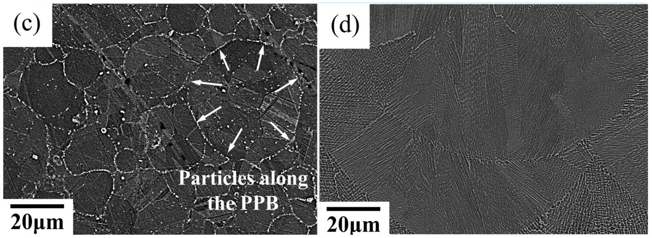
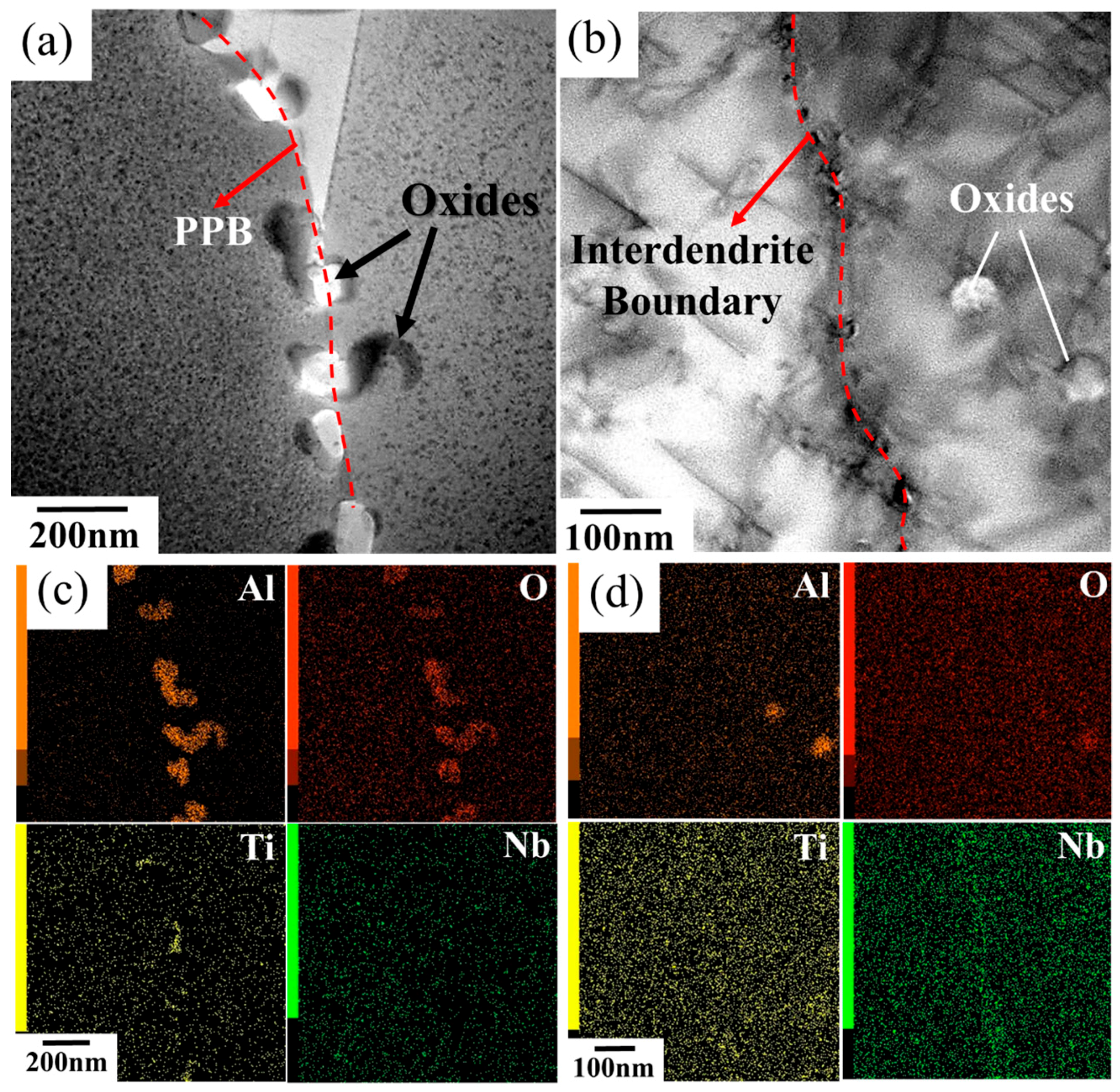
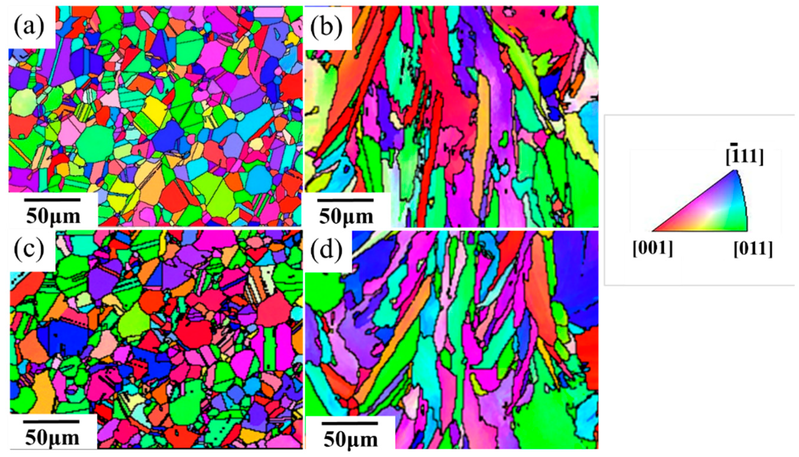
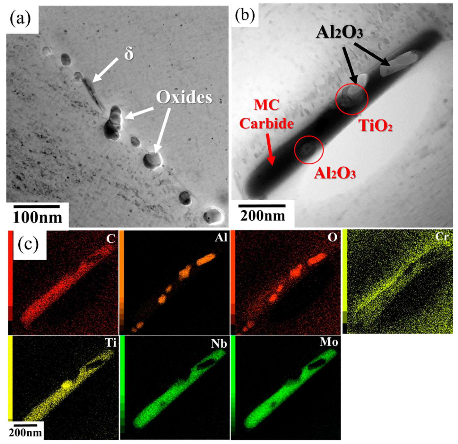
Densities of HIP and SLM, C&W alloys were 8.19, 8.18, and 8.20 g/cm3 respectively, as determined by the Archimedes principle. Investigation by X-ray diffraction (XRD) revealed the major peaks of γ matrix, while the oxide peaks such as Al2O3 or TiO2 could not be identified due to the limited volume fraction (Figure 4). Earlier studies showed comparable results which did not show the oxides peaks in the as-HIPed and as-built SLM specimens [19,20,21]. However, the clearly continuous precipitates were localized along the PPB in the as-HIPed specimen from the SEM observations (Figure 1c). The precipitates along the PPB in the as-HIPed specimen were mainly oxides (Figure 5a,c). Al, which easily reacts with oxygen, was found to be the major metallic element in an oxide layer of Al2O3 (Figure 5c). By contrast, the as-built specimen built up by the SLM process showed a free-PPB microstructure (Figure 1d). Oxides and carbides induced by oxygen and carbon contamination of pre-alloyed powder were rarely found in the as-built SLM specimen (Figure 5b). EBSD measurements were used to establish the crystallographic orientation of the γ matrix for all of the specimens. The orientations were colored in terms of a [001] inverse pole figure coloring scheme as shown in the legend (Figure 6). IPF maps of the as-HIPed and as-built specimens are shown in Figure 6a,b by means of EBSD, respectively. The equiaxed grains with an average size of 8.8 μm were observed in the as-HIPed specimen (Figure 6a), whereas the columnar grains were observed in the as-built specimen built up by the SLM process (Figure 6b). These columnar grains were attributed to the epitaxial growth and heat flux during the solidification in the SLM process [22].
3.2. Influence of the Heat-Treatment Process
IPF maps of the HIP + STA specimen and SLM + STA specimen are shown in Figure 6c,d, respectively. The SLM + STA specimen had IPF images similar to those of the as-built specimen (Figure 6b,d). For the HIP materials, the equiaxed grains structure could be observed both before and after the heat-treatment process (Figure 6a,c). The fine equiaxial grains were observed in the HIP materials because of the presence of the PPB, which would impede grain growth [23]. Moreover, carbides along the PPB appeared to increase after heat treatment when compared with as-HIPed material (Figure 7). The previous oxides along the PPB promoted the subsequent precipitation of carbides, since specific oxides act as nuclei for the formation of MC-type carbides or M23C6-type carbides along the PPB (Figure 7). During the heat-treatment process, titanium and carbon within the powder would migrate to the specific oxides on the particle surfaces, resulting in the formation of stable titanium oxy-carbides along the PPB [24].
3.3. Tensile Properties
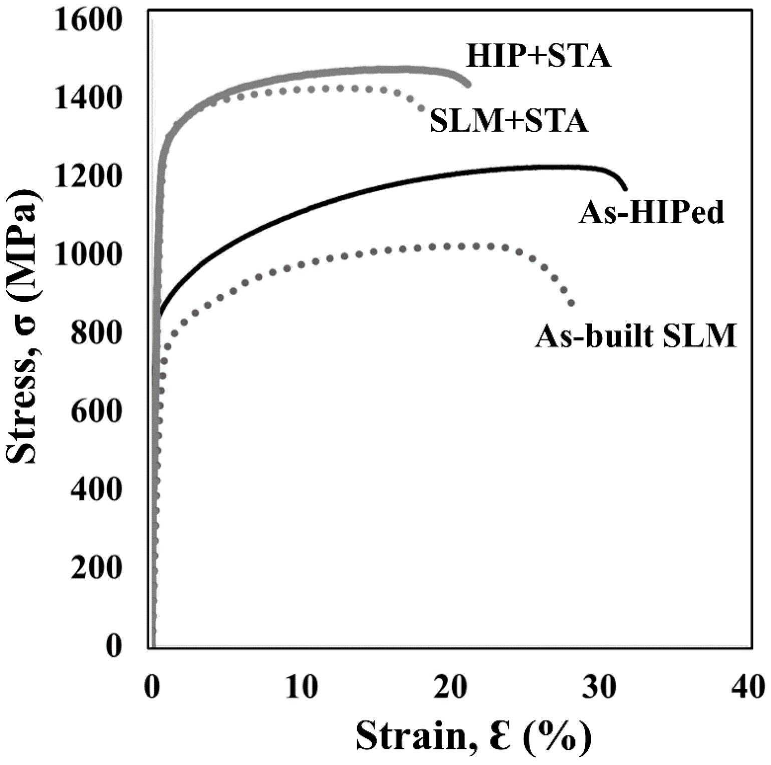
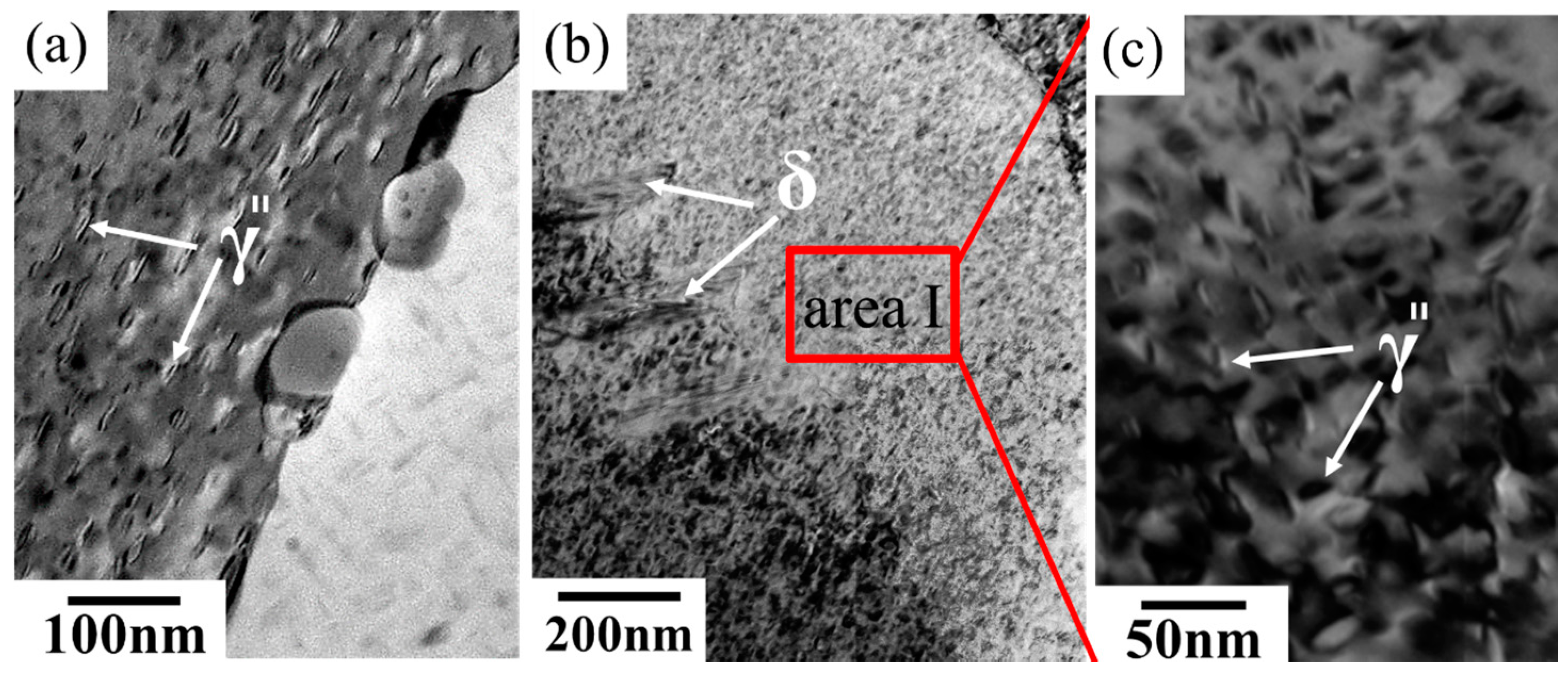
Engineering stress-strain curves and the tensile properties at room temperature and 650 °C are shown in Figure 8 and Figure 9, Table 2 and Table 3, respectively. At room temperature, the as-built specimen of SLM material showed lower tensile properties than those of the as-HIPed material (Figure 8). After the STA heat-treatment process, the proof and tensile strengths of the SLM materials were improved significantly compared with the as-built SLM materials (Table 2 and Figure 8). The tensile properties in the heat-treated materials were comparable to those of the conventionally wrought specimen at room temperature, as shown in Table 2. The principal strengthening phase in IN718 was the γ″ precipitate that promoted the strengths of heat-treated materials (Figure 10). The ductility of SLM + STA materials at room temperature was related to the fine dimples present on the fracture surface (Figure 11b). It was also noted that a mixed fracture surface which consisted of fine dimples and a few particle boundary facets was observed in the HIP + STA material (Figure 11a). The strengths and ductility of the SLM + STA specimen were comparable to those of the conventionally wrought specimens, both at room temperature and 650 °C, as shown in Table 2 and Table 3. However, the ductility of the HIP + STA specimen was much lower than those of the conventionally wrought specimen and the SLM + STA specimen at 650 °C (Table 3). The ductility of the HIP + STA specimen was only one-tenth of that of the cast and wrought specimen at 650 °C (Table 3). A fracture surface was observed along the grain boundaries covered with PPB in the HIP + STA specimen (Figure 11c), whereas, fracture surface specimens were observed along the dendrite structure in the SLM + STA (Figure 11d).
3.4. Creep Properties
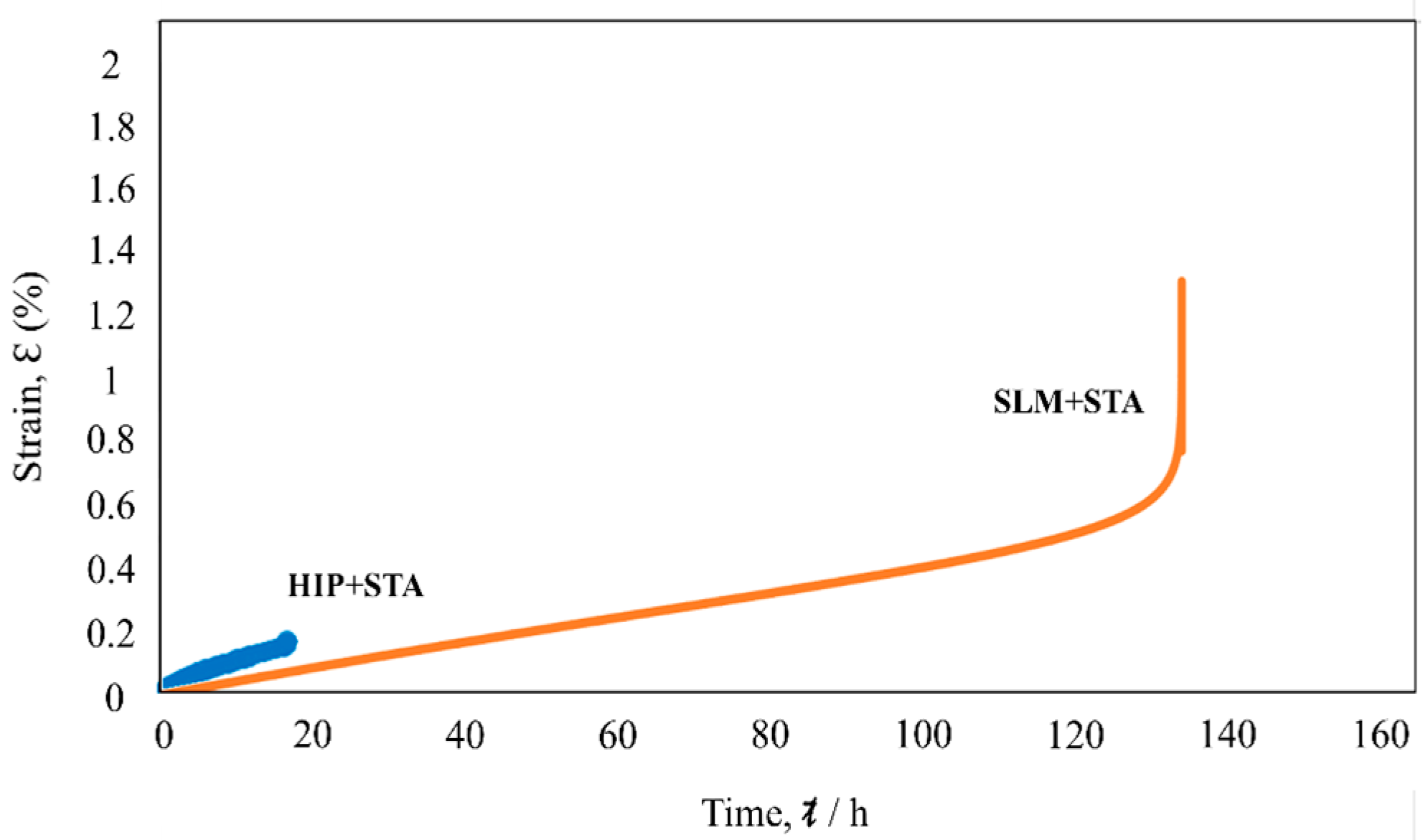
The creep curves of heat-treated specimens at 650 °C and 550 MPa are shown in Figure 12. As for the SLM + STA specimen, the creep rupture life was approximately 140 h, while the HIP + STA specimen exhibited a rupture life of only 20 h. The fracture surface was observed along the grain boundaries covered with PPB in the HIP + STA specimen as shown in Figure 13a.
4. Discussion
4.1. Grain Morphologies of SLM Materials
Equiaxed grains with an average size of 8.8 μm were observed in the HIP specimens (Figure 6a), whereas columnar grains were observed in the SLM specimens (Figure 6b). The columnar grains were attributed to the epitaxial growth which resulted from the partial melting of the back of the previous layer to promote growth from the prior grains of the previous layer in the [001] direction [25]. In addition, fine and equiaxed grains with a grain size of less than 1 μm were also observed in the SLM specimens (Figure 6b). Fine grains can be formed by the constitutional supercooling mechanism [26].
4.2. The Formation of PPB in HIP Materials
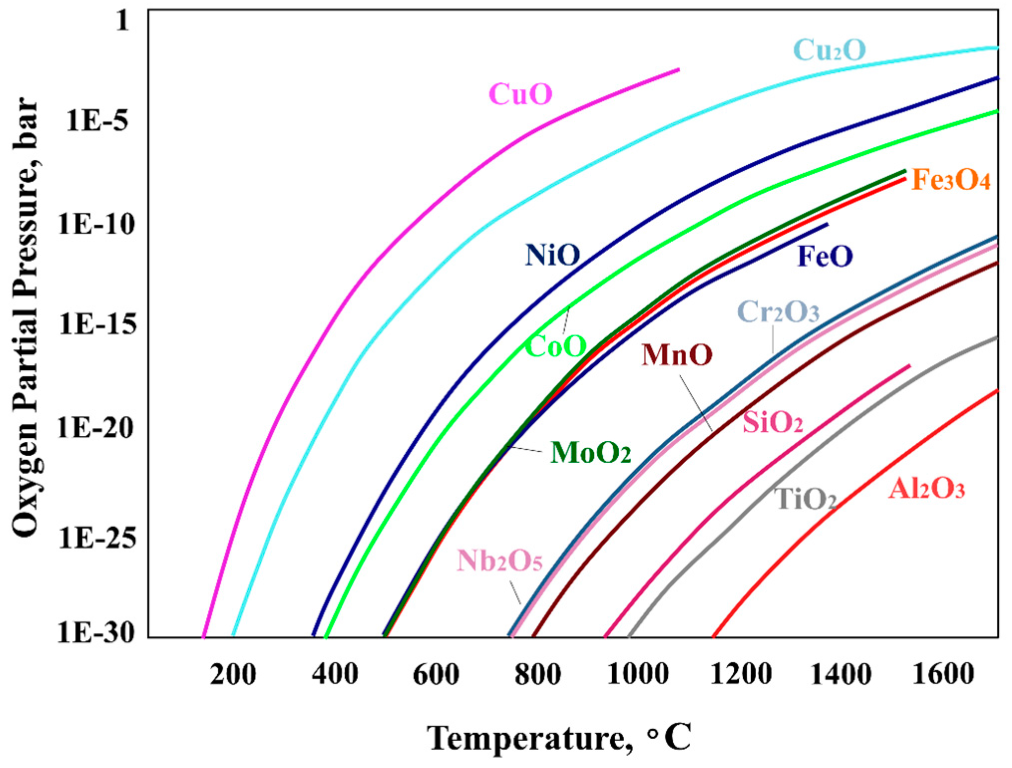
The presence of elements with high oxygen affinities in superalloys leads to the production of highly stable oxides at the powder surface, or so-called PPB, in the consolidated products. The effects of PPBs are known to have detrimental effects on the mechanical properties of HIP materials. If the amount of oxygen is limited, the formation of Al2O3 and TiO2 is expected to occur first, before the other elements are oxidized, due to the order of Gibbs energies for the oxides [27,28] (see Figure 14). These oxides would promote the subsequent precipitation of MC-type carbides or M23C6-type carbides along the PPB (Figure 7). These oxides act as heterogeneous nuclei sites, which have a strong effect on the nucleation and growth behavior of the carbide. During the heat-treatment process, carbide-forming elements within the powder would migrate to the specific oxides of particle surfaces, resulting in stable oxy-carbides on the PPB [24].
4.3. The Effects of PPB on the Mechanical Properties of HIP Specimens at 650 °C
The strengths and ductility of the SLM + STA specimen were comparable to those of the conventionally wrought specimen, both at room temperature and 650 °C, as shown in Table 2 and Table 3. However, a drop was observed in the ductility of HIP + STA material at 650 °C (Table 3). The fracture surfaces appeared completely along the PPB (Figure 11c). The presence of a PPB decorated with brittle oxide and carbide particles resulted in premature failure [11,29]. The degree of ductility of a material is related to the relaxation process that occurs at the crack-tip. When brittle non-metallic particles which tend to lead to interface decohesion are dispersed along the boundaries of the matrix content [30], such as carbides or oxides along the PPB in HIP materials, the process of crack nucleation at the grain boundary takes place more easily at 650 °C. Due to the interface between incoherent particles, the matrix becomes a preferred site for crack initiation [23]. The crack would begin to propagate rapidly when the stress reaches a critical value. The presence and specific location of the precipitates along the PPB weaken the metallic bonding between two adjacent powders, which leads to worse mechanical properties [31], contributing to the predominance of fractures along the PPB in HIP materials at 650 °C (Figure 11).
Interestingly, the HIP + STA material strengthened by precipitation showed only one-seventh of the ductility shown by the as-HIPed specimen at 650 °C (Table 3). The drop in the ductility of the HIP + STA material was observed under both the tensile test and creep test at 650 °C. As the temperature increases above 750 °C, the coherent relationship between γ and γ″ could be lost and be replaced by the incoherent δ phase with the same Ni3Nb composition [16]. The γ″ phase will be metastable, and the conversion reaction of γ/γ″ → δ accelerates at temperatures above 750 °C [32]. These needle-shaped and brittle δ phases are generally undesirable due to their adverse effects on mechanical properties [33], which lead to “δ-phase embrittlement” [16,34] (Figure 12). Furthermore, the previous oxides along the PPB would promote the subsequent precipitation of carbides along the PPB (Figure 7). During the heat-treatment process, carbide-forming elements within the powder would migrate to the specific oxides of particle surfaces, resulting in stable oxy-carbides on the PPB [24]. The carbides would grow during the heat-treatment process, which includes enough diffusion time for the required carbide-forming elements to be obtained (Figure 7a,b). These script-like carbides or needle-shaped δ phases generally would have a negative effect on alloy performance. Since the oxides, carbides and needle-shaped δ phases are closely spaced along the PPB (Figure 7a), they provide a continuous path for crack propagation. At temperatures above 980 °C, Al2O3 forms as a protective oxide scale [35]. After one hour of isothermal oxidation in CM-247LC, continuous Al2O3 formed at 1150 °C, whereas, NiO formed at 1000 °C [36]. This means that the HIP temperature of 1180 °C would be suitable for forming Al2O3 in Ni-based superalloys. The main reason for this is that PPB precipitate networks formed during HIPing would be maintained at the HIP temperature for a long time (Figure 3a). As a result, the HIP + STA material would exhibit premature fracturing with poor ductility at 650 °C.
4.4. Free-PPB Microstructure in SLM Materials
Precipitates were localized along the PPB in both the as-HIPed and HIP + STA specimens (Figure 1), whereas SLM materials showed a free-PPB microstructure despite having a comparable oxygen content (Table 1). The difference in microstructure can be explained as follows. The HIP process is a solid-state diffusion process occurring below the material’s melting temperature. The presence in superalloys of elements with high oxygen affinities brings about highly stable oxides at the powder surface. These oxides along the PPB would become diffusion barriers, resulting in a slower diffusion process [37]. As for the SLM process, the laser beam irradiates metallic powder in order to form a layer-by-layer material in a chamber with an inert gas atmosphere. The main reason that limited oxides are observed would be that the precipitates along the PPB precipitates network are churned and spread uniformly. Another layer of metallic powder is then fused and deposited, and the previous layer absorbs the extra power, resulting in the remelting of a part of the previous layer [26]. This remelting process is analogous to dilution, which provides a continuous solid–liquid interface free of contaminants or oxides and a sufficient bonding between layers [26,38,39]. Furthermore, the evaporation of Al and the ejection of pure-Al-rich particles with only 0.4 wt % oxygen were observed during the SLM process [40]. These results show that Al is easy to vaporize, and that Al2O3 does not easily form during the SLM process because the time exposed to high temperatures above 1150 °C is limited (Figure 3b). From the view point of thermodynamics, Figure 14 shows the equilibrium oxygen partial pressure for some metal oxides/metal systems [28]. Figure 14 clearly indicates that every oxide could be avoided when the optimal temperature and oxygen partial pressure are reached. Under the conditions below each curve in the figure (low oxygen partial pressure and high temperature), the oxide is decomposed. On the other hand, above each curve (i.e., under high oxygen partial pressure and low temperature conditions) the metal is easily oxidized [28]. In the current study, since the temperature was maintained in the HIP process (1180 °C for 4 h), a certain degree of oxidation cannot be avoided under normal HIP conditions. HIP was performed in a chamber with a vacuum which contained contaminants in the form of water and oxygen. As a result, metals could be easily oxidized during the HIP process (Figure 3a and Figure 14). On the other hand, the minimum temperature in a high-energy laser-beam-focused zone ranges from 1260 to 1336 °C (melting point of Alloy718) during the SLM process [35]. As a result of the decomposition of contaminant compounds, such compounds might appear at low density in SLM materials (Figure 1 and Figure 5).
5. Conclusions
The following conclusions can be drawn from this work:
- (1)
- Continuous precipitates were clearly localized along the PPB in HIP materials, while SLM materials showed a microstructure free of PPBs and an extremely low number of contaminants.
- (2)
- The columnar grains in the SLM specimens were attributed to epitaxial growth.
- (3)
- The strengths and ductilities of the SLM + STA specimen were comparable to those of the conventionally wrought specimen both at room temperature and 650 °C. However, a drop was observed in the ductility of the HIP material at 650 °C.
- (4)
- The brittle precipitates formed in the HIP materials, such as oxy-carbides and δ phases, tended to lead to interface decohesion and resulted in premature fracture with poor ductility at 650 °C.
- (5)
- The main reason that PPB precipitate networks formed during HIPing is that the HIP temperature was held at a temperature suitable for forming Al2O3 for a long time.
- (6)
- In the SLM process, Al2O3, which became a nucleation site of precipitates, is not easily formed, and the PPB precipitates network is churned and spread uniformly during the process.
Acknowledgments
This research was supported by the ALCA Program of the Japan Science and Technology Agency, JST, and a Grant-in-Aid for Scientific Research (16K06799) from the Japan Society for the Promotion of Science. This support is gratefully acknowledged.
Author Contributions
Yen-Ling Kuo performed the experiments, analyzed the data and wrote the paper; Koji Kakehi designed the experiments and wrote the paper.
Conflicts of Interest
The authors declare no conflict of interest.
References
- Yeh, A.C.; Lu, K.W.; Kuo, C.M.; Bor, H.Y.; Wei, C.N. Effect of serrated grain boundaries on the creep property of Inconel 718 superalloy. Mater. Sci. Eng. A 2011, 530, 525–529. [Google Scholar] [CrossRef]
- Chamanfar, A.; Sarrat, L.; Jahazi, M.; Asadi, M.; Weck, A.; Koul, A.K. Microstructural characteristics of forged and heat treated Inconel-718 disks. Mater. Des. 2013, 52, 791–800. [Google Scholar] [CrossRef]
- Ghosh, S.; Yadav, S.; Das, G. Study of standard heat treatment on mechanical properties of Inconel 718 using ball indentation technique. Mater. Lett. 2008, 62, 2619–2622. [Google Scholar] [CrossRef]
- Bai, Q.; Lin, J.; Tian, G.; Dean, T.A.J. Review and analysis of powder prior boundary (PPB) formation in powder metallurgy processes for nickel-based super alloys. J. Powder Metall. Min. 2015, 4. [Google Scholar] [CrossRef]
- Lee, S.C.; Chang, S.H.; Tang, T.P.; Ho, H.H.; Chen, J.K. Improvement in the microstructure and tensile properties of Inconel 718 superalloy by HIP treatment. Mater. Trans. 2006, 47, 2877–2881. [Google Scholar] [CrossRef]
- Rao, G.A.; Kumar, M. High performance stainless steel via powder metallurgy hot isostatic pressing. Mater. Sci. Technol. 1997, 13, 1027–1031. [Google Scholar] [CrossRef]
- Gessinger, G.H. Powder Metallurgy of Superalloys; Butteriworth & Co.: London, UK, 1984. [Google Scholar]
- Maurer, G.E.; Castledine, W.; Schweizer, F.A.; Mancuso, S. Development of HIP consolidated P/M superalloys for conventional forging to gas turbine engine components. In Proceedings of the 8th International Symposium on Superalloys, Pittsburgh, PA, USA, 28 September–1 October 2014; pp. 645–652. [Google Scholar]
- Furrer, D.; Fecht, H. Ni-based superalloys for turbine discs. JOM 1999, 51, 14–17. [Google Scholar] [CrossRef]
- Rao, G.A.; Srinivas, M.; Sarma, D.S. Effect of solution treatment temperature on microstructure and mechanical properties of hot isostatically pressed superalloy Inconel* 718. Mater. Sci. Technol. 2004, 20, 1161–1170. [Google Scholar] [CrossRef]
- Bai, Q.; Lin, J.; Jiang, J.; Dean, T.A.; Zou, J.; Tian, G. A study of direct forging process for powder superalloys. Mater. Sci. Eng. A 2015, 621, 68–75. [Google Scholar] [CrossRef]
- Haase, C.; Bültmann, J.; Hof, J.; Ziegler, S.; Bremen, S.; Hinke, C.; Schwedt, A.; Prahl, U.; Bleck, W. Exploiting process-related advantages of selective laser melting for the production of high-manganese steel. Materials 2017, 10, 56. [Google Scholar] [CrossRef] [PubMed]
- Ellyson, B.; Brochu, M.; Brochu, M. Characterization of bending vibration fatigue of SLM fabricated Ti-6Al-4V. Int. J. Fatigue 2011, 19, 389–395. [Google Scholar] [CrossRef]
- AlMangour, B.; Grzesiakc, D.; Yang, J.M. Selective laser melting of TiB2/H13 steel nanocomposites: Influence of hot isostatic pressing post-treatment. J. Mater. Process. Technol. 2017, 244, 344–353. [Google Scholar] [CrossRef]
- Kuo, Y.L.; Horikawa, S.; Kakehi, K. The effect of interdendritic δ phase on the mechanical properties of Alloy 718 built up by additive manufacturing. Mater. Des. 2017, 116, 411–418. [Google Scholar] [CrossRef]
- Kuo, Y.L.; Horikawa, S.; Kakehi, K. Effects of build direction and heat treatment on creep properties of Ni-base superalloy built up by additive manufacturing. Scr. Mater. 2017, 129, 74–78. [Google Scholar] [CrossRef]
- Donachie, M.J.; Donachie, S.J. Superalloys: A Technical Guide, 2nd ed.; ASM International: Geauga County, OH, USA, 2002. [Google Scholar]
- Zhang, J.; Singer, R.F. Hot tearing of nickel-based superalloys during directional solidification. Acta Mater. 2002, 50, 1869–1879. [Google Scholar] [CrossRef]
- Chang, S.; Lee, S.; Tang, T.; Ho, H. Influences of soaking time in hot isostatic pressing on strength of inconel 718 superalloy. Mater. Trans. 2006, 47, 426–432. [Google Scholar] [CrossRef]
- Jia, Q.; Gu, D. Selective laser melting additive manufacturing of Inconel 718 superalloy parts: Densification, microstructure and properties. J. Alloys Compd. 2014, 585, 713–721. [Google Scholar] [CrossRef]
- Zhang, B.; Lee, X.; Bai, J.; Guo, J.; Wang, P.; Sun, C.; Nai, M.; Qi, G.; Wei, J. Study of selective laser melting (SLM) Inconel 718 part surface improvement by electrochemical polishing. Mater. Des. 2017, 116, 531–537. [Google Scholar] [CrossRef]
- Kanagarajah, P.; Brenne, F.; Niendorf, T.; Maier, H.J. Inconel939 processed by selective laser melting: Effect of microstructure and temperature on the mechanical properties under static and cyclic loading. Mater. Sci. Eng. A 2013, 588, 188–195. [Google Scholar] [CrossRef]
- Rao, G.A.; Kumar, M.; Srinivas, M.; Sarma, D.S. Effect of standard heat treatment on the microstructure and mechanical properties of hot isostatically pressed superalloy inconel 718. Mater. Sci. Eng. A 2003, A355, 114–125. [Google Scholar] [CrossRef]
- Crompton, J.S.; Hertzberg, R.W. Analysis of second phase particles in a powder metallurgy HIP nickel-base superalloy. J. Mater. Sci. 1986, 21, 3445–3454. [Google Scholar] [CrossRef]
- Olakanmi, E.O.; Cochrane, R.F.; Dalgarno, K.W. A review on selective laser sintering/melting (SLS/SLM) of aluminium alloy powders: Processing, microstructure, and properties. Prog. Mater. Sci. 2015, 74, 401–477. [Google Scholar] [CrossRef]
- DuPont, J.N.; Lippold, J.C.; Kiser, S.D. Welding Metallurgy and Weldability of Nickel Base Alloys; John Wiley & Sons, Inc.: Hoboken, NJ, USA, 2009. [Google Scholar]
- He, L.M.; Su, Y.-F.; Allard, L.F.; Lance, M.J.; Lee, W.Y. Effects of preoxidation on the nucleation and growth behavior of chemically vapor-deposited α-Al2O3 on a single-crystal Ni-based superalloy. Metall. Trans. A 2004, 35, 1113–1124. [Google Scholar] [CrossRef]
- Hryha, E.; Dudrova, E.; Nyborg, L. On-line control of processing atmospheres for proper sintering of oxidation-sensitive PM steels. J. Mater. Process. Technol. 2012, 212, 977–987. [Google Scholar] [CrossRef]
- Wallace, W.; Wiebe, W.; Whelan, W.P.; Dainty, R.V.; Terada, T. The effect of grain-boundary structure on the tensile fracture behavior of hot-isostatically pressed 713 LC Alloy Compacts. Powder Metall. 1972, 16, 416–435. [Google Scholar] [CrossRef]
- Tetelman, A.S.; Mcevily, A.J., Jr. Fracture of Structural Materials; John Wiley & Sons Inc.: New York, NY, USA, 1967; pp. 193–233. [Google Scholar]
- Broek, D. Elementary Engineering Fracture Mechanics; Martinus Nijhoff: Leiden, The Netherlands, 1984. [Google Scholar]
- Idell, Y.; Levine, L.E.; Allen, A.J.; Zhang, F.; Campbell, C.E.; Olson, G.B.; Gong, J.; Snyder, D.R.; Deutchman, H.Z. Unexpected δ-phase formation in additive-manufactured Ni-based superalloy. JOM 2016, 68, 950–959. [Google Scholar] [CrossRef]
- Campo, E.; Turco, C.; Catena, V. The correlation between heat treatment, structure and mechanical characteristics in Inconel 718. Metall. Sci. Technol. 1985, 3, 16–21. [Google Scholar]
- Radavich, J.F.; Korth, G.E.; Antolovich, S.D.; Stusrud, R.W.; MacKay, R.A.; Khan, T.; Kissinger, R.D.; Klarstrom, D.L. High temperature degradation of Alloy 718 after longtime exposures. In Proceedings of the 7th International Symposium on Superalloys, Seven Springs, PA, USA, 20–24 September 1992; pp. 497–506. [Google Scholar]
- Davis, J.R. ASM Specialty Handbook: Heat-Resistant Materials; ASM International: Geauga County, OH, USA, 1997. [Google Scholar]
- Chiou, M.S.; Jian, S.R.; Yeh, A.C.; Kuo, C.M. Effects of aluminum addition on the high temperature oxidation behavior of CM-247LC Ni-based superalloy. Int. J. Electrochem. Sci. 2015, 10, 5981–5993. [Google Scholar]
- German, R. Powder Metallurgy and Particulate Materials Processing: The Processes, Materials, Products, Properties and Applications; Metal Powder Industries Federation: Princeton, NJ, USA, 2005. [Google Scholar]
- Abe, F.; Osakada, K.; Shiomi, M.; Matsumoto, M.; Shiomi, M. The manufacturing of hard tools from metallic powders by selective laser melting. J. Mater. Process. Technol. 2001, 111, 210–213. [Google Scholar] [CrossRef]
- Das, S.; Beaman, J.J. Direct Selective Laser Sintering of Metals. U.S. Patent 6,676,892 B2, 13 January 2004. [Google Scholar]
- Wang, X.; Read, N.; Carter, L.N.; Ward, R.M.; Attallah, M.M. Defect formation and mitigation in selective laser melting of high γ′ Ni-base superalloys. In Proceedings of the 13th International Symposium on Superalloys, Seven Springs, PA, USA, 11–15 September 2016; pp. 351–358. [Google Scholar]
Figure 1.
Secondary electron (SE) images of gas-atomized IN718 powders used for (a) hot isostatic pressing (HIP) and (b) selective laser melting (SLM); SE images of (c) particles along the prior particle boundary (PPB) in an as-HIPed specimen and (d) an as-built SLM specimen.
Figure 1.
Secondary electron (SE) images of gas-atomized IN718 powders used for (a) hot isostatic pressing (HIP) and (b) selective laser melting (SLM); SE images of (c) particles along the prior particle boundary (PPB) in an as-HIPed specimen and (d) an as-built SLM specimen.
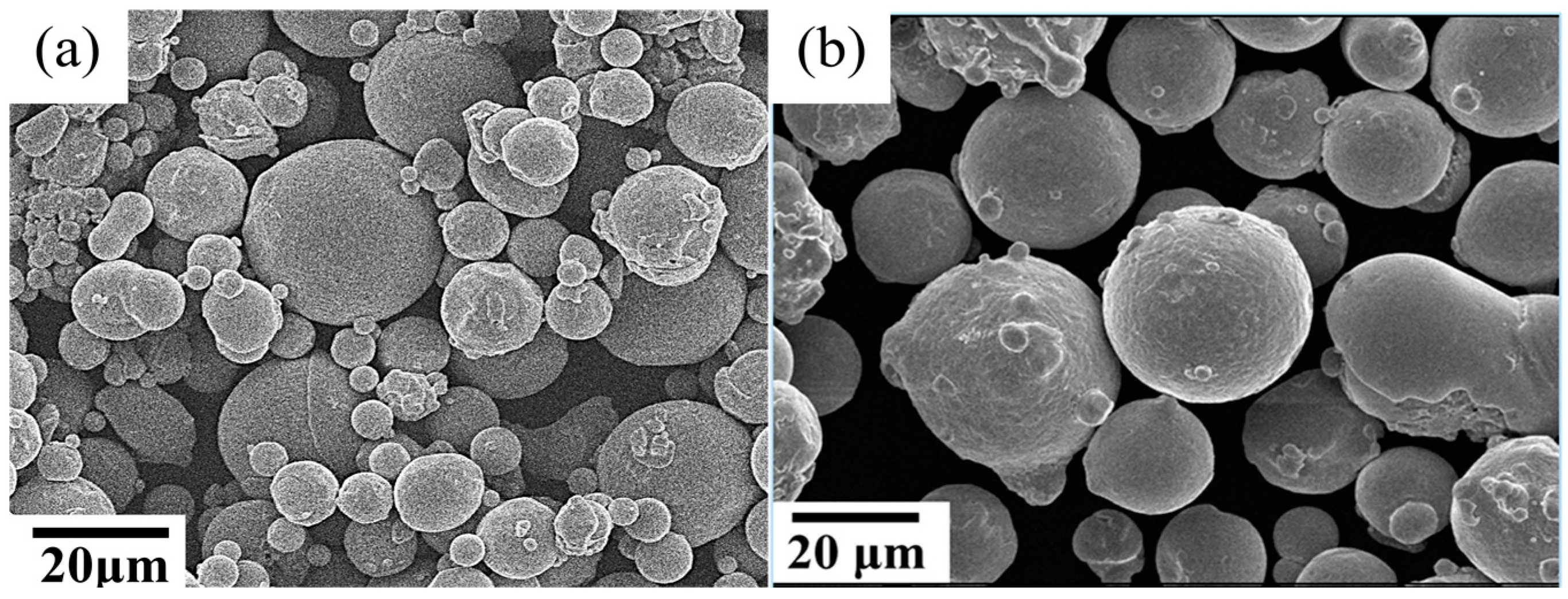

Figure 2.
Illustrations of (a) scanning strategy of the SLM process and (b) dimensions of the mechanical test specimen (mm).
Figure 2.
Illustrations of (a) scanning strategy of the SLM process and (b) dimensions of the mechanical test specimen (mm).

Figure 3.
Heat history of the (a) HIP process and (b) SLM process.

Figure 4.
X-ray diffraction (XRD) patterns of as-HIPed and as-built SLM samples.

Figure 5.
Transmission electron microscopy (TEM) bright field micrograph of (a) as-HIPed specimen and (b) as-built SLM specimen; Digital maps of energy dispersive spectroscopy (EDS) analysis showing distribution of Al, O, Ti and Nb elements within (c) as-HIPed specimen and (d) as-built SLM specimen.

Figure 6.
Inverse pole figures (IPFs) of (a) as-HIPed; (b) as-built SLM; (c) HIP + solution treatment and aging (HIP + STA) and (d) SLM + STA specimens were analyzed using the orientation measurements by electron backscatter diffraction (EBSD).
Figure 6.
Inverse pole figures (IPFs) of (a) as-HIPed; (b) as-built SLM; (c) HIP + solution treatment and aging (HIP + STA) and (d) SLM + STA specimens were analyzed using the orientation measurements by electron backscatter diffraction (EBSD).

Figure 7.
TEM bright field micrographs of (a) particles along the PPB; (b) growth behavior of oxy-carbides; (c) EDS digital maps showing the distribution of elements within the HIPed material after the heat-treatment process.
Figure 7.
TEM bright field micrographs of (a) particles along the PPB; (b) growth behavior of oxy-carbides; (c) EDS digital maps showing the distribution of elements within the HIPed material after the heat-treatment process.

Figure 8.
Engineering stress-strain curves of HIP specimen and SLM specimens at room temperature.

Figure 9.
Engineering stress-strain curves of HIP specimen and SLM specimens at 650 °C.
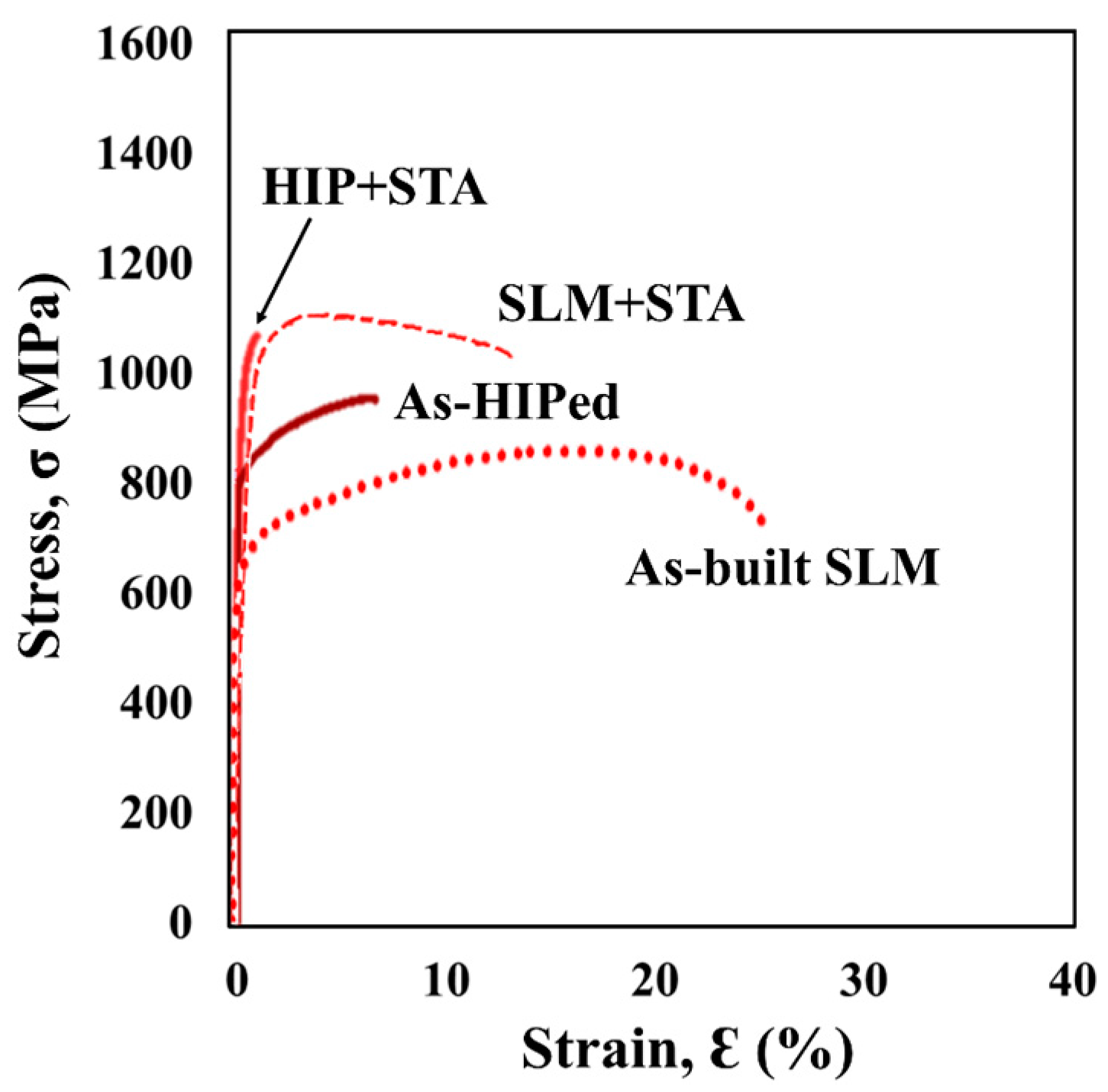
Figure 10.
TEM bright field micrograph of strengthening phase precipitate within (a) HIP + STA and (b) SLM + STA specimens and (c) high magnification of area I in (b).
Figure 10.
TEM bright field micrograph of strengthening phase precipitate within (a) HIP + STA and (b) SLM + STA specimens and (c) high magnification of area I in (b).

Figure 11.
Fracture surfaces of (a) HIP + STA specimen and (b) SLM + STA specimen tested at room temperature; fracture surfaces of (c) HIP + STA specimen and (d) SLM + STA specimen tested at 650 °C.
Figure 11.
Fracture surfaces of (a) HIP + STA specimen and (b) SLM + STA specimen tested at room temperature; fracture surfaces of (c) HIP + STA specimen and (d) SLM + STA specimen tested at 650 °C.
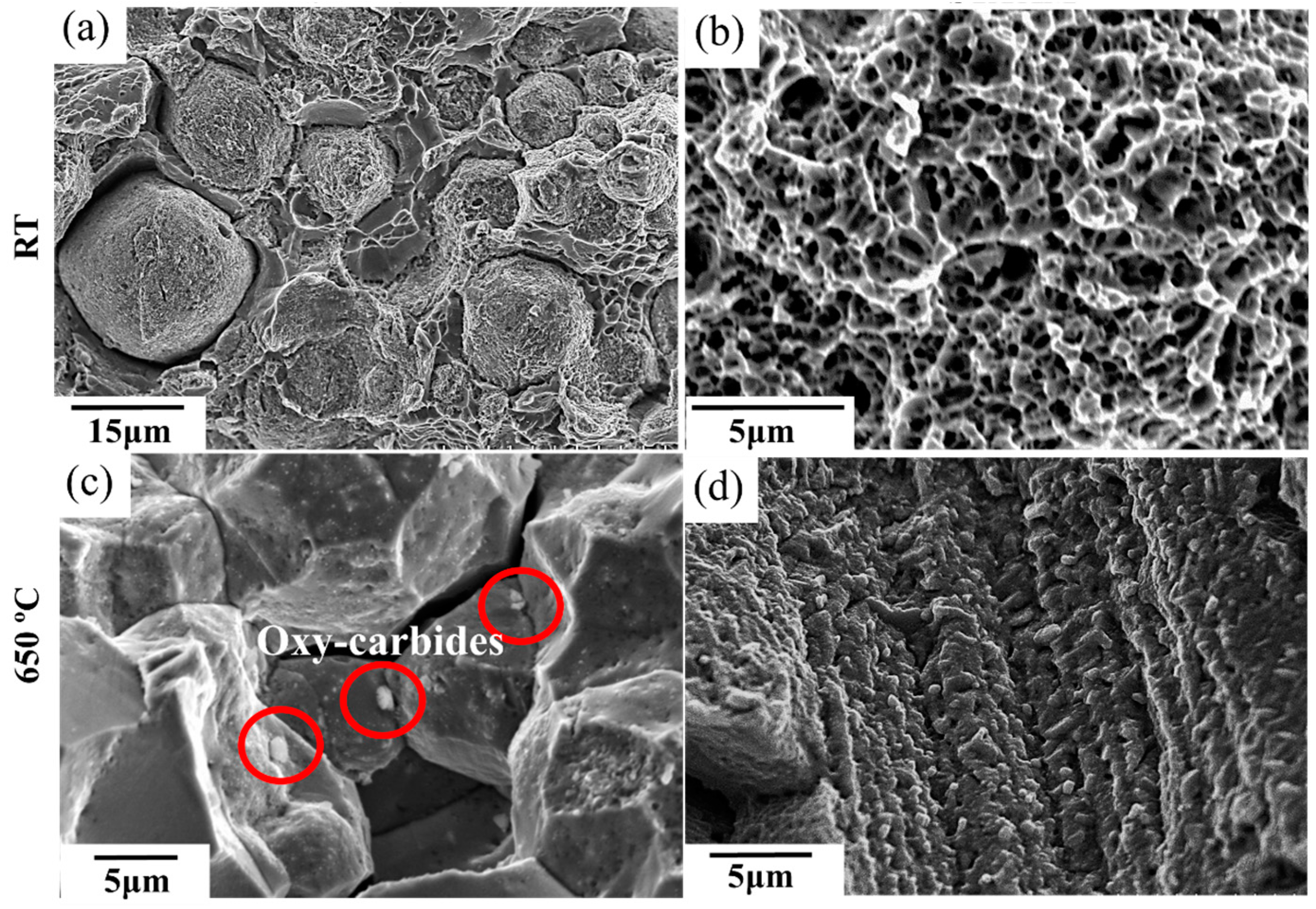
Figure 12.
Creep curves of HIP + STA specimen and SLM + STA at 650 °C and 550 MPa.

Figure 13.
Fracture surfaces of (a) HIP + STA specimen and (d) SLM + STA specimen tested at 650 °C and 550 MPa.
Figure 13.
Fracture surfaces of (a) HIP + STA specimen and (d) SLM + STA specimen tested at 650 °C and 550 MPa.
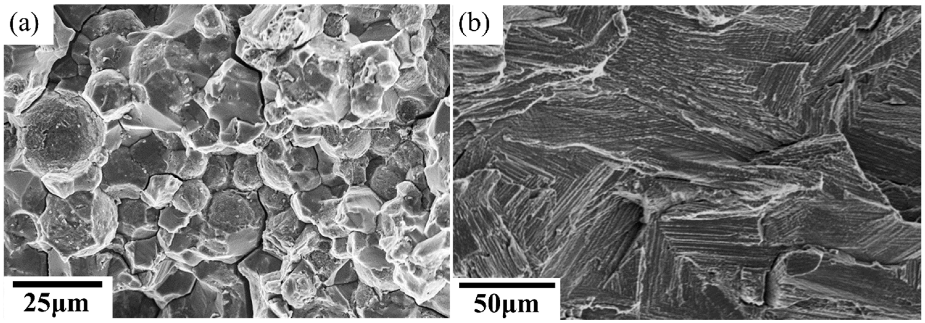
Figure 14.
Illustration of equilibrium oxygen partial pressure for some metal oxides/metal systems, reproduced with permission from [28]. Elsevier, 2012.
Figure 14.
Illustration of equilibrium oxygen partial pressure for some metal oxides/metal systems, reproduced with permission from [28]. Elsevier, 2012.


Table 1.
Chemical composition of IN718 powder used in HIP and SLM (mass %).
| IN718 | Cr | Nb | Mo | Ti | Al | Co | Cu | C | Si, Mn | P, S | B | O | Fe | Ni |
|---|---|---|---|---|---|---|---|---|---|---|---|---|---|---|
| HIP | 18.4 | 4.98 | 3.3 | 0.84 | 0.57 | 0.1 | 0.01 | 0.026 | 0.08 | 0.02 | 0.001 | 0.014 | 17.2 | Bal. |
| SLM | 19.6 | 5.05 | 2.85 | 1.10 | 0.46 | 0.03 | 0.05 | 0.04 | 0.04 | 0.0 | 0.002 | 0.019 | Bal. | 52.59 |
Table 2.
Tensile properties at room temperature.
| σ0.2 (MPa) | σT (MPa) | εf (%) | |
|---|---|---|---|
| As-HIPed | 833 | 1225 | 32.1 |
| As-built SLM | 677 | 1023 | 28.1 |
| HIP + STA | 1125 | 1473 | 21.2 |
| SLM + STA | 1271 | 1425 | 18.6 |
| Wrought + STA | 1216 | 1435 | 24.0 |
Table 3.
Tensile properties at 650 °C.
| σ0.2 (MPa) | σT (MPa) | εf (%) | |
|---|---|---|---|
| As-HIPed | 844 | 978.0 | 6.8 |
| As-built SLM | 594 | 862.0 | 25.1 |
| HIP + STA | 1031 | 1093 | 0.9 |
| SLM + STA | 1042 | 1142 | 10.1 |
| Wrought + STA | 1028 | 1139 | 10.5 |
© 2017 by the authors. Licensee MDPI, Basel, Switzerland. This article is an open access article distributed under the terms and conditions of the Creative Commons Attribution (CC BY) license (http://creativecommons.org/licenses/by/4.0/).
Share and Cite
MDPI and ACS Style
Kuo, Y.-L.; Kakehi, K. Influence of Powder Surface Contamination in the Ni-Based Superalloy Alloy718 Fabricated by Selective Laser Melting and Hot Isostatic Pressing. Metals 2017, 7, 367. https://doi.org/10.3390/met7090367
AMA Style
Kuo Y-L, Kakehi K. Influence of Powder Surface Contamination in the Ni-Based Superalloy Alloy718 Fabricated by Selective Laser Melting and Hot Isostatic Pressing. Metals. 2017; 7(9):367. https://doi.org/10.3390/met7090367
Chicago/Turabian StyleKuo, Yen-Ling, and Koji Kakehi. 2017. "Influence of Powder Surface Contamination in the Ni-Based Superalloy Alloy718 Fabricated by Selective Laser Melting and Hot Isostatic Pressing" Metals 7, no. 9: 367. https://doi.org/10.3390/met7090367
Note that from the first issue of 2016, this journal uses article numbers instead of page numbers. See further details here.