An Eco-Friendly Neutralization Process by Carbon Mineralization for Ca-Rich Alkaline Wastewater Generated from Concrete Sludge

Center for Carbon Mineralization, Climate Change Mitigation and Sustainability Division, Korea Institute of Geoscience and Mineral Resources (KIGAM), 124 Gwahak-ro, Yuseong-gu, Daejeon 34132, Korea
*
Author to whom correspondence should be addressed.
Metals 2017, 7(9), 371; https://doi.org/10.3390/met7090371
Submission received: 28 July 2017
/
Revised: 11 September 2017
/
Accepted: 11 September 2017
/
Published: 13 September 2017
(This article belongs to the Special Issue Valuable Metal Recycling)
Abstract
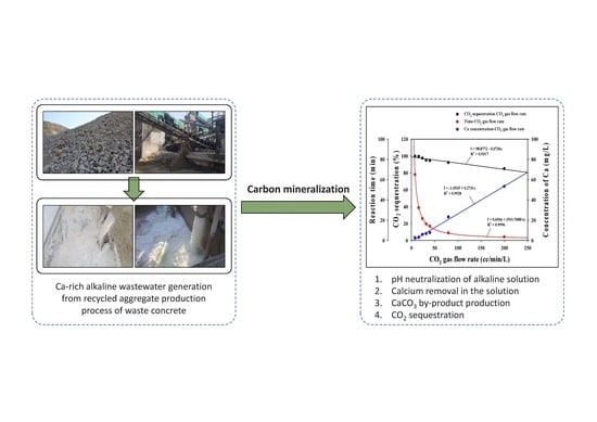
:Waste-concrete recycling processes using wet-based crushing methods inevitably generate a large amount of alkaline concrete sludge, as well as wastewater, which contains abundant Ca ions. The Ca-rich alkaline wastewater must then be neutralized for reuse in the waste-concrete recycling process. In this study, the feasibility of a carbon mineralization process for the neutralization of alkaline wastewater was considered from both environmental and economic perspectives. The optimal reaction time, efficiency of Ca removal and CO2 sequestration as a function of the CO2 gas flow rate were assessed. The carbon mineralization process resulted in sequestering CO2 (85–100% efficiency) and removing Ca from the solution (84–99%) by precipitating pure CaCO3. Increasing the gas flow rate reduced the reaction time (65.0 down to 3.4 min for 2.5 L of solution), but decreased CO2 sequestration (from 463.3 down to 7.3 mg CO2 for 2.5 L of solution). Optimization of the gas flow rate is essential for efficient CO2 sequestration, Ca removal, CaCO3 production and, therefore, successful wastewater neutralization following the wet-based crushing process. The method presented here is an eco-friendly and economically viable substitute for dealing with alkaline wastewater. It may also provide a practical guide for the design of carbon mineralization processes for the neutralization of alkaline solutions containing large amounts of Ca.
1. Introduction
The amount of construction waste produced in Korea increases yearly due to the significant number of aged buildings requiring re-construction. Shortages in raw materials and available landfill sites mean an improvement in construction waste recycling is required [1]. Currently, waste concrete accounts for approximately 63% of construction waste; a total of 198,000 tons generated per day. As a result, more than 95% of waste concrete is used as aggregate material in new concrete [2,3]. In the intermediate-construction waste recycling process, crushing and screening produces a large amount of concrete sludge composed of fine-grained concrete material. Water is used to wash down the concrete surface and separate impurities [4].
This study assessed the recycling process of a local waste-concrete treatment plant. The wet-based crushing method consisted of crushing/screening, classifying and flocculating concrete fines, as illustrated in Figure 1. Dried sludge, precipitated using cationic-organic polymer coagulants was discarded at a rate of 10 tons/day. The total amount of solid phase included in the concrete sludge from recycled concrete-aggregate production was approximately 7%, increasing up to 40% for high quality aggregate products.
The concrete sludge was strongly alkaline and rich in calcium (Ca) as a result of calcium hydroxide (Ca(OH)2) dissolution from the concrete particles [5]. The air-dried solids, generated from the solid-liquid separation and flocculation process, were discarded as they were considered to have insignificant economic value. The supernatant from the flocculation process was reused in the wet-based crushing processes, without further treatment. The best practice, from both environmental and economic stand points, should include neutralization for discharge into streams or, ideally, neutralization and reuse to remove cement paste in the wet process of waste concrete production. Treatment using sulfuric acid (H2SO4) is commonly employed to neutralize alkaline wastewater, because of the simplicity of the process. However, it does increases the agent cost consumption [6]. This added cost is a significant barrier to the development of the whole waste-concrete recycling process. In addition, neutralization of the wastewater using acids, without Ca removal, is not effective in removing cement paste from the aggregates in the waste-concrete recycling process due to the over-saturation of Ca.
Since the Kyoto Protocol in 1997, countries of the world have been actively working to reduce carbon dioxide (CO2) emissions, which are emitted from power plants and industry [7,8]. Among possible strategies for reducing atmospheric CO2 concentrations, carbon capture utilization and sequestration (CCUS) technologies are the most available and widely-applied strategies [9]. The carbon mineralization process is an attractive carbonate-based mineral production technique for industries. In addition, it is also a CO2 sequestration technique to reduce CO2 atmospheric levels through the consumption of flue gas [10]. It also neutralizes alkaline solutions [8,11,12] and results in the production of useful carbonate-based minerals such as calcium carbonate (CaCO3). The carbon mineralization process in a Ca-rich solution occurs according to the following Reactions (1)–(4) [13,14,15,16,17].
CO2(g) → CO2(aq) CO2 solvation
CO2(aq) + H2O ↔ H2CO3(aq) ↔ HCO3− + H+ ↔ 2H+ + CO32− CO2 dissociation (carbonation)
Ca(OH)2(s) ↔ Ca2+ + 2(OH)− Ca(OH)2 dissolution
Ca2+ + 2(OH)− + 2H+ + CO32− → CaCO3(s) + 2H2O Carbon mineralization
In aqueous solution, protons and carbonate ions are generated through dissociation of CO2 (Equations (1) and (2)). The dissolution of Ca(OH)2 in concrete by the solubility product constant (Ksp of Ca(OH)2 = 5.5 × 10⁻⁶) results in several alkaline solutions (approximately pH 12.6) and Ca saturation in solution (approximately 800 mg/L) according to Equation (3). In the field plant, the solution pH and Ca concentration conditions could fluctuate on a daily basis. Protons produced in the carbon mineralization process can be very effective in neutralizing alkaline solution from concrete sludge. In addition, CaCO3 by-products produced by this process can be used in other industries for cement production, paper filling/coating additives and plastic/paint manufacturing according to purity and varying particle sizes [18,19]. Numerous studies have been undertaken recently on the carbon mineralization processes using Ca-rich alkaline solution from various sources, focusing on the production and characterization of CaCO3 particles (e.g., rhombic calcite, orthorhombic aragonite, spherical vaterite; µ-CaCO3) [15,20,21,22,23].
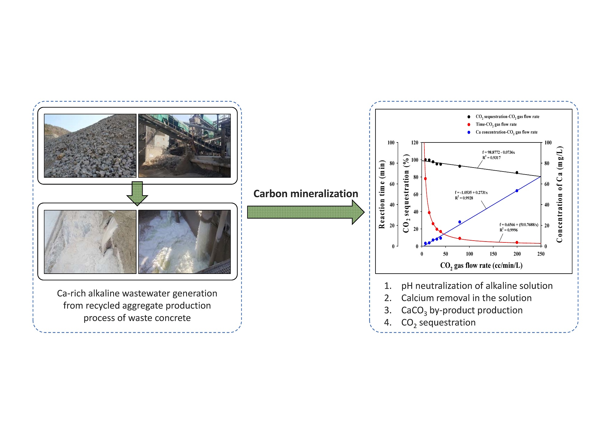
In comparison, this study focuses on the development of an eco-friendly, alkaline wastewater neutralization process without the use of acids. It was designed to sequester CO2 with CaCO3 and to recycle the neutralized water through the carbon mineralization process in wet-based crushing procedures. To this end, a laboratory-scale carbon mineralization process was designed to neutralize wastewater generated from concrete sludge during the waste concrete recycling process (Figure 2). The neutralized water, from which Ca ions were removed, is expected to be effectively recycled to remove the cement paste absorbed into aggregate surfaces in the wet-based crushing/screening of the waste-concrete recycling process.
2. Materials and Methods
2.1. Characterization of Concrete Sludge
Approximately 3600 m3 of concrete sludge and wastewater are generated daily through the wet-based crushing/screening process. The concrete sludge sample used in this study was collected from a field construction waste treatment plant (CWTP) in Incheon, Korea. Sludge moisture content was analyzed by weight loss with oven-drying at 105 °C until the weight did not change. The pH and electrical-conductivity (EC) of the sludge were measured using calibrated pH (ORION VSTAR-PH, Thermo Fisher Scientific Inc., Waltham, MA, USA) and EC meters (HQ40d, HACH, Loveland, CO, USA). The sludge particles were separated according to Korean Standard Testing Method (KS F 2309) based on wet sieving using 70, 100, 200, 325 and 400 mesh, with sludge solution instead of fresh water used to avoid further dissolution of minerals such as Ca(OH)2. The particle size distribution was determined by weight loss at 105 °C for 24 h after separation by wet sieving. Significant impurities were present in the less than 70 mesh sieve fraction (0.212 mm), so the collected sludge was further separated by vacuum filtration using filter papers with a pore size of 0.45 µm. After filtration, the liquid phase was kept at room temperature to prevent precipitation of natural CaCO3 through a reaction between Ca in solution and atmospheric CO2. The residual solids were completely dried at 105 °C for 24 h. The concentrations of aqueous Ca, K and Na were measured with an inductively-coupled plasma optical emission spectrometer (ICP-OES, Agilent, 720-ES, Santa Clara, CA, USA). The qualitative and quantitative analysis of sludge particle mineralogy was performed by X-ray diffraction (XRD, Philips, X’pert MPD, Almelo, The Netherlands). The chemical composition of the sludge was measured by X-ray fluorescence (XRF, MXF-2400, Shimadzu, Kyoto, Japan). The XRD and XRF analyses were performed on oven-dried samples sieved through 200 mesh (0.075 mm) after vacuum filtration and pulverization with a mortar and pestle.
2.2. Carbon Mineralization
2.2.1. Apparatus of the Carbon Mineralization Processing Reactor
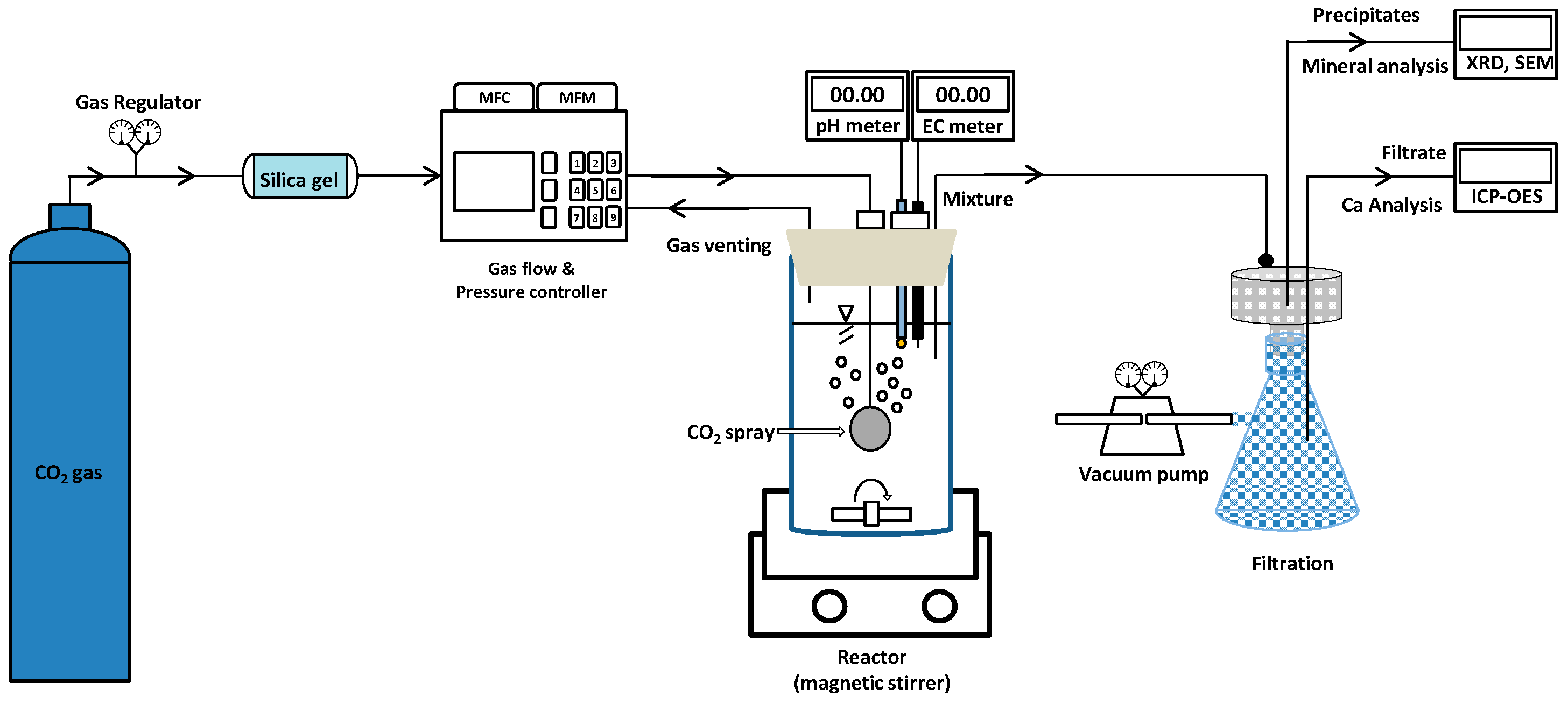
In this study, a carbon mineralization process was designed to neutralize wastewater generated from concrete sludge, and a schematic experimental flow diagram is provided in Figure 3. A batch type acrylic-material based experimental reactor was manufactured with a volume of 3.0 L (Φ: 140 mm, H: 200 mm) and a system created for measuring the solution pH and EC during the carbon mineralization process. In addition, the reactor was sealed in order to measure the volume of venting gas that had not reacted in aqueous solution to the injected gas volume and to prevent the gas leaking from the reactor. The exact volume of CO2 gas flow was controlled by a mass flow controller (MFC-CO2) and a mass flow management system (MFM-CO2). The total volume of gas venting was continuously analyzed using a gas flow and pressure controller (GMC1200, ATOVAC, Yongin-si, Korea).
2.2.2. Carbon Mineralization Experiment
The experimental conditions for all carbon mineralization experiments were as follows: 2.5 L of wastewater were reacted using a magnetic stirrer until the pH dropped to 8.5 at room temperature. The 99.9% CO2 gas flow rates (Jungang Gas Co., Ltd., Daejeon, Korea) were varied from 8–200 cc CO2/min/L (0.014–0.360 g CO2/min/L). Solution pH and EC, as well as the accumulated volume of gas venting to the injected volume of gas were measured during the experiments. After the experiments, the solution containing precipitates was immediately passed through a 0.45-µm paper with a vacuum filter press (0.6 MPa). The weight of the residual precipitates was measured after oven-drying at 105 °C for 4 h. The mineralogy and morphology of the precipitates were analyzed by XRD and scanning electron microscopy with energy dispersive spectroscopy (SEM-EDS, 6380LA, JEOL Ltd., Akishima-shi, Japan), respectively. All experiments were carried out in duplicate for quality assurance.
2.3. Neutralized Water Recycling
In this study, the removal efficiency of the neutralized waste water by carbon mineralization was evaluated in wastewater neutralized by carbon mineralization and subsequently reused in the wet-based crushing of the waste-concrete recycling process. The laboratory-scale experiments using a batch-type stirring vessel were carried out as follows: 15 g of raw-concrete powder (<75 µm; crushed using a jaw-crusher) were added to 150 mL of raw concrete sludge solution and neutralized water by the carbon mineralization processes (8, 40 and 200 cc CO2/min/L). The result was compared with that of as-received sludge solution. Tap water was also used as a control test. The mixture was mixed using a magnetic stirrer at 300 rpm for 2, 5, 10, 30, 60, 120 and 180 min at ambient temperature under atmospheric conditions. At the specified time, 10 mL of mixture were sampled and then passed through a syringe filter (0.45 µm). Solution pH and Ca concentration were measured from the filtrate, as per Section 2.1.
3. Results and Discussion
3.1. Physicochemical Characteristics of the Sample
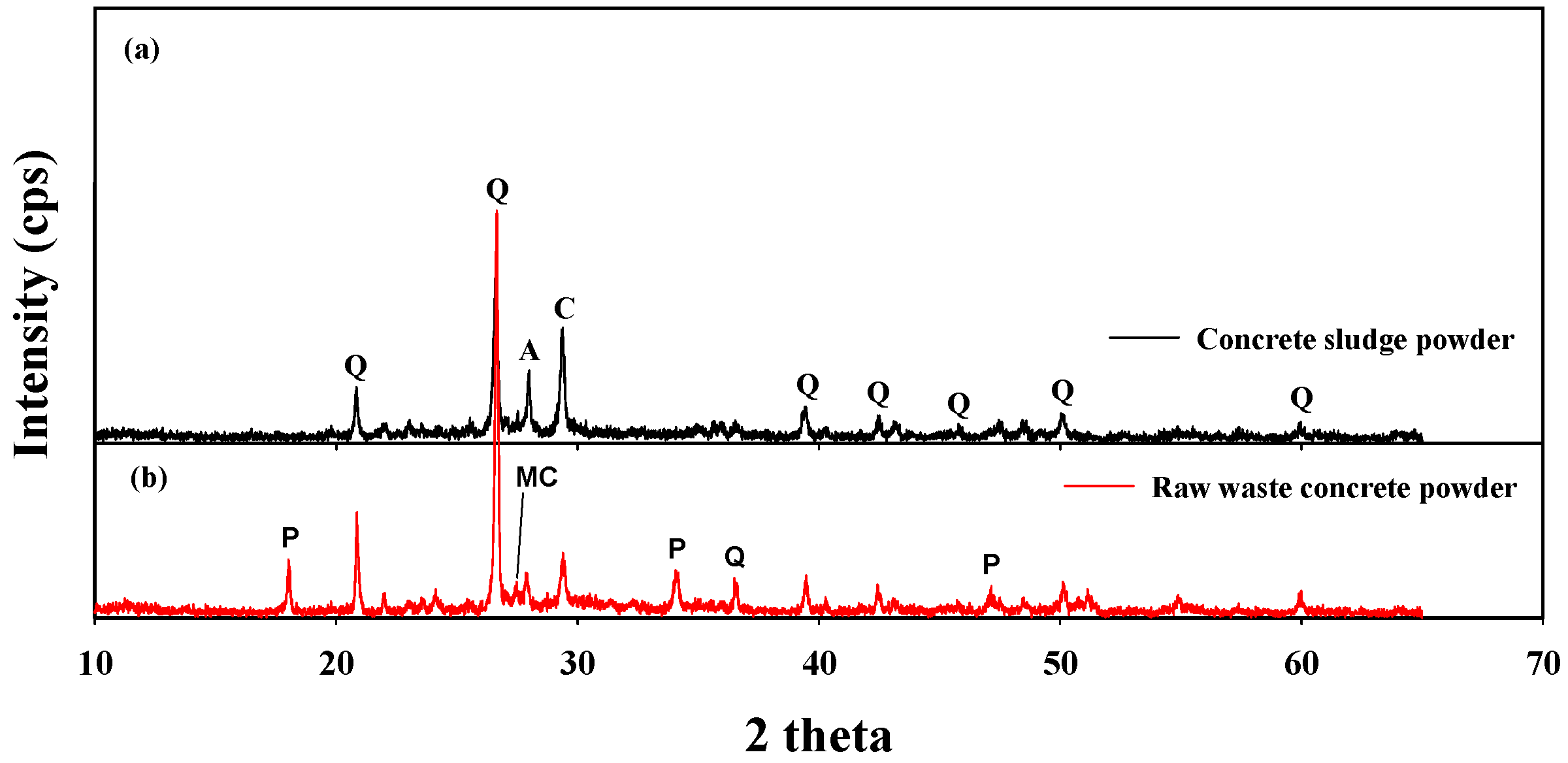
The physicochemical characteristics of the sludge sample are summarized in Table 1. The sludge pH was strongly alkaline (approximately 12.2) due to the hydroxide ions generated from dissolution of Ca(OH)2 contained in the cement (Equation (3)) [24]. The dissolved Ca ions in the concrete sludge were also sourced from Ca(OH)2 in the cement. Here, the pH and Ca concentration in solution were determined by the solubility constant of Ca(OH)2 (Ksp: 5.5 × 10⁻⁶) [17,25]. The sludge in this study was at pH 12.2 and contained approximately 330 mg/L of Ca. The high concentration of dissolved Ca2+, Na+, K+ and OH− in the sludge solution increased the EC to approximately 8.9 dS/m [26,27]. Quartz (SiO2), calcite (CaCO3) and the feldspar mineral albite (NaAlSi3O8) were identified by XRD in dried sludge particles (Figure 4a) [3]. Portlandite (Ca(OH)2), present in the original concrete (Figure 4b), was not observed in the concrete sludge XRD spectrum, possibly due to dissolution during the wet-based crushing/screening process. In addition, quartz and feldspar, including albite and microcline (KAlSi3O8), were derived from the mortar, the concrete production process or both [28,29], and lime had carbonated with the atmospheric CO2 [30]. Less calcium oxide was present in the concrete sludge compared with the concrete powder due to the dissolution of C3S, C2S, C3A, C4AF and Ca(OH)2 (Figure 4b and Table 2).
3.2. Carbon Mineralization
3.2.1. Changes in Solution pH and EC
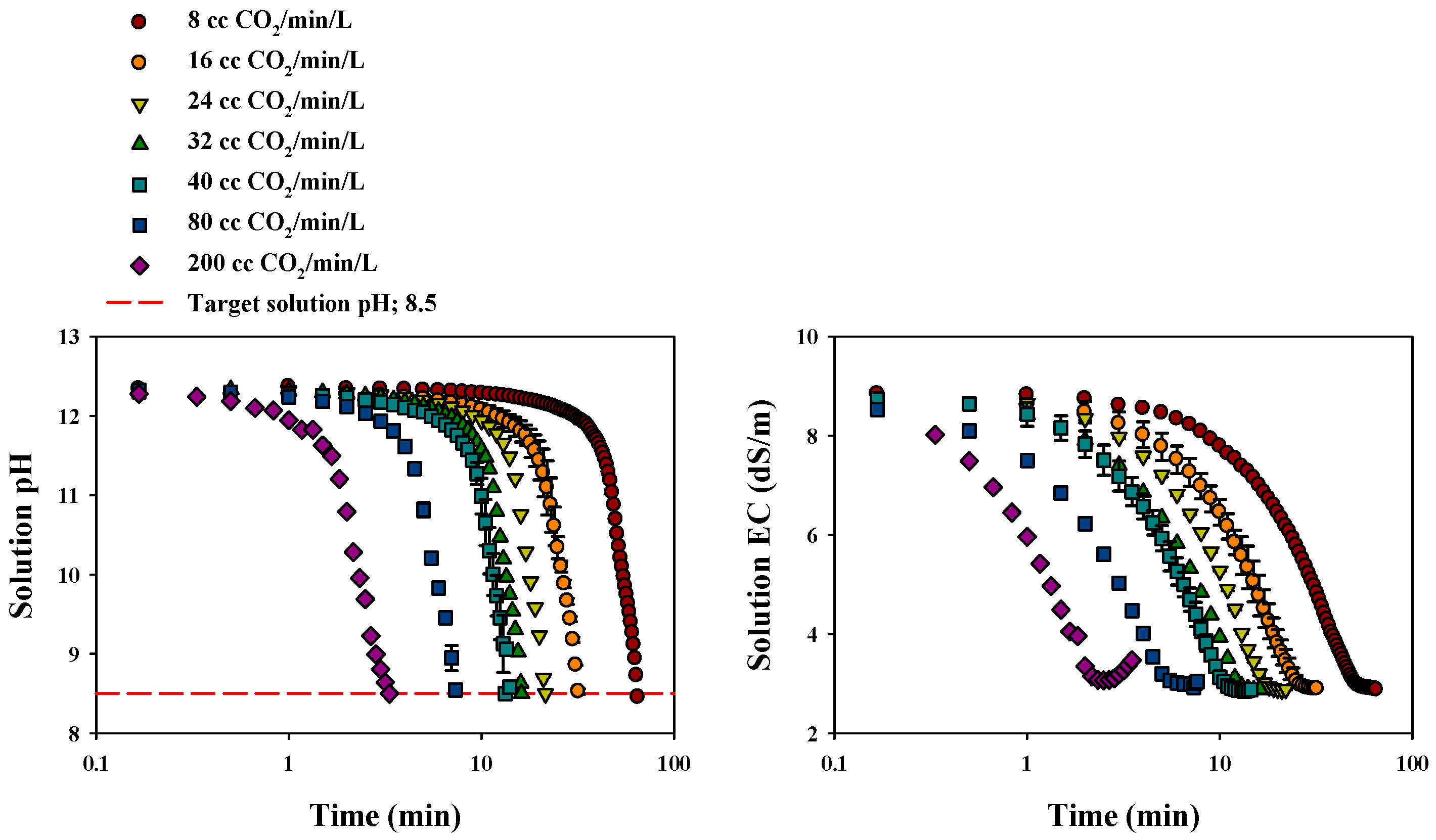
Figure 5 tracks the changes in solution pH and EC with gas flow rate during the carbon mineralization process. Protons generated by the carbonation reaction (Equations (1) and (2)) decreased the solution pH while consuming OH− ions [31]. The total reaction time required to neutralize alkaline solution pH was strongly dependent on the amount of CO2 gas injected [15]. These trends can be explained by the difference in the amount of protons generated from bicarbonate and carbonate reactions, following the dissolution of CO2 gas in aqueous solution. Azdarpour et al. [32] also reported that an increase in CO2 gas pressure (i.e., an increase in CO2 gas injection) enhanced the carbonation efficiency. In this current study, the protons that led to the decrease in solution pH were generated by the formation of CO32−, not HCO3−, above a solution pH of 8.5 [33]. The generation of CO32− cannot be accelerated under a solution pH of approximately 8.0 due to the equilibria of the carbonate system (i.e., acid dissociation constant: pKa). This phenomenon can be explained by the changes in solution EC during the carbon mineralization process and used to indirectly understand the changes in conductive ions in solution. Interestingly, solution EC rapidly decreased with the consumption of Ca ions due to the precipitation of CaCO3. Finally, solution EC was maintained at approximately 2.90 dS/m in all experiments due to the remaining conductive ions, including Na and K in solution, except where the gas flow rate was 200 cc CO2/min/L. Jo et al. [34] also observed that solution pH and EC simultaneously decreased with reaction time during the carbonation process in Ca-rich solutions. They reported that the decrease in solution EC was terminated due to the consumption of Ca ions through CaCO3 precipitation. In the 200 cc CO2/min/L experiment of the current study, however, the solution EC rapidly increased from 3.07 dS/m (the lowest EC value) to 3.47 dS/m at the end of the reaction. Han et al. [35] reported that CaCO3 produced by CO2 injection in the carbon mineralization process was converted to a soluble form of Ca(HNO3)2 at solution pH below 8.3, hence the slight increase in solution EC. This phenomenon might be interpreted as a stabilization of the final solution pH around 8.0, due to continuous proton production by a significant amount of un-solvated CO2 gas, even though the gas injection was stopped at solution pH 8.5. Chang et al. [36] reported that a higher CO2 flow rate decreased carbonation conversion due to poor CO2 mass transfer between gas and liquid phases; hence, the increase in Ca ions in solution with the dissolution of CaCO3 at a pH of approximately 8.0 [37]. Consequently, under high gas flow conditions, gas injection control is crucial for targeting the final solution pH to avoid re-dissolution of CaCO3.
3.2.2. CO2 Sequestration
The overall results of carbon mineralization experiments, with changes in the CO2 gas flow rate, are presented in Table 3. The consumption of the CO2 gas was calculated as in the following equation:
where Vin-accumulated and Vout-accumulated refer to the total volume of accumulated CO2 gas, injection and venting, respectively. The amounts of total CO2 injection and venting were calculated based on conditions at atmospheric pressure and a temperature of 20 °C.
More than 85% of the CO2 gas injected into the solution was consumed in neutralizing processes. Despite the reduction in the total reaction time required for neutralizing the alkaline solution pH, the increase in CO2 gas flow accelerated gas venting to the atmosphere instead of solvation within the aqueous solution. The continuous injection of CO2 gas resulted in a gradual increase in the CO2 gas venting due to saturation of carbonate ions with the decrease in Ca concentration in solution (Figure 6). Jo et al. [38] reported that the increase in carbonation time (i.e., with a lower CO2 gas flow injection rate) enhanced CO2 sequestration by slowing the decrease in solution pH. Furthermore, the increase of CO2 gas flow accelerated the gas venting with higher residual Ca concentrations in solution; thus, the amount of precipitated CaCO3 was reduced. This indicates that excessive CO2 gas flow (200 cc CO2/min/L) favors the precipitation of vaterite, due to the lack of reaction time [14,15]. Hence, Ca was re-extracted into solution from the vaterite with the decrease in solution pH [34]. This appears to agree with the rapid increase in solution EC from 3.1 dS/m–3.5 dS/m and the increase in Ca ions in solution.
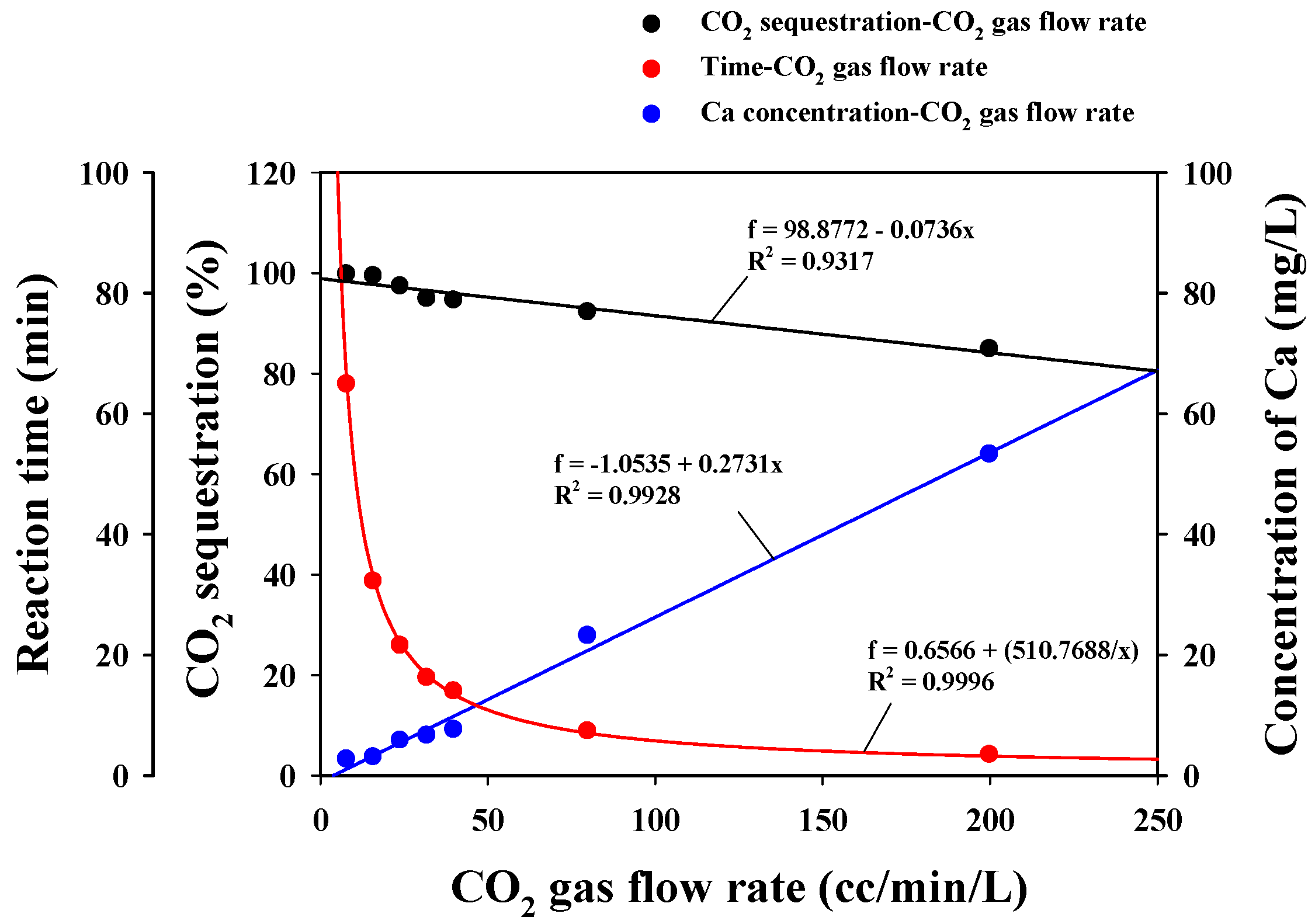
An efficient carbonation process requires optimal neutralizing conditions to balance CO2 sequestration, reaction time and dissolved Ca concentration remaining in solution. The relationships between these parameters are graphed in Figure 7. The fitting results reveal a good correlation between CO2 sequestration (R2 = 0.9996), reaction time (R2 = 0.9317), Ca concentration remaining in solution (R2 = 0.9928) and CO2 gas flow rates. According to equations calculated from each correlation result, the CO2 sequestration had to be 97.7% per total CO2 injection to achieve both pH neutralization and over 99% removal of Ca from the solution. The required reaction time for this CO2 sequestration was calculated at 32.4 min.
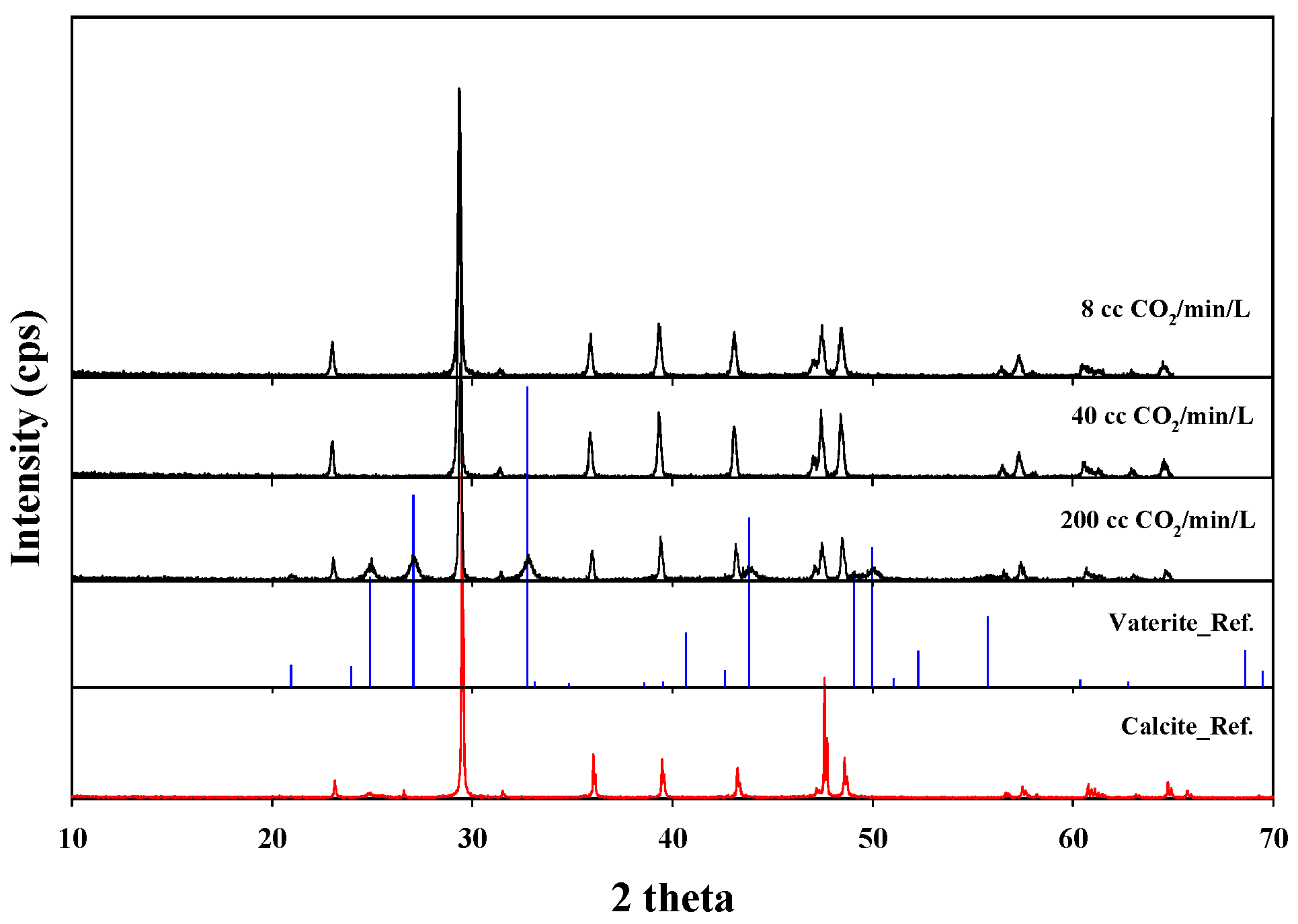
The amount of concrete sludge generated from the field treatment plant was approximately 3600 m3/day. The amount of CO2 gas sequestered by pH neutralization in the field plant was calculated for each gas flow rate selected in this study. Based on high purity CO2 gas (99.9%), the expected amount of CO2 gas sequestered was between approximately 21.3–26.7 and 0.1–4.0 tons CO2/day, at gas injection rates of 8–200 cc CO2/min/L, respectively. In comparison, based on the low CO2 content (15 vol %) of the flue gas discharged from coal-fired power plants, the amount of flue gas sequestrated and vented would be calculated between approximately 142.3–177.7 and 0.5–27.0 tons flue gas/day, respectively. In addition to the CO2 sequestration benefits of the carbon mineralization process, approximately 99.2% purity CaCO3 material could be produced. Applying the carbon mineralization process to the field-scale treatment plant (3600 m3/day), it was calculated to produce between approximately 2.6 and 3.9 tons CaCO3/day. At a higher rate of CO2 gas injection, spherical vaterite formed within the shortened reaction time (Figure 8 and Figure 9). In contrast, a longer application of the carbon mineralization process, with a lower gas flow rate, resulted in the vaterite transforming to more stable calcite crystals by reacting with water in the aqueous phase under atmospheric pressure conditions [18,39].
The increase in CO2 gas flow rate may have a positive effect on operating time and power consumption for the field-scale neutralization of alkaline wastewater. However, the high gas flow rate could cause problems such as a reduction in the amount of precipitated-CaCO3 and an increase in gas venting. Thus, when neutralized-water with a high Ca content is re-used, it could lead to a reduction in the efficiency of the wet-based crushing method in the waste-concrete recycling process. This study focused on the feasibility of neutralizing and re-using wastewater generated from concrete sludge without using acids; a detailed field-scale investigation is required to understand the overall economy of the process.
3.3. Evaluation of Neutralized Waste Water
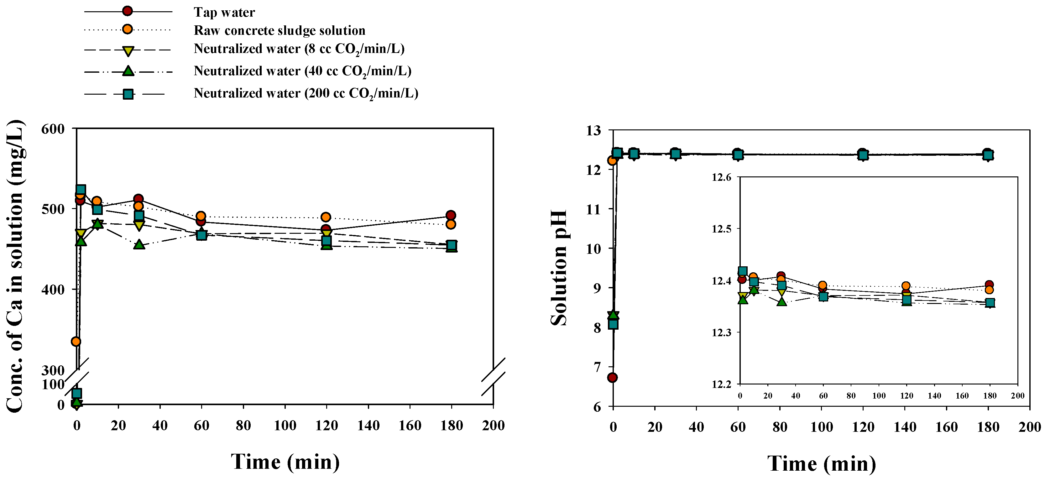
The removal efficiency of cement paste from aggregates was evaluated using raw concrete sludge solution before and after the suggested neutralization processes; it was also compared with the tap water control. The changes in solution pH and Ca concentration, with time, are presented in Figure 10. The waste water neutralized by carbon mineralization showed much lower Ca content as it was consumed in CaCO3 production. Solution pH and Ca concentration rapidly increased initially for tap water and neutralized water due to the dissolution of Ca(OH)2 in cement. However, they then slightly decreased with time, which means that a natural CaCO3 precipitate was produced through the reaction between atmospheric CO2 and Ca in solution. In the case of raw sludge solution, however, pH did not increase significantly, and Ca saturation was observed. In addition, the maximum solution pH and Ca concentrations were, for the most part, constant across the treatments due to Ca saturation of the solution. This indicates that with a higher gas flow rate the Ca remaining in water neutralized by carbon mineralization and raw sludge solution may have a negative effect on the removal Ca(OH)2 in cement from aggregates. Therefore, it should be possible to significantly manipulate the gas flow rate in the carbon mineralization process to enhance the removal of cement paste from the wet-based crushing process during the waste-concrete recycling process.
4. Conclusions
In this study, the carbon mineralization processes were investigated as a function of CO2 gas flow rates (8–200 cc CO2/min/L solution) to neutralize (target solution pH of 8.5) the Ca-rich alkaline concrete sludge solution generated from the recycling of waste concrete using a wet-based crushing process. Higher gas flow rates accelerated the drop in solution pH and EC; protons were generated by the carbonation reaction, while Ca ions precipitated out of solution as CaCO3. However, a high gas flow could lead to problems such as CO2 venting to the atmosphere and an increase in soluble Ca, as CaCO3 dissolved with a solution pH drop below the target pH of 8.5. In addition, water neutralized by a carbon mineralization process with a high gas flow rate, which remained Ca enriched, may not be efficient in the removal of cement paste (Ca(OH)2) from the wet-based crushing process of the waste-concrete recycling process. Therefore, the control of gas flow into the solution should be systematically manipulated in the carbon mineralization process to neutralize alkaline solutions containing large amounts of Ca. This process could make significant environmental and economic contributions by:
- (1)
- Providing an eco-friendly neutralization process for the treatment of alkaline wastewater.
- (2)
- Improving the cement paste removal process through the reuse of neutralized wastewater in the wet-based crushing process.
- (3)
- Sequestering CO2 in CaCO3.
- (4)
- Producing, as a by-product, a commercially viable pure source of CaCO3.
Acknowledgments
This research was supported by the Basic Research Project (17-3422) of the Korea Institute of Geoscience and Mineral Resources (KIGAM).
Author Contributions
Heeyoung Shin conceived and designed the experiments; Jongchan Yoo performed the experiments and analyzed the data; Heeyoung Shin and Sangwoo Ji contributed reagents/materials/analysis tools; Jongchan Yoo wrote the paper.
Conflicts of Interest
The authors declare no conflict of interest.
References
- Shin, H.Y.; Ji, S.; Woo, J.Y.; Ahn, G.O.; An, S.H. A feasibility study on the utilization of by-product sludge generated from waste concrete recycling process. J. Korean Inst. Resour. Recycl. 2016, 25, 29–36. [Google Scholar] [CrossRef]
- Ministry of Environment. Statistics Status of waste generation and treatment. In Construction Wastes; Sejong-si, Korea. Available online: http://stat.me.go.kr (accessed on 22 May 2017).
- Ghacham, A.B.; Pasquier, L.C.; Cecchi, E.; Blais, J.F.; Mercier, G. Valorization of waste concrete through CO2 mineral carbonation: Optimizing parameters and improving reactivity using concrete separation. J. Clean. Prod. 2017, 166, 869–878. [Google Scholar] [CrossRef]
- Behera, M.; Bhattacharyya, S.; Minocha, A.; Deoliya, R.; Maiti, S. Recycled aggregate from C&D waste & its use in concrete—A breakthrough towards sustainability in construction sector: A review. Constr. Build. Mater. 2014, 68, 501–516. [Google Scholar]
- Tsunashima, Y.; Iizuka, A.; Akimoto, J.; Hongo, T.; Yamasaki, A. Preparation of sorbents containing ettringite phase from concrete sludge and their performance in removing borate and fluoride ions from waste water. Chem. Eng. J. 2012, 200, 338–343. [Google Scholar] [CrossRef]
- Iizuka, A.; Sakai, Y.; Yamasaki, A.; Honma, M.; Hayakawa, Y.; Yanagisawa, Y. Bench-scale operation of a concrete sludge recycling plant. Ind. Eng. Chem. Res. 2012, 51, 6099–6104. [Google Scholar] [CrossRef]
- Lim, M.; Han, G.C.; Ahn, J.W.; You, K.S. Environmental remediation and conversion of carbon dioxide (CO2) into useful green products by accelerated carbonation technology. Int. J. Environ. Res. Public Health 2010, 7, 203–228. [Google Scholar] [CrossRef] [PubMed]
- Lee, M.G.; Kang, D.; Yoo, Y.; Jo, H.; Song, H.J.; Park, J. Continuous and simultaneous CO2 absorption, calcium extraction, and production of calcium carbonate using ammonium nitrate. Ind. Eng. Chem. Res. 2016, 55, 11795–11800. [Google Scholar] [CrossRef]
- Pan, S.Y.; Chang, E.; Chiang, P.C. CO2 capture by accelerated carbonation of alkaline wastes: A review on its principles and applications. Aerosol Air Qual. Res. 2012, 12, 770–791. [Google Scholar] [CrossRef]
- Ghacham, A.B.; Cecchi, E.; Pasquier, L.C.; Blais, J.F.; Mercier, G. CO2 sequestration using waste concrete and anorthosite tailings by direct mineral carbonation in gas–solid–liquid and gas–solid routes. J. Environ. Manag. 2015, 163, 70–77. [Google Scholar] [CrossRef] [PubMed]
- Gunning, P.J.; Hills, C.D.; Carey, P.J. Accelerated carbonation treatment of industrial wastes. Waste Manag. 2010, 30, 1081–1090. [Google Scholar] [CrossRef] [PubMed]
- Chen, Q.; Luo, Z.; Hills, C.; Xue, G.; Tyrer, M. Precipitation of heavy metals from wastewater using simulated flue gas: Sequent additions of fly ash, lime and carbon dioxide. Water Res. 2009, 43, 2605–2614. [Google Scholar] [CrossRef] [PubMed]
- Bertos, M.F.; Simons, S.; Hills, C.; Carey, P. A review of accelerated carbonation technology in the treatment of cement-based materials and sequestration of CO2. J. Hazard. Mater. 2004, 112, 193–205. [Google Scholar]
- Montes-Hernandez, G.; Renard, F.; Geoffroy, N.; Charlet, L.; Pironon, J. Calcite precipitation from CO2–H2 O–Ca (OH)2 slurry under high pressure of CO2. J. Cryst. Growth 2007, 308, 228–236. [Google Scholar] [CrossRef]
- Han, Y.S.; Hadiko, G.; Fuji, M.; Takahashi, M. Effect of flow rate and CO2 content on the phase and morphology of CaCO3 prepared by bubbling method. J. Cryst. Growth 2005, 276, 541–548. [Google Scholar] [CrossRef]
- Iizuka, A.; Sasaki, T.; Honma, M.; Yoshida, H.; Hayakawa, Y.; Yanagisawa, Y.; Yamasaki, A. Pilot-Scale Operation of a Concrete Sludge Recycling Plant and Simultaneous Production of Calcium Carbonate. Chem. Eng. Commun. 2017, 204, 79–85. [Google Scholar] [CrossRef]
- Kashef-Haghighi, S.; Shao, Y.; Ghoshal, S. Mathematical modeling of CO2 uptake by concrete during accelerated carbonation curing. Cem. Concr. Res. 2015, 67, 1–10. [Google Scholar] [CrossRef]
- Lee, M.G.; Kang, D.; Jo, H.; Park, J. Carbon dioxide utilization with carbonation using industrial waste-desulfurization gypsum and waste concrete. J. Mater. Cycles Waste 2016, 18, 407–412. [Google Scholar] [CrossRef]
- Palaniandy, S.; Kadir, N.A.; Jaafar, M. Value adding limestone to filler grade through an ultra-fine grinding process in jet mill for use in plastic industries. Miner. Eng. 2009, 22, 695–703. [Google Scholar] [CrossRef]
- Said, A.; Laukkanen, T.; Järvinen, M. Pilot-scale experimental work on carbon dioxide sequestration using steelmaking slag. Appl. Energy 2016, 177, 602–611. [Google Scholar] [CrossRef]
- Chuajiw, W.; Takatori, K.; Igarashi, T.; Hara, H.; Fukushima, Y. The influence of aliphatic amines, diamines, and amino acids on the polymorph of calcium carbonate precipitated by the introduction of carbon dioxide gas into calcium hydroxide aqueous suspensions. J. Cryst. Growth 2014, 386, 119–127. [Google Scholar] [CrossRef]
- Singh, M.; Kumar, S.V.; Waghmare, S.A.; Sabale, P. Aragonite–vaterite–calcite: Polymorphs of CaCO3 in 7th century CE lime plasters of Alampur group of temples, India. Constr. Build. Mater. 2016, 112, 386–397. [Google Scholar] [CrossRef]
- Dri, M.; Sanna, A.; Maroto-Valer, M.M. Mineral carbonation from metal wastes: Effect of solid to liquid ratio on the efficiency and characterization of carbonated products. Appl. Energy 2014, 113, 515–523. [Google Scholar] [CrossRef] [Green Version]
- Phung, Q.T.; Maes, N.; Jacques, D.; De Schutter, G.; Ye, G.; Perko, J. Modelling the carbonation of cement pastes under a CO2 pressure gradient considering both diffusive and convective transport. Constr. Build. Mater. 2016, 114, 333–351. [Google Scholar] [CrossRef]
- Dean, J.A. Lange’s Hand Book of Chemistry, 13th ed.; McGrawHill, Inc.: New York, NY, USA, 1985. [Google Scholar]
- Cordeiro, G.C.; Sales, C.P. Pozzolanic activity of elephant grass ash and its influence on the mechanical properties of concrete. Cem. Concr. Compos. 2015, 55, 331–336. [Google Scholar] [CrossRef]
- Morsy, M.S. Effect of temperature on electrical conductivity of blended cement pastes. Cem. Concr. Res. 1999, 29, 603–606. [Google Scholar] [CrossRef]
- Maravelaki-Kalaitzaki, P.; Galanos, A.; Doganis, I.; Kallithrakas-Kontos, N. Physico-chemical characterization of mortars as a tool in studying specific hydraulic components: Application to the study of ancient Naxos aqueduct. Appl. Phys. A Mater. 2011, 104, 335–348. [Google Scholar] [CrossRef]
- Gulotta, D.; Goidanich, S.; Tedeschi, C.; Nijland, T.G.; Toniolo, L. Commercial NHL-containing mortars for the preservation of historical architecture. Part 1: Compositional and mechanical characterisation. Constr. Build. Mater. 2013, 38, 31–42. [Google Scholar] [CrossRef]
- Mackie, A.L.; Walsh, M.E. Bench-scale study of active mine water treatment using cement kiln dust (CKD) as a neutralization agent. Water Res. 2012, 46, 327–334. [Google Scholar] [CrossRef] [PubMed]
- Han, Y.S.; Ji, S.; Lee, P.K.; Oh, C. Bauxite residue neutralization with simultaneous mineral carbonation using atmospheric CO2. J. Hazard. Mater. 2017, 326, 87–93. [Google Scholar] [CrossRef] [PubMed]
- Azdarpour, A.; Asadullah, M.; Mohammadian, E.; Junin, R.; Hamidi, H.; Manan, M.; Daud, A.R.M. Mineral carbonation of red gypsum via pH-swing process: Effect of CO2 pressure on the efficiency and products characteristics. Chem. Eng. J. 2015, 264, 425–436. [Google Scholar] [CrossRef]
- Sahu, R.C.; Patel, R.K.; Ray, B.C. Neutralization of red mud using CO2 sequestration cycle. J. Hazard. Mater. 2010, 179, 28–34. [Google Scholar] [CrossRef] [PubMed]
- Jo, H.Y.; Kim, J.H.; Lee, Y.J.; Lee, M.; Choh, S.J. Evaluation of factors affecting mineral carbonation of CO2 using coal fly ash in aqueous solutions under ambient conditions. Chem. Eng. J. 2012, 183, 77–87. [Google Scholar] [CrossRef]
- Han, S.J.; Im, H.J.; Wee, J.H. Leaching and indirect mineral carbonation performance of coal fly ash-water solution system. Appl. Energy 2015, 142, 274–282. [Google Scholar] [CrossRef]
- Chang, E.E.; Chiu, A.C.; Pan, S.Y.; Chen, Y.H.; Tan, C.S.; Chiang, P.C. Carbonation of basic oxygen furnace slag with metalworking wastewater in a slurry reactor. Int. J. Greenh. Gas Control 2013, 12, 382–389. [Google Scholar] [CrossRef]
- Jo, H.; Young Jo, H.; Jang, Y.N. Effect of extraction solutions on carbonation of cementitious materials in aqueous solutions. Environ. Technol. 2012, 33, 1391–1401. [Google Scholar] [CrossRef] [PubMed]
- Jo, H.Y.; Ahn, J.H.; Jo, H. Evaluation of the CO2 sequestration capacity for coal fly ash using a flow-through column reactor under ambient conditions. J. Hazard. Mater. 2012, 241, 127–136. [Google Scholar] [CrossRef] [PubMed]
- Kang, D.; Jo, H.; Lee, M.G.; Park, J. Carbon dioxide utilization using a pretreated brine solution at normal temperature and pressure. Chem. Eng. J. 2016, 284, 1270–1278. [Google Scholar] [CrossRef]
Figure 1.
Photographs of a field waste concrete recycling process.
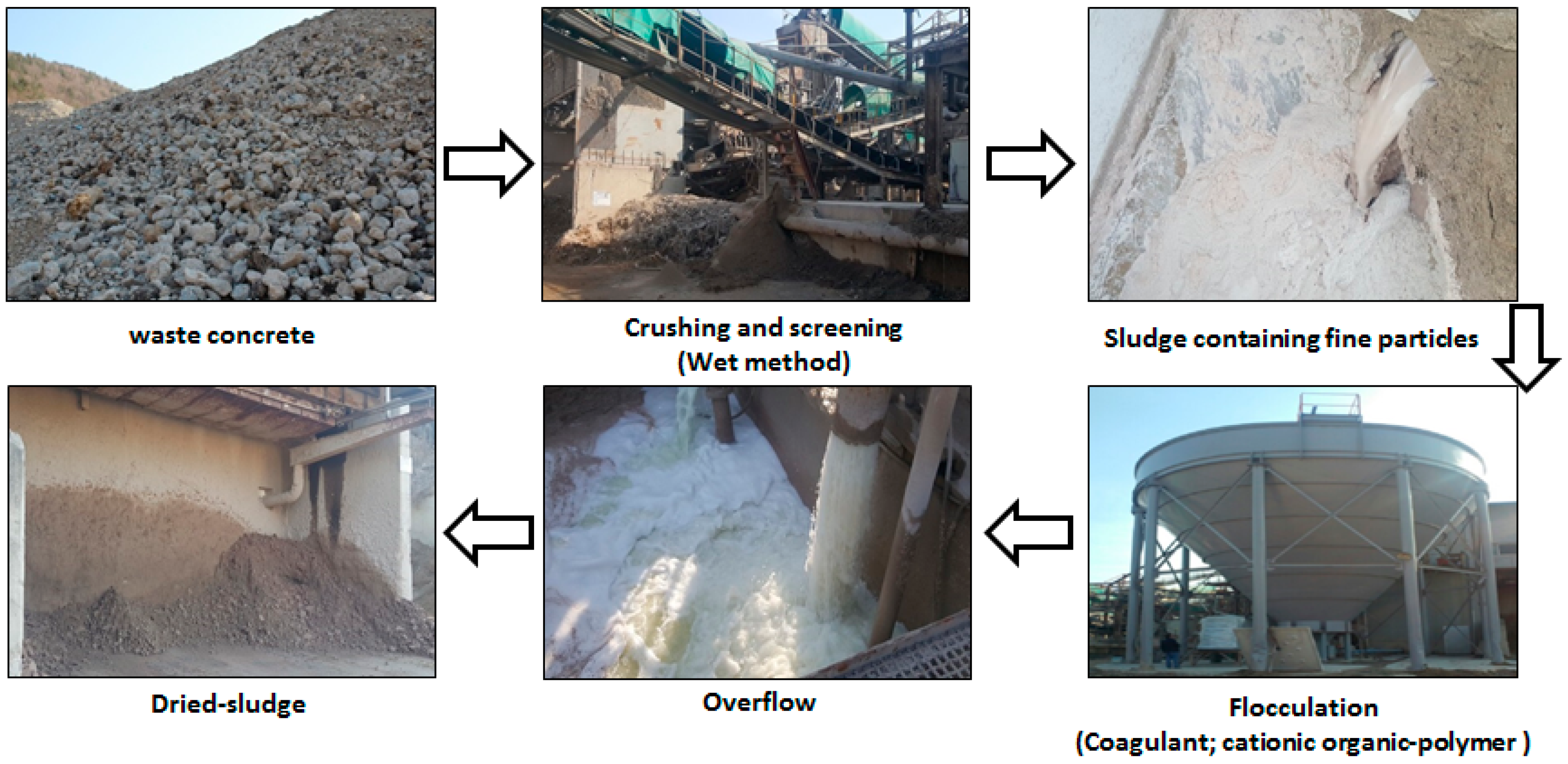
Figure 2.
A schematic flow diagram of the neutralization of Ca-rich alkaline wastewater from a waste concrete recycling process by carbon mineralization.
Figure 2.
A schematic flow diagram of the neutralization of Ca-rich alkaline wastewater from a waste concrete recycling process by carbon mineralization.
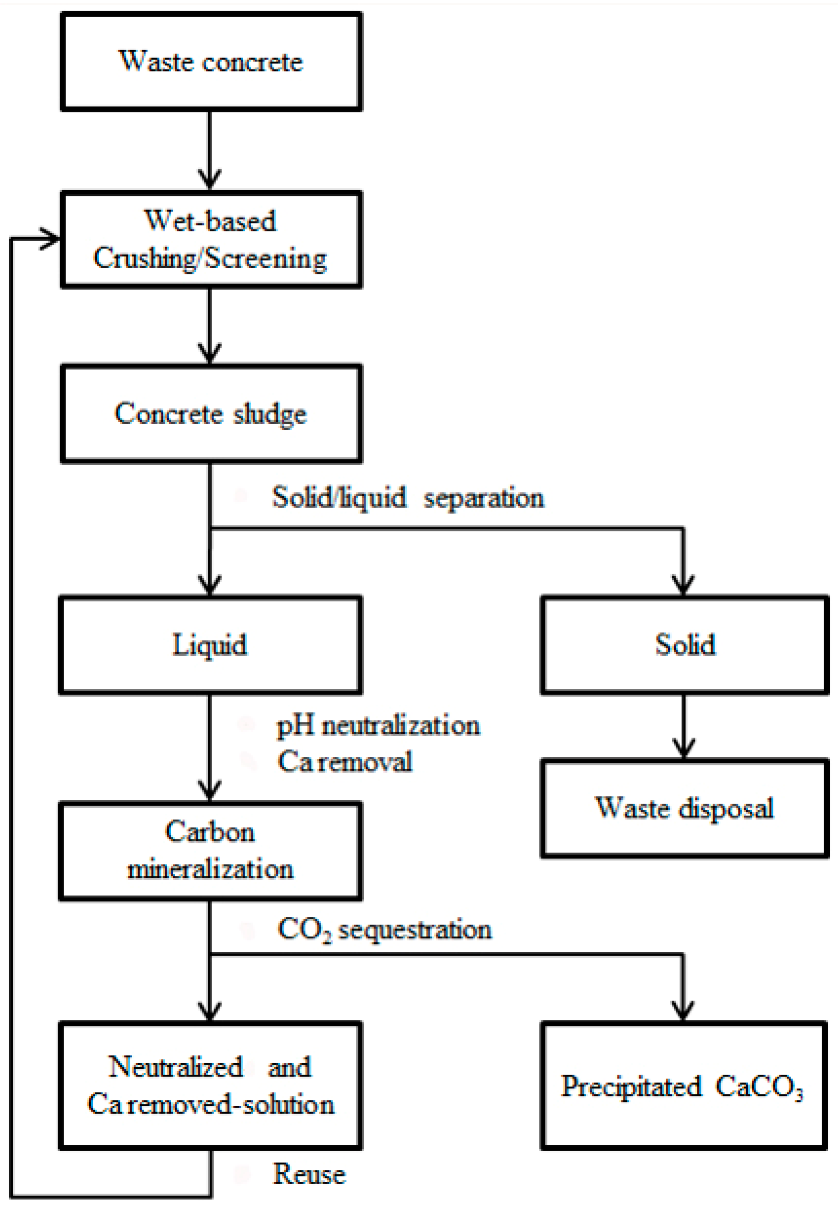
Figure 3.
A schematic experimental flow diagram of the carbon mineralization process (MFC: mass flow controller; MFM: mass flow management system; EC: electrical-conductivity).
Figure 3.
A schematic experimental flow diagram of the carbon mineralization process (MFC: mass flow controller; MFM: mass flow management system; EC: electrical-conductivity).

Figure 4.
The X-ray diffractogram for concrete sludge powder (a) and raw waste concrete powder (b); peaks are identified for quartz (Q: SiO2), calcite (C: CaCO3), albite (A: NaAlSi3O8), microcline (MC: KAlSi3O8) and portlandite (P: Ca(OH)2).
Figure 4.
The X-ray diffractogram for concrete sludge powder (a) and raw waste concrete powder (b); peaks are identified for quartz (Q: SiO2), calcite (C: CaCO3), albite (A: NaAlSi3O8), microcline (MC: KAlSi3O8) and portlandite (P: Ca(OH)2).

Figure 5.
Changes in solution pH and EC during the carbon mineralization processes.

Figure 6.
Accumulated CO2 venting to the atmosphere during carbon mineralization processes.
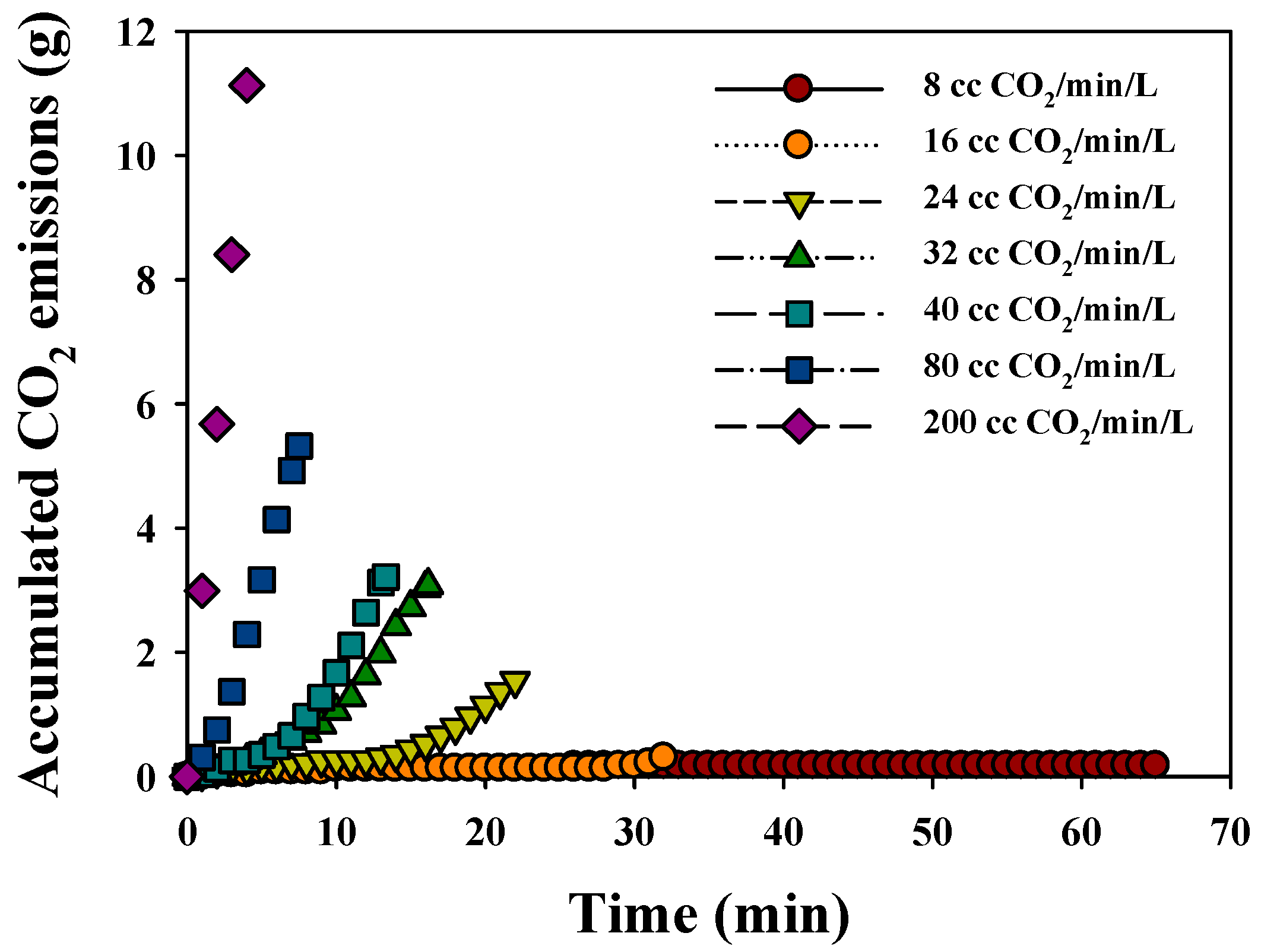
Figure 7.
Correlation between CO2 sequestration, reaction time and residual Ca concentration and CO2 gas flow rate during the carbon mineralization processes.
Figure 7.
Correlation between CO2 sequestration, reaction time and residual Ca concentration and CO2 gas flow rate during the carbon mineralization processes.

Figure 8.
The XRD spectra of particles precipitated during the carbon mineralization processes at 8, 40 and 200 cc CO2/min/L.
Figure 8.
The XRD spectra of particles precipitated during the carbon mineralization processes at 8, 40 and 200 cc CO2/min/L.

Figure 9.
(a–c) The SEM images of CaCO3 particles precipitated through the carbon mineralization processes (8, 40 and 200 cc CO2/min/L).
Figure 9.
(a–c) The SEM images of CaCO3 particles precipitated through the carbon mineralization processes (8, 40 and 200 cc CO2/min/L).
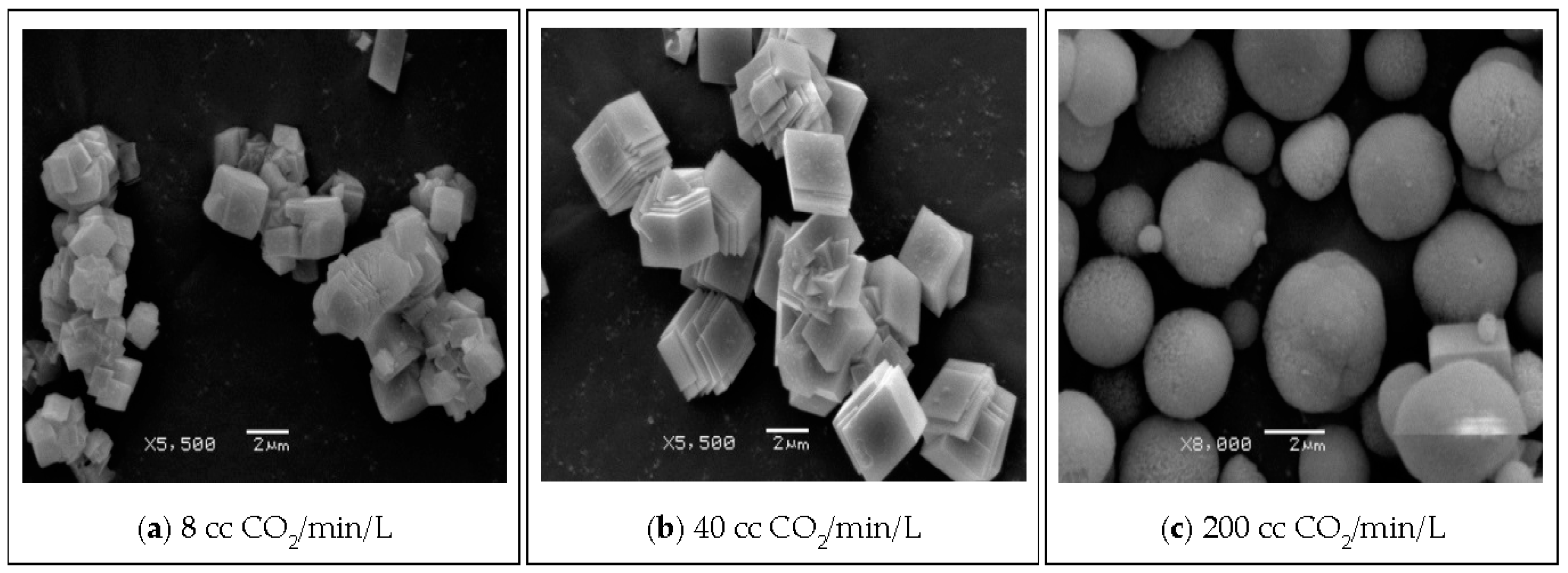
Figure 10.
Changes in Ca concentration and solution pH from raw concrete powder dissolution using tap water, raw concrete sludge solution and neutralized water by carbon mineralization (8, 40 and 200 cc CO2/min/L).
Figure 10.
Changes in Ca concentration and solution pH from raw concrete powder dissolution using tap water, raw concrete sludge solution and neutralized water by carbon mineralization (8, 40 and 200 cc CO2/min/L).


Table 1.
Physicochemical properties of concrete sludge used in this study.
| Parameter | Value |
|---|---|
| pH | 12.2 |
| EC (dS/m) | 8.9 |
| ORP a (mV) | −108.0 |
| Moisture content (%) | 92.5 |
| Particle size distribution (wt %) (KS F 2309 b) | |
| >70 mesh (>0.212 mm) | 1.3 |
| 70–100 mesh (0.212–0.150 mm) | 0.4 |
| 100–200 mesh (0.150–0.075 mm) | 7.9 |
| 200–325 mesh (0.075–0.043 mm) | 9.5 |
| 325–400 mesh (0.043–0.038 mm) | 7.7 |
| <400 mesh (<0.038 mm) | 73.1 |
| Elements in aqueous solution (mg/L) | |
| Ca | 333.9 ± 2.0 |
| K | 257.1 ± 1.4 |
| Na | 317.5 ± 0.0 |
a ORP: Oxidation Reduction Potential; b KS F 2309: Korean Standard Testing Method.
Table 2.
Chemical composition of dried-solid particles in concrete sludge (XRF analysis).
| Oxide | Composition (wt %) | |
|---|---|---|
| Dried Concrete Sludge | Raw Waste Concrete | |
| SiO2 | 45.9 | 38.5 |
| CaO | 20.2 | 30.2 |
| Al2O3 | 9.4 | 6.9 |
| Fe2O3 | 3.0 | 4.1 |
| MgO | 1.5 | 1.8 |
| K2O | 2.3 | 1.9 |
| LOI a | 15.4 | 14.5 |
| Others b | 1.8 | 1.6 |
a Loss of ignition; b Na2O, TiO2, MnO and P2O5 included.
Table 3.
Overall results of carbon mineralization processes with changes in CO2 gas flow rates (2.5 L of solution).
Table 3.
Overall results of carbon mineralization processes with changes in CO2 gas flow rates (2.5 L of solution).
| CO2 Gas Flow Rate (cc/min/L) | Time (min) | Final EC (dS/m) | Total CO2 Injection (g) | Total CO2 Venting (mg) | CO2 Sequestration (1 − (Vout/Vin)) | Conc. of Ca (mg/L) | Precipitated CaCO3 (g) |
|---|---|---|---|---|---|---|---|
| 8 | 65.0 | 2.9 | 2.38 | 7.33 | 1.00 | 2.64 | 2.69 |
| 16 | 32.0 | 2.9 | 2.09 | 13.74 | 0.99 | 3.00 | 2.60 |
| 24 | 22.0 | 2.9 | 2.23 | 59.52 | 0.97 | 5.76 | 2.64 |
| 32 | 16.2 | 2.9 | 2.33 | 120.87 | 0.95 | 6.58 | 2.58 |
| 40 | 13.3 | 2.9 | 2.35 | 129.11 | 0.95 | 7.55 | 2.66 |
| 80 | 7.5 | 3.0 | 2.72 | 212.44 | 0.92 | 23.13 | 2.50 |
| 200 | 3.4 | 3.5 | 3.05 | 463.33 | 0.85 | 53.21 | 1.78 |
© 2017 by the authors. Licensee MDPI, Basel, Switzerland. This article is an open access article distributed under the terms and conditions of the Creative Commons Attribution (CC BY) license (http://creativecommons.org/licenses/by/4.0/).
Share and Cite
MDPI and ACS Style
Yoo, J.; Shin, H.; Ji, S. An Eco-Friendly Neutralization Process by Carbon Mineralization for Ca-Rich Alkaline Wastewater Generated from Concrete Sludge. Metals 2017, 7, 371. https://doi.org/10.3390/met7090371
AMA Style
Yoo J, Shin H, Ji S. An Eco-Friendly Neutralization Process by Carbon Mineralization for Ca-Rich Alkaline Wastewater Generated from Concrete Sludge. Metals. 2017; 7(9):371. https://doi.org/10.3390/met7090371
Chicago/Turabian StyleYoo, Jongchan, Heeyoung Shin, and Sangwoo Ji. 2017. "An Eco-Friendly Neutralization Process by Carbon Mineralization for Ca-Rich Alkaline Wastewater Generated from Concrete Sludge" Metals 7, no. 9: 371. https://doi.org/10.3390/met7090371
Note that from the first issue of 2016, this journal uses article numbers instead of page numbers. See further details here.