Physical-Mechanism Exploration of the Low-Cycle Unified Creep-Fatigue Formulation


Department of Mechanical Engineering, University of Canterbury, Christchurch 8140, New Zealand
*
Author to whom correspondence should be addressed.
Metals 2017, 7(9), 379; https://doi.org/10.3390/met7090379
Submission received: 18 August 2017
/
Revised: 15 September 2017
/
Accepted: 15 September 2017
/
Published: 18 September 2017
(This article belongs to the Special Issue Fatigue Damage)
Abstract
:Background—Creep-fatigue behavior is identified as the incorporated effects of fatigue and creep. One class of constitutive-based models attempts to evaluate creep and fatigue separately, but the interaction of fatigue and creep is neglected. Other models treat the damage as a single component, but the complex numerical structures that result are inconvenient for engineering application. The models derived through a curve-fitting method avoid these problems. However, the method of curving fitting cannot translate the numerical formulation to underlying physical mechanisms. Need—Therefore, there is a need to develop a new creep-fatigue formulation for metal that accommodates all relevant variables and where the relationships between them are consistent with physical mechanisms of fatigue and creep. Method—In the present work, the main dependencies and relationships for the unified creep-fatigue equation were presented through exploring what the literature says about the mechanisms. Outcomes—This shows that temperature, cyclic time and grain size have significant influences on creep-fatigue behavior, and the relationships between them (such as linear relation, logarithmical relation and power-law relation) are consistent with phenomena of diffusion creep and crack growth. Significantly, the numerical form of “1 − x” is presented to show the consumption of creep effect on fatigue capacity, and the introduction of the reference condition gives the threshold of creep effect. Originality—By this means, the unified creep-fatigue equation is linked to physical phenomena, where the influence of different dependencies on creep fatigue was explored and relationships shown in this equation were investigated in a microstructural level. Particularly, a physical explanation of the grain-size exponent via consideration of crack-growth planes was proposed.
1. Introduction
Creep-fatigue damage is physically explained as the combined effects of fatigue and creep, due to reversed loading and elevated temperature respectively. Historically, creep-fatigue models have been developed through either a constitutive-based method, or an empirically-based method.
The constitutive-based method is typically conducted by exploring the underlying physical mechanisms of fatigue and creep, and by including parameters representing the properties of the material. Some constitutive models have been extended from the conventional idea of continuum damage, including the linear damage rule [1,2] and the crack growth law [3]. Examples of such models are those proposed by Takahashi [4,5] and Warwick [6] which are based on ductility and energy exhaustion with the total damage being divided into fatigue damage and creep damage, the model proposed by Sehitoglu [7] that divides the total damage into three sub-damages caused by fatigue, oxidation and creep, and the model proposed by Ainsworth [8] that partitions the crack as a whole into sub-effects caused by fatigue and creep.
The constitutive models based on continuum damage are successful in evaluating creep and fatigue separately, but do not address the interaction of fatigue and creep, hence weakening the applicability. The deeper issue is that the interactive effect between fatigue and creep is complex and the numerical formulism is unknown. Thus, it is difficult to further improve the continuum-damage-based models by introducing an interactive effect. Some constitutive models try to avoid the need to evaluate the interactive component, by treating the total damage or the fatigue ability as a single component. Examples are the model [9,10] extended from the Chaboche model [11], the model [12,13] that described the crack-tip behavior, and the model [14,15] that evaluated dissipated energy. Although these models present a comprehensive numerical representation of creep fatigue, they provide mathematically complex structures. Therefore, these models are not convenient to be used by engineers who need to obtain fatigue life through simpler physical parameters such as applied loading, temperature and cyclic time.
The empirical-based method is typically conducted by fitting mathematical formula to the empirical data, with the emphasis on high quality of fit. The empirical-based models might be more favorable since these models provide simpler/clearer numerical representations. By the empirical-based method the creep-fatigue behavior is numerically represented—this is achieved by incorporating the creep-related parameters into one of the conventional fatigue models, such as the Basquin equation [16] for the high-cycle regime, or the Coffin-Manson equation [17,18] for the low-cycle regime.
The low-cycle creep-fatigue behavior has received much attention, and resulted in different strain-based creep-fatigue models. The first model developed by the empirical-based method was attempted by Coffin [19], who proposed the frequency-modified Coffin-Manson equation. Then, this formulation was further modified by Solomon [20] and Shi et al. [21] through directly introducing a temperature dependency. Discarding the family of equations based on the frequency-modified Coffin-Manson equation has given additional numerical representations of creep fatigue, such as the equations proposed by Jing et al. [22], Engelmaier [23] and Wong and Mai [24].
However, these creep-fatigue models have significant limitations. The issue is that there are multiple variables to model: failure mode (creep, creep-fatigue and fatigue), multiple temperatures, different cyclic times (frequency), and different materials (type of material and grade thereof). The existing curve-fitting models cover one or both of variable temperature and cyclic time, but are specific to one material grade. This is because these models were derived from one specific situation. In addition, these existing models cannot cover the full range of conditions from pure fatigue to pure creep, since they were derived from the empirical data of creep fatigue. In this case, the existing models cannot natively be extended to other materials or failure modes. Furthermore, these existing models cannot provide an economical method for engineering design because numerous creep-fatigue experiments are required to achieve high quality of curve fitting.
These three disadvantages arise as an intrinsic limitation of the method of curve fitting, since statistical fitting accuracy does not necessarily translate to a robust description of the underlying physical mechanisms. Therefore, these models are only numerical representations of creep-fatigue behavior, and no underlying physical mechanisms of fatigue and creep are provided. The fitting method and related existing creep-fatigue models do not provide a route to achieve a unified formulation across multiple materials, integrated representation of failure modes, and engineering economy. However, these disadvantages are recently improved by the low-cycle unified creep-fatigue equation [25,26,27] (the description of this new model will be presented in Section 2). While this new model does not formalize the interactive effect between fatigue and creep, nonetheless the error of life prediction caused by this is within an acceptable range (we assume the ratio of predicted fatigue life to experimental result is between 0.75 and 1.25). This is because the coefficients in this new model are not solely derived from the empirical data of pure fatigue or/and pure creep, even though the relationships between different variables in this model are based on the mechanisms of fatigue and creep.
The purpose of the current paper is to link the low-cycle unified creep-fatigue equation to physical phenomena. To do this we considered each of the main dependencies (including temperature, cyclic time and grain size) and relationships for the unified creep-fatigue equation, and explored what the literature says about the mechanisms of fatigue and creep. Specifically, the creep and fatigue mechanisms based on the underlying physical mechanisms in terms of temperature, cyclic time and grain size were discussed, then the consistency between the physical mechanisms and the structure of the unified creep-fatigue equation was investigated.
2. Brief Description of the Unified Model
The low-cycle unified creep-fatigue equation (Equation (1)) [25,26,27] is presented as follow:
where is the plastic strain, is the fatigue ductility coefficient, is the fatigue ductility exponent, N is the creep-fatigue life, is the stress, T is the temperature, is the cyclic time, d is the grain size, is the reference temperature, is the reference cyclic time, is the reference grain size, and A and m are constants. The derivation of this unified creep-fatigue formulation is based on the concept of fatigue capacity, which numerically shows the process of gradual consumption of full fatigue capacity by creep effect. Particularly, the relationships between different variables in this unified formulation can be explained by physical meaning. This is a remarkable characteristic for this new formulation, which results in several significant advantages on the creep-fatigue description. Specifically, the unified creep-fatigue equation was well validated at multiple temperatures and cyclic times for multiple materials [25,26,27], such as 63Sn37Pb, 96.5Sn3.5Ag, stainless steel 316 and Inconel 718, thus the unified characteristic is presented. In addition, this unified formulation can be restored to the Coffin-Manson equation at pure-fatigue condition and can be reorganized to the Manson-Haferd parameter [28] at pure-creep condition, thus the integrated characteristic is included. Furthermore, the coefficients of this unified formulation can be extracted with minimum experimental effort, which provides an effective and efficient method for engineering design. In general, function and constant are extracted from creep-rupture tests, and the constants , , A and m are derived from creep-fatigue tests. A brief description of the validation on material GP91 casting steel is presented below, based on [25]. Briefly, the pure-creep condition () gives the formula of the constant (Equation (2)) through letting T = Tref, and suggests function (Equation (3)) through letting tc = tref.
Then, creep-fatigue data are applied to obtain the constants of A, m, and through minimizing the error (Equation (4)) between the predicted creep-fatigue life () and experimental results ():
The reference temperature for GP91 casting steel is chosen as 610 K, the reference cyclic time is defined as 1 s, and the reference grain size is selected as 25 μm. The creep-rupture data [29] gives the point of convergence (Tref, logta) which is evaluated as (610 K, 18.281), and thus,
And the relationship between stress and the Manson-Hafer parameter () is given as:
Then, substituting Equations (5) and (6) into Equation (3), function is expressed as:
where is a moderating factor which is introduced to compress the constant stress into an equivalent creep damage under the cyclic situation. The magnitude of is given as 0.6366 for the sinusoidal wave. The empirical data of creep fatigue (T = 673 K, tc = 5 s, d = 25 μm; T = 823 K, tc = 5 s, d = 25 μm; T = 873 K, tc = 2 s, d = 35 μm) obtained from Ref. [30] give the constants of , , A and m through minimizing the difference between predicted life and experimental life (numerically optimization) (Equation (4)). Specifically, = 0.9532, = 0.669, A = 0.5588 and m = −0.4053. In addition, the ratios of predicted fatigue life to experimental fatigue life are plotted in Figure 1. This figure shows that all data points fall in a reasonable range (within the upper bound (+25%) and the lower bound (−25%)). This implies that the unified formulation has high accuracy of fatigue-life prediction.
We also indicated that the unified formulation provides a more economical method of fatigue-life evaluation for engineering application. This was discussed and proved in [31], where the unified formulation was compared with Wong and Mai’s equation. Specifically, taking 63Sn37Pb solder as an example, both Wong and Mai’s equation and the unified formulation give high accuracy of fatigue-life prediction when all eight groups of creep-fatigue data are imposed. Then, three groups of creep-fatigue data were selected to extract the coefficients of these two formulations. When Wong and Mai’s equation with the coefficients obtained at this stage is extended to predict fatigue life at total eight creep-fatigue situations, the average error dramatically worsens. However, only a slight reduction of average error was presented by the unified formulation. This implies that the unified formulation requires less creep-fatigue experiments to extract the coefficients, and thus a more economical method is provided for engineering application.
Overall, the new model presents a good balance between accuracy and economy, which is very important for engineering applications. More information of the advantages presented by the unified formulation is shown in Ref. [31].
3. Influence of Relevant Variables on Creep-Fatigue Behavior
Creep-fatigue process presents the fatigue behavior under elevated temperature, where creep effect is active. At the microstructural level, fatigue and creep show different underlying principles. Generally, fatigue effect occurs via cracks through the grains, while creep effect involves the grain boundary cracking [32]. The accumulation of creep-fatigue damage implies that full fatigue capacity is gradually consumed by creep effect, which is macroscopically influenced by temperature and cyclic time, and is related to grain size in the microstructural level. These relevant variables are accommodated in the unified creep-fatigue equation. We discuss these three main dependencies since they are frequently investigated and presented in the existing creep-fatigue models. Practically, the creep-fatigue behavior is also influenced by other effects, such as mean stress/strain and applied loading. The effect of mean stress/strain is not included into the unified equation, which is a limitation of this new model and will be considered in future research. In addition, the effect of applied loading (stress and strain) on creep is indirectly incorporated into function , where this function is extracted through the relationship between applied loading and the Manson-Haferd parameter. It is generally accepted that the increased loading results in more vulnerable bonds between atoms due to change to inter-atomic spacing. This provides a favorable situation to initiate the atomic movements. In this case, creep damage is intensified with increased loading, and then fatigue capacity is reduced.
The influences of these three main variables (temperature, frequency/cyclic time and grain size) are shown below.
3.1. Temperature Dependency
Temperature has significant influence on creep, but presents negligible effect on pure fatigue [33] where creep is dormant. Normally, creep effect is activated when temperature is higher than 35% of the melting temperature [34], which may be attributed to the behavior of atomic vibrations [35]. To be specific, atomic vibration is accelerated (also the internal energy is increased) with rising temperature, where favorable conditions to break the bonds between atoms are provided. This threshold temperature is defined as the reference temperature, which is included in the unified formulation (Equation (1)). In this case, the discussion of temperature dependency focuses on creep behavior. Normally, creep mechanisms are divided into Nabarro-Herring creep, Coble creep, grain boundary sliding and dislocation creep [32,36]. Nabarro-Herring creep and Coble creep show a strong dependence on temperature, where diffusional flow of atoms occurs under conditions of relatively high temperature. Grain boundary sliding involves displacements of grains against each other. This is the main mechanism for the creep failure of ceramics at high temperature because of glassy-phase formation at grain boundary, which provides good sliding condition along grain boundary. Therefore, this creep behavior is not a major contributor to metals and hence is removed from further consideration here. Dislocation creep presents drastic dislocation through the crystal lattice, which results from both line defects and point defects at relatively low temperature. Therefore, high stress is needed and small diffusional flow is involved. This process shows a highly sensitive to the applied stress on material, but not temperature. This is indicated in Ref. [32], wherein a higher stress sensitive exponent is presented compared to the other three creep mechanisms. Based on the brief description of these four creep mechanisms shown above, the diffusion creep (Nabarro-Herring creep and Coble creep), which has strong temperature dependency is used to explain the influence of temperature on creep.
The temperature effect on creep-fatigue is attributed to elevated temperature leading to weaker bonding between atoms at the grain boundary. This is due to better conditions for diffusion. Then this causes the movements of vacancies [37,38,39]. This transfer finally results in the overall deformation of the material. Specifically, a vacancy is defined as a point defect in a crystal, where an atom is missing from its original lattice site. During this process, an atom needs to overcome the energy barrier to move from its current site to the nearby vacant site. By this means, the high temperature can provide atoms with enough energy to break their bonds with neighboring atoms, and then lead to the location transfer (motion) of atoms [40]. This process can be identified as a thermodynamic system with a strong driving force of temperature for diffusion [36]. In addition, diffusion basically is a net movement of atoms from high concentration region to a low concentration region. This reflects the initial driving force for the transfer of atoms. During this process, temperature is an important factor to determine the rate of diffusion, wherein the elevated temperature speeds up the random atom motion, which gives the atom access to a greater physical volume of space, and the new atomic configuration opportunities are provided.
Consequently, the increasing temperature accelerates the process of diffusion (more creep damage occurs), and then reduces the fatigue capacity for the creep-fatigue condition.
3.2. Frequency/Cyclic Time Dependence
Normally, cyclic time does not have significant influence on pure fatigue and at the same order of frequency magnitudes [33]. In our research, the frequency/cyclic time is limited to a range typical for general engineering situations. Thus, the influence of frequency/cyclic time on pure-fatigue life is ignored, and the discussion of frequency/cyclic time effect is based on the creep behavior.
Creep is normally defined as a time-dependent deformation under a constant loading, which indicates that creep damage is intensified with increasing time. The general influence of frequency/cyclic time on fatigue capacity could be explained through the transient-creep-plus-elastic model shown in Figure 2 [32], where is the applied stress. In this model, a high frequency load (which is related to elastic strain rate) primarily causes deformation of spring. This is because of the dynamic resistance effect of dashpot ((MPa)). Hence the slope of stress-strain curve is (N/m). However, low frequency loads (events over longer time) cause the deformation of both springs and , and the dashpot is relatively inconsequential. In this case, the strain ( (m/m)) may be expressed as:
Equation (8) shows that the slope ( (N/m)) of stress-strain curve is , which is smaller than . This implies that large time can reduce stiffness, then increase strain and lead to more creep damage.
Consequently, low frequency (large cyclic time) gives more accumulation of creep under a given temperature and loading. In other words, the longer time leads to more diffusion in microstructure when a material is exposed to high temperature under constant applied loading, and then produces more creep-fatigue damage.
3.3. Grain-Size Dependence
Grain size has significant influence on both fatigue damage and creep damage, but has contrary effects on creep and fatigue. Generally, smaller grain size is more positive for pure-fatigue resistance, while bigger grain size is more beneficial for pure-creep ductility [32]. This phenomenon results from the different failure mechanisms shown by fatigue and creep.
Fatigue failure is caused by the progressive accumulation of plastic deformation under cyclic loading. During fatigue process, cracks initiate at the early stage and then gradually propagate through grain boundary with the increasing number of cycles. It is easy to understand that the propagation of crack needs to penetrate the grain boundary to extend to the next grain, and this may also require a reorientation of the crack growth direction [41,42]. This means that the more grains the crack encounters the slower the progression of fatigue failure, and hence the greater loading (stress or strain) is required to make crack achieve the critical length of failure. In other words, the materials with finer grain size provide better performance of fatigue resistance.
As mentioned above, grain boundary is barrier for the propagation of crack under pure-fatigue condition. However, the grain boundary becomes the source of creep damage at pure-creep condition [36]. Since the stress concentration is intensive in the intersection point among three adjacent grains, the crack growth along grain boundary is promoted in these triple points [43,44,45]. Consequently the triple point provides an opportunity for further crack propagation under creep. Also relevant to note is that the triple point also contains crystalline defects, where multiple directional opportunities for crack propagation along the grain boundaries are provided. In this way, the finer the grain size, the greater the internal area of grain boundaries and volumetric density of triple points, hence enhanced opportunity for crack propagation under creep. In addition, the influence of grain size on creep also could be explained by the physical mechanism of diffusion creep. Specifically, the atomic diffusion causes the elongation of the grain along the stress axis, which implies finer grain size results in more significant deformation than coarse grain size under a given stress within a same area.
The discussion above shows that the influences of grain size on fatigue and creep are contrary, and thus combined effect between fatigue and creep should be determined by the proportion of fatigue contribution and creep contribution. The research conducted by Hatanaka and Yamada [46], Hattori et al. [47] and Pieraggi and Uginet [48] show that fatigue capacity reduces with increased grain size. This implies that the fatigue effect makes more contribution to creep-fatigue damage than creep effect under the zero-hold-time cyclic loading and relatively short cyclic time. This may be because the total failure time is too short to produce major creep damage in the low-cycle regime. We could image that, for the situation of cyclic loading with hold time or relatively long cyclic time, the contribution of creep effect would increase. Finally, if the creep effect becomes more significant than fatigue effect, the bigger grain size would have more benefits for creep-fatigue behavior [49].
4. Consistency between the Unified Formulation and Physical Phenomena
Section 3 shows that temperature, time and grain size have significant influences on creep and fatigue behaviors, thus the relationships between them can be ideally derived from the microstructural level. These relationships are well included in the unified equation, wherein the main relationships between different variables show a high consistency with physical mechanisms of fatigue and creep.
4.1. Linear Relationship between Temperature and Strain
The unified creep-fatigue equation can be reorganized to the form:
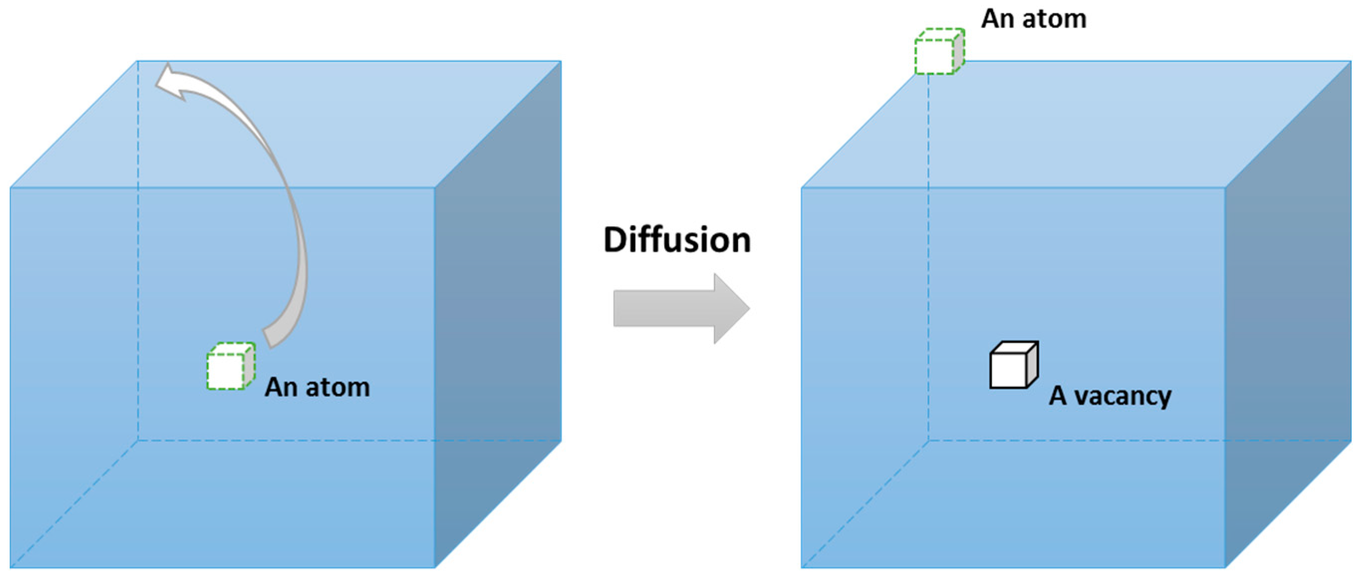
The first term in Equation (9) shows full fatigue capacity, and the second term reflects the strain caused by creep effect. Significantly, a linear relationship is presented between temperature and creep-related strain (also applied plastic strain ), which is consistent with underlying creep mechanism. According to description of four different creep mechanisms (Nabarro-Herring creep, Coble creep, grain boundary sliding and dislocation creep) in Section 3.1, in the present work, diffusion creep (including Nabarro-Herring creep and Coble creep) is regarded as the main creep mechanism for creep fatigue since it has strong temperature dependency. Therefore, the discussion of temperature-strain relation is built on the mechanism of diffusion. As mentioned in Section 3.1, the process of diffusion is identified as a thermodynamic system. In this case, a piece of crystal containing n atoms is selected, wherein an atom inside is transferred to the surface due to diffusion (Figure 3), and thus a vacancy is formed. Normally, the creep process can be described by Gibbs free energy [50]. This parameter shows the thermodynamic potential to form this vacancy under the situation with a given pressure and a given temperature, is presented by Equation (10).
where is the Gibbs free energy for formation of a vacancy, is the change in internal energy due to formation of a vacancy, is the volume of a vacancy, is the entropy for formation of a vacancy, is the pressure and is the temperature. If vacancies are formed during the process of diffusion, the total change in free energy is presented by Equation (11):
where is the total change in free energy, and is the configurational entropy (Equation (12)) which reflects W different ways of distribution of vacancies among the n sites.
where k is the Boltzmann’s constant. Then, the free energy shown by Equation (11) is reorganized as:
By using Stirling’s equation:
Equation (13) can be simplified and approximated as Equation (15) through assuming :
This equation shows that the total free energy has a vacancy-number dependency, and thus this free energy varies during the process of transfer. Normally, the minimum value occurs at the two ends of movements, where an equilibrium situation is achieved and is numerically presented through letting . Then, this operation gives the equilibrium atomic fraction of vacancies:
Normally, diffusion is always described by Fick’s law [3,37,39]:
where is the diffusion flux which shows the amount of substance flowing across a unit area, is the diffusion coefficient, is the position, and reflects the concentration of vacancies and is defined as the number of vacancies per unit volume (Equation (18)):
where is the atomic volume. Therefore, a proportional relation between diffusion flux and temperature component can be presented:
Since creep process indicates that diffusion finally leads to overall deformation, the strain caused by creep effect is proportional to temperature dependency:
The expression of can be simplified as a linear dependency when temperature is relatively high enough and within the application range (normally the range of experimental investigation), such as the temperature range from 650 K to 1000 K for the GP91 casting steel [30].
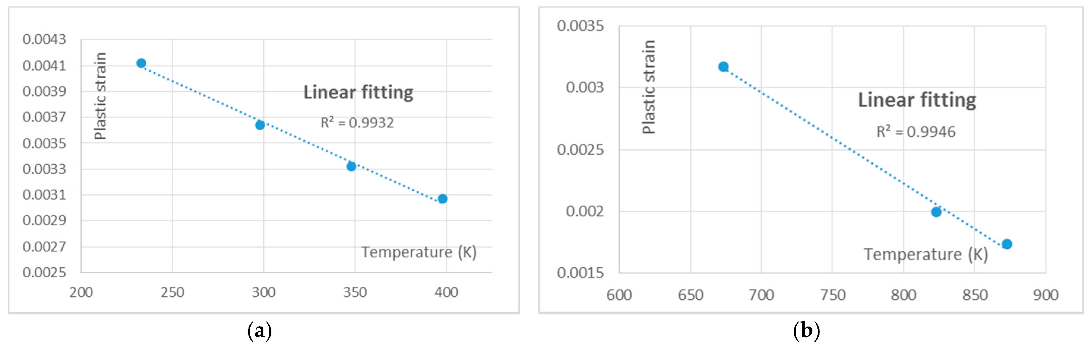
Therefore, we conclude that the underlying physical phenomenon is that diffusion of atoms is based on considerations of free energy and formation of vacancies. The literature shows that this mechanism is represented by an exponential dependency of the form . We propose that the underlying physical explanation is that the ability of an atom to diffuse is based on the volume of space containing vacancies that it can recruit (hence an exp relationship), and on the rate at which vacancies form within that space. The latter requires activation energy, hence is dependent on temperature to achieve the necessary mobility at the atomic level. The formation of vacancies is therefore retarded at low temperatures, becomes active at intermediate temperatures, and is saturated at sufficient high temperature (all available vacancies have been formed), hence the form of the relationship. At sufficiently high temperature the saturation causes this to simplify to a linear relation. This relation is also consistent with the empirical data on the materials of 63Sn37Pb solder [21] and GP91 casting steel [30]. The data on these two materials at the life of 5000 cycles are tabulated in Table 1. Then, the linear relationship between temperature and strain is presented in Figure 4. Results show good quality of linear fitting, with R2 = 0.9932 for 63Sn37Pb solder and 0.9946 for GP91 casting steel.
Therefore, the creep-related strain is linearly proportional to temperature, and the overall fatigue capacity is reduced by a thermal effect, hence giving rise to the term in the unified formulation.
4.2. Logarithmical Relation between Temperature and Cyclic Time
A logarithmical relation between temperature and cyclic time is presented by the unified creep-fatigue equation, which is consistent with creep mechanism. As shown in Section 4.1, the diffusion behavior gives the logarithmical relationship between temperature and diffusion flux (Equation (19)). The definition of “diffusion flux” indicates that this term measures the amount of substance flowing through a cross sectional area during a unit time. In this context, it is a measure of the strain rate, at the microstructural level. Thus, a time dependency is included into this parameter in the form of a rate function. Then, Equation (19) can be presented as:
where reflects the amount of substance following through a unit area. Significantly, Equation (21) gives a logarithmical relation between temperature and cyclic time (unite time), and this is consistent with the relationship shown in the unified creep-fatigue equation.
Theoretically, the temperature and cyclic time effects both decrease the fatigue capacity. In this case, we propose that to a first approximation they are independent of each other rather than convoluted with each other, hence the overall effect is additive. However, this statement is only reasonable when the creep damage is not specified. If creep is included then temperature can be related to time under one specific damage to show an inversely proportional relation. For example, for one specific creep damage, the effect caused by increasing temperature could be compensated through decreasing cyclic time. Consequently, considering these two situations, the numerical representation of creep effect is given as the sum of the temperature and cyclic time effects, hence of the form: .
The logarithmical relation for cyclic time is also represented by the conventional time-temperature parameter, wherein the time dependence is addressed as rupture time. This is based on the integrated characteristic shown by the unified creep-fatigue model. Specifically, the integrated characteristic shows that the unified creep-fatigue equation can be reorganized to the Manson-Haferd parameter at the pure-creep condition, where a logarithmical temperature-time relation is accommodated. Although this time-temperature parameter was entirely derived from empirical data (no physical basis) [32], it has been successfully validated on different materials, and thus is believed to have ability to describe creep behaviors. In addition, the pure-creep condition could be regarded as the idealization of a creep-fatigue situation with extremely prolonged cyclic time. In this case, it is reasonable for the unified formulation to present creep mechanism in a logarithmical relation between temperature and cyclic time.
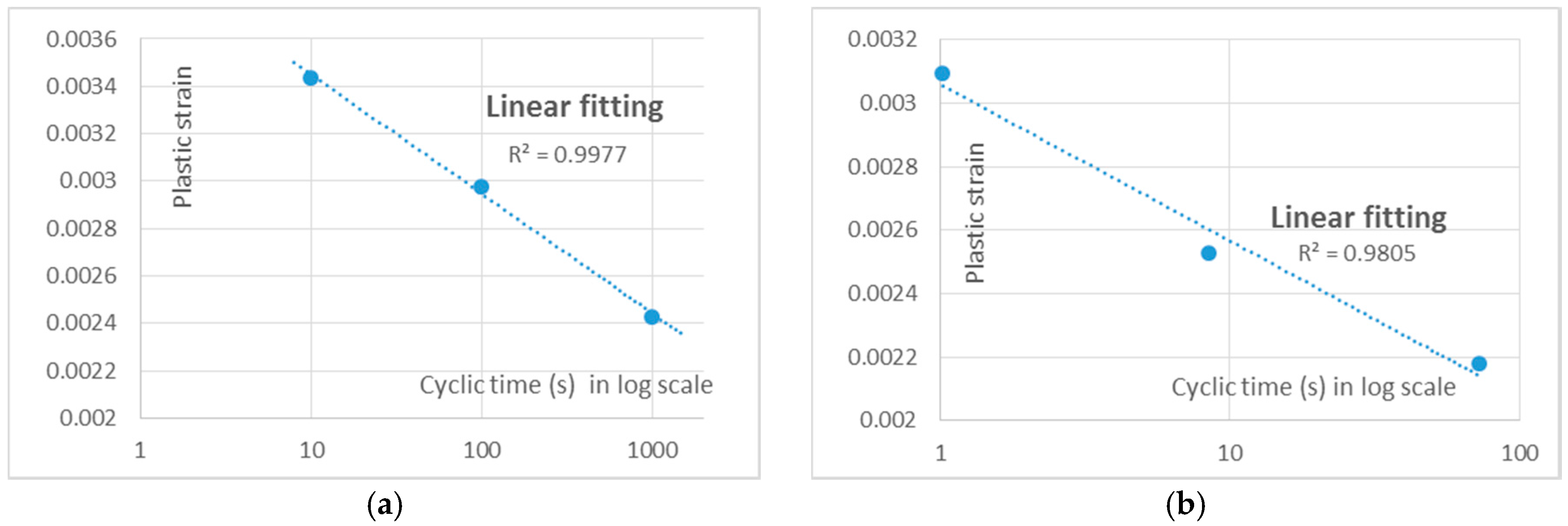
In the specific case of cyclic creep, the load fluctuates between tension and compression. The cyclic time is a measure of the duration of time to which the material is exposed to the diffusion flow under tension and compression. Under tensile loading, we propose that the flow is, in practice, limited by dislocation pinning, grain boundaries, and other flow-limiting effects at the microstructural level. This causes the rate of diffusion to be reduced over longer periods, hence the total plastic strain due to this component has the form . This logarithmical relation between plastic strain and cyclic time is also consistent with empirical data on the materials of 63Sn37Pb solder [21] and stainless steel 316 [51]. The creep-fatigue data for the materials at the life of 5000 cycles are tabulated in Table 2, and the curve-fitting results are then presented by Figure 5. The result illustrates a good linear fit between strain and log of cyclic time, which implies a logarithmical relation between cyclic time and plastic strain.
When the cycle is reversed, and the load moves into the compression stage, the diffusion is not undone (reversed). This is because changes have occurred at the microstructural level such that it is not the same geometric system as before—the system is inelastic. Consequently, the compression part of the cycle does not completely undo the inelastic strain of the previous stage (during a limited time range imposed for general engineering case). Also, the compression is proposed to undo or at least disturb the flow-limiting effects that arose in the tension stage. Hence the next tension cycle permits further diffusion to occur. We therefore propose that the cyclic time reduces the fatigue capacity per . Although the cycle time provides a limited opportunity for the creep effect to operate, it is still reasonable to assume that the amount of creep that occurs within one part of the cycle follows the logarithmic time-temperature dependency.
Therefore, the diffusion-creep behavior is physically described by the amount of substance (which is logarithmical with temperature) flowing through a specific area during a unit time, thus this gives a logarithmical relation between temperature and time.
4.3. Power-Law Relation between Grain Size and Strain
The derivation of the unified creep-fatigue equation shows that the grain-size component is imposed into creep-related component and is directly extracted from the general creep equation for steady state [32], wherein a power-law relation between creep-related strain and grain size is presented (Equation (9)). This relation appears to accurately represent creep behavior.
Generally, diffusion flux for creep behavior is numerically formulated by Fick’s equation (Equation (17)). A microstructural-level-based discussion shown in Section 4.1 shows that diffusion flux is not only related to the time, but also related to the unit area where substance following through (Equation (22)):
where reflects the amount of substance following during a unit time and is the area where substance following through. This area can be obtained by the product of number of grains in unit area and average area of grain, wherein the average area has a strong dependency on grain size. Generally, the area of geometry can be numerically related with the key dimension in the form of second power order. In the present work, a complex situation for creep-fatigue condition is presented, wherein creep and fatigue are coupled, and this may cause the intensity of grain-size effect to deviate from the power of two, but the power-law relation should remain. Consequently, based on the general creep mechanism, it is logical that a power-law relation between grain size and strain is presented in the unified formulation.
In addition, bigger grain size is always beneficial for pure creep. This grain-size effect on creep is consistent with the presentation of the unified creep-fatigue equation. According to the validations [25] on the materials of Inconel 718 and GP91 casting steel, the negative exponent to grain size shows the benefit of big grain size on creep resistance.
We propose that the physical explanation for the grain-size dependency is that the diffusion creep phenomenon involves effects at the (irregular) grain boundaries, and to a lesser extent movement within the crystalline structure of the grain. However the latter mechanism becomes stalled once the available dislocations have run their courses. Hence the steady creep loading purges the internal structure of the grain of imperfections. Consequently the larger the grain, the lower the opportunity for diffusion creep to occur. Thus, it is to be expected that plastic strain would be inversely related to grain size, hence m is negative in . For very small grains the effect becomes disproportionately worse, because a small change in grain size results in a large change in the number of grains in the section. This means more grain boundaries and opportunity for creep. A similar change in size for a large grain has a much smaller effect.
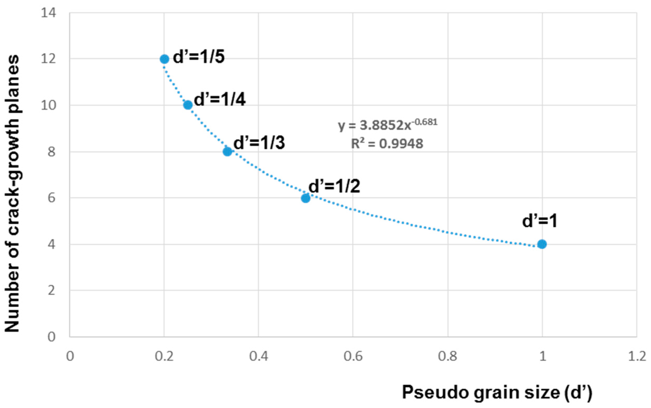
We note that m is approximately −0.5 for both materials considered (Inconel 718 and GP91 casting steel). Since creep damage involves crack propagation along a grain boundary, the decreased grain size results in increased opportunity for crack growth within a given area. For example, one square grain is identified to have four sides, hence four crack-growth potentials, then halving or quartering of grain size gives two more or six more potential directions for crack growth respectively for the same total area. Note that the size of one square grain is a reference condition, based on which the grain is halved or quartered. In this case, the grain size of 1 is not specified as 1 µm, but should rather be considered as a mathematical origin for the scaling effect, hence we refer to this as the pseudo grain size. The relationship between pseudo grain size d’ and the number of crack-growth planes is shown in Figure 6. This relationship may be formulated numerically as a power-law relation, with exponent −0.68. In practical situations, the grain boundaries are not flat planes but are instead more irregular. The effect of this is to (a) increase the planar area available, and (b) provide more opportunity for an element of the boundary to be aligned with the preferred crack-growth direction. Hence practical situations are expected to provide greater opportunity for crack growth as the grain size decreases. The effect of this is to change the exponent closer to zero, e.g., if there were two additional planes at each stage then the exponent becomes −0.523.
We therefore propose that there are natural reasons for the exponent in the formulation to be of the order m = −0.681 or larger, and this is compatible with the empirically determined values of m = −0.5411 for Inconel 718 and m = −0.4053 for GP91 casting steel.
4.4. Power-Law Relation between Life and Strain
The derivation of the unified creep-fatigue equation shows an extension of the Coffin-Manson equation. Therefore, the power-law relation shown in the Coffin-Manson equation is accommodated in the unified formulation. It is acceptable that the power-law relation between reversed loading and number of cycles could well present the process of damage accumulation in fatigue perspective.
In the present work, fracture mechanics is presented as an opening model showing direct apart between two crack surfaces, per [52]. Therefore, the stress intensity factor () is shown by Equation (23):
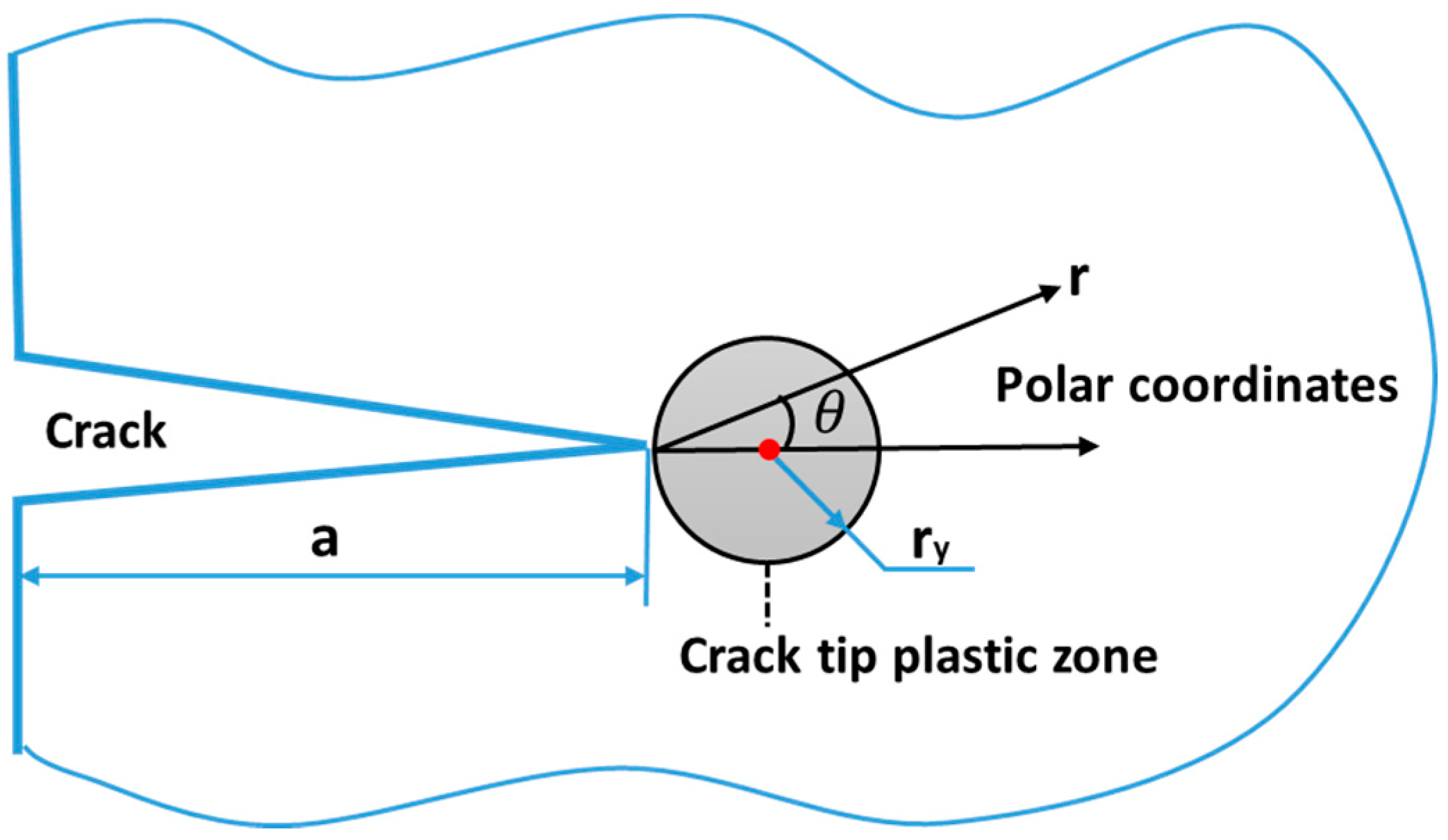
where is the applied stress and is the crack length. Crack-growth process shows that plastic deformation occurs around the crack tip due to high stress concentration, where a circular plastic zone ahead of the crack tip is formed (Figure 7). According to the definition of the stress intensity and Equation (23), the stress distribution () near the crack tip is:
where and are polar coordinates. This equation shows that when r tends towards zero, the stress around the crack tip becomes singular. This implies the existence of a plastic zone, with yield stress () presented at the boundary of this zone. Then, through letting and , Equation (25) gives the size of plastic zone [52]:
where is the radius of the plastic zone.
At the situation with cyclic loading, the stress intensify factor in Equation (25) varies with the change of loading, and then results in expansion or shrinkage of the plastic zone. In this case, the effective stress intensify factor ( or ) is introduced and is given as:
where is the difference between maximum () and minimum () stress intensify factors for one cycle. Then, an equivalent radius of the plastic zone () can be given by Equation (27):
This equation shows that the second power order in Equation (25) is reasonably replaced by a general exponent (n) due to the equivalent transformation, which is consistent with FEA result shown by You [53]. Since larger plastic zone gives more crack growth [52], the crack growth in one cycle can be related with in a power-law relation. This relation (Equation (28)) was initially presented by Paris [3] and then demonstrated amounts of empirical data [54,55].
where gives the increased crack length in one cycle, and C and m are constants. According to Equation (23), effective stress intensify factor also can be expressed as:
where X is a constant and is the stress range. Then, introducing Equation (29) into Equation (28) gives:
Applying the integral operation for life gives [56]:
where is the critical crack length at which fracture occurs and is the initial crack length at which crack starts to grow under a given stress range. Significantly, this equation shows a typical power-law relation between fatigue life and applied stress range (applied loading), and thus it is also reasonable to relate plastic strain with fatigue life in a power-law relation.
Therefore, the existence and size of the plastic zone at crack tip are the physical basis for the power-law relation for crack growth. It is reasonable to assume that fatigue damage is accumulated at each cycle by the same form. This results in a power-law relation between applied loading and life, hence explaining the form .
4.5. Numerical Presentation of Creep Effect on Fatigue Capacity
The development of the strain-based unified creep-fatigue equation is based on the concept of “fatigue capacity” [26,27]. Briefly, this concept physically indicates that the full fatigue capacity is gradually consumed by the creep effect, and this process is numerically presented by the form of (1 − x). This form is accommodated in the unified creep-fatigue formulation (Equation (1)).
Equation (9) shown in Section 3.1 indicates that the first term reflects the full fatigue capacity wherein the fatigue behavior under the pure-fatigue condition is presented by the Coffin-Manson equation. In addition, the second term of Equation (9) describes the creep-related effect, where temperature, cyclic time and grain size dependencies are included. This term takes a Coffin-Manson-type formulation, and shows the creep-related damage is accumulated at cyclic loading. The combination of these two terms is numerically presented as the form of “1 − x” (Equations (1)) and shows the gradual consumption of full fatigue capacity due to creep effect where the residual fatigue capacity is given.
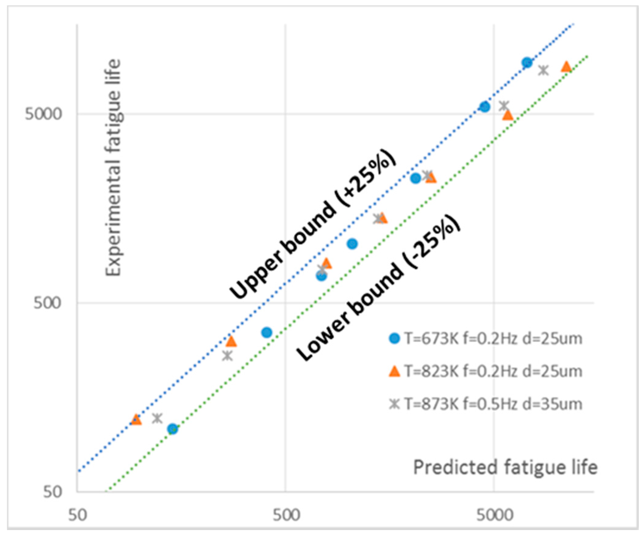
In addition, the reference condition is introduced to show the threshold between pure fatigue and creep fatigue, and creep effect is dormant below the reference condition. At the reference condition, the full fatigue capacity is presented (the second term of Equation (9) equals to zero) in the form of the Coffin-Manson equation. Therefore, the introduction of the reference condition builds a bridge between pure fatigue and creep fatigue. The ability to describe the pure-fatigue condition is proved on the material of GP91 casting steel, where the ratios of predicted fatigue life (obtained by the degenerated form of the unified model) to experimental result (extracted from [30]) fall within the upper bound (+25%) and the lower bound (−25%) (Figure 8). This implies that the unified formulation provides a good quality prediction of fatigue-life under the pure-fatigue condition, specifically a relatively high correlation between predicted and experimental fatigue life.
Consequently, the negative effect of creep on fatigue capacity is numerically formulated as the form of (1 − x), and the introduction of the reference condition shows the threshold for the activation of creep effect.
5. Discussion
5.1. Summary
In summary, we propose the following fundamental mechanisms are at work to determine the creep-fatigue behavior of a material; see Figure 9. In this way we propose that the main structural features of the unified creep-fatigue equation are grounded in deeper physical phenomena.
5.2. Limitations and Future Work
The discussion shown above indicates that the relationships between different variables in the unified creep-fatigue formulation are consistent with underlying physical mechanisms, thus this creep-fatigue model has the ability to describe creep-fatigue behavior numerically and also in terms of physical meaning. Although the relationships between different parameters were derived from underlying physical phenomena, the numerical values of the coefficients still cannot be predicted with precision. In this case, the coefficients need to be extracted through performing creep-fatigue experiments. This is a limitation for this unified formulation, which implies that the coefficients cannot be predicted without any empirical data of fatigue. This model has an opportunity to be further modified/improved to reduce the dependence on fatigue tests, by exploring for more convenient and economical data collection methods.
Generally, reducing the dependence on fatigue test could be conducted through introducing the material-property-related parameters, such as yield strength, into the coefficients. By this means, the coefficients could be directly evaluated through the material properties, and the fatigue test would be eliminated. This work was initially attempted by Manson [57], who proposed a universal slope formulation for the strain-life relation through introducing the parameter of ductility. This provides a possible method to improve this limitation. In addition, this limitation also could be improved by deeper investigation into physical phenomena of fatigue and creep. For example, the grain-size related coefficients may be related to crystal structure, and the creep-related coefficients may be physically represented through quantitatively investigating the influences of temperature and time on creep-fatigue damage presented by the behaviors of diffusion or thermodynamics.
It is notable that although the new creep-fatigue model is not completely free of the need for empirical data, the method of derivation makes this model fundamentally superior to other existing creep-fatigue models (mentioned in Section 1) because of the good balance between accuracy and economy. The accuracy of fatigue-life prediction has been proved on multiple materials in previous research [25,26,27]. The good economy of the current model means fewer creep-fatigue data are required to determine the coefficients.
6. Conclusions
Creep-fatigue behavior is normally influenced by temperature, cyclic time and grain size. Generally, the fatigue capacity is gradually consumed by elevated temperature and prolonged cyclic time, and smaller grain size results in better fatigue capacity, but leads to worse creep resistance. These relevant variables are well accommodated in the unified creep-fatigue equation, and the relationships between them are con with underlying physical mechanisms of fatigue and creep. Specifically, the creep-related relationships, including linear relation between temperature and strain, logarithmic relation between temperature and cyclic time and power-low relation between grain size and strain, are extracted from diffusion-creep phenomenon. In addition, crack-growth behavior gives a power-law relationship between life and strain. Finally, based on the concept of fatigue capacity, these physical-mechanism-based relationships are numerically constructed in the form of “1 − x”, and the reference condition is introduced to present the threshold of creep effect.
The original contribution of this work is that the unified creep-fatigue equation is linked to physical phenomena at a microstructural level. Specifically, the influences of different variables (including temperature, cyclic time and grain size) on creep-fatigue behavior were explored, and the numerical relationships shown in this equation were investigated and explained through proposed deeper physical mechanisms of fatigue and creep. A particular contribution is the proposition of a physical explanation of the grain-size exponent (m) via consideration of crack-growth planes.
Author Contributions
The work was conducted by D.L. and supervised by D.J.P. The investigation of physical-mechanism-based relationships from a microstructural level was conducted by D.L. The explanation of how relevant variables influence creep fatigue was conducted by D.L. and D.J.P. All authors contributed to writing the paper.
Conflicts of Interest
The authors declare no conflict of interest.
References
- Miner, M.A. Cumulative damage in fatigue. J. Appl. Mech. 1945, 12, 159–164. [Google Scholar]
- Palmgren, A. Die lebensdauer von kugellagern. Z. Ver. Dtsch. Ing. 1924, 68, 339–341. [Google Scholar]
- Paris, P.; Erdogan, F. A critical analysis of crack propagation laws. J. Basic Eng. 1963, 85, 528–533. [Google Scholar] [CrossRef]
- Takahashi, Y. Study on creep-fatigue evaluation procedures for high-chromium steels—Part I: Test results and life prediction based on measured stress relaxation. Int. J. Press. Vessel. Pip. 2008, 85, 406–422. [Google Scholar] [CrossRef]
- Takahashi, Y.; Dogan, B.; Gandy, D. Systematic evaluation of creep-fatigue life prediction methods for various alloys. J. Press. Vessel. Technol. 2013, 135, 061204. [Google Scholar] [CrossRef]
- Payten, W.M.; Dean, D.W.; Snowden, K.U. A strain energy density method for the prediction of creep-fatigue damage in high temperature components. Mater. Sci. Eng. 2010, 527, 1920–1925. [Google Scholar] [CrossRef]
- Neu, R.; Sehitoglu, H. Thermomechanical fatigue, oxidation, and creep: Part II. Life prediction. Metall. Trans. A 1989, 20, 1769–1783. [Google Scholar] [CrossRef]
- Ainsworth, R.; Ruggles, M.; Takahashi, Y. Flaw assessment procedure for high-temperature reactor components. J. Press. Vessel. Technol. 1992, 114, 166–170. [Google Scholar] [CrossRef]
- Cailletaud, G.; Nouailhas, D.; Grattier, J.; Levaillant, C.; Mottot, M.; Tortel, J.; Escavarage, C.; Héliot, J.; Kang, S. A review of creep-fatigue life prediction methods: Identification and extrapolation to long term and low strain cyclic loading. Nucl. Eng. Des. 1984, 83, 267–278. [Google Scholar] [CrossRef]
- June, W. A continuum damage mechanics model for low-cycle fatigue failure of metals. Eng. Fract. Mech. 1992, 41, 437–441. [Google Scholar] [CrossRef]
- Chaboche, J.L. Une loi Différentielle D’endommagement de Fatigue avec Cumulation non Linéaire; Office Nationale d’Etudes et de Recherches Aérospatiales: Palaiseau, France, 1974.
- Metzger, M.; Nieweg, B.; Schweizer, C.; Seifert, T. Lifetime prediction of cast iron materials under combined thermomechanical fatigue and high cycle fatigue loading using a mechanism-based model. Int. J. Fatigue 2013, 53, 58–66. [Google Scholar] [CrossRef]
- Seifert, T.; Riedel, H. Mechanism-based thermomechanical fatigue life prediction of cast iron. Part I: Models. Int. J. Fatigue 2010, 32, 1358–1367. [Google Scholar] [CrossRef]
- Charkaluk, E.; Bignonnet, A.; Constantinescu, A.; Dang Van, K. Fatigue design of structures under thermomechanical loadings. Fatigue Fract. Eng. Mater. Struct. 2002, 25, 1199–1206. [Google Scholar] [CrossRef]
- Constantinescu, A.; Charkaluk, E.; Lederer, G.; Verger, L. A computational approach to thermomechanical fatigue. Int. J. Fatigue 2004, 26, 805–818. [Google Scholar] [CrossRef]
- Basquin, O. The Exponential Law of Endurance Tests; ASTM International: West Conshohocken, PA, USA, 1910; pp. 625–630. [Google Scholar]
- Coffin, L.F., Jr. A Study of the Effects of Cyclic Thermal Stresses on a Ductile Metal; Knolls Atomic Power Lab.: Niskayuna, NY, USA, 1953. [Google Scholar]
- Manson, S.S. Behavior of Materials under Conditions of Thermal Stress; Lewis Flight Propulsion Lab.: Cleveland, OH, USA, 1954. [Google Scholar]
- Coffin, L. Fatigue at high temperature. In Fatigue at Elevated Temperatures; ASTM International: West Conshohocken, PA, USA, 1973. [Google Scholar]
- Solomon, H. Fatigue of 60/40 solder. IEEE Trans. Compon. Hybrids Manuf. Technol. 1986, 9, 423–432. [Google Scholar] [CrossRef]
- Shi, X.; Pang, H.; Zhou, W.; Wang, Z. Low cycle fatigue analysis of temperature and frequency effects in eutectic solder alloy. Int. J. Fatigue 2000, 22, 217–228. [Google Scholar] [CrossRef]
- Jing, H.; Zhang, Y.; Xu, L.; Zhang, G.; Han, Y.; Wei, J. Low cycle fatigue behavior of a eutectic 80 au/20 sn solder alloy. Int. J. Fatigue 2015, 75, 100–107. [Google Scholar] [CrossRef]
- Engelmaier, W. Fatigue life of leadless chip carrier solder joints during power cycling. IEEE Trans. Compon. Hybrids Manuf. Technol. 1983, 232–237. [Google Scholar] [CrossRef]
- Wong, E.; Mai, Y.-W. A unified equation for creep-fatigue. Int. J. Fatigue 2014, 68, 186–194. [Google Scholar] [CrossRef]
- Liu, D.; Pons, D. Development of a unified creep-fatigue equation including heat treatment. Fatigue Fract. Eng. Mater. Struct. 2017. [Google Scholar] [CrossRef]
- Liu, D.; Pons, D.; Wong, E.-H. The unified creep-fatigue equation for stainless steel 316. Metals 2016, 6, 219. [Google Scholar] [CrossRef]
- Liu, D.; Pons, D.; Wong, E.-H. Creep-integrated fatigue equation for metals. Int. J. Fatigue 2017, 98, 167–175. [Google Scholar] [CrossRef]
- Manson, S.; Haferd, A. A Linear Time-Temperature Relation for Extrapolation of Creep and Stress-Rupture Data; Lewis Flight Propulsion Lab.: Cleveland, OH, USA, 1953. [Google Scholar]
- Tabuchi, M.; Hongo, H.; Li, Y.; Watanabe, T.; Takahashi, Y. Evaluation of microstructures and creep damages in the haz of p91 steel weldment. J. Press. Vessel. Technol. 2009, 131, 021406. [Google Scholar] [CrossRef]
- Mroziński, S.; Golański, G. Low cycle fatigue of gx12crmovnbn9–1 cast steel at elevated temperature. J. Achiev. Mater. Manuf. Eng. 2011, 49, 7–16. [Google Scholar]
- Liu, D.; Pons, D. A unified creep-fatigue equation with application to engineering design. InTechOpen 2017. under review. [Google Scholar]
- Dowling, N.E. Mechanical Behavior of Materials: Engineering Methods for Deformation, Fracture, and Fatigue; Pearson Education (US): London, UK, 2012. [Google Scholar]
- Shigley, J.E.; Mischke, C.R. Mechanical Engineering Design; McGraw-Hill: New York, NY, USA, 2003. [Google Scholar]
- Ashby, M.F.; Shercliff, H.; Cebon, D. Materials: Engineering, Science, Processing and Design; Butterworth-Heinemann: Oxford, UK, 2013. [Google Scholar]
- Callister, W.D.; Rethwisch, D.G. Materials Science and Engineering; John Wiley & Sons: New York, NY, USA, 2011. [Google Scholar]
- Finnie, I.; Heller, W.R. Creep of Engineering Materials; McGraw-Hill: New York, NY, USA, 1959. [Google Scholar]
- Kassner, M.E. Fundamentals of Creep in Metals and Alloys; Elsevier: Amsterdam, The Netherlands, 2015. [Google Scholar]
- Poirier, J.-P. Creep of Crystals: High-Temperature Deformation Processes in Metals, Ceramics and Minerals; Cambridge University Press: Cambridge, UK, 1985. [Google Scholar]
- Shewmon, P. Diffusion in Solids; Springer: Berlin/Heidelberg, Germany, 2016. [Google Scholar]
- Prokoshkina, D.; Esin, V.; Wilde, G.; Divinski, S. Grain boundary width, energy and self-diffusion in nickel: Effect of material purity. Acta Mater. 2013, 61, 5188–5197. [Google Scholar] [CrossRef]
- Dai, C.; Zhang, B.; Xu, J.; Zhang, G. On size effects on fatigue properties of metal foils at micrometer scales. Mater. Sci. Eng. 2013, 575, 217–222. [Google Scholar] [CrossRef]
- Hanlon, T.; Kwon, Y.-N.; Suresh, S. Grain size effects on the fatigue response of nanocrystalline metals. Scr. Mater. 2003, 49, 675–680. [Google Scholar] [CrossRef]
- Cocks, A.; Pontern, A. Mechanics of Creep Brittle Materials 1; Springer Science & Business Media: Berlin, Germany, 1989. [Google Scholar]
- Ejaz, N.; Qureshi, I.; Rizvi, S. Creep failure of low pressure turbine blade of an aircraft engine. Eng. Fail. Anal. 2011, 18, 1407–1414. [Google Scholar] [CrossRef]
- Král, P.; Dvořák, J.; Kvapilová, M.; Svoboda, M.; Sklenička, V. Creep damage of al and al-sc alloy processed by ecap. In Proceedings of the Acta Metallurgica Slovaca-Conference, Košice, Slovakia, 2012. [Google Scholar]
- Hatanaka, K.; Yamada, T. Effect of grain size on low cycle fatigue in low carbon steel. Bull. JSME 1981, 24, 1692–1699. [Google Scholar] [CrossRef]
- Hattori, H.; Kitagawa, M.; Ohtomo, A. Effect of grain size on high temperature low-cycle fatigue properties of inconel 617. Tetsu-To-Hagane 1982, 68, 2521–2530. [Google Scholar] [CrossRef]
- Pieraggi, B.; Uginet, J. Fatigue and Creep Properties in Relation; The Minerals, Metals & Materials Society: Pittsburgh, PA, USA, 1994. [Google Scholar]
- Thébaud, L.; Villechaise, P.; Cormier, J.; Crozet, C.; Devaux, A.; Béchet, D.; Franchet, J.-M.; Organista, A.; Hamon, F. Relationships between microstructural parameters and time-dependent mechanical properties of a new nickel-based superalloy ad730™. Metals 2015, 5, 2236–2251. [Google Scholar] [CrossRef]
- Fredriksson, H. Solidification and Crystallization Processing in Metals and Alloys; John Wiley & Sons: New York, NY, USA, 2012. [Google Scholar]
- Kanazawa, K.; Yoshida, S. Effect of Temperature and Strain Rate on the High Temperature Low-Cycle Fatigue Behavior of Austenitic Stainless Steels; IAEA: Vienna, Austria, 1975. [Google Scholar]
- Weertman, J. Fatigue crack propagation theories. In Fatigue and Microstructure; ASM: Metals Park, OH, USA, 1979; pp. 279–306. [Google Scholar]
- You, C.; He, B.; Achintha, M.; Reed, P. Numerical modelling of the fatigue crack shape evolution in a shot-peened steam turbine material. Int. J. Fatigue 2017, 104, 120–135. [Google Scholar] [CrossRef]
- Liang, R.; Ji, Y.; Wang, S.; Liu, S. Effect of microstructure on fracture toughness and fatigue crack growth behavior of ti17 alloy. Metals 2016, 6, 186. [Google Scholar] [CrossRef]
- Paggi, M. Crack propagation in honeycomb cellular materials: A computational approach. Metals 2012, 2, 65–78. [Google Scholar] [CrossRef] [Green Version]
- Xiang, Y.; Lu, Z.; Liu, Y. Crack growth-based fatigue life prediction using an equivalent initial flaw model. Part I: Uniaxial loading. Int. J. Fatigue 2010, 32, 341–349. [Google Scholar] [CrossRef]
- Manson, S. A modified universal slopes equation for estimation of fatigue characteristics of metals. J. Eng. Mater. Technol. 1988, 110, 55. [Google Scholar]
Figure 1.
Application of the unified model to predict fatigue life vs. experimental fatigue life for GP91 casting steel, with raw data from physical tests from [29,30].

Figure 2.
The transient-creep-plus-elastic model. Image adapted from Ref. [32].
Figure 2.
The transient-creep-plus-elastic model. Image adapted from Ref. [32].
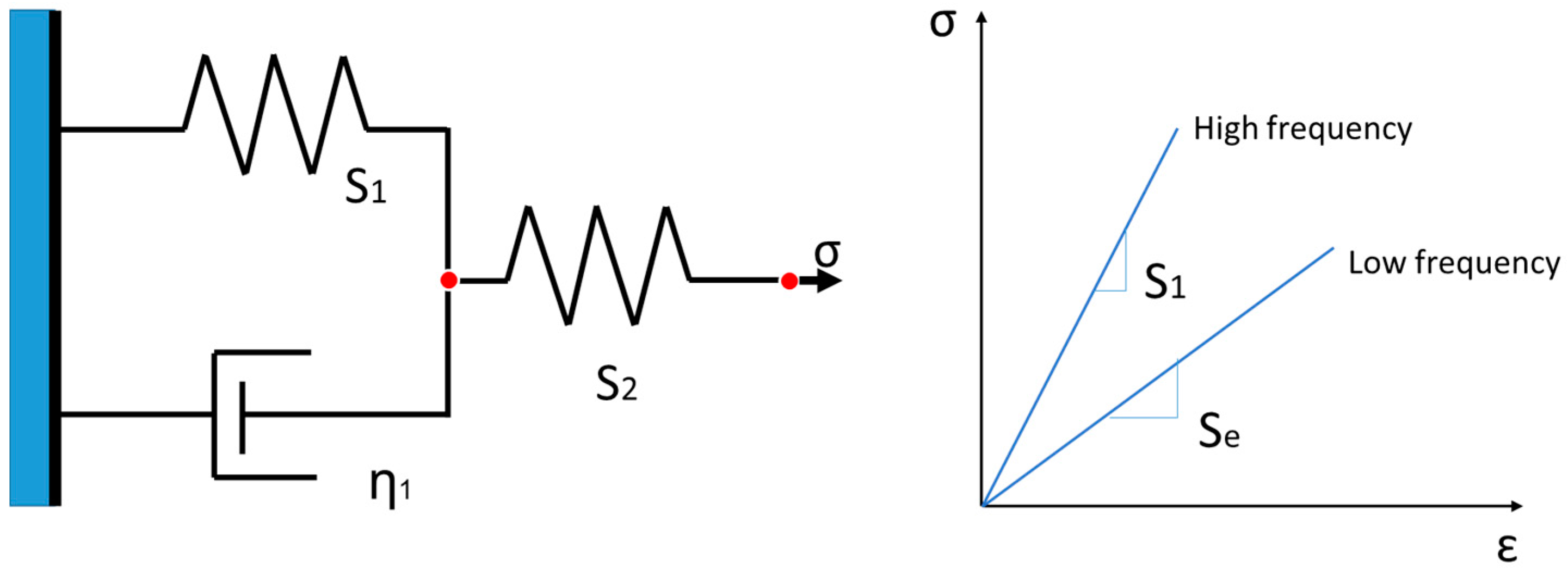
Figure 3.
A movement of an atom.

Figure 4.
Curve fitting of temperature vs. strain for experimental data: (a) 63Sn37Pb; (b) GP91 casting steel. Raw data from [21,30] respectively.

Figure 5.
Curve fitting of log of cyclic time vs. strain for experimental data: (a) 63Sn37Pb; (b) stainless steel 316. Raw data from [21,51] respectively.

Figure 6.
Relationship between pseudo grain size and the number of potential crack-growth planes.

Figure 7.
Plastic zone around crack tip.

Figure 8.
The ratio of predicted fatigue life to experimental result under the pure-fatigue condition, per the unified model, for GP91 casting steel. Raw data from [30].
Figure 8.
The ratio of predicted fatigue life to experimental result under the pure-fatigue condition, per the unified model, for GP91 casting steel. Raw data from [30].
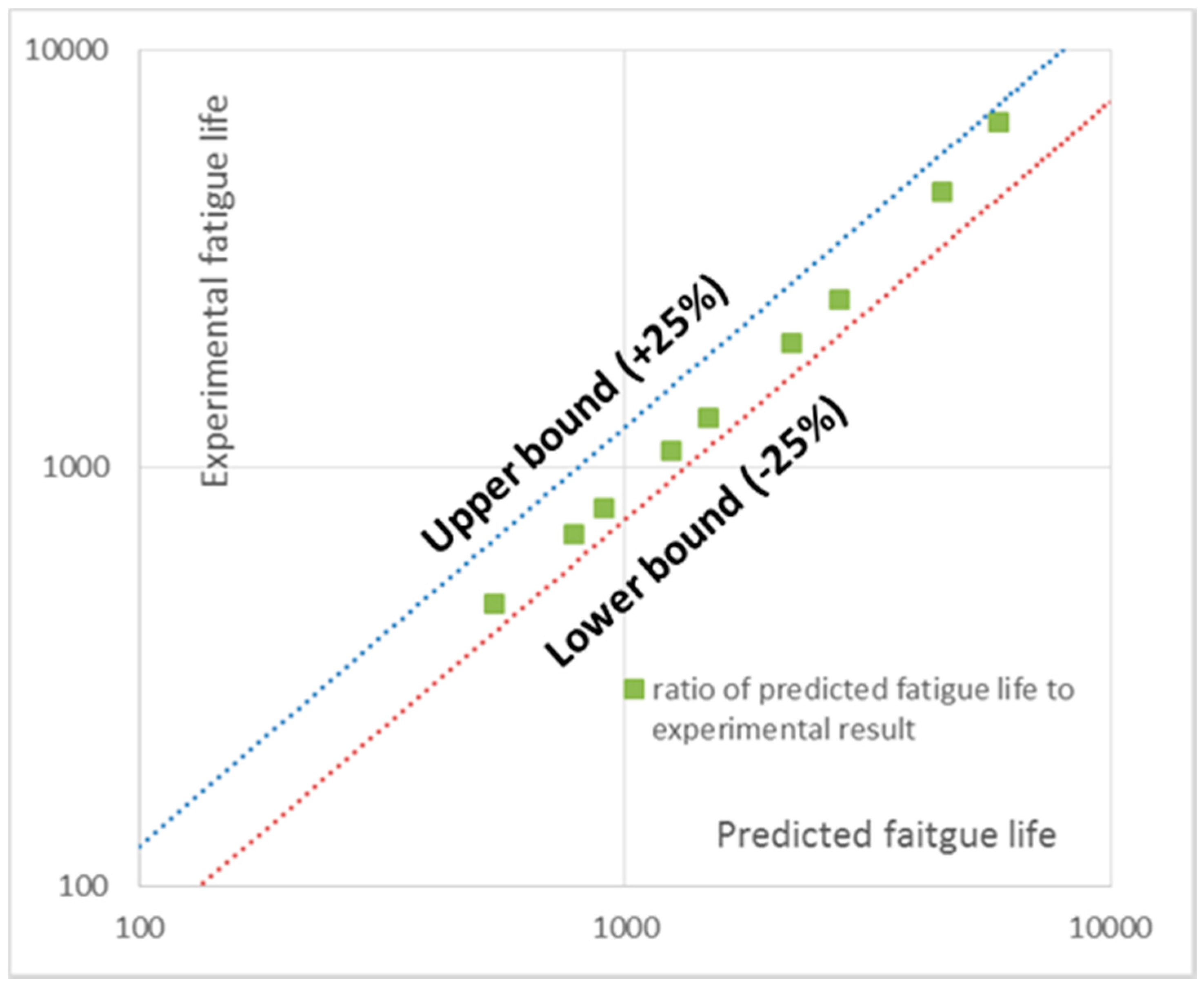
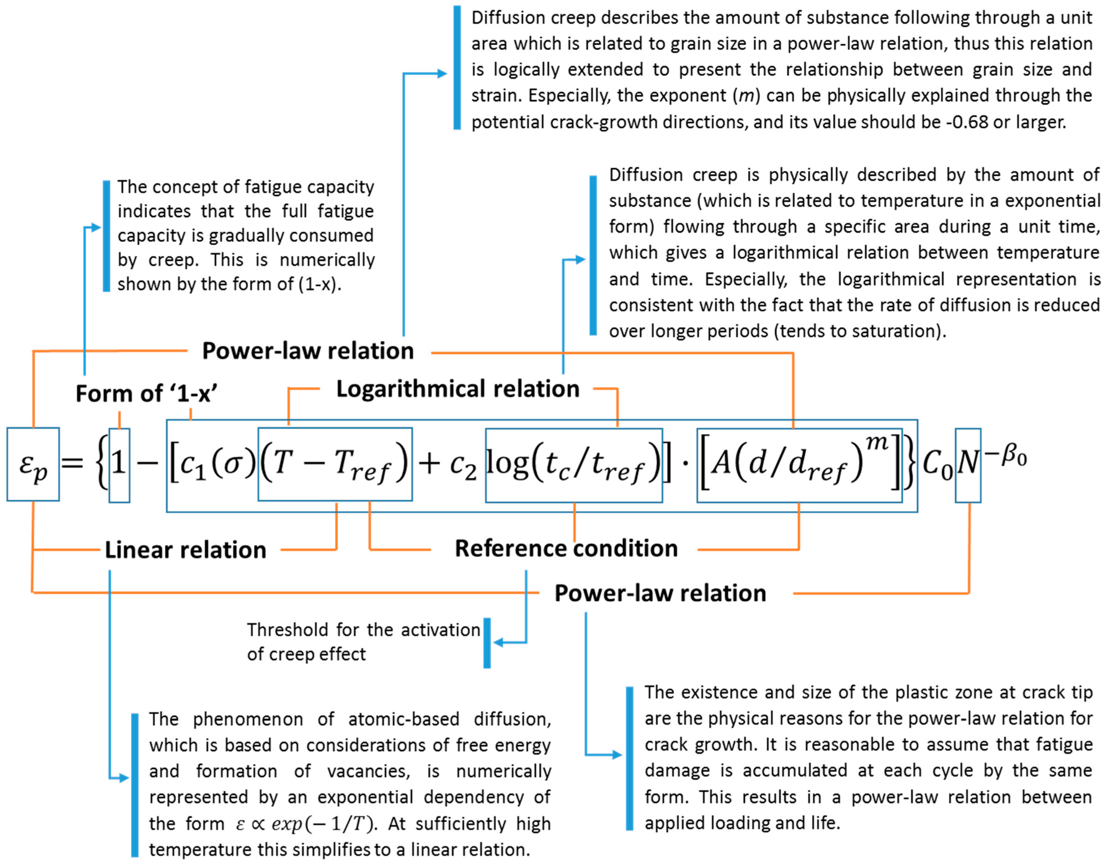
Figure 9.
Main relationships and fundamental mechanisms in the unified formulation.


| Materials | Temperature (K) | Strain | Cyclic Time (s) | Life (Cycles) |
|---|---|---|---|---|
| 63Sn37Pb | 233 | 0.00412 | 1 | 5000 |
| 298 | 0.00364 | |||
| 248 | 0.00332 | |||
| 398 | 0.00307 | |||
| GP91 Casting Steel | 673 | 0.00317 | 20 | 5000 |
| 823 | 0.00199 | |||
| 873 | 0.00174 |
| Materials | Cyclic Time (s) | Strain | Temperature (K) | Life (Cycles) |
| 63Sn37Pb | 10 | 0.00344 | 298 | 5000 |
| 100 | 0.00298 | |||
| 1000 | 0.00243 | |||
| Materials | Strain Rate (%/min) | Strain | Temperature (K) | Life (Cycles) |
| Stainless Steel 316 | 0.4 | 0.00218 | 973 | 5000 |
| 4 | 0.00253 | |||
| 40 | 0.00309 |
© 2017 by the authors. Licensee MDPI, Basel, Switzerland. This article is an open access article distributed under the terms and conditions of the Creative Commons Attribution (CC BY) license (http://creativecommons.org/licenses/by/4.0/).
Share and Cite
MDPI and ACS Style
Liu, D.; Pons, D.J. Physical-Mechanism Exploration of the Low-Cycle Unified Creep-Fatigue Formulation. Metals 2017, 7, 379. https://doi.org/10.3390/met7090379
AMA Style
Liu D, Pons DJ. Physical-Mechanism Exploration of the Low-Cycle Unified Creep-Fatigue Formulation. Metals. 2017; 7(9):379. https://doi.org/10.3390/met7090379
Chicago/Turabian StyleLiu, Dan, and Dirk John Pons. 2017. "Physical-Mechanism Exploration of the Low-Cycle Unified Creep-Fatigue Formulation" Metals 7, no. 9: 379. https://doi.org/10.3390/met7090379
Note that from the first issue of 2016, this journal uses article numbers instead of page numbers. See further details here.