Article

Welding Residual Stress Analysis and Fatigue Strength Assessment of Multi-Pass Dissimilar Material Welded Joint between Alloy 617 and 12Cr Steel

Graduate School of Mechanical Engineering, Sungkyunkwan University, Suwon 440-746, Korea
*
Authors to whom correspondence should be addressed.
Metals 2018, 8(1), 21; https://doi.org/10.3390/met8010021
Submission received: 30 November 2017 / Revised: 26 December 2017 / Accepted: 27 December 2017 / Published: 31 December 2017

Abstract

:
The reliability of welded structure can be evaluated through welding residual stress analysis and fatigue strength assessment. In this study, welding residual stresses of multi-pass dissimilar material welded joint between alloy 617 and 12Cr steel were analyzed numerically and experimentally. Fatigue strength was then assessed in the air. Based on results of welding residual stress analysis and fatigue strength assessment, a fatigue design method considering welding residual stress was investigated. Welding residual stresses at the weld of dissimilar welded joints distributed complicatedly on longitudinal and transverse directions, showing differences but a very similar distribution tendency between numerical and experimental results. Numerical and experimental peak values of welding residual stresses at HAZ of the weld on the 12Cr steel side were predicted to be 333 MPa and 282 MPa HAZ, respectively. The fatigue limit of dissimilar material welded joint between alloy 617 and 12Cr steel was assessed to be 306.8 MPa, which was 40% of tensile strength (767 MPa) of dissimilar material welded joint. However, the stress range including welding residual stress was assessed to be 206.9 MPa, which was 14% lower than that calculated by including the effect of residual stresses.

1. Introduction

It is well-known that the most effective methodology for green power plant systems is to increase the generative efficiency of steam power plants [1]. The core technology for increasing the generative efficiency is to improve the performance of steam turbines. A basic method for improving the performance of thermal power plants is to elevate steam temperature [2]. Therefore, it is necessary to develop suitable materials for extreme environment of power plants. So far, Ni alloys have been candidates as available materials for high temperature steam power plants due to their incredible mechanical properties [3,4]. However, in order to apply Ni alloys (alloy 617 in this paper) to steam turbine materials such as turbine rotor and blades, it is necessary to do dissimilar material welding with the 12Cr steel alloy that is currently used as material for turbine rotor and blades. However, since Inconel alloy 617 and 12Cr steel alloy have different chemical compositions and mechanical properties, reliable welding technology needs to be developed to manufacture hybrid structures that can withstand extreme environmental conditions [4,5]. There are many suitable processes for the joining of dissimilar material as comprehensively summarized by Martinsen et al. [6]. These dissimilar material welded structures often experience variable loadings, ranging from cyclic to completely random fluctuation during their practical working.
Therefore, engineering designers should sufficiently understand the welding metallurgical phenomena, as well as the mechanical properties of the weld, including the mechanism of welding residual stresses generated during the welding process. In particular, as the generation of welding residual stresses is formidable, as well as being the crack driving force of the welded structures, it is very important to understand and assess welding residual stresses in the design process of welded structures. Basically, as welding residual stresses are generated due to repetitive nonlinear thermal loading cycles by the welding heat input, assessing the distribution of these stresses may be too complex to be predicted accurately [7,8]. Residual stresses have a substantial effect on engineering properties of material and welded structures, particularly fatigue strength, corrosion resistance, dimensional stability, and distortion [9]. Many researchers have practiced various methods to measure residual stresses using experimental and numerical methods [10,11,12]. In recent years, as high computational power is available, many researchers have acknowledged the reliability of using the finite element method for this purpose [13,14].
In the present study, the hole-drilling method and the finite element method were used to measure welding residual stresses.
Fatigue is considered the most common cause of failure in welded structures [15]. Dissimilar material welded joints are very sensitive to fatigue stress [16]. Therefore, fatigue testing with varying limits of high stresses can provide very useful information to assess the quality of welded joints [15]. Bae et al. have proposed a σa-r stress range including welding residual stresses by using a modified Goodman equation [17]. Their results showed that fatigue strength, including welding residual stresses, was lower than fatigue strength without considering residual stresses. The objective of the present study was to analyze the welding residual stresses of the multi-pass dissimilar material welded joint between alloy 617 and 12Cr steel, numerically and experimentally. Fatigue strength was then assessed in the air.

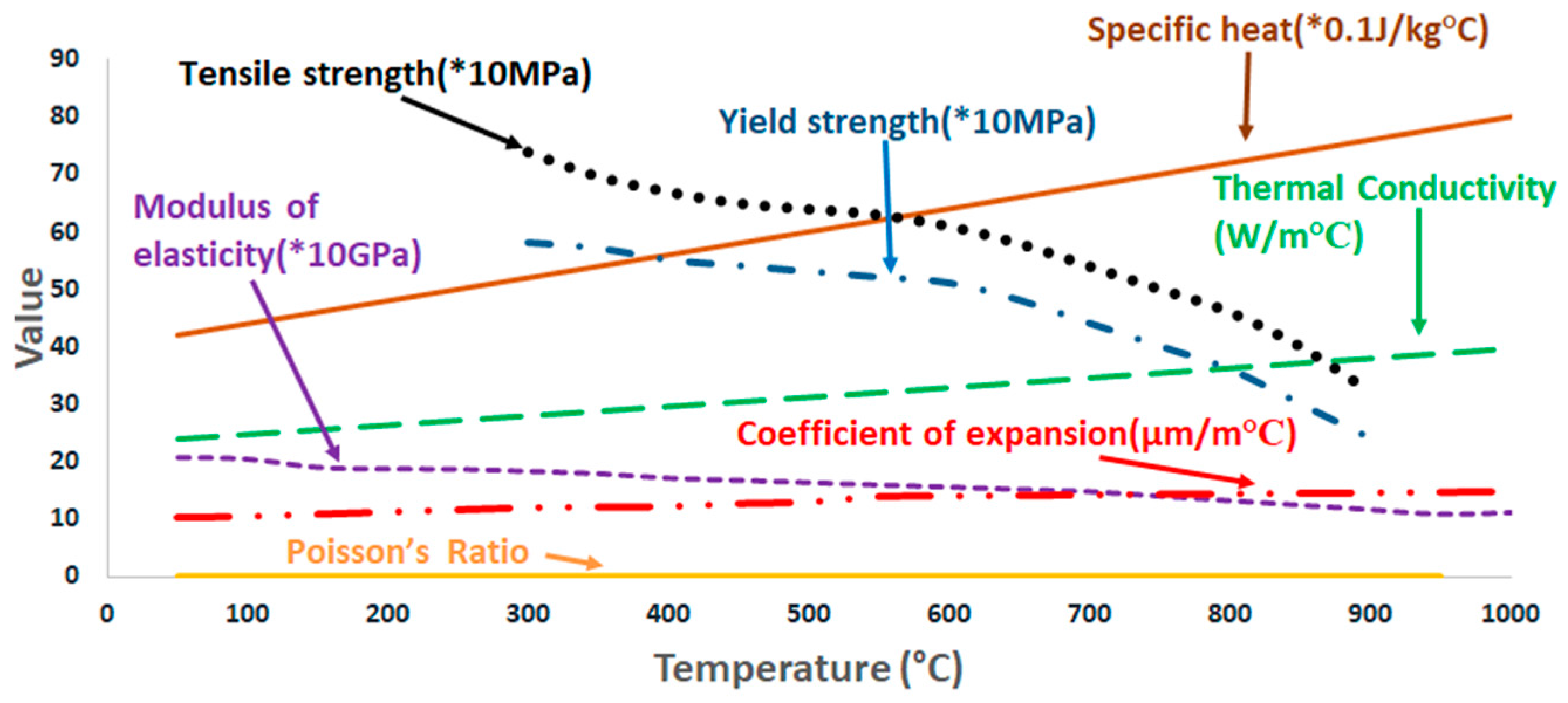
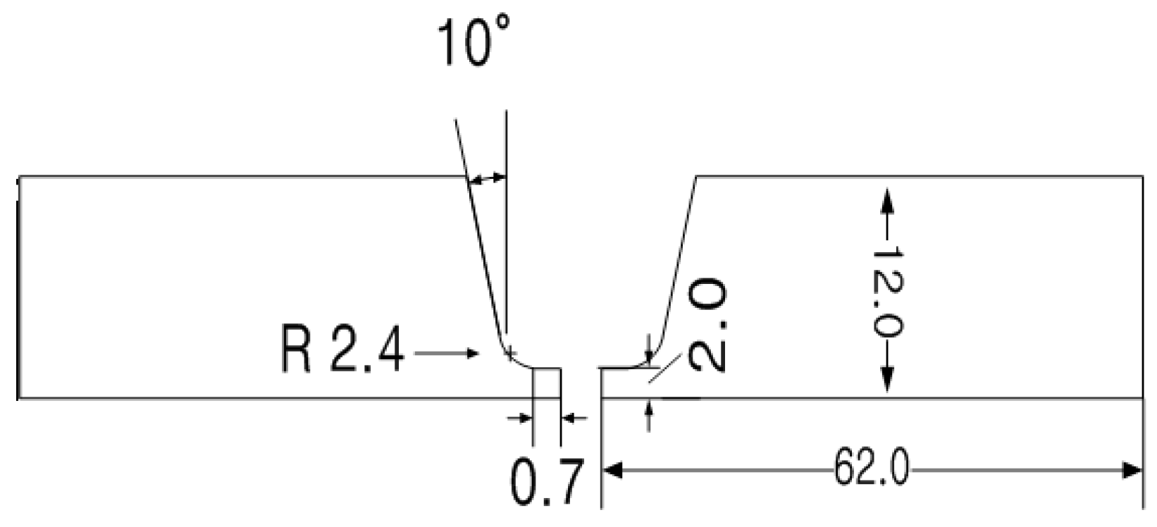
2. Materials and Methods

Materials used for dissimilar material welding included alloy 617 and 12Cr steel alloy. Alloy 617 has good resistance against high temperature and corrosion as it consists of Cr, Mo, and Co as major compositions, while 12Cr steel is being currently used as a material of turbine rotor and blade of steam power plant. Filler material used in this study was Thyssen 617. Its chemical composition is similar to alloy 617. Mechanical properties and chemical compositions of alloy 617, 12Cr steel, and Thyssen 617 are illustrated in Table 1 and Table 2. Multi-pass direct current straight polarity (DCSP) tungsten inert gas (TIG) welding was carried out for multi-pass dissimilar material welding.
Real time monitoring system was used to control welding conditions (electrode shape, electrode to workpiece distance, welding wave form, and welding heat input). Preliminary welding was performed under various welding parameters (i.e., current, voltage, welding speed, shield gas compositions, and flow rates) to determine optimum dissimilar material welding conditions. Obtained optimum welding conditions for dissimilar material are listed in Table 3 [18].
Since the out of plane thermal distortion is formidably caused by welding heat input during the multi-pass welding process, welding jigs were used to fix both ends of base metals to prevent out-of-plane thermal distortion. Multi-pass welding directions were parallel to the rolling direction. U-groove shape was machined for narrow-gap welding [19]. U-groove is economical, as it requires less filler metal, which results in less distortion and residual stress-related problems [20]. Figure 1 shows a welding specimen with U-groove and narrow gap. In the multi-pass welding process, the specimen was cooled down to be under 70 °C in the interval of every welding process. After finishing each pass welding, the ultrasonic testing was carried out following ASTM E164-13 standard to inspect weld defects of multi-pass welds.

3. Residual Stress Analysis of Multi-Pass Dissimilar Material Welded Joint between Alloy 617 and 12Cr Steel

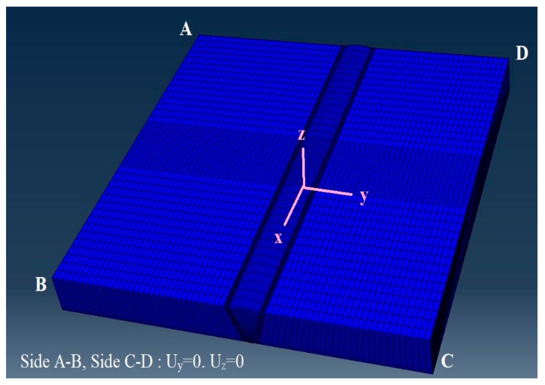
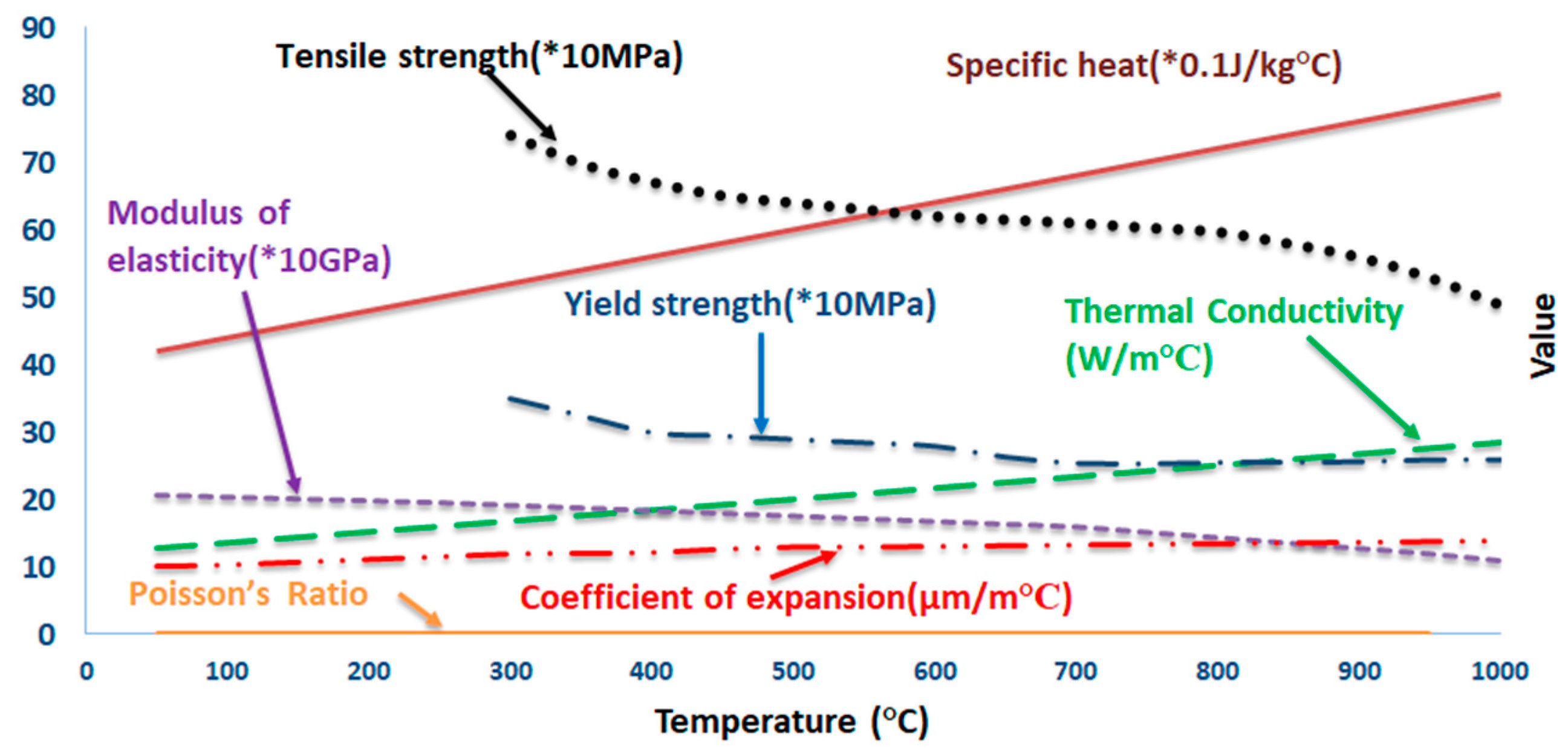
3.1. Numerical Analysis of Welding Residual Stresses

A seven-pass dissimilar material welded plate model shown in Figure 2 was used in this analysis. Its thickness, width, and weld length were 12.7, 300, and 300 mm, respectively. Three-dimensional finite element models were used for both thermal and mechanical analyses with a heat source model. In this study, ramp heat source model was used. For welding, 8-node brick solid elements of type DC3D8 were used. Weld beads of the model represented the weld bead determined from the actual weld condition. Finer meshes were generated in weld metal regions to handle the greater nonlinearity and to obtain accurate results. The total number of elements and nodes were 221,760 and 474,012, respectively. Hyper-mesh® (10.0, Altair, Troy, MI, USA, 2008) was used for mesh generation. ABAQUS (6.10, Dassault Systemes, Johnston, RI, USA, 2010) was employed for transient temperature and subsequent welding residual stress analysis.

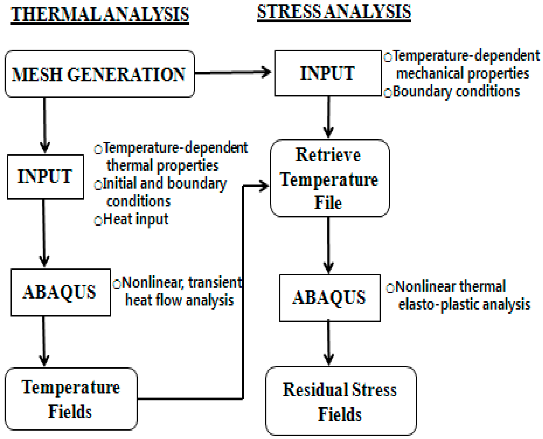
3.1.1. Numerical Analysis Procedure

Uncoupled thermo-mechanical analysis was performed in this study as shown in Figure 3 [21]. Temperature distribution at the weld was analyzed first by thermal analysis. It was then used as input data for stress analysis. Some assumptions were taken into account in the process of thermal-mechanical analysis. When performing the thermal analysis, the initial temperature of base and weld metal was assumed to be a room temperature (25 °C). The conductivity and specific heat in the molten pool were assumed to be constant. Radiation and forced convection due to shielding gas flow were neglected. Since the temperature is very high in the molten pool, radiation and convection can influence microstructures and cooling rates in weld metal. Heat losses or gains from phase transformation were neglected. The volume change effect due to phase transformation was neglected in the stress analysis. Apart from these assumptions mentioned above, in thermal-mechanical analyses for dissimilar material welded model, influences of transient temperature field and temperature-dependent physical properties were considered as input data for accurate and reliable assessment of thermal analysis. When performing the stress analysis, mechanical and physical properties of yield stress, elastic and plastic modules, and thermal expansion coefficient were considered to be temperature dependent. However, mechanical properties were assumed to be constant above the melting point. The temperature dependency of Poisson’s ratio was neglected. Physical and mechanical properties of Alloy 617 and 12Cr steel are given in Figure 4 and Figure 5, respectively [22,23].
The element rebirth technique [24] was applied to simulate the multi-pass weld metal deposition effect. With this technique, elements simulating each weld pass were grouped at the model generation stage. During analysis, these element groups that presented weld passes were first removed and then reactivated at a specified moment to simulate a given deposition sequence of weld passes. When a group of weld elements were activated, specific initial temperatures were imposed at all nodes associated with the weld elements.

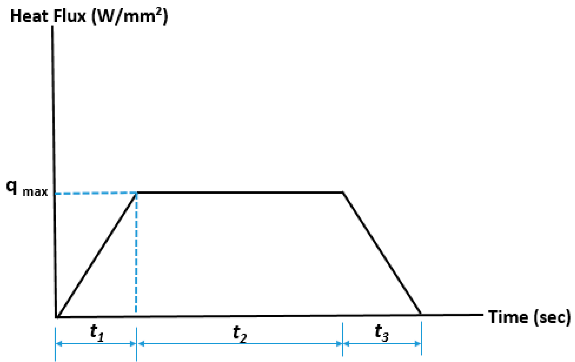
3.1.2. Heat Source Model for Numerical Analysis

In this study, the heat input model using ramp function as shown in Figure 6 based on the concept of Pavelic’s disc model was employed [25,26].
The ramp source heat input model for simulation was used for analysis. Heat flux is expressed in the following equation.
q ( x ) = q ( 0 ) e C x 2
  • q(0): maximum heat flux at the center of heating spot
  • x: distance from the center of heating spot
  • C: heat flux concentration coefficient
In this case, the total amount of heat input is indicated as the combination of surface heat input and body heat input as shown in Equation (2):
Q = Q s + Q b
where
  • Q: total heat input
  • QS: surface heat input
  • Qb: body heat input
The energy input per unit length (H, J/mm) can be shown as Equation (3):
H = Q × 1 v
v: welding speed (mm/s)
Body heat flux ( q b , W/mm3) and surface heat flux ( q s , W/mm2) are indicated in Equations (4) and (5):
q b = Q b V e
q s = Q s b L 3 π e 3 x b 2
where b and L are geometrical parameters of weld bead [25].

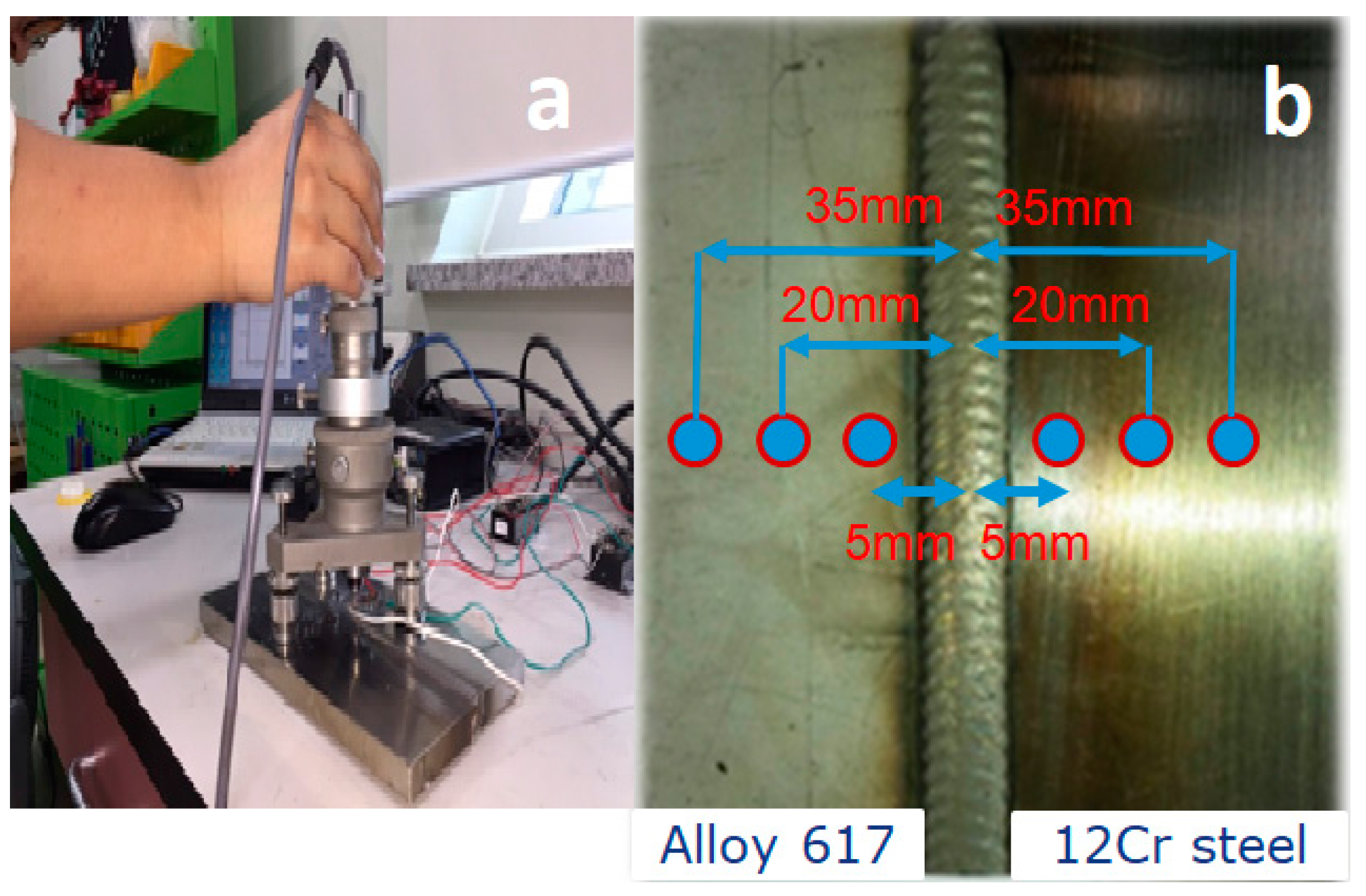
3.2. Experimental Analysis of Welding Residual Analysis

Experimental analysis was performed to calculate welding residual stresses and evaluate results of numerical analysis. In this study, a hole drilling method was used according to ASTM E837 [27]. RS-200 milling guide equipment shown in Figure 7a and strain rosette (Micro measurement Co., EA-06-062RE-120 type, Kyunggi, Korea) were used to measure residual stresses. We analyzed three points (5, 20 and 35 mm) apart from the weld center, respectively, on both sides as shown in Figure 7b. Surfaces of these specimens fabricated by the actual dissimilar material welding between alloy 617 and 12Cr steel were carefully polished to reduce surface roughness error.

3.3. Results and Discussion

The fundamental goal of this study was to develop a reliable FEA model capable of predicting thermal history and residual stresses of dissimilar material weld with higher accuracy. Figure 8 shows comparative results obtained from the FEA developed in this study and experimental analysis. Both results showed quantitatively differences. However, qualitatively, they showed similar tendency. Quantitative difference was due to the fact that temperature-dependent physical properties were not taken into account or neglected by some assumptions. Welding residual stresses were predicted highly at HAZ on both sides of the weld. Residual stresses at the HAZ on the side of 12Cr steel alloy were higher than those of the alloy 617 side. This is due to the fact that Alloy 617 has higher thermal expansion coefficient than 12Cr steel, while thermal conductivity of alloy 617 is lower than that of 12Cr steel.
In longitudinal direction (along the welding direction), numerical peak stress value on the 12Cr steel alloy side was predicted to be 333 MPa. However, the experimental result showed a value of around 282 MPa. In transverse direction (perpendicular to the welding direction), numerical peak stress value on the 12Cr steel alloy side was predicted to be around 306 MPa. However, the experimental result showed a value of around 268 MPa.

4. Fatigue Strength Assessment of Multi-Pass Dissimilar Material Welded Joint

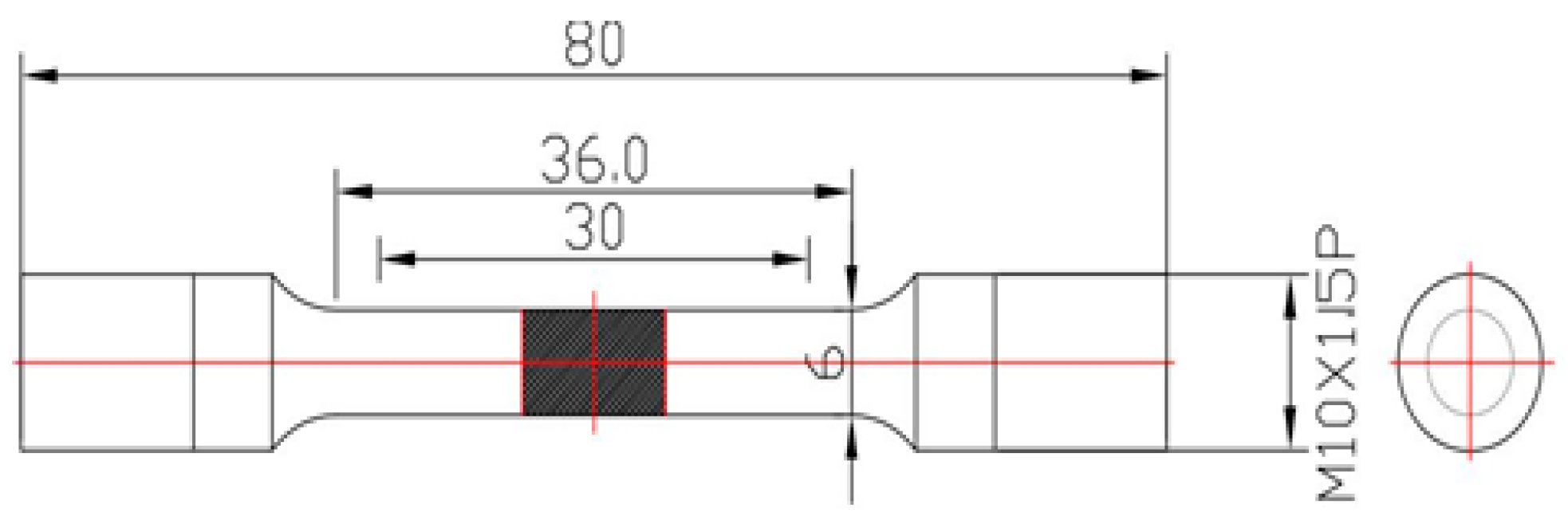
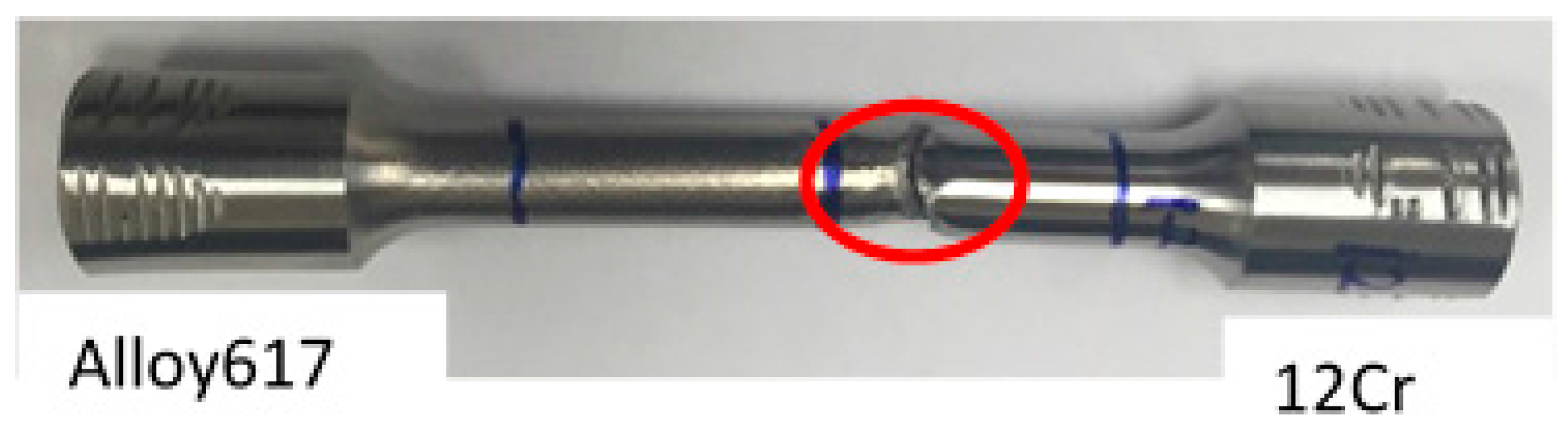
4.1. Specimen and Test Procedure

Tensile and fatigue test specimens of the dissimilar material welded joint between Alloy 617 and 12Cr steel alloy were fabricated from seven-pass welded plate in accordance with ASTM-E8 standard [28]. Figure 9 shows test specimen configuration. Gauge length of the specimen included base metals (Alloy 617 and 12Cr steel), their HAZ, and weld metal. Tensile and fatigue strengths of dissimilar material welded joint were evaluated by using a material testing system (INSTRON 8801, LLC, Seoul Korea, 100 kN). Loading speed for tensile test was controlled by displacement of 1 mm/min. Fatigue tests were started from σmax = 690 MPa, corresponding to 90% of the static tensile strength (767 MPa) of a multi-pass dissimilar material weld between Alloy 617 and 12Cr steel. Tests were performed using a 10% load decreasing method until 106 cycles as illustrated in Table 4. The fatigue load frequency was 10 Hz in sine wave. Load ratio (R = Pmin/Pmax) was 0.1. The load range was constant.

4.2. Calculation of Stress Range Considering Welding Residual Stresses

For the appraisal of stress range, a technique was published by Bae et al. that incorporated welding residual stresses [17]. They used modified Goodman equation to calculate stress range by taking welding residual stresses into account. Maximum stress (σmax) values were taken from Table 4. Minimum stress (σmin) was calculated using Equation (6):
R = σ min σ max
Equation (7) represents the Goodman equation used to measure the stress range without considering welding residual stresses
σ a S e + σ mean S u = 1
where
σ a ( stress   amplitude ) = σ max σ min 2 ;
and
σ mean ( mean   stress ) = σ max + σ min 2
  • Se: fatigue strength
  • Su: ultimate strength
The proposed modified Goodman equation taking into account the welding residual stresses can be represented as Equation (8):
σ a r S e + ( σ mean + σ r ) S u = 1
where σa-r is the stress taking into account the welding residual stresses. It can be calculated by using Equation (9):
σ a r = S e { 1 ( σ mean + σ r ) S u }

4.3. Results and Discussion

Figure 10 shows the relationship between the stress (σ) and the fatigue life (Nf) of a dissimilar material multi-pass welded joint between alloy 617 and 12Cr steel. Fatigue tested specimens mostly failed at HAZ of 12Cr steel alloy as shown in Figure 11, even though welding residual stresses were reduced during machining for specimen fabrication. This might be due to higher welding residual stress distribution as compared to those of alloy 617, and the metallurgical microstructure and composition changes during multi-pass welding heat cycle [18].
From Figure 10, the low fatigue limit that was the stress value did not fail until 106 cycles of a dissimilar material multi-pass welded joint between Alloy 617 and 12Cr steel alloy, σL, were assessed to be around 306.8 MPa. This was 40% of the static tensile strength (767 MPa) of the dissimilar material. Since welding residual stresses commonly become crack driving factors in the welded structure, it is very important to take into account welding residual stresses for safe design of welded structures. However, as mentioned above, since welding residual stresses were relieved during fabrication of fatigue specimen, it is difficult to assess the effect of welding residual stress on fatigue strength from Figure 12. In this study, stress range including welding residual stresses was calculated by modified Goodman equation represented by Equation (9). Figure 12 shows comparison of stress ranges including and not including the welding residual stress. Stress ranges (σa) that do not include the welding residual stresses are 14% higher than those that include the effect of welding residual stresses. The low stress range limit not including the residual stresses was 276.1 MPa. The low stress range limit including the welding residual stress was predicted to be 206.9 MPa. This means that welding residual stresses should be taken into account for fatigue design of the welded structure.

5. Conclusions

In this study, we investigated residual stresses of multi-pass dissimilar material welded joint both experimentally and by numerical simulation. Fatigue life assessment of the dissimilar material welded joint was also carried out. Our conclusions are summarized in the following:
(1)
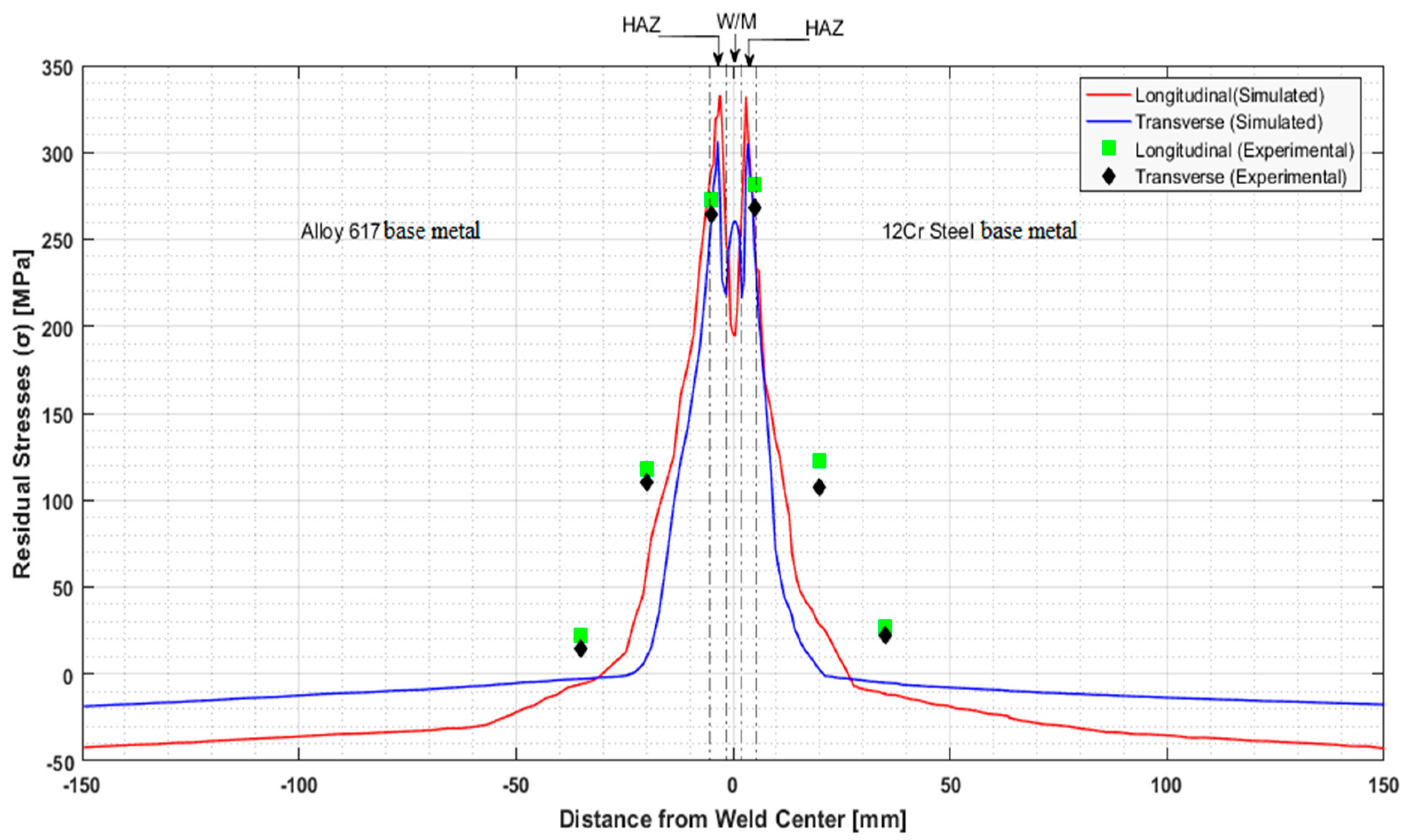
Welding residual stresses at the weld of dissimilar welded joint distributed complicatedly on longitudinal and transverse directions. Results of numerical and experimental analysis showed a good agreement qualitatively.
(2)
Numerical and experimental peak values of welding residual stresses at HAZ of the weld on the 12Cr steel side were predicted to be 333 and 282 MPa HAZ, respectively.
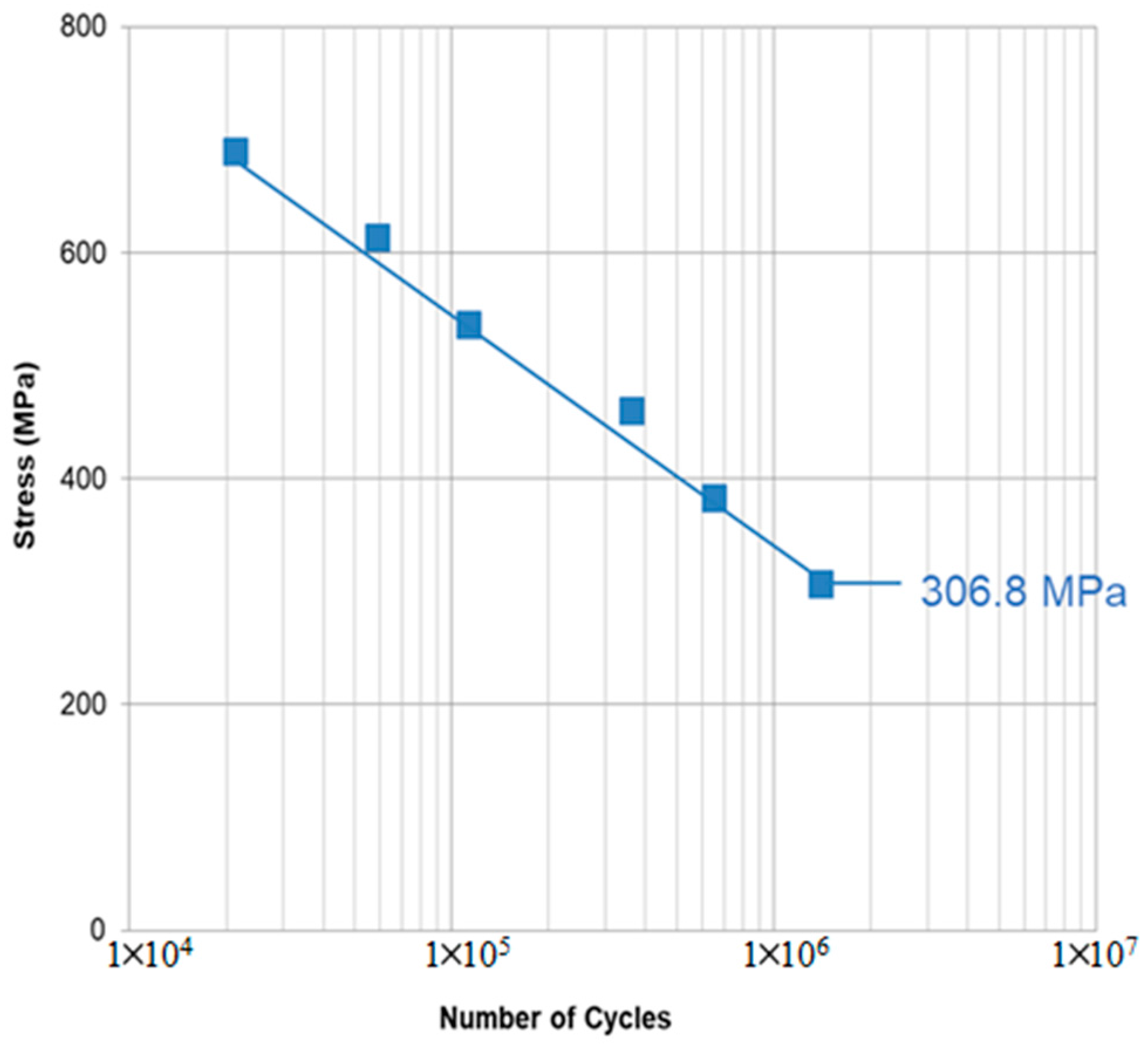
(3)
The low fatigue limit of dissimilar material welded joint was assessed to be 306.8 MPa, which was 40% of tensile strength (767 MPa).
(4)
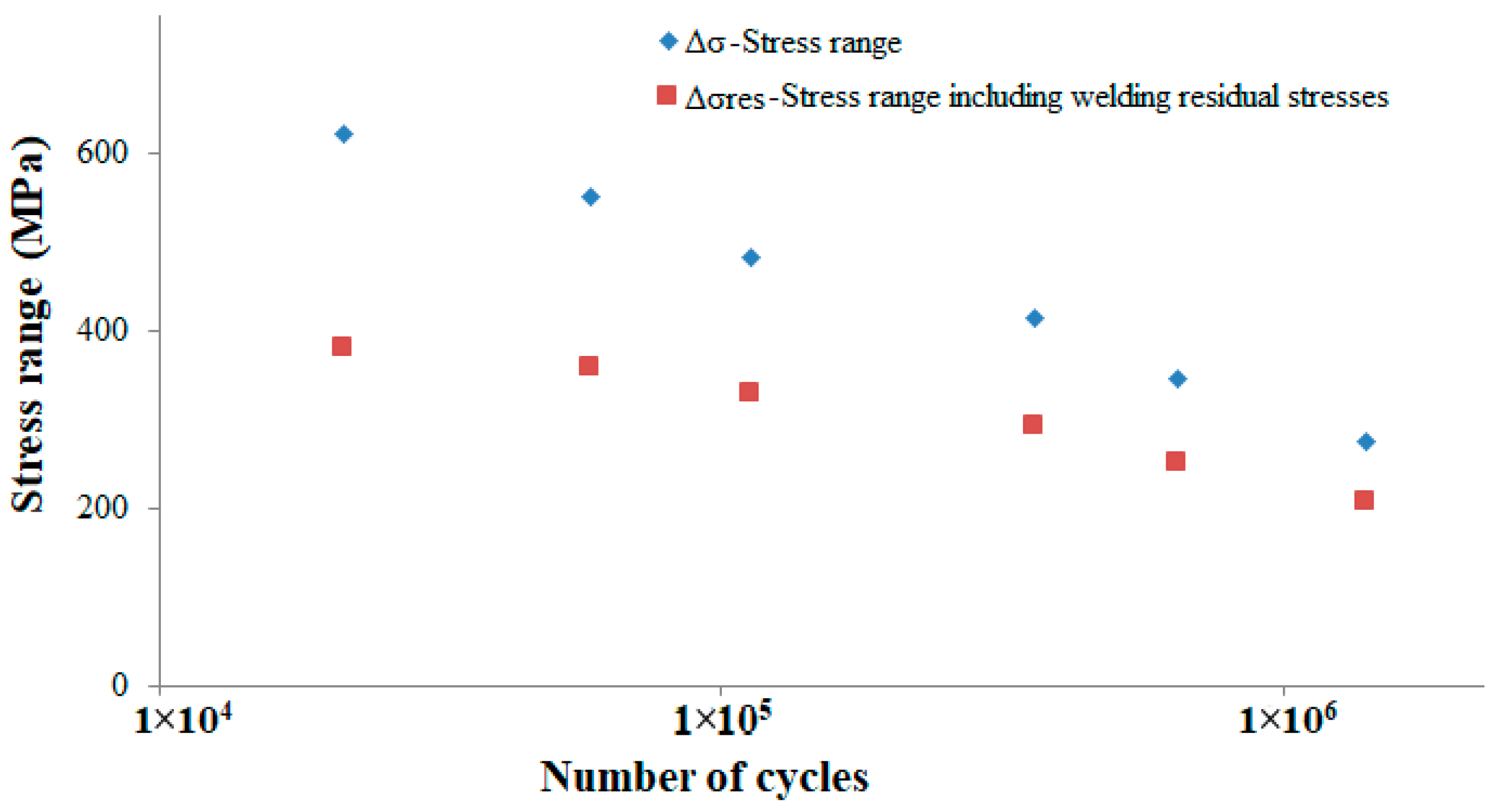
Stress range values without including welding residual stresses were 14% higher than those calculated by including the effect of residual stresses.

Acknowledgments

This work was supported by the Reliability Evaluation Lab of the Mechanical Engineering Department, Sungkyunkwan University, Suwon, Korea.

Author Contributions

H.W.A. conceived and designed the experiments; H.W.A. and J.H.H. performed the experiments and analyzed the data under the supervision of D.H.B. All experiments were performed in Sungkyunkwan University, Korea; H.W.A. wrote the paper.

Conflicts of Interest

The authors have no conflict of interest to disclose.

References

  1. Xiang, W.; Chen, Y. Performance improvement of combined cycle power plant based on the optimization of the bottom cycle and heat recuperation. J. Therm. Sci. 2007, 16, 84–89. [Google Scholar] [CrossRef]
  2. Franco, A.; Casarosa, C. On some perspectives for increasing the efficiency of combined cycle power plants. Appl. Therm. Eng. 2002, 22, 1501–1518. [Google Scholar] [CrossRef]
  3. Abe, F. Research and Development of Heat-Resistant Materials for Advanced USC Power Plants with Steam Temperatures of 700 °C and Above. Engineering 2015, 1, 211–224. [Google Scholar] [CrossRef]
  4. Ennis, P.J.; Strang, A.; Gill, S.P.; McColvin, G.M.; Atkinson, H.V. Microstructural stability of nickel based alloys for advanced power plant applications. Energy Mater. 2009, 4, 184–188. [Google Scholar] [CrossRef]
  5. Greenfield, P.; Marriott, J.; Pithan, K. A Review of the Properties of 9–12% Chromium Steels for Use as HP/IP Rotors in Advanced Steam Turbines; Commission of the European Communities: Whetstone Leicester, UK, 1989. [Google Scholar]
  6. Martinsen, K.; Hu, S.J.; Carlson, B.E. Joining of dissimilar materials. CIRP Ann. Manuf. Technol. 2015, 64, 679–699. [Google Scholar] [CrossRef]
  7. Deogade, S.R.; Ambade, P.S.P.; Patil, A. Finite Element Analysis of Residual Stresses on Ferritic Stainless Steel using Shield Metal Arc Welding. Int. J. Eng. Res. Gen. Sci. 2015, 3, 1131–1137. [Google Scholar]
  8. Lohe, D.; Vohringer, O. Handbook of Residual Stress and Deformation of Steel; ASM International: Geauga County, OH, USA, 2002; pp. 54–69. [Google Scholar]
  9. Jenney, C.L.; O’Brien, A. Welding Handbook; American Welding Society: Miami, FL, USA, 1991; Volume 1, p. 982. [Google Scholar] [CrossRef]
  10. Kandil, F.A.; Lord, J.D.; Fry, A.T.; Grant, P.V. A Review of Residual Stress Measurement Methods—A Guide to Technique Selection; National Physical Laboratory Material Centre: Middlesex, UK, 2001. [Google Scholar]
  11. Galietti, U.; Palumbo, D. Thermoelastic stress analysis of titanium components and simultaneous assessment of residual stress. In Proceedings of the 14th International Conference on Experimental Mechanics, Poitiers, France, 4–9 July 2010; EPJ Web of Conference. Volume 6, p. 38015. [Google Scholar] [CrossRef]
  12. Du, Y.; Backman, D.; Patterson, E. A new approach to measuring surface residual stress using thermoelasticity. In Proceedings of the Society for Experimental Mechanics—11th International Congress and Exhibition on Experimental and Applied Mechanics, Orlando, FL, USA, 2–5 June 2008; pp. 673–680. [Google Scholar]
  13. Zang, W.; Gunnars, J.; Dong, P.; Hong, J.K. Improvement and Validation of Weld Residual Stress Modelling Procedure; Report Number 2009:15; Swedish Radiation Safety Authority: Stockholm, Sweden, 2009; Volume 15.
  14. Syngellakis, A.; Wu, S. Finite element predictions of residual stresses due to heat transfer during welding. In WIT Transactions on Engineering Sciences; WIT Press: Ashurst, UK, 2012; Volume 75, pp. 333–344. ISBN 9781845646028. [Google Scholar]
  15. Zeitschrift, A.; Band, I.K.; Link, P.; Dienst, E. Fatigue Strength and Safety of Welded Structures (Bridges, Structural Steel Work and Pressure Pipes); ETH-Bibliothek: Zurich, Switzerland, 1936. [Google Scholar] [CrossRef]
  16. Al Hajri, M.; Malik, A.U.; Meroufel, A.; Al-Muaili, F. Premature failure of dissimilar metal weld joint at intermediate temperature superheater tube. Case Stud. Eng. Fail. Anal. 2015, 3, 96–103. [Google Scholar] [CrossRef]
  17. Bae, D.H.; Sohn, I.S.; Hong, J.K. Assessing Effects of Residual Stress on the Fatigue Strength of Spot Welds. Weld. J. 2003, 82, 18–23. [Google Scholar]
  18. Ahmad, H.; Hwang, J.; Lee, J.; Bae, D. An Assessment of the Mechanical Properties and Microstructural Analysis of Dissimilar Material Welded Joint between Alloy 617 and 12Cr Steel. Metals 2016, 6, 242. [Google Scholar] [CrossRef]
  19. Corlett, B.J.; Lucas, J.; Smith, J.S. Sensors for narrow-gap welding. IEE Proc. A Sci. Meas. Technol. 1991, 138, 213–222. [Google Scholar] [CrossRef]
  20. Shim, Y.; Feng, Z.; Lee, S.; Kim, D.; Jaeger, J.; Papritan, J.C.; Tsai, C. Determination of Residual Stresses in. Weld. J. 1992, 71, 305–312. [Google Scholar]
  21. Zain-Ul-Abdein, M.; Nélias, D.; Jullien, J.F.; Deloison, D. Thermo-mechanical analysis of laser beam welding of thin plate with complex boundary conditions. Int. J. Mater. Form. 2008, 1, 1063–1066. [Google Scholar] [CrossRef]
  22. Inconel Alloy 617. Available online: http://www.specialmetals.com/assets/smc/documents/alloys/inconel/inconel-alloy-617.pdf (accessed on 29 October 2017).
  23. Coussement, C.; Dhooge, A.; de Witte, M.; Dobbelaere, R.; van der Donckt, E. High temperature properties of improved 9% Cr steel weldments. Int. J. Press. Vessel. Pip. 1991, 45, 163–178. [Google Scholar] [CrossRef]
  24. Hong, J.K.; Tsai, C.L.; Dong, P. Assessment of Numerical Procedures For Residual Stress Analysis of Multipass Welds. Weld. J. N. Y. 1998, 77, 372–382. [Google Scholar]
  25. Bae, D.H.; Kim, C.H.; Cho, S.Y. Numerical Analysis of Welding Residual Stress Using Heat Source Models for the Multi-Pass Weldment. J. Mech. Sci. Technol. 2002, 16, 1054–1064. [Google Scholar] [CrossRef]
  26. Bae, D.H.; Tsai, C.L. Effects of Heat Source Models in Numerical Analysis for Transient Thermal History and Residual Stresses; The Korean Society of Mechanical Engineers (KSME): Seoul, Korea, 1999; pp. 309–315. [Google Scholar]
  27. ASTM E837-13a Standard Test Method for Determining Residual Stresses by the Hole-Drilling Strain-Gage Method. Available online: https://www.astm.org/Standards/E837.htm (accessed on 31 August 2017).
  28. ASTM International. Standard Test Methods for Tension Testing of Metallic Materials 1; ASTM International: West Conshohocken, PA, USA, 2009; Volume I, pp. 1–27. [Google Scholar] [CrossRef]
Figure 1. Specimen with U-groove (Unit: mm).
Metals 08 00021 g001
Figure 2. Finite element mesh of 3-D model.
Metals 08 00021 g002
Figure 3. Numerical analysis procedure for the uncoupled thermo-mechanical analysis [21].
Metals 08 00021 g003
Figure 4. Physical and mechanical properties of Alloy 617.
Metals 08 00021 g004
Figure 5. Physical and mechanical properties of 12Cr steel.
Metals 08 00021 g005
Figure 6. Heat input model with ramp function.
Metals 08 00021 g006
Figure 7. (a) RS-200 milling guide, (b) position of hole drilling.
Metals 08 00021 g007
Figure 8. Comparison of FE analysis results with experimental measurements.
Metals 08 00021 g008
Figure 9. Configuration of test specimen (ASTM E8M, unit: mm).
Metals 08 00021 g009
Figure 10. S-N curve for fatigue test result.
Metals 08 00021 g010
Figure 11. The fatigue tested specimen (failed at HAZ of 12Cr steel alloy).
Metals 08 00021 g011
Figure 12. Comparison of Δσ-Nf relations.
Metals 08 00021 g012
Table 1. Mechanical properties of alloy 617, 12Cr steel, and dissimilar material weld.
Base MaterialYield Strenght (MPa)Tensile Strenght (MPA)ElongationReduction in Area (%)Melting Point (°C)
Alloy 61732273262561330
12Cr55175818501375
Dissimilar material welded joint49076748--
Table 2. Chemical composition of alloy 617, Thyssen 617, and 12Cr steel.
Base/Filler MetalChemical Composition (Weight %)
NiCrCoMoAlCFeSiTiCuMnS
Alloy 61744.32212.59.01.20.071.50.50.30.20.50.008
12Cr0.4311.6-0.04-0.13Bal.0.4-0.10.58-
Thyssen 61745.721.511.09.01.00.051.00.11---
Table 3. Optimum welding conditions.
PassShield GasVoltage (V)Current (A)Welding Speed (cm/min)Heat Input (kJ/mm)
1Argon-2.5% H210150100.9
2Argon-2.5% H213150101.17
3Argon-2.5% H216150101.44
4Argon-2.5% H216150101.44
5Argon-2.5% H216150101.44
6Argon-2.5% H216150101.44
7Argon-2.5% H216150101.44
Table 4. Fatigue test conditions.
Load Conditions
σmax (MPa)0.9σu = 690.30.8σu = 613.60.7σu = 536.90.6σu = 460.20.5σu = 383.50.4σu = 306.8
Stress RatioR = 0.1
FrEquation10 Hz

