Discrete Optimization of Internal Part Structure via SLM Unit Structure-Performance Database

College of Mechatronics and Automation, National University of Defense Technology, Changsha 410073, China
*
Author to whom correspondence should be addressed.
Metals 2018, 8(1), 45; https://doi.org/10.3390/met8010045
Submission received: 15 November 2017
/
Revised: 4 January 2018
/
Accepted: 5 January 2018
/
Published: 11 January 2018
Abstract
:The structural optimization of the internal structure of parts based on three-dimensional (3D) printing has been recognized as being important in the field of mechanical design. The purpose of this paper is to present a creation of a unit structure-performance database based on the selective laser melting (SLM), which contains various structural units with different functions and records their structure and performance characteristics so that we can optimize the internal structure of parts directly, according to the database. The method of creating the unit structure-performance database was introduced in this paper and several structural units of the unit structure-performance database were introduced. The bow structure unit was used to show how to create the structure-performance database of the unit as an example. Some samples of the bow structure unit were designed and manufactured by SLM. These samples were tested in the WDW-100 compression testing machine to obtain their performance characteristics. After this, the paper collected all data regarding unit structure parameters, weight, performance characteristics, and other data; and, established a complete set of data from the bow structure unit for the unit structure-performance database. Furthermore, an aircraft part was reconstructed conveniently to be more lightweight according to the unit structure-performance database. Its weight was reduced by 36.8% when compared with the original structure, while the strength far exceeded the requirements.
1. Introduction
With the development of science and technology, there is an increasing demand for lightweight and functional parts in the aerospace, automotive, medical industries and other fields. At the same time, shorter machining times and good mechanical properties of the parts are becoming increasingly important. However, the functional parts often have a complex structure made of various parts, which is difficult to manufacture using traditional processing technology. Furthermore, there are often redundant materials in conventional parts due to the inherent restrictions of the conventional manufacturing processes, which make it difficult to create lightweight versions of parts.
Selective laser melting (SLM) is one of the new additive manufacturing (AM) techniques that emerged in the late 1980s and 1990s [1], which can directly make complex three-dimensional metal parts, according to Computer Aided Design (CAD) data, by selectively melting successive layers of metal powders [2]. The principle of SLM technology is as follows. Firstly, the three-dimensional (3D) model of the part is divided into slices by the computer. After this, each slice of the part is manufactured in the order from the bottom to the top, and finally, the full 3D solid is formed by the accumulation of the slices [3]. SLM completely melts the powder material, which enables a density of approximately 100% and can maintain mechanical properties that match or even beat those of conventionally manufactured parts (cutting and casting) [4]. However, residual stress is a serious issue in SLM [5]. As a result, researchers have worked to develop solutions to this problem, such as process modeling and simulation [6], process control and post-processing methods [7,8], design and analysis of overhanging structures [9], and so on. However, the current research does not provide a standard solution as different cases have different solutions. When designing parts based on SLM technology, it is necessary to improve the problem of residual stress, according to the design objective and the technological characteristics of SLM.
The machinability of the SLM is weakly related to the complexity of the structure for each part, which forms a good complement to conventional manufacturing processes [10,11]. The powerful free-formability offered by SLM shows great potential in making advanced lightweight and functional structures, which are highly desired by engineering sectors. Furthermore, there have been many new design methods for lightweight and functional parts, according to its processing characteristics.
The current main design method to obtain lightweight and functional structures by SLM involves designing the structural functional units and optimizing the internal structure of parts. Furthermore, many related studies have achieved very good results, which are shown as follows.
Harrysson et al. [12] proposed a hybrid approach that combines analytical modeling, with experimentation and simulation performed for the design of 3D cellular structures. A re-entrant auxetic cellular structure was modeled by this approach and tested. The results showed good consistency of the theories with the experiments when structural symmetry is maximized. Kumar et al. [13] studied the effects of the foam structures with different pore units and porosity on the performance of the scaffolds used in human tissue regeneration. The mechanical properties were tested. Finally, they concluded that the use of gradient porosity can ensure high tensile and compression properties as well as increase impact absorption capacity under the premise of a lighter weight of the scaffolding structure. Pinto et al. [14] studied the difference in performance between a single-sized and a double-sized lightweight aluminum foam structure. This involves processing these two non-metallic structure prototypes by 3D printing, before processing the final metal structure by investment casting. Compression tests that were performed on the two structures have shown that the compression strength of the double-sized aluminum foam structure increased by 83%, the stiffness increased by 29%, and the energy absorption capacity increased by more than 27% when compared to the single-size aluminum foam structure. Feih et al. [15] compared the compression performance, energy absorption capacity of the Kagome structure, and the other three atomic lattice structures (body-centered cubic, face-centered cubic, and combination of body-centered cubic and face-centered cubic) by the shear test, compression test, and so on. It was shown that the Kagome structure was superior to other traditional lattice structures and had the same energy absorption capacity as the aluminum and titanium alloy honeycomb structures. Moon et al. [16] compared the performance of the 3D Kagome lattice structure, the 3D pyramid lattice structure and the hexagonal diamond lattice structure based on the strong adaptability, low energy consumption, light weight, and high flexibility requirements of Unmanned Aerial Vehicle (UAV). It was found that the 3D Kagome lattice structure had the strongest bearing capacity, while the hexagonal diamond structure had the highest energy absorption energy. Finally, the UAV wing was designed with the Kagome lattice structure and fabricated by 3D printing.
The results show that the lightweight parts designed by this method can satisfy the requirements for use. The research on structural functional units has achieved some results, but there is a lack of data regarding the structure and performance of units. Furthermore, the structural parameters of many units are designed based on a particular application, so it is difficult to generalize these structural units to the whole mechanical design field. This results in the engineers spending a considerable amount of effort to choose the most suitable unit with suitable structural parameters each time that they optimize the internal structure of parts. Therefore, the establishment of a unit structure-performance database, which contains a large number of units, as well as their structure and performance data, is of great significance in the field of mechanical design so that the engineers can directly design the parts.
There is scarce research available with respect to creating such a database, although some progress has been made. In the sphere of bone regeneration, Wettergreen et al. [17] proposed the characterization and documentation of a database of micro-architectures, which can be seamlessly merged according to the mechanical properties (stiffness and strength), flow perfusion characteristics, and porosity, which is chosen by the scientist based on the required application and anatomic location. This was helpful in aiding scientists in the fabrication of a successful scaffold.
This paper investigated a creation of a unit structure-performance database, which contains a wide variety of units that can be fabricated with SLM. Each unit had a sub-database containing all of the structural parameter combinations that meet the manufacturability of SLM and corresponding performance. Several structural functional units of the database were introduced and a design method of the internal structure optimization of parts based on the unit structure-performance database was proposed. The bow structure unit was used to show how to build the unit structure-performance database. All data of the structure and performance characteristics of the bow structure were established through the theoretical calculations and experiments. Based on the unit structure-performance database, the structure of an aircraft sensor mount was optimized to be more conveniently lightweight. The results showed that its weight was reduced by 36.8% when compared with the original structure, while its strength far exceeded the requirements. This verified the feasibility and advantage of the design method.
2. Methods
Constructing the structural unit by absorbing the typical structure from the fields of machinery and architecture is the core method of creating the unit structure-performance database.
2.1. Compression Structural Unit
Some bionic structures show excellent compressive properties and can be easily included in the structural unit. As shown in Table 1, the planar structure unit was designed, according to the biological structure of the diatoms and the dendritic compression unit was designed according to the biological structure of the trees. The planar structure unit has excellent compressive properties, while the dendritic unit is able to achieve a higher utilization rate of the material, while ensuring the compressive strength of the structure.
2.2. Torsional and Bending Structural Unit
The cylindrical and rectangular structure corresponding to bamboo and rhubarb has outstanding torsional and bending properties. Therefore, this was included in the design of the torsional bending unit (Table 2).
2.3. Elastic Unit
The elastic structure of traditional machinery was designed as an elastic unit (Table 3). Different elastic units have different performance characteristics. For example, the dome unit has a higher strength and the dome unit can withstand a greater displacement.
2.4. Other Units
There are many other structures that have excellent performance in some respects (Table 4).
2.5. Example of Bow Structure
The paper demonstrates how to create a unit structure-performance database, which has a complete set of data of the structural units, by taking the bow structure unit as an example. The bow structure unit is a unit in the -unit structure-performance database. Our choice of the bow structure as an example was arbitrary.
2.5.1. Structure Design and Parameter Selection of Bow Structure Unit
According to the structural characteristics of the bow, the primary bow structure unit was established based on the SLM process characteristics, as shown in Figure 1. After this, the paper will discuss the selection of parameters for the bow structure unit, specifically.
In order to facilitate the study of the bow structure unit, the unit was designed in the form of an ellipse. The parameters of the unit are as follows: the bore horizontal axis of a, the bore vertical axis of 2b, the wall thickness of m, and the width of n (Figure 2a). The units are symmetrical along the horizontal axes.
However, the bow structure unit is required to have the same height H when applied and the performance analysis of the unit is generally based on a certain unit height H. A change in m and b will have an impact on the H. Furthermore, we found that the support area at the top of bow structure unit is very small, which does not meet the requirements of 3D printing process. Therefore, the height of the bow structure unit was limited to H = 10 mm, which is also the typical height of the 3D printing unit structure. In order to ensure that H was this value, the bore vertical axis was also defined at 2b = 8 mm. At the same time, the portion of the unit that has a distance of more than H/2 from the horizontal axis of the bore was removed (Figure 2b).
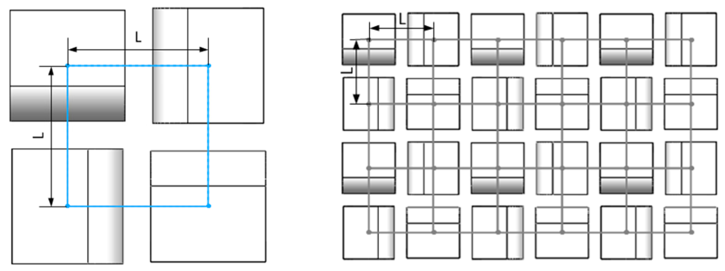
The appropriate layout design is beneficial in improving performance of the unit. When supporting a large plane with a plurality of bow structure unit, it is necessary to ensure the lateral deformation of the unit and maximize the uniform distribution of the unit at the same time. Therefore, in the layout of the bow structure unit, four bow structure units form a small structural body and two adjacent units in each structure body are perpendicular to each other, with the unit center distance being L (Figure 3).
In this case, the units are distributed in the form of a square with side lengths of L. After this, according to the structural and force characteristics of the applied parts, these small structure bodies are arrayed in sequence. To ensure the manufacturability of 3D printing, the edge of less than one unit must be supported by the lattice structure.
The size of L directly affects the performance of the part. A smaller L results in a greater strength and quality of the part. If L is too small, the unit lateral deformation space will be insufficient, and thus, the performance of parts will be affected. Furthermore, on the contrary, the dangling size of the parts will be increased and thus, the manufacturability of the part will be affected. In summary, the impact of changes in the size of L on unit performance has both advantages and disadvantages. Therefore, when creating the unit sub-database, the size of L should be fixed. Different sub-bases should be created when the size of L is changed.
The bow structure unit must be designed to meet the manufacturability requirements of SLM. The main process constraints of SLM technology are the minimum machining size constraint, the dangling size constraint between the largest structures, the minimum inclination angle constraint, and the maximum cantilever size constraint. According to the current commercial SLM equipment process performance, the smallest size of parts that can be manufactured is 0.4 × 0.4 mm. When the part is smaller than this size, the shape of the parts will be distorted and the quality will be too low. The maximum suspended support spacing is 5 mm. However, when the support spacing is more than 3 mm, the suspended part of the part will have different degrees of collapse and deformation, thus affecting the performance of the part. Therefore, the maximum suspended support spacing between the structures is limited to be 3 mm. The minimum inclination angle is 45° as structures with tilt angles less than 45 degrees tend to warp. The maximum cantilever size of the part is 1 mm. When the cantilever size is larger than 1 mm, the cantilever boundary will collapse or warp.
According to the manufacturability requirements of SLM and the layout of bow structure unit, the paper established the structural parameter constraints of the bow structure unit, as shown in Equations (1)–(5). There are several points that are important to note. In order to ensure the lateral deformation space of the unit, we set the minimum gap between adjacent units to be 0.5 mm. Furthermore, we placed a 1 mm chamber at the joint of the unit bow surface and the upper part.
m ≥ 1
L − n ≤ 3
L − 1/2(a + m + n) ≥ 0.5
L + 1/2(a + m) − 1/2n − sqrt(1 − 5^2/(4 + m)^2) × (m + a) ≤ 3
(4 + m)^2/(5(a + m)) × sqrt(1 − 5^2/(4 + m)^2) ≥ π/4
According to Equations (1)–(5) and setting the appropriate parameter intervals, we can calculate the whole discrete parameter combinations that meet the SLM manufacturability requirements for the bow structure unit. We can use this to manufacture all of the units with the discrete parameter combinations by SLM and obtain their performance data through tests. After this, we collected the unit parameters and performance data in order to establish the structure-performance database of the bow structure unit. Smaller intervals allow for a more detailed database.
2.5.2. Material Test of Bow Structure Units
The paper selected the partial units that meet the SLM manufacturability requirements with L being 7 mm and created their structure-performance database as an example. Table 5 shows the structural parameters of the selected bow structure units.
The bow structure unit samples were made from a Ti6Al4V titanium alloy powder with an average particle size of 30 ± 15 μm. The powder consisted of Al (5.5–6.75%), V (3.5–4.5%), Fe (0.3% max), N (0.05% max), O (0.2% max), C (0.08% max), and H (0.015% max). The Scanning Electron Microscope (SEM) (COXEM, Co., Ltd., Daejeon, Korea) micro-graph of the Ti6Al4V powder is shown in Figure 4. It had good mechanical characteristics with a tensile strength of greater than 1100 MPa and a yield strength of 1000 ± 100 MPa.
These units were first designed in Solidworks (2014, Dassault Systèmes SOLIDWORKS Corp, Concord, MA, USA), before being exported in the STL format for slicing and 3D printing. Each unit has three samples for balancing the machining and test errors. All of the samples for this study were manufactured by the FS271M system (Farsoon High-Technology Co., Ltd., Changsha, China), which utilized a 225 W ytterbium fiber laser. This machine has an effective building volume of 275 mm × 275 mm × 320 mm. The 100 μm diameter laser beam was scanned at 1000 mm/s in an argon gas environment surrounding the building parts. The oxygen level in the process chamber was maintained at below 0.1%. The building platform was preheated to 120 °C and maintained at that temperature. The layer thickness was 30 µm with a spot diameter of 136 µm. After being manufactured, all of the samples underwent heat treatment for 2 h at 850 °C (followed by furnace cooling) to improve performance. The processed samples are shown in Figure 5.
In this paper, the unit performance was obtained by compression test (Figure 6), which included Young’s modulus, yield strength, energy absorption capacity, and so on. The equipment used in this test was the WDW-100 Compression Tester (Changchun Testing Machine Co., Ltd., Changchun, China). The maximum load range was ±100 kN, the load measurement accuracy was ±0.5%, the loading speed was 0.5 mm/min, and the samples were assumed to be straight during the test. The whole test was carried out at room temperature.
2.5.3. Establishing Structure-Performance Database of Bow Structure Units
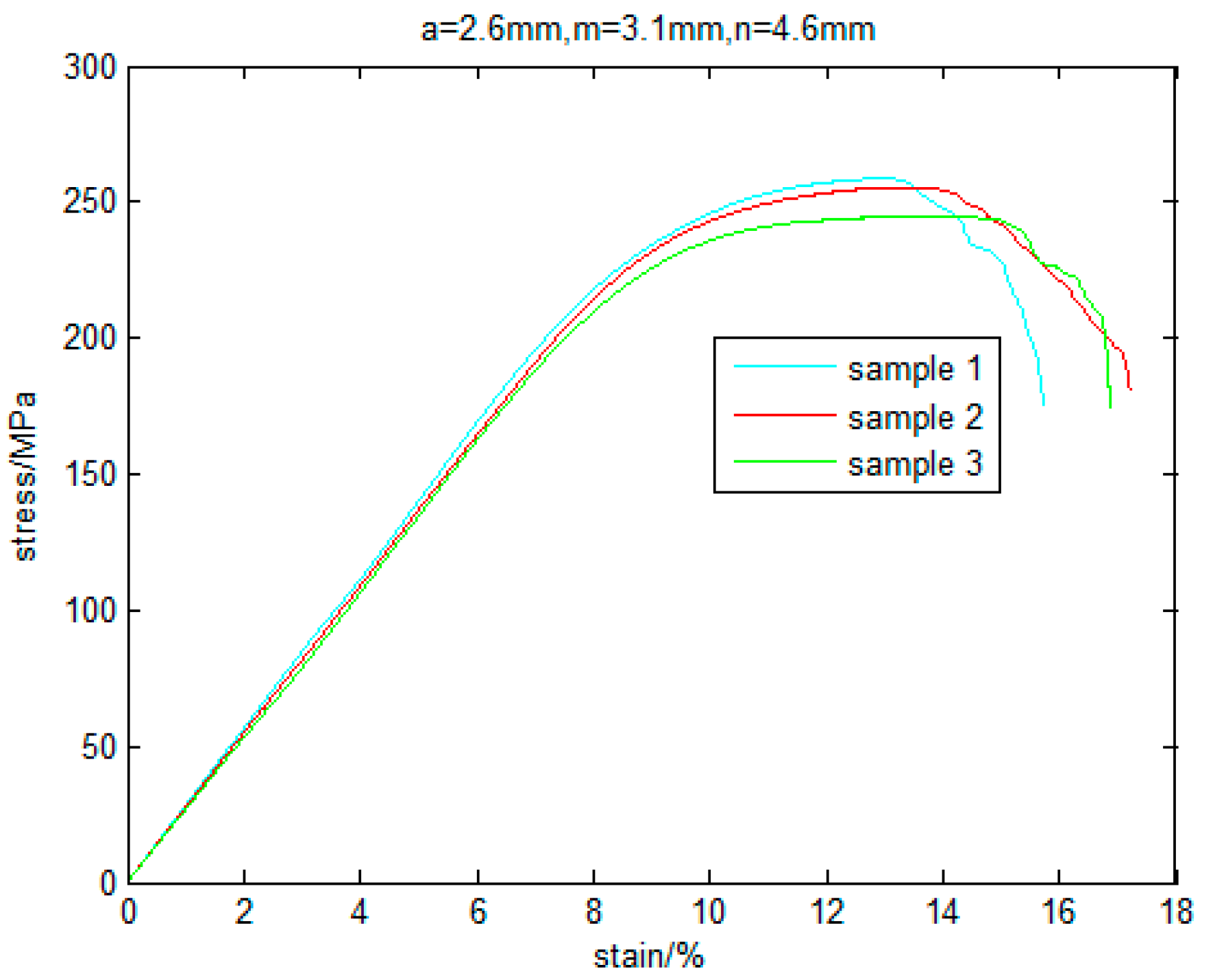
Figure 7 shows the stress-strain curve of the three samples of the bow structure unit with a of 2.6 mm, m of 3.1 mm, and n of 4.6 mm, where the slope of the curve is the Young’s modulus of the unit. The stress at 0.2% plastic deformation of the unit is the yield stress, while the displacement at this timepoint is the yield displacement. The area covered by the curve and the X-axis is the energy absorbed by the unit.
These curves are very consistent, especially in the elastic deformation stage. The differences between the three curves area acceptable, especially when considering that many factors can lead to these differences, such as testing errors, manufacturing errors, and so on. In summary, the process for the part tested was of excellent quality.
The stress-strain curves of each unit are processed to obtain their performance data and their structure-performance database is shown in Table 6.
From Table 6, the bow structure unit has excellent strength and energy absorption, which can be used to enhance the impact resistance of the parts and allow for the manufacturing of parts with lighter weights.
Table 6 show the structure-performance database of some units. When redesigning a structure, selecting the appropriate unit directly from the database is useful. However, the establishment of the database requires intensive work as it needs a considerable amount of experimentation using units with different structural parameters and different layout parameters. Table 6 is just an example of how to set up the structure–performance database, which is a very small part of the database.
3. Application of Unit Structure-Performance Database
Many parts can be optimized conveniently based on the unit structure-performance database, especially the aeronautics parts, such as the sensor mount, the blisk and its blades [18], and so on. In this paper, the structure of a sensor mount of an aircraft was optimized, according to the structure-performance database. The sensor mount on an aircraft is shown in Figure 8a. The optimization goal is to obtain the lightest part with the same strength.
First of all, we analyzed the stress distribution of the part when it is carried by simulation. The sensor mounts model was imported into the ANSYS Workbench (14.5, ANSYS, Inc., Canonsburg, PA, USA) to analyze the maximum stress and deformation of the structure. To simulate the force situation during the launch of the satellite structure, one side of the sensor mount was fixed, while the load was 10 times the gravitational acceleration (Figure 8b).
As shown in Figure 9, the maximum stress of the sensor holder is 9.5 × 10³ Pa, with the stress increasing from the upper surface to the lower surface.
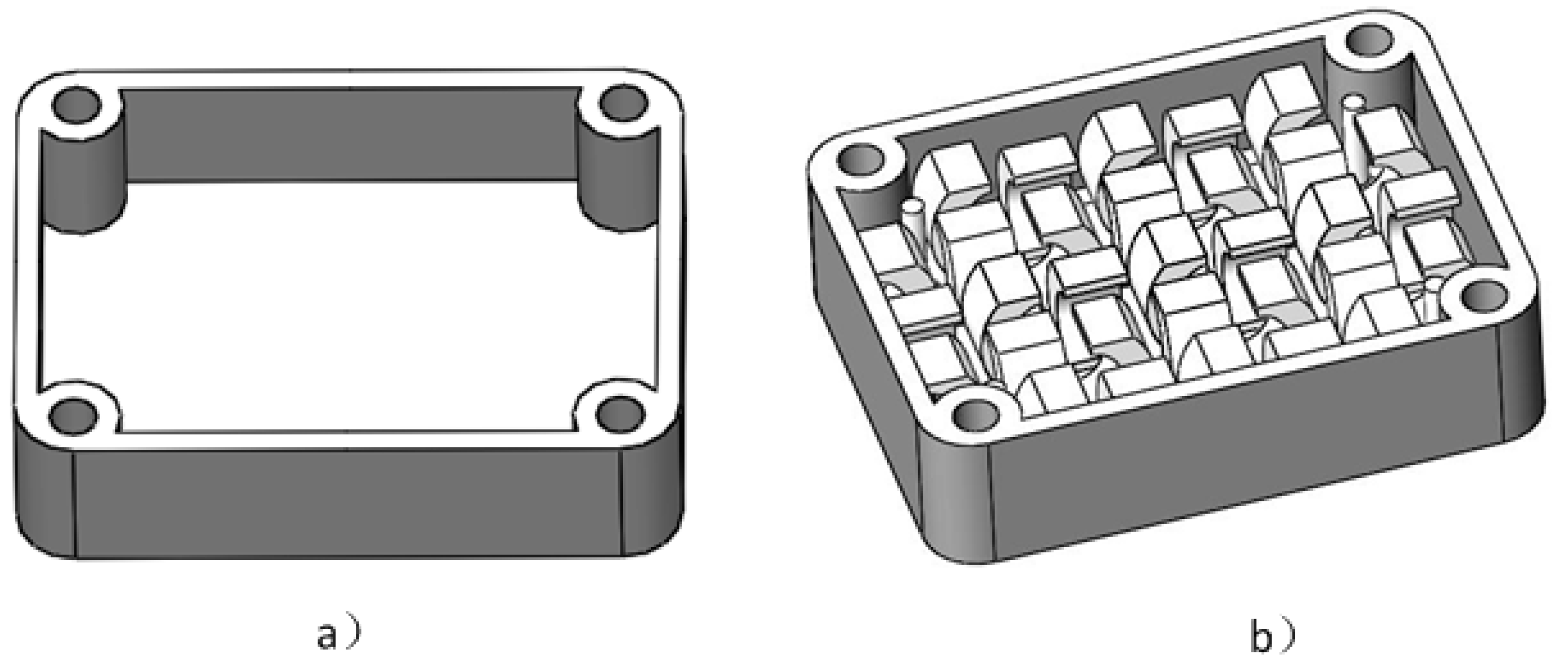
We created the shell of the model in the Solidworks software. According to a previous study [19], when the thickness of the skin is 2 mm, the structure can achieve higher strength and rigidity, while the weight reduces. Therefore, the thickness of the shell was set at 2 mm and the sensor mount after the shell operation is shown in Figure 10a.
Following this, we decomposed the model. According to the stress distribution and shape characteristics, the model was divided into two parts: the mounting hole at four corners and the planar structure. Thin-walled structures and auxiliary structures, such as bolt holes, screw holes, keyways, and auxiliary positioning structures, were not suitable for internal structural reconstruction. Therefore, mainly the middle plane structure was redesigned.
Based on the structure-performance database, a suitable manufacturable unit was selected for filling the gaps, according to the characteristics of each decomposed structure. As the main loading is pressure, the planar structure was considered to fill bow structure units.
The maximum stress of the sensor holder is 9.5 × 10³ Pa, so every unit in Table 6 meets its strength requirements. According to the optimization goal, the paper chose the bow structure with a of 2.6 mm, m of 2.7 mm, and n of 4.6 mm to reconstruct the structure for the lightest part. The reconstructed model of the sensor mounting is shown in Figure 10b.
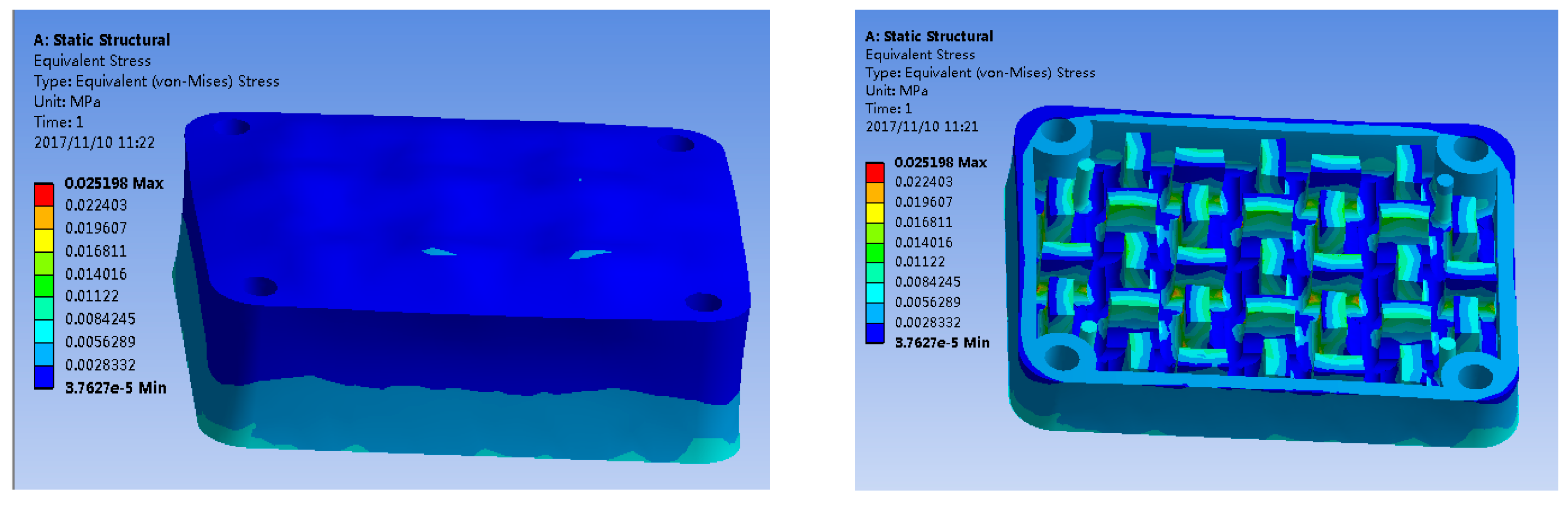
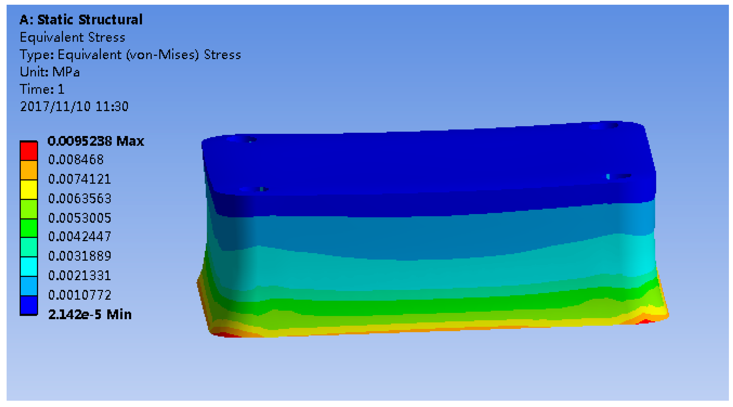
Finally, this paper verified the strength of reconstructed bearings through simulation. As shown in Figure 11, the maximum stress occurs at the junction of the unit and the supporting lower plate. This maximum stress is 2.5 × 10⁴ Pa, which is far less than the average yield strength of the TC4 1000 MPa.
At this time, according to the volume of the three-dimensional model, the weight of the reconstructed model was reduced by 36.8%.
4. Discussion
The printing effect of the samples is good, and there is no obvious processing defects. When printing, a lot of powder adhered to the samples, then some of the powder fell off due to collision and other reasons, so the samples seems very rough.
The highly anisotropic nature of the materials will affect the structural strength and durability of the parts. According to experience, the strength along the print direction is superior to the other directions, so, in general, the print direction is same to the bearing direction.
Appropriate processing parameters of SLM machine can decrease the defects and guarantee the strength and durability of the parts, and the company we chose to manufacture the samples has found excellent process parameters through a large number of tests. In order to control the printing effect, we guarantee the processing parameters and the processing environment strictly during the processing, and using the same post-processing methods.
The paper assumed that the samples were straight during the test, but they were a little offset actually, which is a little different to the actual situation. Therefore, the performance data of the bow structure unit in the structure–performance database obtained through the test has a bit errors when compared with the actual application. However, it is unavoidable when studying the performance of individual unit. When bearing, the units in the optimized parts will also appear different degrees of offset. To get more accurate results, further work should be done to find the corresponding relationship between the individual unit and the grouped units in actual application.
According to the test and analysis, the bow structure unit can absorb some energy when they are elastically deformed and destroyed. So, when the parts after optimization are impacted, part of the energy is absorbed by the unit through deformation and destruction, which reducing the energy transferred to the seat plate, just like a spring. Therefore, the bow structure units can improve the impact resistance of parts.
5. Conclusions
In this paper, a method to optimize the internal structure of a part based on the unit structure-performance database is presented, while several types of units in the unit structure-performance database are introduced. According to the database, engineers can optimize the part by the direct selection of the most appropriate unit and its structural parameters from the database. This will remove the necessity of a large number of experiments and theoretical calculations, thus greatly improving the efficiency.
The bow structure unit is used to illustrate the method of building the structural unit database. Furthermore, the database of the bow structure unit was established, which included all of the data regarding the structural characteristics of the bow structure unit and their corresponding weight, yield stress, energy absorption capacity, and so on.
Compression samples were manufactured by the SLM process and the compression tests were performed to study the characteristics of the bow structure units with different structural parameters. The results showed that the bow structure unit had excellent strength and energy absorption. It equivalent yield stress is 214.1 and it can absorb energy up to 4.2 J with a of 2.4 mm, m of 3.1 mm and n of 4.6 mm. This means that the bow structure unit can be used to enhance the impact resistance of the parts and allow for lightweight parts to be created.
In this paper, the structure of the sensor mount on an aircraft was optimized based on the unit structure-performance database. The designing process was more convenient and quicker. The maximum stress of the sensor mount was 2.5 × 10⁴ Pa, which was far smaller than the average yield strength of the TC4 860 MPa. Meanwhile, its weight was reduced by 36.8% when compared with the original structure.
Acknowledgments
The authors would like to thank Feiyue Zi for the preparation of the bow structure unit samples, and thank Farsoon High-Technology Company for the fabrication of the samples and the provision of the composition of material.
Author Contributions
Zhixiong Zhang proposed the main method of the paper and planned the entire research ideas; Li Tang designed the unit structure in the paper; Li Tang and Qingbiao Zhang conceived and designed the experiments; Qingbiao Zhang performed the experiments; Li Tang, Qingbiao Zhang, Zhixiong Zhang, Keshan Liang and Xiqing Zhao analyzed the data. Finally, Qingbiao Zhang summarized the entire research and completed the first draft of the paper; Keshan Liang polished the writing, translated the draft and adjusted the draft format, then completed the final manuscript; Xiqing Zhao completed the processing of parts and the drawing of some figures.
Conflicts of Interest
The authors declare no conflicts of interest.
Nomenclature
| a | bore horizontal axis |
| m | wall thickness |
| n | width |
| b | bore vertical axis |
| L | layout parameters |
| H | height |
References
- Kruth, J.P.; Levy, G.N.; Klocke, F.; Childs, T.H.C. Consolidation phenomena in laser and powder-bed based layered manufacturing. CIRP Ann. 2007, 56, 730–759. [Google Scholar] [CrossRef]
- Kruth, J.P.; Froyen, L.; Vaerenbergh, J.V.; Mercelis, P.; Rombouts, M.; Lauwers, B. Selective laser melting of iron-based powder. J. Mater. Process. Technol. 2004, 149, 616–622. [Google Scholar] [CrossRef]
- Verhaeghe, F.; Craeghs, T.; Heulens, J.; Pandelaers, L. A pragmatic model for selective laser melting with evaporation. Acta Mater. 2009, 57, 6006–6012. [Google Scholar] [CrossRef]
- Bremen, S.; Meiners, W.; Diatlov, A. Selective Laser Melting: A manufacturing technology for the future. Laser Tech. J. 2012, 9, 33–38. [Google Scholar] [CrossRef]
- Patterson, A.E.; Messimer, S.L.; Farrington, P.A. Overhanging Features and the SLM/DMLS Residual Stresses Problem: Review and Future Research Need. Technologies 2017, 5, 15. [Google Scholar] [CrossRef]
- Papadakis, L.; Loizou, A.; Risse, J.; Bremen, S.; Schrage, J.A. Computational Reduction Model for AppraisingStructural Effects in Selective Laser Melting Manufacturing. Virtual Phys. Prototyp. 2014, 9, 17–25. [Google Scholar] [CrossRef]
- Vrancken, B.; Thijs, L.; Kruth, J.P.; Van Humbeeck, J. Heat treatment of Ti6Al4V produced by Selective Laser Melting: Microstructure and mechanical properties. J. Alloys Compd. 2012, 541, 177–185. [Google Scholar] [CrossRef]
- Martínez, S.; Lamikiz, A.; Ukar, E.; Calleja, A.; Arrizubieta, J.A.; de Lacalle, L.L. Analysis of the regimes in the scanner-based laser hardening process. Opt. Lasers Eng. 2017, 90, 72–80. [Google Scholar] [CrossRef]
- Calignano, F. Design optimization of supports for overhanging structures in aluminum and titanium alloys by selective laser melting. Mater. Des. 2014, 64, 203–213. [Google Scholar] [CrossRef]
- Parthasarathy, J.; Starly, B.; Raman, S.; Christensen, A. Mechanical evaluation of porous titanium (Ti6Al4V) structures with electron beam melting (EBM). J. Mech. Behav. Biomed. Mater. 2010, 3, 249–259. [Google Scholar] [CrossRef] [PubMed]
- Harrysson, O.L.A.; Cansizoglu, O.; Marcellin-Little, D.J.; Cormier, D.R.; West, H.A. Direct metal fabrication of titanium implants with tailored materials and mechanical properties using electron beam melting technology. Mater. Sci. Eng. C 2008, 28, 366–373. [Google Scholar] [CrossRef]
- Yang, L.; Harrysson, O.; Cormier, D.; West, H.; Gong, H.; Stucker, B. Additive Manufacturing of Metal Cellular Structures: Design and Fabrication. JOM 2015, 67, 608–615. [Google Scholar] [CrossRef]
- Kumar, A.; Nune, K.C.; Murr, L.E.; Misra, R.D. Biocompatibility and mechanical behaviour of three-dimensional scaffolds for biomedical devices: Process–structure–property paradigm. Int. Mater. Rev. 2016, 61, 20–45. [Google Scholar] [CrossRef]
- Pinto, P.; Peixinho, N.; Silva, F.; Soares, D. Compressive properties and energy absorption of aluminum foams with modified cellular geometry. J. Mater. Process. Technol. 2014, 214, 571–577. [Google Scholar] [CrossRef]
- Ullah, I.; Brandt, M.; Feih, S. Failure and energy absorption characteristics of advanced 3D truss core structures. Mater. Des. 2016, 92, 937–948. [Google Scholar] [CrossRef]
- Moon, S.K.; Tan, Y.E.; Hwang, J.; Yoon, Y.J. Application of 3D printing technology for designing light-weight unmanned aerial vehicle wing structures. Int. J. Precis. Eng. Manuf. Green Technol. 2014, 1, 223–228. [Google Scholar] [CrossRef]
- Wettergreen, M.A.; Bucklen, B.S.; Starly, B.; Yuksel, E.; Sun, W.; Liebschner, M.A. Creation of a unit block library of architectures for use in assembled scaffold engineering. Comput. Aided Des. 2005, 37, 1141–1149. [Google Scholar] [CrossRef]
- Calleja, A.; Tabernero, I.; Ealo, J.A.; Campa, F.J.; Lamikiz, A.; de Lacalle, L.N. Feed rate calculation algorithm for the homogeneous material deposition of blisk blades by 5-axis laser cladding. Int. J. Adv. Manuf. Technol. 2014, 74, 1219–1228. [Google Scholar] [CrossRef]
- Tang, L.; Wu, C.; Zhang, Z.; Shang, J.; Yan, C. A Lightweight Structure Redesign Method Based on Selective Laser Melting. Metals 2016, 6, 280. [Google Scholar] [CrossRef]
Figure 1.
The bow structure unit.
Figure 2.
(a) The parameters of bow structure unit. (b) Both ends of the unit are removed.
Figure 3.
The layout of bow structure unit.

Figure 4.
Scanning Electron Microscope (SEM) micro-graph of the Ti6Al4V powder.
Figure 5.
The samples of the bow structure unit.
Figure 6.
The compression testing.
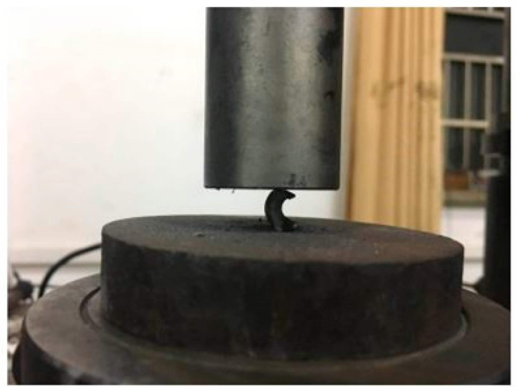
Figure 7.
The stress-strain curve of the bow structure unit.

Figure 8.
(a) The model of the sensor mount. (b) The simulation of the sensor mount.
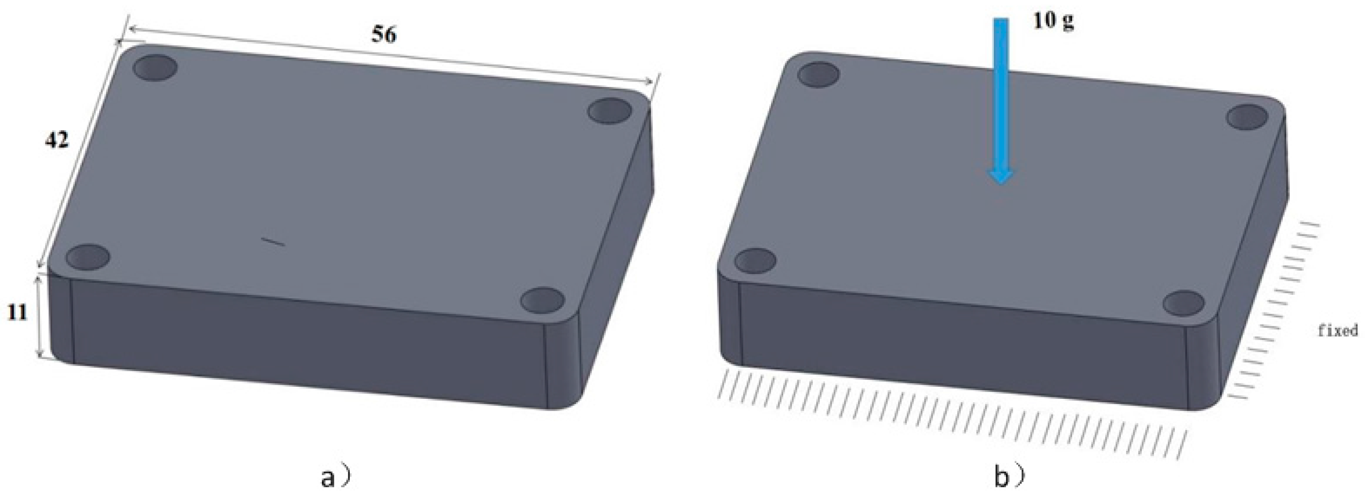
Figure 9.
The stress distribution of the sensor mount.

Figure 10.
(a) The sensor mount after shell operation. (b) The internal structure of the sensor mount after reconstruction.
Figure 10.
(a) The sensor mount after shell operation. (b) The internal structure of the sensor mount after reconstruction.

Figure 11.
The simulation of the reconstructed sensor mount.

Table 1.
Compression structure unit.
| Structure | Bearing Characteristics | Geometric Features | Picture |
|---|---|---|---|
| diatoms | pressure | Planar structure |  |
| trees | pressure | Dendritic structure |  |
Table 2.
Torsional and bending structural unit.
| Structure | Bearing Characteristics | Geometric Features | Picture |
|---|---|---|---|
| bamboo | moment and torque | Cylindrical structure |  |
| rhubarb | moment | Rectangular structure |  |
Table 3.
Elastic unit.
| Structure | Bearing Characteristics | Geometric Features | Picture |
|---|---|---|---|
| Leaf spring | Impact | Arch structure |  |
| Disc spring | Impact | Circular arched structure |  |
Table 4.
Units and their performance.
| Structure | Picture | Performance |
|---|---|---|
| pyramid |  | light weight heat dissipation |
| honeycomb |  | resist compression energy absorbing |
| foam |  | resist impact energy absorbing |
Table 5.
The structural parameters of the selected bow structure units.
| Units | a/mm | m/mm | n/mm |
|---|---|---|---|
| 1 | 2.6 | 2.7 | 4.6 |
| 2 | 2.6 | 3.1 | 4.6 |
| 3 | 2.4 | 3.1 | 4.6 |
| 4 | 2.8 | 3.1 | 4.6 |
| 5 | 2.6 | 3.1 | 4.3 |
| 6 | 2.6 | 3.1 | 4.9 |
Table 6.
The structure-performance database of the selected bow structure units.
| Units | 1 | 2 | 3 | 4 | 5 | 6 | |
|---|---|---|---|---|---|---|---|
| Parameter | a | 2.6 | 2.6 | 2.4 | 2.8 | 2.6 | 2.6 |
| m | 2.7 | 3.1 | 3.1 | 3.1 | 3.1 | 3.1 | |
| n | 4.6 | 4.6 | 4.6 | 4.6 | 4.3 | 4.9 | |
| Young’s modulus/GPa | 2.12 | 2.50 | 2.70 | 2.61 | 2.47 | 2.64 | |
| Equivalent yield stress/MPa | 164.0 | 201.0 | 214.1 | 199.6 | 189.0 | 212.3 | |
| yield displacement/mm | 7.8 | 8.1 | 8 | 7.7 | 7.7 | 8.1 | |
| Weight/g | 0.73 | 0.79 | 0.78 | 0.80 | 0.74 | 0.83 | |
| energy absorption capacity at elastic stage/J | whole | 3.11 | 3.99 | 4.2 | 3.77 | 3.57 | 4.20 |
| Specific weight | 4.26 | 5.05 | 5.38 | 4.71 | 4.82 | 5.06 | |
| energy absorption capacity at initial destruction/J | whole | 9.76 | 13.74 | 14.65 | 13.99 | 12.22 | 15.85 |
| Specific weight | 13.37 | 17.39 | 18.78 | 17.49 | 16.51 | 19.10 | |
Note: Each unit has the three same samples that were tested, the stress-strain curves of the samples of each unit are very consistent and the data in this table is the average value of the samples of each unit.
© 2018 by the authors. Licensee MDPI, Basel, Switzerland. This article is an open access article distributed under the terms and conditions of the Creative Commons Attribution (CC BY) license (http://creativecommons.org/licenses/by/4.0/).
Share and Cite
MDPI and ACS Style
Tang, L.; Zhang, Q.; Liang, K.; Zhao, X.; Zhang, Z. Discrete Optimization of Internal Part Structure via SLM Unit Structure-Performance Database. Metals 2018, 8, 45. https://doi.org/10.3390/met8010045
AMA Style
Tang L, Zhang Q, Liang K, Zhao X, Zhang Z. Discrete Optimization of Internal Part Structure via SLM Unit Structure-Performance Database. Metals. 2018; 8(1):45. https://doi.org/10.3390/met8010045
Chicago/Turabian StyleTang, Li, Qingbiao Zhang, Keshan Liang, Xiqing Zhao, and Zhixiong Zhang. 2018. "Discrete Optimization of Internal Part Structure via SLM Unit Structure-Performance Database" Metals 8, no. 1: 45. https://doi.org/10.3390/met8010045
Note that from the first issue of 2016, this journal uses article numbers instead of page numbers. See further details here.