Direct Numerical Study of a Molten Metal Drop Solidifying on a Cold Plate with Different Wettability


1
School of Transportation Engineering, Hanoi University of Science and Technology, No. 01 Dai Co Viet, Hai Ba Trung, Hanoi 100000, Vietnam
2
Institute of Mechanics, Vietnam Academy of Science and Technology, 18 Hoang Quoc Viet, Cau Giay, Hanoi 100000, Vietnam
*
Author to whom correspondence should be addressed.
Metals 2018, 8(1), 47; https://doi.org/10.3390/met8010047
Submission received: 21 December 2017
/
Revised: 3 January 2018
/
Accepted: 8 January 2018
/
Published: 11 January 2018
(This article belongs to the Special Issue Rapid Solidification Processing)
Abstract
:This paper presents a direct numerical simulation of solidification of a molten metal drop on a cold plate with various wettability by an axisymmetric front-tracking method. Because of the plate kept at a temperature below the fusion value of the melt, a thin solid layer forms at the plate and evolves upwards. The numerical results show that the solidifying front is almost flat except near the triple point with a high solidification rate at the beginning and final stages of solidification. Two solid-to-liquid density ratios ρsl = 0.9 (volume change) and 1.0 (no change in volume), with two growth angles φ0 = 0° and 12° are considered. The presence of volume change and a non-zero growth angle results in a solidified drop with a conical shape at the top. The focusing issue is the effects of the wettability of the plate in terms of the contact angle φ0. Increasing the contact angle in the range of 45° to 120° increases time for completing solidification, i.e., solidification time. However, it has a minor effect on the conical angle at the top of the solidified drop and the difference between the initial liquid and final solidified heights of the drop. The effects of the density ratio and growth angle are also presented.
1. Introduction
Liquid–solid phase change process in drops sessile on a cold solid surface has been of important interest in recent years due to its wide appearance in nature and engineering problems such as water drops freezing on wind turbine blades and electric cables, and metal drops solidifying in the crystallization and atomization processes. Because of different types of solid surfaces and drop liquid materials, drops solidify from the surface at different contact angles, i.e., different wettability. Accordingly, many works related to this problem have been carried out.
Experimentally, Huang et al. [1] investigated freezing of water drops on a cold plate under various contact angles (in the range of 76–154.9°). They found that the contact angle has a remarkable effect on the water drop freezing time: it increases with an increase in the contact angle. Similarly, Boinovich et al. [2] performed an experiment to investigate the effects of wettability of the cold plate on the water drop freezing. Hao et al. [3] focused on not only the freezing time but also the freezing delay time of sessile water drops on different wettability surfaces, i.e., the contact angle varying in the range of 60–157.6°. They showed that larger contact angles resulted in longer freezing time (i.e., time from the start of the nucleation to the complete freezing). Jin et al. [4] reported experimental observations of the successive freezing processes of water drops on an ice surface. The drop freezing time, the contact angle, the diameter and height of the ice bead were strongly affected by both surface temperature and the initial height of the water drop. Some other experimental investigations on the water drop freezing process can be found in [5,6,7,8,9], but have not considered in detail the effects of the contact angle at the plate.
Instead of using water, Satunkin [10] used various materials such as silicon (Si), germanium, and indium antimonide to determine the growth and wetting (i.e., contact) angles of the crystallized melt drops. Itoh et al. [11] crystallized Si drops on a Si3N4 for applications of solar cells. In Hariharan and Ravi’s invention [12], the author crystallized Si drops on plates by first melting piles of Si powder to form molten Si drops on a plate, and then cooling the plates. The shape of the crystallized Si drops depends on the plate materials and roughness, i.e., contact angles.
Theoretically, Zhang et al. [13] performed the modelling of the freezing process of water drops combining with the experimental study to produce frozen drops at various contact angles. However, the model results have not shown conical shapes observed in the experiments. In another theoretical work [14], the author developed a model to simulate the freezing behaviors of a water drop on a cold plate. The authors have not considered the effects of the contact angle.
A few numerical simulations can be found in Schultz et al. [15] for water, Virozub et al. [16] for water and some semiconductor materials, and Chaudhary and Li [17] for water. More comprehensive works can be found in our previous studies [18,19] in which various parameters have been investigated. However, in the above-mentioned works, detailed investigations on the effects of the contact angle have not been considered.
It is evident that detailed direct numerical simulations of the solidification process of a molten metal drop (i.e., with the Prandtl number of around 0.01) under the effect of the contact angle are rarely found in the literature. This gap motivates our present study since the problem is extremely important not only in academia but also in nature and engineering applications [10,11,12,20,21]. In this study, we present a direct numerical investigation on the drop solidification on a cold plate with various contact angles. The method used is an axisymmetric front tracking/finite difference technique [22,23].
2. Numerical Problem and Method
Figure 1 shows the configuration of an axisymmetric molten drop solidifying on a cold plate with the presence of three interfaces meeting at a triple point. At this point, the growth angle φgr is specified as
where φs and φl are the solid and liquid angles with s and l denoting solid and liquid, respectively [19,24,25]. Initially, the drop is assumed to be a section of a sphere, which is specified by a contact angle φ0 and the wetting radius Rw at the plate. The plate is kept at constant temperature Tc below the fusion value of the drop liquid Tm. As a consequence, a thin solid layer forms on the plate at the start. As the solidification proceeds, the solidifying interface moves upwards with a normal velocity Vn given as
where ρ and Lh is the density and latent heat, respectively. , the heat flux at the solidification interface, is given by
where k is the thermal conductivity. It, as an interfacial heat source, is also introduced to the energy equation that is solved in the entire domain
where δ(x − xf) is the Dirac’s Delta function with f denoting interface. Cp is the heat capacity. Another interfacial source known as the interfacial tension force acting on the liquid–gas interface (the last term in the following equation), is accounted for in the momentum equation
here, u = (u, v) is the velocity vector, p is the pressure, g is the acceleration due to gravity. The superscript T denotes the transpose. σ is the interfacial tension that is linearly varied with the temperature [19], i.e., (σ0 and βδ are the surface tension coefficient at a reference temperature and the Marangoni tension coefficient). κ is twice the mean curvature, and nf is the unit normal vector to the interface. f is the forcing term used to impose the no-slip condition on the solid–fluid interface [24,25,26]. The problem is closed by the following continuity equation with proper boundary conditions shown in Figure 1,
This equation accounts for volume change upon solidification [18,19]. Equations (4)–(6), in terms of one-fluid representation, are for fluids assumed immiscible, incompressible and Newtonian. We also assume that the thermal and fluid properties are constant in each phase, and the effect of natural convection is neglected [18,19].
The above-mentioned equations are solved by the front-tracking method combined with an interpolation technique for three phase computations [18,19,24,25]. The interfaces are represented by connected elements moving on the uniformly fixed grid. We use the predictor-corrector scheme for time integration and centered difference for spatial derivatives. Detailed description of the method can be found in our previous works [18,19,24,25].
We choose the effective radius of the drop R = as a length scale and as a time scale (V0 is the volume of the initial liquid drop). The velocity scale is Uc = R/τc. The problem is governed by the Prandtl number Pr, Stefan number St, Bond number Bo, Weber number We, Marangoni number Ma, dimensionless initial temperature of the liquid θ0, density ratios ρsl and ρgl, viscosity ratio μgl, thermal conductivity ratios ksl and kgl, heat capacity ratios Cpsl and Cpgl
The dimensionless time and temperature are τ = t/τc and , respectively. The domain size is chosen as W × H = 3R × 3R with a grid resolution of 482 × 482. In this paper, we are interested in the effects of the contact angle φ0 for two solid-to-liquid density ratios and two growth angles, and thus other parameters are kept constant, i.e., St = 0.1, Pr = 0.01, Bo = 0.1, Ma = 10, We = 0.1, ρgl = μgl = 0.05, ksl = Cpsl = Cpgl = 1.0, kgl = 0.005, and θ0 = 1. As demonstrated in our previous works [18,19], Ma in order of 10 has a minor effect on the solidification process, and thus the Marangoni effect with θ0 = 1 can be negligible. These parameters correspond to a liquid drop of metals or semiconductor materials, such as silicon or germanium (i.e., Pr ≅ 0.01), with R of a few millimeters [10,11].
Method validations have been carefully carried out in our previous works [18,19,27]. Such some validations are shown in Figure 2. Figure 2a compares the predicted profiles with the experimental ones of a water drop reported by Anderson et al. [5]. Details of this comparison can be found in Vu et al. [19]. Figure 2b shows the results of the silicon drop crystallization, reproduced by the method, in comparison with the solidified drop reported in [10] (for more details of this comparison, see our recent work [27]). It is observed that the numerical results are in good agreement with the experimental data, indicating that the method can accurately predict the drop shape after complete solidification.
3. Results and Discussion
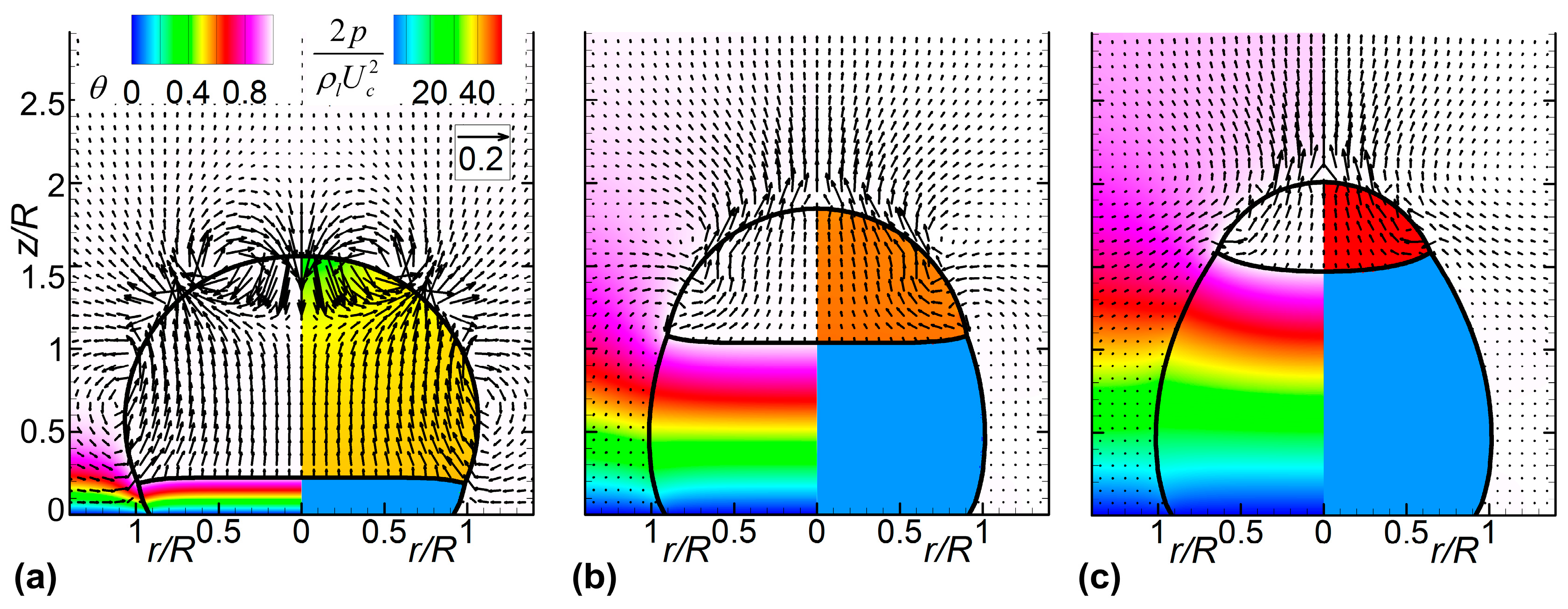
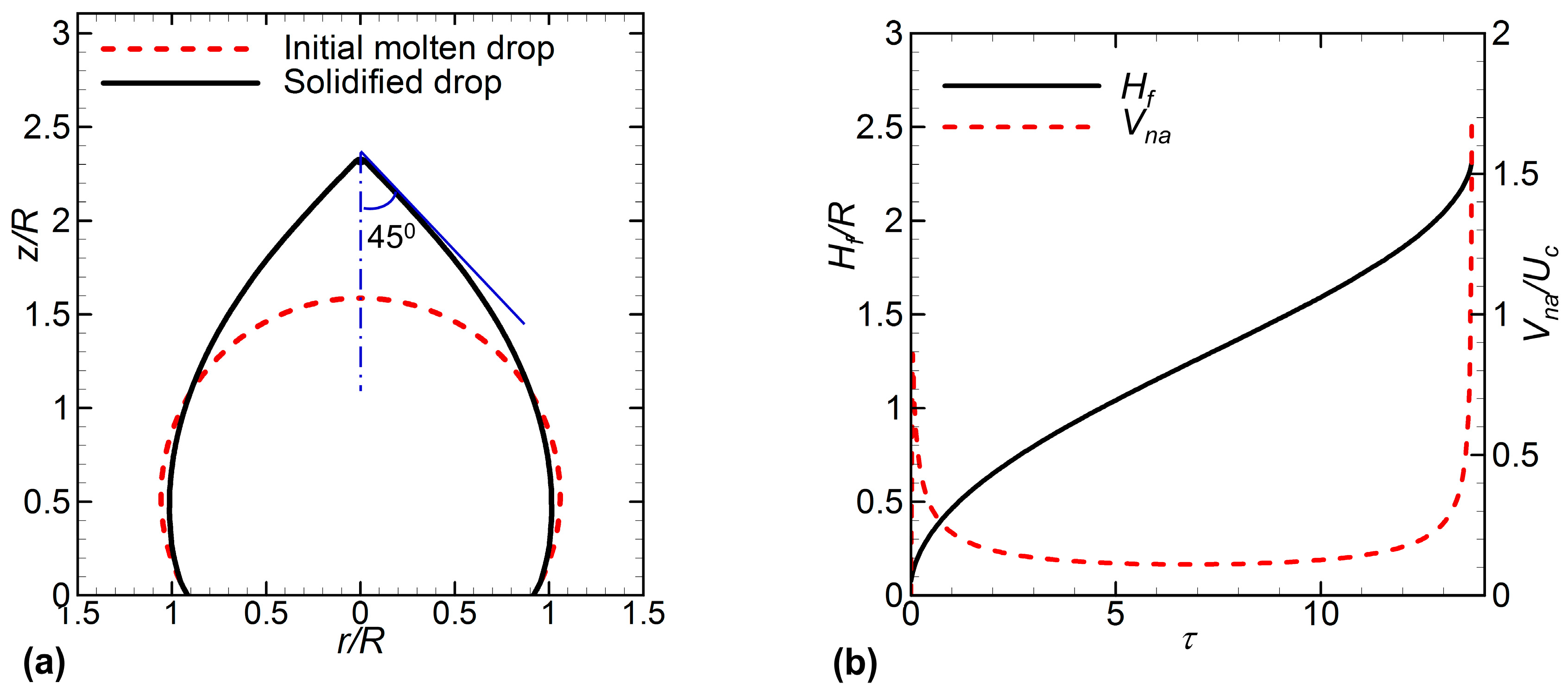
Figure 3 shows the temporal evolution of the molten drop solidifying on a cold plate with ρsl = 0.9. The contact angle is set to 120°. The growth angle is 12°. The drop solidifies from a static state at which the shape of the drop is confined by the surface tension and gravity forces. Thus, at the beginning, the gravity induces a downward flow in the region around the top of the drop to reduce the drop height. In addition, volume expansion induced by density difference between the solid and liquid phases (i.e., ρsl = 0.9) results in a drift away from the solidifying front [19,28]. This drift hits the downward flow within the drop, resulting in the circulations around the drop as shown at τ = 0.2 in Figure 3a. At a later time, there is only the drift induced by volume change in the liquid phase because the gravity force has balanced with the surface tension force (Figure 3a,b). This drift leads to expansion in the vertical direction rather than in the radial direction [6]. This effect presents as the size of the drop is small (i.e., in order of a few hundred micrometers). As a result, the height of the solidifying drop increases in time, as shown in Figure 3. We can also see that during solidification, the temperature in the liquid phase keeps at the melting value, and the solid–liquid front is almost flat except near the tri-junction and during the last stages of solidification [15]. The shape of the solidified drop is very different from the molten one, with an apex at the axis of symmetry, as shown in Figure 4a, because of density change. The conical angle at the top is around 45°. Figure 4 also indicates that the growth rate is different at different stages of solidification. At the beginning of solidification, the solidification process proceeds fast due to the large temperature difference between the liquid and the plate. Thereafter, the growth rate keeps decreasing until the final stage, during which it climbs up again. This tendency is in accordance with Nauenberg’s theory [29].
Next, we consider the effects of the contact angle on the solidification process.
Figure 5a shows the evolution of the solidification front for two cases φ0 = 60° and φ0 = 105° with ρsl = 0.9 and φgr = 12°. The behavior of the solidification front in Figure 5 is similar to the case shown in Figure 3 where the interface evolves from an almost flat shape to a concave-up circular arc. The process is similar to that reported by Ajaev and Davis [30]. The initial shape also affects the solidification rate. Since the initial volumes of two cases are identical, i.e., identical dimensionless parameters, smaller initial contact angles correspond to wider wetted drop radii. Therefore, decreasing the initial contact angle promotes the solidification rate and reduces time required to complete solidification as shown in Figure 5.
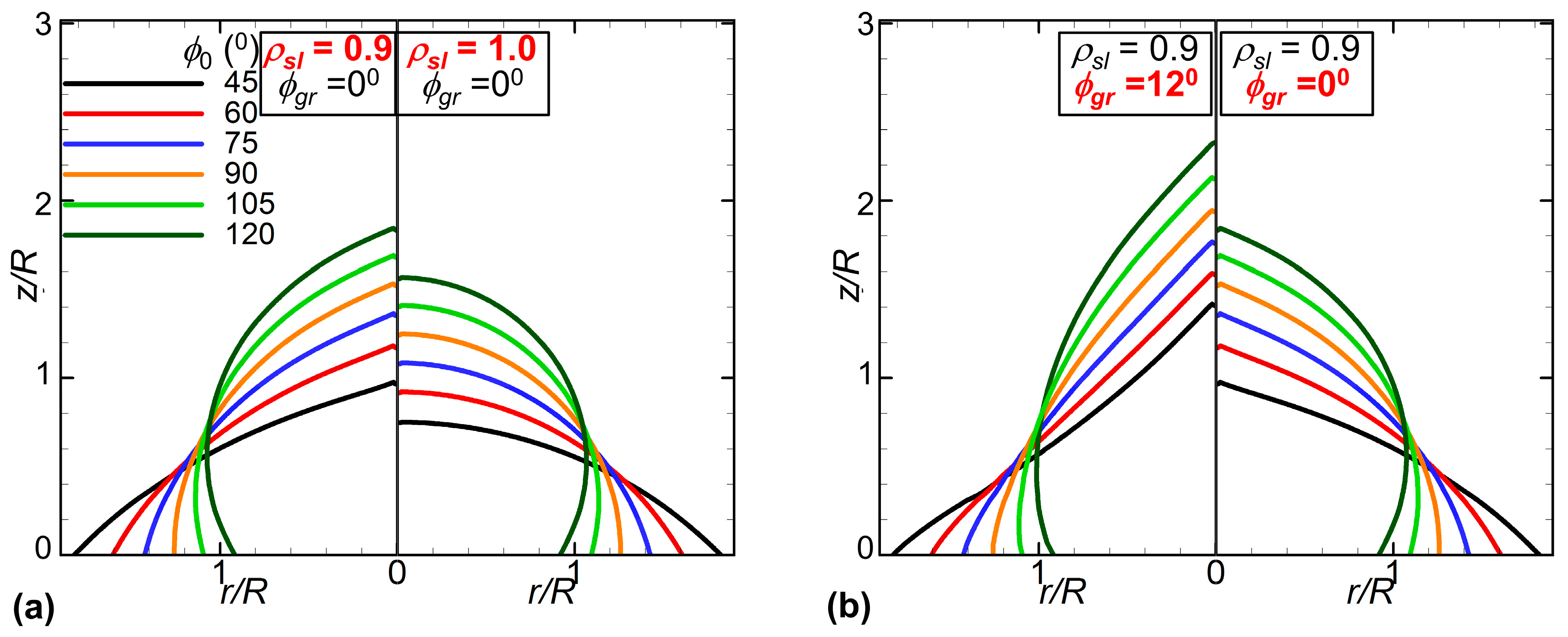
Because of a wider wetted drop radius, decreasing the contact angle from 105° to 60° leads to a decrease in the drop height and thus the solidified drop height. This effect is evidently seen in Figure 6 that shows the shape of the solidified drop at various contact angles in the range of 45–120° with and without volume change and with two growth angles φgr = 0° and φgr = 12°. Unlike the case of no volume change and φgr = 0° (right frame of Figure 6a), volume expansion and φgr = 12° induce a solidified drop with a cone at the top. Figure 6 also confirms that the growth angle and volume expansion have strong influence on the final product of the solidification process, making the solidified drop profoundly different from the initial liquid drop. The solidified drop is more conical as there’s the presence of volume expansion or non-zero growth angle (Figure 6).
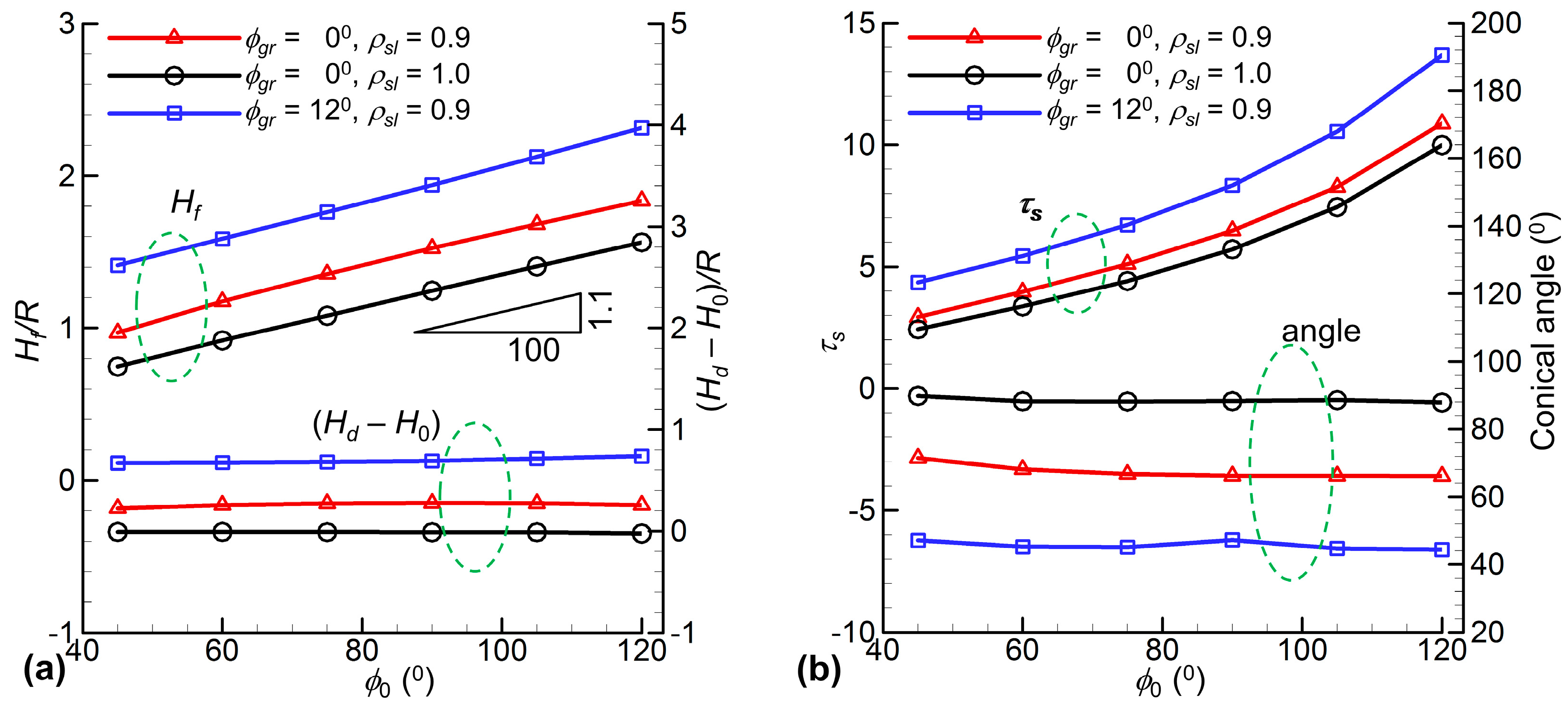
The effect of the contact angle φ0 is more clearly seen from Figure 7. As also shown in Figure 6, Figure 7a indicates that the solidified drop height Hf after complete solidification, linearly increases with the contact angle, with a slope of 1.1R per 100°. Figure 7a also indicates that this slope applies for two density ratios and two growth angles. Thus, the contact angle has a very minor effect on the height difference between the final solidified drop and the initial liquid one, Hd–H0. However, the height of the solidified drop and thus the height difference, Hd–H0, increase with an increase in the growth angle or with a decrease in the density ratio [18,19]. Because the drop height increases, the solidification process takes longer time to complete as the contact angle increases in the range of 45° to 120°, as shown in Figure 7b. This tendency is the same as the experimental observations (e.g., for water [1]). In addition, the volume expansion increases time for complete solidification. Similarly, increasing the growth angle also slows down the process and thus increases the solidification time, as shown in Figure 7b [19].
In contrast to the significant effects on the solidification time, the contact angle has a minor effect on the formation of the conical angle at the top of the solidified drop as shown in Figure 7b. For instance, the angle at the top is around 90° for φgr = 0° in the cases of no volume change, but it decreases to 45° for φgr = 12° and ρsl = 0.9 (Figure 7b). This shows that the conical angle at the top increases with an increase in the density ratio or with a decrease in the growth angle, as shown in Figure 7b.
4. Conclusions
We have presented a detailed numerical work of a liquid metal drop solidifying on a cold plate by the front-tracking method. We focus on the effects of the initial shape of the drop, in terms of the contact angle φ0, for two solid-to-liquid density ratios (ρsl = 0.9 and 1.0) and two growth angles (φgr = 0° and 12°). The solidified drop with a cusp at the top is profoundly different from the initial liquid one if volume expansion (i.e., ρsl = 0.9) and non-zero growth angle are presented. They, ρsl = 0.9 and φgr = 12°, also result in a longer solidification time as compared to ρsl = 1.0 (no change in volume) and φgr = 0°. The numerical results obtained from varying φ0 in the range of 45–120° show that increasing the growth angle increases the solidification time and the solidified drop height. However, the contact angle has minor effects on the height difference between the solidified drop and the liquid drop as well as the conical angle at the top of the solidified drop. Meanwhile, this conical angle increases with an increase in ρsl or with a decrease in φgr.
The numerical results of the present study can be used for applications in metal atomization or crystal growth of such materials as silicon or germanium. For instance, in crystallization of molten silicon drops, with a diameter of a few millimeters, from substrates for spherical solar cells [31], the substrate material and roughness, i.e., the contact angle, plays an important role in the form of the crystallized drop. In addition, according to the present results, a conical angle of around 45° always presents at the top for various contact angles, and thus it needs further processes (e.g., grinding) to produce spherical drops for solar cell applications.
Acknowledgments
This research is funded by Vietnam National Foundation for Science and Technology Development (NAFOSTED) under grant number 107.03-2017.01. We are grateful to John C. Wells at Ritsumeikan University (Japan) for facilitating our computing resources.
Author Contributions
Cuong T. Nguyen and Duong K. Tran performed simulations and analyzed the data; Truong V. Vu wrote the paper.
Conflicts of Interest
The authors declare no conflict of interest.
References
- Huang, L.; Liu, Z.; Liu, Y.; Gou, Y.; Wang, L. Effect of contact angle on water droplet freezing process on a cold flat surface. Exp. Therm. Fluid Sci. 2012, 40, 74–80. [Google Scholar] [CrossRef]
- Boinovich, L.; Emelyanenko, A.M.; Korolev, V.V.; Pashinin, A.S. Effect of Wettability on Sessile Drop Freezing: When Superhydrophobicity Stimulates an Extreme Freezing Delay. Langmuir 2014, 30, 1659–1668. [Google Scholar] [CrossRef] [PubMed]
- Hao, P.; Lv, C.; Zhang, X. Freezing of sessile water droplets on surfaces with various roughness and wettability. Appl. Phys. Lett. 2014, 104, 161609. [Google Scholar] [CrossRef]
- Jin, Z.; Cheng, X.; Yang, Z. Experimental investigation of the successive freezing processes of water droplets on an ice surface. Int. J. Heat Mass Transf. 2017, 107, 906–915. [Google Scholar] [CrossRef]
- Anderson, D.M.; Worster, M.G.; Davis, S.H. The case for a dynamic contact angle in containerless solidification. J. Cryst. Growth 1996, 163, 329–338. [Google Scholar] [CrossRef]
- Enríquez, O.R.; Marín, Á.G.; Winkels, K.G.; Snoeijer, J.H. Freezing singularities in water drops. Phys. Fluids 2012, 24, 091102. [Google Scholar] [CrossRef]
- Snoeijer, J.H.; Brunet, P. Pointy ice-drops: How water freezes into a singular shape. Am. J. Phys. 2012, 80, 764. [Google Scholar] [CrossRef]
- Hu, H.; Jin, Z. An icing physics study by using lifetime-based molecular tagging thermometry technique. Int. J. Multiph. Flow 2010, 36, 672–681. [Google Scholar] [CrossRef]
- Jin, Z.; Sui, D.; Yang, Z. The impact, freezing, and melting processes of a water droplet on an inclined cold surface. Int. J. Heat Mass Transf. 2015, 90, 439–453. [Google Scholar] [CrossRef]
- Satunkin, G.A. Determination of growth angles, wetting angles, interfacial tensions and capillary constant values of melts. J. Cryst. Growth 2003, 255, 170–189. [Google Scholar] [CrossRef]
- Itoh, H.; Okamura, H.; Nakamura, C.; Abe, T.; Nakayama, M.; Komatsu, R. Growth of spherical Si crystals on porous Si3N4 substrate that repels Si melt. J. Cryst. Growth 2014, 401, 748–752. [Google Scholar] [CrossRef]
- Hariharan, A.V.; Ravi, J. Laser Conversion of High Purity Silicon Powder to Densified Garnular Forms. U.S. Patent 9067792B1, 30 June 2015. [Google Scholar]
- Zhang, H.; Zhao, Y.; Lv, R.; Yang, C. Freezing of sessile water droplet for various contact angles. Int. J. Therm. Sci. 2016, 101, 59–67. [Google Scholar] [CrossRef]
- Zhang, X.; Wu, X.; Min, J.; Liu, X. Modelling of sessile water droplet shape evolution during freezing with consideration of supercooling effect. Appl. Therm. Eng. 2017, 125, 644–651. [Google Scholar] [CrossRef]
- Schultz, W.W.; Worster, M.G.; Anderson, D.M. Solidifying sessile water droplets. In Interactive Dynamics of Convection and Solidification; Kluwer Academic Publishers: Dordrecht, The Netherlands, 2001; pp. 209–226. ISBN 978-90-481-5719-8. [Google Scholar]
- Virozub, A.; Rasin, I.G.; Brandon, S. Revisiting the constant growth angle: Estimation and verification via rigorous thermal modeling. J. Cryst. Growth 2008, 310, 5416–5422. [Google Scholar] [CrossRef]
- Chaudhary, G.; Li, R. Freezing of water droplets on solid surfaces: An experimental and numerical study. Exp. Therm. Fluid Sci. 2014, 57, 86–93. [Google Scholar] [CrossRef]
- Vu, T.V.; Tryggvason, G.; Homma, S.; Wells, J.C.; Takakura, H. A front-tracking method for three-phase computations of solidification with volume change. J. Chem. Eng. Jpn. 2013, 46, 726–731. [Google Scholar] [CrossRef]
- Vu, T.V.; Tryggvason, G.; Homma, S.; Wells, J.C. Numerical investigations of drop solidification on a cold plate in the presence of volume change. Int. J. Multiph. Flow 2015, 76, 73–85. [Google Scholar] [CrossRef]
- Cao, Y.; Wu, Z.; Su, Y.; Xu, Z. Aircraft flight characteristics in icing conditions. Prog. Aerosp. Sci. 2015, 74, 62–80. [Google Scholar] [CrossRef]
- Dalili, N.; Edrisy, A.; Carriveau, R. A review of surface engineering issues critical to wind turbine performance. Renew. Sustain. Energy Rev. 2009, 13, 428–438. [Google Scholar] [CrossRef]
- Vu, T.V.; Homma, S.; Tryggvason, G.; Wells, J.C.; Takakura, H. Computations of breakup modes in laminar compound liquid jets in a coflowing fluid. Int. J. Multiph. Flow 2013, 49, 58–69. [Google Scholar] [CrossRef]
- Unverdi, S.O.; Tryggvason, G. A front-tracking method for viscous, incompressible, multi-fluid flows. J. Comput. Phys. 1992, 100, 25–37. [Google Scholar] [CrossRef]
- Vu, T.V.; Truong, A.V.; Hoang, N.T.; Tran, D.K. Numerical investigations of solidification around a circular cylinder under forced convection. J. Mech. Sci. Technol. 2016, 30, 5019–5028. [Google Scholar] [CrossRef]
- Vu, T.V.; Wells, J.C. Numerical simulations of solidification around two tandemly-arranged circular cylinders under forced convection. Int. J. Multiph. Flow 2017, 89, 331–344. [Google Scholar] [CrossRef]
- Liao, C.-C.; Chang, Y.-W.; Lin, C.-A.; McDonough, J.M. Simulating flows with moving rigid boundary using immersed-boundary method. Comput. Fluids 2010, 39, 152–167. [Google Scholar] [CrossRef]
- Vu, T.V. Three-phase computation of solidification in an open horizontal circular cylinder. Int. J. Heat Mass Transf. 2017, 111, 398–409. [Google Scholar] [CrossRef]
- Sun, Y.; Beckermann, C. Effect of solid–liquid density change on dendrite tip velocity and shape selection. J. Cryst. Growth 2009, 311, 4447–4453. [Google Scholar] [CrossRef]
- Nauenberg, M. Theory and experiments on the ice–water front propagation in droplets freezing on a subzero surface. Eur. J. Phys. 2016, 37, 045102. [Google Scholar] [CrossRef]
- Ajaev, V.S.; Davis, S.H. The effect of tri-junction conditions in droplet solidification. J. Cryst. Growth 2004, 264, 452–462. [Google Scholar] [CrossRef]
- Taira, K.; Nakata, J. Catching rays. Nat. Photonics 2010, 4, 602–603. [Google Scholar] [CrossRef]
Figure 1.
A molten metal drop solidifying on a cold plate: (a) computational domain and (b) enlarged view at the triple point.
Figure 1.
A molten metal drop solidifying on a cold plate: (a) computational domain and (b) enlarged view at the triple point.
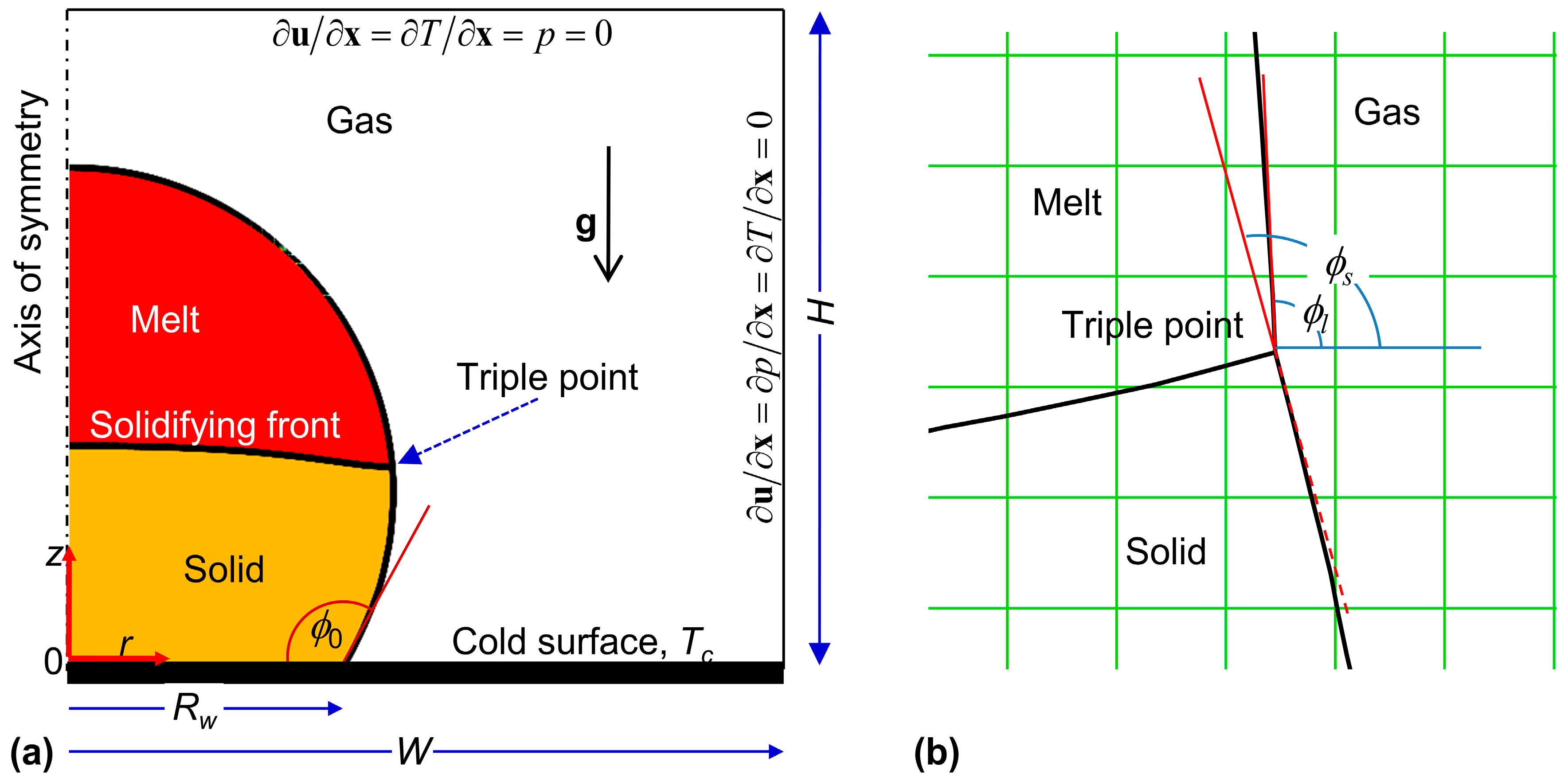
Figure 2.
(a) Comparison of the predicted profiles (solid line) with the experimental ones [5] for a water drop ρsl = 0.9 and φgr = 0°; (b) Comparison of the predicted profile (right) with the experimental one of Satunkin [10] (left) for a Si drop with ρsl = 0.92 and φgr = 12° (the solid line on the right is the drop shape after complete solidification, and the figure is taken from [27]).
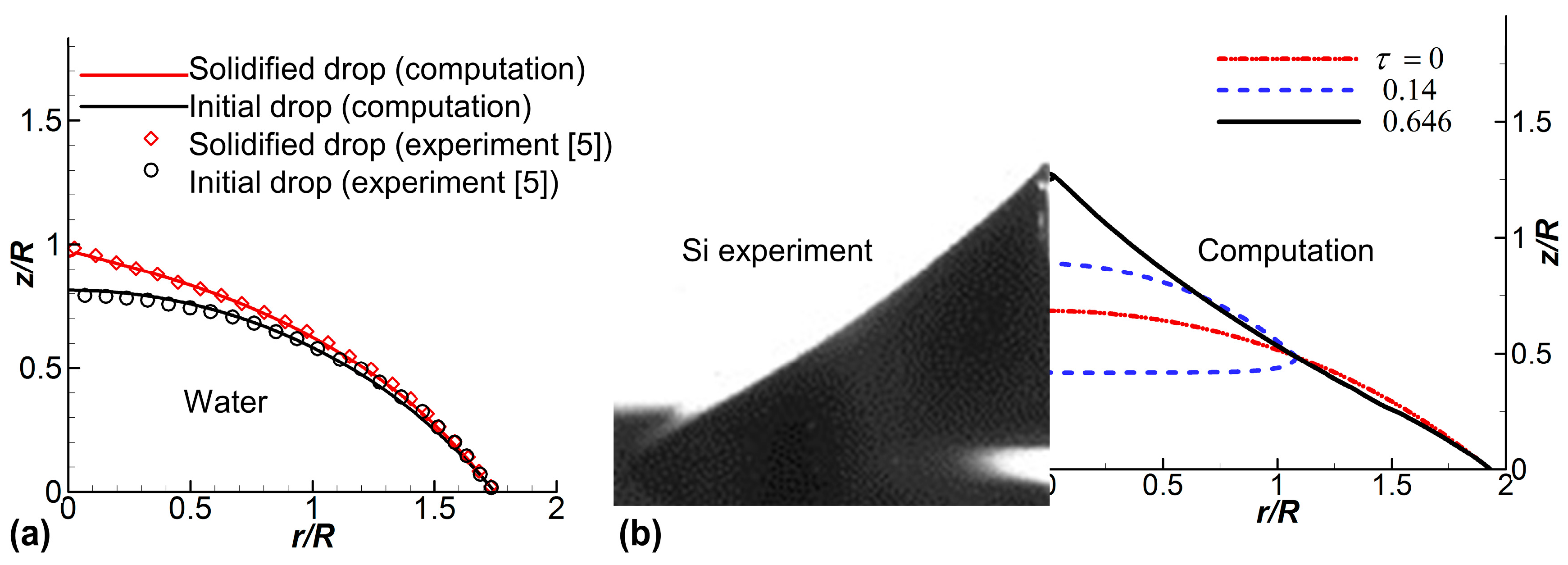
Figure 3.
Evolution of the solidifying front with the temperature (left) and pressure (right) fields at (a) τ = 0.2, (b) τ = 5.0, and (c) τ = 9.24. The velocity is normalized by Uc. The parameters are ρsl = 0.9, φ0 = 120° and φgr = 12°.
Figure 3.
Evolution of the solidifying front with the temperature (left) and pressure (right) fields at (a) τ = 0.2, (b) τ = 5.0, and (c) τ = 9.24. The velocity is normalized by Uc. The parameters are ρsl = 0.9, φ0 = 120° and φgr = 12°.

Figure 4.
(a) Solidified drop profile after complete solidification (solid line) and (b) variation with respect to time of the average height Hf of the solidifying front and the average solidifying rate Vna normalized by Uc. The parameters are the same as in Figure 3.
Figure 4.
(a) Solidified drop profile after complete solidification (solid line) and (b) variation with respect to time of the average height Hf of the solidifying front and the average solidifying rate Vna normalized by Uc. The parameters are the same as in Figure 3.

Figure 5.
Effect of the contact angle on the solidification process for two cases φ0 = 60° and 105°: (a) the evolution of the solidifying front and (b) the average height Hf of the solidifying front. Other parameters: ρsl = 0.9 and φgr = 12°.
Figure 5.
Effect of the contact angle on the solidification process for two cases φ0 = 60° and 105°: (a) the evolution of the solidifying front and (b) the average height Hf of the solidifying front. Other parameters: ρsl = 0.9 and φgr = 12°.
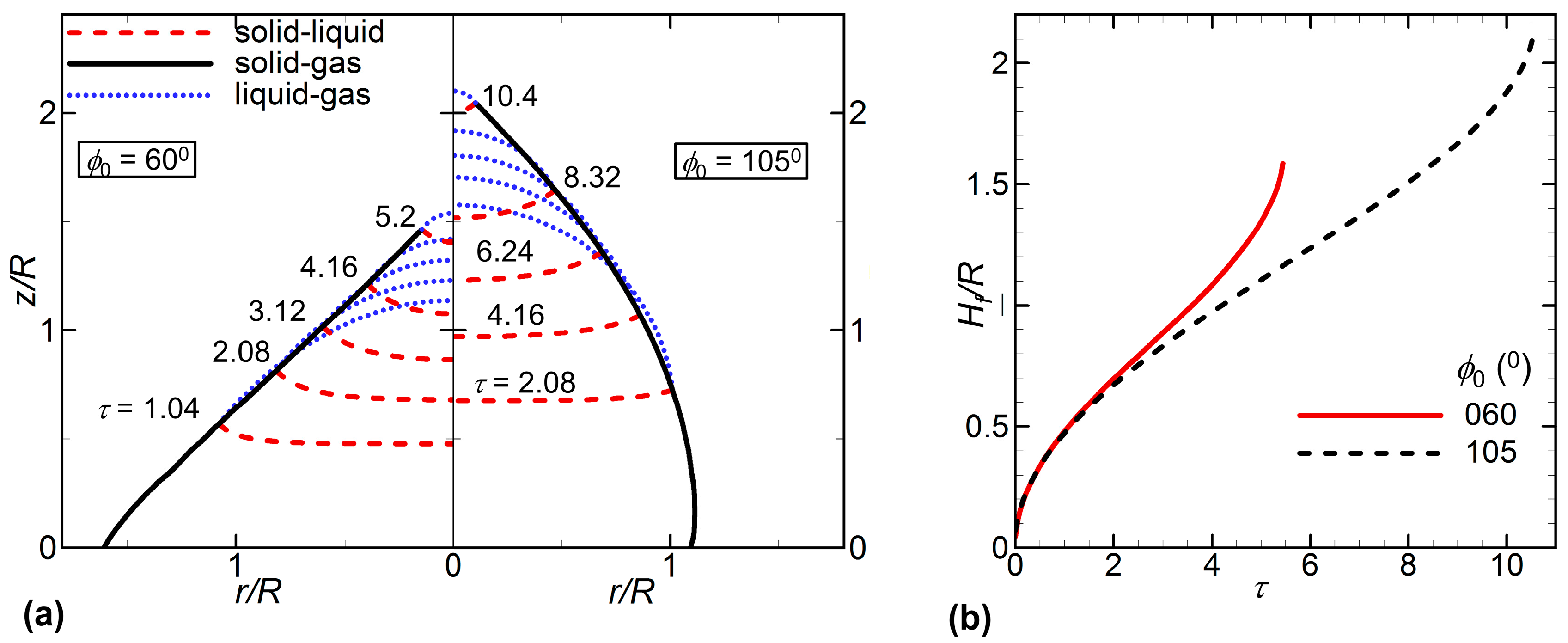
Figure 6.
The solidified drop profiles for various contact angles, two density ratios ρsl = 0.9 and ρsl = 1.0, and two growth angles φgr = 0° and φgr = 12°.
Figure 6.
The solidified drop profiles for various contact angles, two density ratios ρsl = 0.9 and ρsl = 1.0, and two growth angles φgr = 0° and φgr = 12°.

Figure 7.
Effects of the contact angle, density ratio and growth angle on the solidification process: (a) the average height Hf of the solidifying front at the final stage of solidification, and the difference height, Hd–H0, between the final height after complete solidification (Hd) and the initial height (H0); (b) the solidification time and the conical angle at the top of the solidified drop.

© 2018 by the authors. Licensee MDPI, Basel, Switzerland. This article is an open access article distributed under the terms and conditions of the Creative Commons Attribution (CC BY) license (http://creativecommons.org/licenses/by/4.0/).
Share and Cite
MDPI and ACS Style
Vu, T.V.; Nguyen, C.T.; Khanh, D.T. Direct Numerical Study of a Molten Metal Drop Solidifying on a Cold Plate with Different Wettability. Metals 2018, 8, 47. https://doi.org/10.3390/met8010047
AMA Style
Vu TV, Nguyen CT, Khanh DT. Direct Numerical Study of a Molten Metal Drop Solidifying on a Cold Plate with Different Wettability. Metals. 2018; 8(1):47. https://doi.org/10.3390/met8010047
Chicago/Turabian StyleVu, Truong V., Cuong T. Nguyen, and Duong T. Khanh. 2018. "Direct Numerical Study of a Molten Metal Drop Solidifying on a Cold Plate with Different Wettability" Metals 8, no. 1: 47. https://doi.org/10.3390/met8010047
Note that from the first issue of 2016, this journal uses article numbers instead of page numbers. See further details here.