Compositional Approach to Designing Fcc High-Entropy Alloys that Have an Enlarged Equiaxed Zone

Korea Institute of Materials Science, 797 Changwondae-ro, Seongsan-gu, Changwon, Gyeongnam 642-831, Korea
*
Author to whom correspondence should be addressed.
Metals 2018, 8(1), 54; https://doi.org/10.3390/met8010054
Submission received: 26 December 2017
/
Revised: 7 January 2018
/
Accepted: 8 January 2018
/
Published: 13 January 2018
Abstract
:A compositional approach to designing alloys that have an enlarged equiaxed zone is suggested in this study. The partitioning of elements during the solidification of CoCrFeMnNi high-entropy alloy (HEA) was confirmed through a directional solidification quenching experiment. Several HEAs were designed to maximize the effects of constitutional and thermal undercooling by considering factors including solute enrichment at the columnar front and the melting temperatures and thermal conductivities of the individual elements. The newly designed HEAs were shown to have successfully enlarged equiaxed zones, and improved anisotropic properties.
1. Introduction
High-entropy alloys (HEAs), which are composed of five or more elements in equiatomic or nearly equiatomic ratios [1,2], are regarded as base materials for high-performance alloys due to their novel properties [3,4,5]. To commercialize HEAs, more research on their manufacturing processes is required. Previous studies have focused on HEAs made using small-scale casting methods, such as arc melting [5,6]. One challenge that needs to be addressed in HEA research is their mass-scale production.
A CoCrFeMnNi HEA (8 kg) was successfully produced on a pilot-scale by vacuum induction melting (VIM) in our previous work [7]. However, its macrostructure was composed of a considerable amount of columnar structures, with only a few equiaxed structures in the center [7]. This type of macrostructure is known to degrade workability during the subsequent forming processes, because it induces significant deformation anisotropy. Moreover, the columnar structure decreases the reliability of the mechanical properties of castings [8,9]. Therefore, the columnar structure portion is considered to be one of the most important factors governing the practical application of HEA castings. Controlling the casting conditions is the general method used to enlarge the equiaxed zone of the castings [10]. However, there are limitations imposed by the manufacturing equipment and facilities. Therefore, control of the chemical composition in addition to the casting conditions is needed to obtain a substantial enlargement of the equiaxed zone.
In this work, we suggested a compositional approach to designing a HEA with a large portion of equiaxed grains by considering element partitioning during solidification. New HEAs were designed based on the present method, and their macrostructures and deformation anisotropies were confirmed by comparing them with those of equiatomic CoCrFeMnNi HEAs.
2. Materials and Methods
An equi-atomic CoCrFeMnNi HEA called Cantor alloy was prepared by pilot-scale VIM using high-purity elements. The details of pilot-scale casting (Y-block shape, 60 × 110 × 150 mm3) are described in a previous report [7]. The HEA round bar (length: 100 mm, diameter: 4.8 mm) for the directional solidification quenching (DSQ) experiment was machined from the ingot. A DSQ experiment was carried out using a Bridgman-type directional solidification (DS) furnace. The specimen was heated to above its melting temperature. Afterwards, the temperature was lowered by the downward movement of the furnace with a thermal gradient. The solidification rate was 0.5 μm/s, and the specimen was quenched with liquid metal (Ga-In-Sn alloy) after 60 mm of growth. The details of the DSQ experiments are described in previous papers [11,12].
The microstructures of the HEAs were analyzed using optical microscopy (OM) after mechanical polishing and etching with Kalling’s solution. The chemical compositions of the DS specimens were characterized by an electron-probe micro-analyzer (EPMA, Cameca SX100, Gennevilliers, France) at the solid/liquid interface.
The macrostructure and tensile properties of the newly designed HEAs were investigated in small- and pilot-scale vacuum induction melted castings. The cylinder-type tensile specimens (gauge length: 10 mm, gauge diameter: 2.5 mm) were prepared along three different loading directions on the pilot-scale Y-block ingot. These specimens were tested at a strain rate of 0.001 s−1 by a universal testing machine (model: Instron 5982, Norwood, MA, USA).
3. Results and Discussion
3.1. Solute Partitioning Characteristics during Solidification
Investigation of the solute partitioning phenomenon during solidification is necessary, since our new method for alloy design is based on it. It is difficult to know the elemental composition evolution during a real solidification process; therefore, a DSQ experiment on the Cantor alloy was performed to characterize the solute partitioning during solidification.
Figure 1a shows a macroscopic image of the DSQ specimen. The alloy has solidified in one direction, and the solid/liquid interface is located around 60 mm from the bottom, where the growth is finished. This interfacial region is marked with a dotted line in Figure 1b. The solid/liquid interface has planar morphology due to the slow solidification rate, 0.5 μm/s. The chemical composition at the solid/liquid interface of the DSQ specimen is comparable to the composition when solidification is begun, since the DSQ specimen was quenched in the middle of solidification [13,14]. Therefore, EPMA analysis was carried out on a cross-section of the solid/liquid interface in order to calculate the partition coefficient.
Table 1 shows the chemical composition analysis results and equilibrium partition coefficients (ke), calculated by
where is the solid composition at solid/liquid interface, and is the average bulk liquid composition [14]. An element that has a ke value lower or higher than 1 is partitioned into the liquid or solid phase, respectively. If a ke value differs significantly from 1, it is regarded as a severe segregation of the corresponding element. The segregation of Mn into the liquid, interdendritic region, is the most severe. The ke values of Co., Cr, and Fe are higher than 1 and partitioned into the solid. Severe partitioning of elements can affect the columnar or equiaxed structure of castings.
3.2. Design of Alloys with Extended Equiaxed Zone
The nuclei of the equiaxed grain are formed in the bulk undercooled liquid. It is reported that the equiaxed nuclei originate from the compositional fluctuation at the dendritic arms [15], or from the convection of nuclei formed at the chill zone [15]. The driving force of nucleation is proportional to the undercooling (ΔT), which mainly consists of thermal undercooling (ΔTt) and constitutional undercooling (ΔTc) [16]. Constitutional undercooling prevails at the front of the solid/liquid interface due to the solute redistribution during solidification [16]. Not only the solute enrichment at the front of the solid/liquid interface, but also the melting temperature and thermal conductivity of each enriched element need to be considered for an accurate assessment of undercooling.
A schematic diagram of solidification and undercooling in the front of the solid/liquid interface is shown in Figure 2. The black solid lines are the liquidus line (Tm) and the thermal gradient (dT/dx). The region filled with thin black lines corresponds to undercooling. When a melting temperature of solute enriched region increases, the liquidus line moves upward (red line), the ΔTc increases. Meanwhile, ΔTt is affected by the thermal conductivity (k). When the heat flux is constant, the thermal conductivity and the thermal gradient are in an inverse relationship [17]. Also, thermal conductivity of most metals have a similar order regardless of the temperature [17]. Therefore, a higher thermal conductivity in the bulk liquid causes a decrease in the thermal gradient, marked by the blue triangle in Figure 2, and improves the ΔTt. For example, the constitutional and thermal undercooling at the position x can be increased by the amounts marked as and , respectively, when Tm and k were both considered (Figure 2). Consequently, the composition should be adjusted to increase Tm at the columnar front, and reduce thermal gradient.
Undercooling acts as a driving force for both the nucleation of equiaxed grains and growth of columnar grains [18]. When the fraction of equiaxed grains is enough to block the columnar front, the nucleation and growth of equiaxed grains prevails [18]. To maximize the undercooling at the columnar front, elements which cause high Tm and k value must be partitioned into the liquid region.
3.3. Verification of the Alloy Design Approach
It is difficult to predict the change of Tm as the composition changes at the multi-component system. Therefore, we assumed that the Tm of a solid solution could be simplified as the average Tm of all elements, calculated using the rule of mixture. This is not always correct, so we refer to the effect of the element based on binary phase diagrams.
The melting temperature and thermal conductivity at room temperature of the chemical elements used in this study are listed in Table 2. Among the five elements, Cr and Mn have distinct Tm from the average Tm of Cantor alloy. Therefore, we adjusted the composition of Cr and Mn to maximize undercooling. From the ke values (Table 1), it is expected that Mn will be heavily enriched at the solid/liquid interface front. Manganese has the lowest melting temperature (1244 °C) in this set of elements, and will reduce both the melting temperature at the columnar front and the ΔTc. Indeed, it is clear that the addition of Mn reduces the Tm at the Mn-Co., Mn-Cr, and Mn-Fe binary systems [19]. Therefore, to maximize the effect of ΔTc, the Mn content should be reduced. Chromium, having a higher melting temperature (1857 °C), is partitioned into the solid region and increases the overall melting temperature, which has a negative effect on ΔTc. The addition of Cr causes an increase in Tm at the Cr-Fe, Cr-Ni, and Cr-Mn binary systems [19]. Therefore, the Cr content should be reduced.
The addition of other elements was also considered to maximize the effect of constitutional undercooling. Copper and vanadium could be candidates for addition, since they belong to the same period as Co, Cr, Fe, Mn, and Ni in the periodic table. Cu, which has low Tm (1083 °C), is usually segregated to the interdendritic region [20]. This means that Cu plays the same role as Mn, so it is excluded from the additive list. This tendency can be checked at Cu-X (X = Co., Cr, Fe, and Ni) binary phase diagrams [19]. V, having a high Tm (1890 °C), is segregated to the liquid [21]. Therefore, it is expected that the addition of V could maximize the ΔTc. V-X (X = Co., Cr, Fe, Mn, Ni) binary phase diagrams have no consistent tendency as V content increases [19]. V is added anticipating a maximized effect of ΔTc. However, the addition of V causes a decrease in the valence electron concentration (VEC). Since a VEC greater than 8 is required for a fcc single phase to form [22], Ni is added to compensate for the loss of VEC.
As far as thermal undercooling is concerned, the content of Mn, which has the lowest thermal conductivity, should be reduced. The thermal conductivity of V is higher than that of Mn (Table 2); therefore, substituting Mn for V will positively affect the maximization of thermal undercooling, in addition to constitutional undercooling.
Following the above guidelines, we designed three HEAs: V5, V10, and V15, as designated in Table 3. Conventional parameters such as entropy, enthalpy, atomic size difference, and valence electron concentration values were also calculated for comparison with previous studies [1,23], and are listed in Table 3. In the order of V5, V10, and V15, the effect of the ΔT increases. Round bars (45 g, diameter: 13 mm) of the Cantor and the newly designed HEAs were fabricated by small-scale VIM, and their macrostructure and XRD profiles are shown in Figure 3a–e. All HEAs consisted of fcc single phase (Figure 3a). Equiaxed grains were formed at the center of the newly developed HEA round bars, while the Cantor alloy had no equiaxed grains (Figure 3b). The area of the equiaxed zone was shown to increase as the undercooling effect increased. These results show the potential for the compositional approach to enlarging the equiaxed zone.
This approach can also be applied to other alloys. Spittle et al. [24] reported that the addition of Cu or Sn to Al alloys increased the equiaxed zone, while the addition of Zn reduced it. Since Cu has a higher Tm and k than Al, it is generally segregated to the liquid region [20], and Sn, having a lower Tm and k than Al, is segregated to the solid region [25]. Therefore, both Cu and Sn promote undercooling. On the other hand, Zn, having a lower Tm and k than Al, is segregated to the liquid region [26] and negatively affects the undercooling. These variations in Tm can also be inferred from the Al-Cu, Al-Sn, and Al-Zn binary phase diagrams [19].
Both our present work and the experimental results reported by others support the validity of our compositional approach to alloy design.
3.4. Anisotropic Properties of the Newly Designed HEA
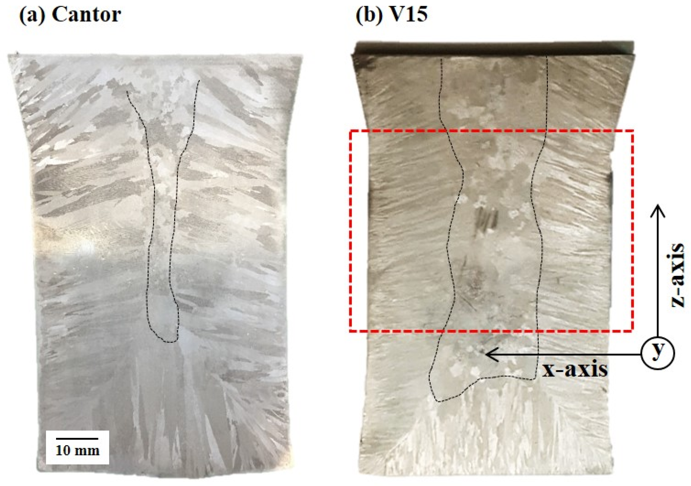
The Cantor and V15 HEAs were fabricated by pilot-scale VIM to examine the anisotropy of the newly designed HEAs. The details of pilot-scale casting are described in previous report [7]. Figure 4a,b shows the macrostructure of the Cantor and V15 HEAs. The V15 alloy that was designed to have a large equiaxed zone showed a volume fraction of equiaxed zone that was 2~3 times higher than that of the Cantor alloy.
To verify the anisotropy of V15, tensile tests along three different loading directions were conducted. All specimens were prepared at the center of the Y-block, indicated by the red dotted line in Figure 4b. The x-axis is parallel to the columnar structure, and the y- and z-axes are perpendicular to the columnar structure. The loading directions are plotted in Figure 4b.
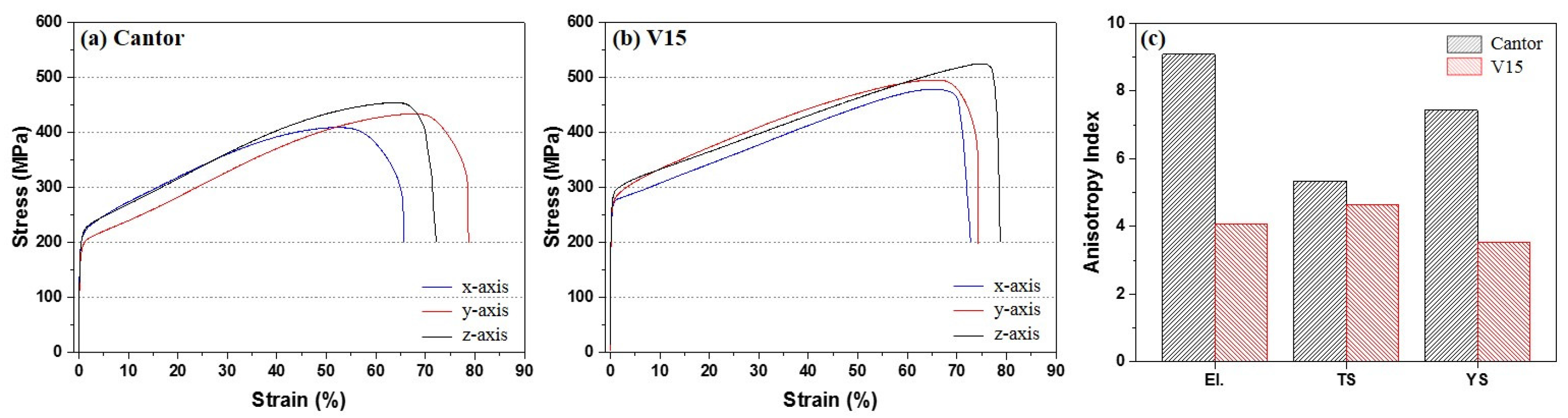
Figure 5 and Table 4 show the tensile properties of the Cantor and V15 alloys. We defined the anisotropy index as Ii = (standard deviation of ix, iy, and iz)/(average of ix, iy, and iz) × 100, where i = YS, TS, and El., and x, y, and z are the loading directions. A high anisotropy index means the material has severely anisotropic properties. The V15 alloy showed higher strengths and elongation than the Cantor alloy. Additionally, all tensile properties, YS, TS, and El., of V15 alloy had lower anisotropy indices than those of the Cantor alloy. These results demonstrate that maximizing thermal and constitutional undercooling can enlarge the equiaxed zone and reduce anisotropy. Moreover, additional improvements of mechanical properties can be achieved.
From the tensile tests of the newly designed HEAs, it is clear that the anisotropy of as-cast HEAs can be moderated by an enlargement of the equiaxed zone. Controlling not only the manufacturing factors, but also the chemical compositions could be the solution for designing alloys with enlarged equiaxed zones, especially given the limitations of manufacturing facilities.
4. Conclusions
In summary, we have developed a compositional approach to enlarging the equiaxed zone of castings using solute partitioning at the columnar front.
- (1)
- Manganese was severely partitioned into the liquid region and had a ke value lower than 1, while Cr was partitioned into the solid region and had a ke value higher than 1. The chemical composition was modified to increase the melting temperature at the solid/liquid interface and reduce the thermal gradient in order to maximize the constitutional and thermal undercooling, respectively.
- (2)
- The macrostructures of V5, V10, and V15 showed the increasing equiaxed zone with increasing undercooling. Both small- and pilot-scale castings showed that maximizing the constitutional and thermal undercooling effectively enlarged the equiaxed zone.
- (3)
- The enlarged equiaxed zone contributes to the moderated anisotropy of the pilot-scale V15 HEA. This approach to alloy design could support the development of new HEA castings containing high proportions of equiaxed zone.
Acknowledgments
This work was supported by the Future Material Discovery Project of the National Research Foundation of Korea (NRF), funded by the Ministry of Science, ICT and Future Planning (MSIP) of Korea (NRF-2016M3D1A1023534).
Author Contributions
Minju Kang, Jong Woo Won, Ka Ram Lim, and Young Sang Na conceived and designed the experiments; Minju Kang and Heoun-Jun Kwon performed the experiments; Minju Kang and Seong Moon Seo analyzed the data; Seong Moon Seo, and Young Sang Na contributed reagents/materials/analysis tools; Minju Kang wrote the paper.
Conflicts of Interest
The authors declare no conflict of interest.
References
- Tsai, M.-H.; Yeh, J.-W. High-Entropy Alloys: A Critical Review. Mater. Res. Lett. 2014, 2, 107–123. [Google Scholar] [CrossRef]
- Cantor, B.; Chang, I.T.H.; Knight, P.; Vincent, A.J.B. Microstructural development in equiatomic multicomponent alloys. Mater. Sci. Eng. A 2004, 375–377, 213–218. [Google Scholar] [CrossRef]
- Raabe, D.; Tasan, C.C.; Springer, H.; Bausch, M. From High-Entropy alloys to High-Entropy Steels. Steel Res. Int. 2015, 86, 1127–1138. [Google Scholar] [CrossRef]
- Na, Y.S.; Lim, K.R. Pilot-scale manufacturing technology and prospect of high-entropy alloy. Trends Met. Mater. Eng. 2017, 30, 50–61. [Google Scholar]
- Huo, W.; Fang, F.; Zhou, H.; Xie, Z.; Shang, J.; Jiang, J. Remarkable strength of CoCrFeNi high-entropy alloy wires at cryogenic and elevated temperatures. Scr. Mater. 2017, 147, 125–128. [Google Scholar] [CrossRef]
- Munitz, A.; Salhov, S.; Hayun, S.; Frage, N. Heat treatment impacts the micro-structure and mechanical properties of AlCoCrFeNi high entropy alloy. J. Alloy. Compd. 2016, 683, 221–230. [Google Scholar] [CrossRef]
- Kang, M.; Won, J.W.; Lim, K.R.; Park, S.H.; Seo, S.M.; Na, Y.S. Microstructure and mechanical properties of As-cast CoCrFeMnNi high entropy alloy. Korean J. Met. Mater. 2017, 55, 732–738. [Google Scholar] [CrossRef]
- Liu, Y.K.; Huang, H.Y.; Xie, J.X. Effect of compression direction on the dynamic recrystallization behavior of continuous columnar-grained CuNi10Fe1Mn alloy. Int. J. Min. Met. Mater. 2014, 22, 851–859. [Google Scholar] [CrossRef]
- Gong, X.; Chou, K. Microstructures of Inconel 718 by Selective Laser Melting. In Proceedings of the TMS 2015 conference, Orlando, FL, USA, 12–19 March 2015. [Google Scholar]
- Campbell, F.C. Metals Fabrication: Understanding the Basics; ASM International: Novelty, OH, USA, 2013. [Google Scholar]
- Seo, S.M.; Kim, I.S.; Lee, J.H.; Jo, C.Y.; Miyahara, H.; Ogi, K. Eta phase and boride formation in directionally solidified Ni-Base superalloy IN792+Hf. Metall. Mater. Trans. A 2007, 38A, 883–893. [Google Scholar] [CrossRef]
- Qi, Y.; Li, J.; Shi, C.; Zhang, Y.; Zhu, Q.; Wang, H. Effect of directional solidification of electroslag remelting on the microstructure and primary carbides in an austenitic hot-work die steel. J. Mater. Process. Technol. 2017, 249, 32–38. [Google Scholar] [CrossRef]
- Seo, S.M.; Lee, J.-H.; Yoo, Y.-S.; Jo, C.-Y.; Miyahara, H.; Ogi, K. Solute redistribution during planar and dendritic growth of directionally solidified Ni-bas superalloy CMSX-10. In Proceedings of the Superalloys 2008 conference, Champion, PA, USA, 14–18 September 2008. [Google Scholar]
- Kurz, W.; Fisher, D.J. Fundamentals of Solidification; Trans Tech Publ. Ltd.: Zurich, Switzerland, 1998. [Google Scholar]
- Hutt, J.; StJohn, D. The origins of the equiaxed zone—Review of theoretical and experimental work. Int. J. Cast Metals Res. 1998, 11, 13–22. [Google Scholar] [CrossRef]
- Yao, X.; Dahle, A.K.; Davidson, C.J.; StJohn, D.H. Effect of solute on the growth rate and the constitutional undercooling ahead of the advancing interface during solidification of an alloy and the implications for nucleation. J. Mater. Res. 2016, 21, 2470–2479. [Google Scholar] [CrossRef]
- Kreith, F.; Black, W.Z. Basic Heat Transfer; Harper & Row: New York, NY, USA, 1980. [Google Scholar]
- Martorano, M.A.; Biscuola, V.B. Predicting the columnar-to-equiaxed transition for a distribution of nucleation undercoolings. Acta Mater. 2009, 57, 607–615. [Google Scholar] [CrossRef]
- ASM Handbook. Alloy Phase Diagrams; ASM International: Novelty, OH, USA, 1992; Volume 3. [Google Scholar]
- Sonkusare, R.; Divya Janani, P.; Gurao, N.P.; Sarkar, S.; Sen, S.; Pradeep, K.G. Phase equilibria in equiatomic CoCuFeMnNi high entropy alloy. Mater. Chem. Phys. 2017. [Google Scholar] [CrossRef]
- Dong, Y.; Zhou, K.; Lu, Y.; Gao, X.; Wang, T.; Li, T. Effect of vanadium addition on the microstructure and properties of AlCoCrFeNi high entropy alloy. Mater. Des. 2014, 57, 67–72. [Google Scholar] [CrossRef]
- Guo, S.; Ng, C.; Lu, J.; Liu, C.T. Effect of valence electron concentration on stability of fcc or bcc phase in high entropy alloys. J. Appl. Phys. 2011, 109, 103505. [Google Scholar] [CrossRef]
- Yang, X.; Zhang, Y. Prediction of high-entropy stabilized solid-solution in multi-component alloys. Mater. Chem. Phys. 2012, 132, 233–238. [Google Scholar] [CrossRef]
- Spittle, J.A.; Brown, S.G.R. Computer simulation of the effects of alloy variables on the grain structures of castings. Acta Metall. 1989, 37, 1803–1810. [Google Scholar] [CrossRef]
- Cruz, K.S.; Ferreira, I.L.; Spinelli, J.E.; Cheung, N.; Gracia, A. Inverse segregation during transient directional solidification of an Al–Sn alloy: Numerical and experimental analysis. Mater. Chem. Phys. 2009, 115, 116–121. [Google Scholar] [CrossRef]
- Zhang, F.; Shen, J.; Yan, X.D.; Sun, J.L.; Sun, X.L.; Yang, Y. Homogenization heat treatment of 2099 Al–Li alloy. Rare Metals 2017, 33, 28–36. [Google Scholar] [CrossRef]
Figure 1.
(a) Macroscopic image of DSQ specimen and (b) microstructure at the quenched solid/liquid interface region of the CoCrFeMnNi HEA.
Figure 1.
(a) Macroscopic image of DSQ specimen and (b) microstructure at the quenched solid/liquid interface region of the CoCrFeMnNi HEA.
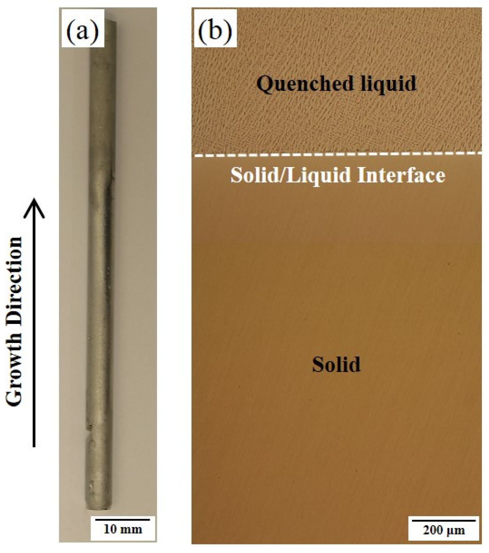
Figure 2.
Schematic diagram of solidification and undercooling occurring in front of the solid/liquid interface. The enrichment of high Tm and high k elements increase the constitutional undercooling () and thermal undercooling (), respectively. Both and increase the driving force of nucleation.
Figure 2.
Schematic diagram of solidification and undercooling occurring in front of the solid/liquid interface. The enrichment of high Tm and high k elements increase the constitutional undercooling () and thermal undercooling (), respectively. Both and increase the driving force of nucleation.
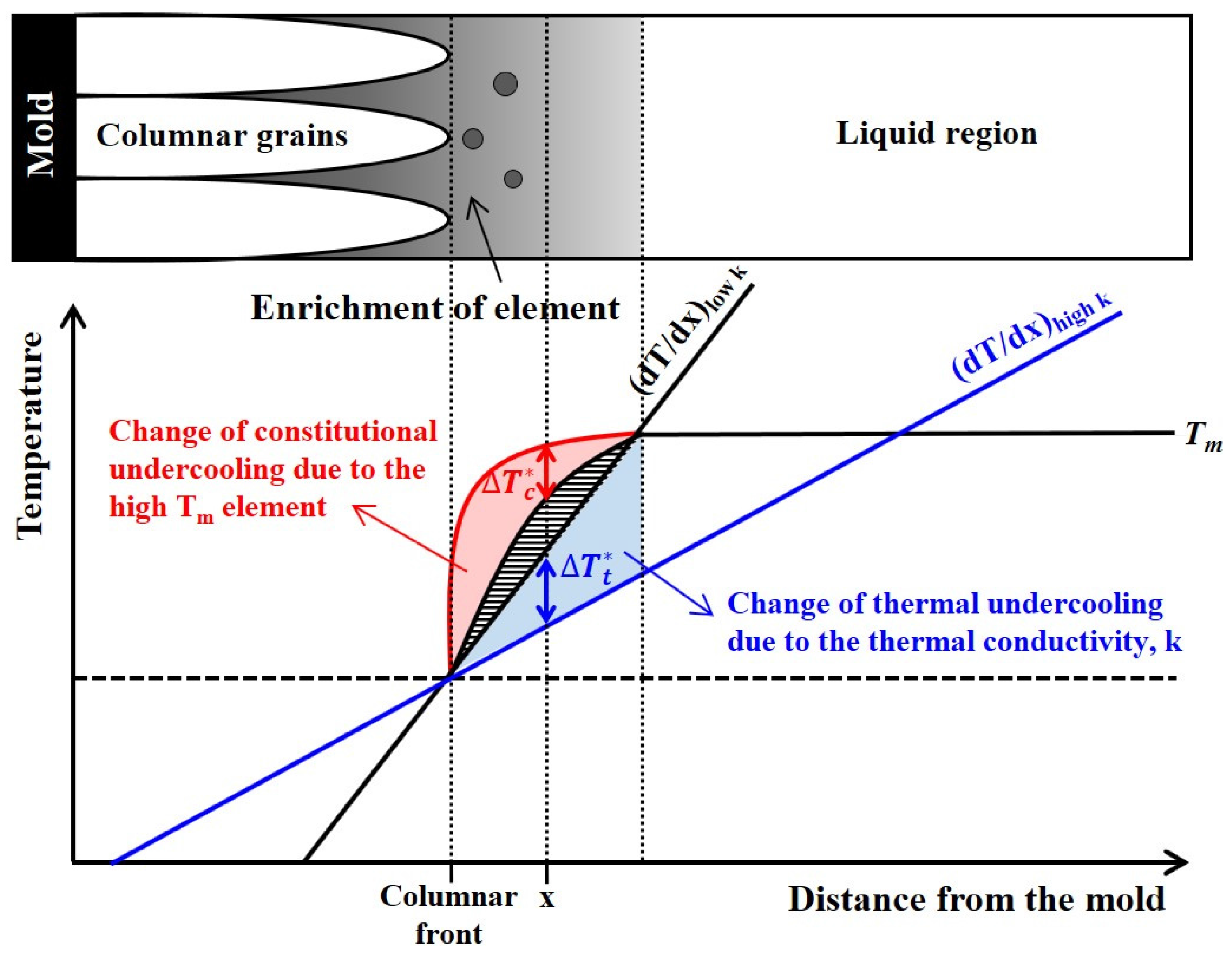
Figure 3.
(a) XRD profiles of newly designed HEAs; Images of the macroscopic grains of (b) Cantor; (c) V5; (d) V10; and (e) V15 alloys. All HEAs consisted of fcc single phase. The area of the equiaxed zone increases with increased concentration of V.
Figure 3.
(a) XRD profiles of newly designed HEAs; Images of the macroscopic grains of (b) Cantor; (c) V5; (d) V10; and (e) V15 alloys. All HEAs consisted of fcc single phase. The area of the equiaxed zone increases with increased concentration of V.
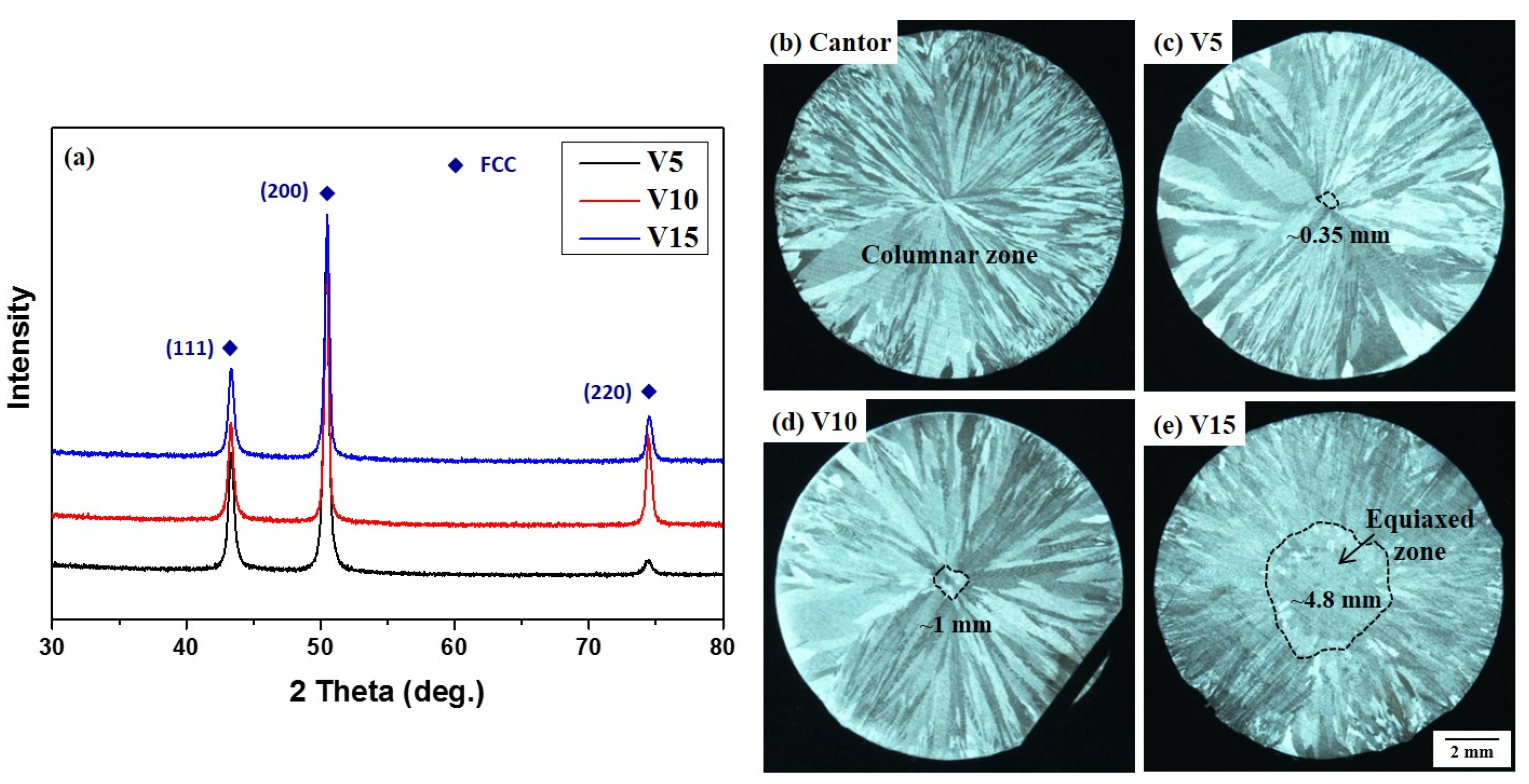
Figure 4.
Macrostructures of the (a) Cantor alloy and (b) V15 HEAs. Tensile specimens were prepared at the center of each material, indicated by the red dotted line, along the three different loading directions plotted in Figure 4b. The x-axis is parallel to the columnar structure.
Figure 4.
Macrostructures of the (a) Cantor alloy and (b) V15 HEAs. Tensile specimens were prepared at the center of each material, indicated by the red dotted line, along the three different loading directions plotted in Figure 4b. The x-axis is parallel to the columnar structure.

Figure 5.
Tensile properties along three different loading directions of the (a) Cantor and (b) V15 HEAs. (c) Anisotropy indices (Ii) for each tensile property of both HEAs. Ii = (standard deviation of ix, iy, and iz)/(average of ix, iy, and iz) × 100, where i = YS, TS, and El. and x, y, and z are the loading directions.


Table 1.
Chemical compositions and partition coefficient (ke) observed at the solid/liquid interface region of HEAs (at %).
Table 1.
Chemical compositions and partition coefficient (ke) observed at the solid/liquid interface region of HEAs (at %).
| Alloys | Co. | Cr | Fe | Mn | Ni | |
|---|---|---|---|---|---|---|
| Cantor | Solid | 22.76 | 19.39 | 20.46 | 16.26 | 20.73 |
| Liquid | 19.75 | 17.09 | 16.5 | 24.64 | 21.34 | |
| ke | 1.15 | 1.13 | 1.24 | 0.66 | 0.97 | |
Table 2.
Melting temperature (Tm) and thermal conductivity (k) of chemical elements.
| Alloys | Co. | Cr | Fe | Mn | Ni | V |
|---|---|---|---|---|---|---|
| Melting temperature (°C) | 1495 | 1857 | 1535 | 1244 | 1453 | 1890 |
| Thermal conductivity (Wm−1·K−1) | 100 | 93.7 | 80.2 | 7.8 | 90.7 | 30.7 |
Table 3.
Chemical compositions (at %) and entropy, enthalpy, atomic size difference, and valence electron concentration of HEAs used in this work.
Table 3.
Chemical compositions (at %) and entropy, enthalpy, atomic size difference, and valence electron concentration of HEAs used in this work.
| Alloys | Co. | Cr | Fe | Mn | Ni | V | ΔSmix (J·K−1·mol−1) | ΔHmix (kJ·mol−1) | δ (%) | VEC |
|---|---|---|---|---|---|---|---|---|---|---|
| Cantor | 20 | 20 | 20 | 20 | 20 | - | 13.38 | −4.16 | 3.27 | 8 |
| V5 | 20 | 15 | 20 | 15 | 25 | 5 | 12.76 | −4.95 | 3.06 | 8.1 |
| V10 | 10 | 10 | 30 | 10 | 12.18 | −7.12 | 2.82 | 8.2 | ||
| V15 | 5 | 10 | 30 | 15 | 11.51 | −8.46 | 2.94 | 8.15 |
Table 4.
Tensile properties of Cantor and V15 HEAs.
| Alloys | Loading Direction | Yield Strength (MPa) | Tensile Strength (MPa) | Elongation (%) |
|---|---|---|---|---|
| Cantor | x | 194 ± 5.4 | 409 ± 2.5 | 65.6 ± 0.1 |
| y | 168 ± 4.4 | 435 ± 4.5 | 78.7 ± 1.7 | |
| z | 188 ± 4.0 | 455 ± 11.2 | 72.2 ± 2.6 | |
| Anisotropy Index | 7.43 | 5.33 | 9.08 | |
| V15 | x | 246 ± 2.5 | 479 ± 0.6 | 72.8 ± 1.1 |
| y | 255 ± 3.8 | 496 ± 8.6 | 74.3 ± 3.5 | |
| z | 264 ± 9.9 | 525 ± 18.8 | 78.7 ± 2.5 | |
| Anisotropy Index | 3.53 | 4.65 | 4.07 |
© 2018 by the authors. Licensee MDPI, Basel, Switzerland. This article is an open access article distributed under the terms and conditions of the Creative Commons Attribution (CC BY) license (http://creativecommons.org/licenses/by/4.0/).
Share and Cite
MDPI and ACS Style
Kang, M.; Won, J.W.; Lim, K.R.; Kwon, H.-J.; Seo, S.M.; Na, Y.S. Compositional Approach to Designing Fcc High-Entropy Alloys that Have an Enlarged Equiaxed Zone. Metals 2018, 8, 54. https://doi.org/10.3390/met8010054
AMA Style
Kang M, Won JW, Lim KR, Kwon H-J, Seo SM, Na YS. Compositional Approach to Designing Fcc High-Entropy Alloys that Have an Enlarged Equiaxed Zone. Metals. 2018; 8(1):54. https://doi.org/10.3390/met8010054
Chicago/Turabian StyleKang, Minju, Jong Woo Won, Ka Ram Lim, Heoun-Jun Kwon, Seong Moon Seo, and Young Sang Na. 2018. "Compositional Approach to Designing Fcc High-Entropy Alloys that Have an Enlarged Equiaxed Zone" Metals 8, no. 1: 54. https://doi.org/10.3390/met8010054
Note that from the first issue of 2016, this journal uses article numbers instead of page numbers. See further details here.