Numerical Simulation of Tensile Behavior of Corroded Aluminum Alloy 2024 T3 Considering the Hydrogen Embrittlement

Laboratory of Technology & Strength of Materials, Department of Mechanical Engineering & Aeronautics, University of Patras, 26500 Patras, Greece
*
Author to whom correspondence should be addressed.
Metals 2018, 8(1), 56; https://doi.org/10.3390/met8010056
Submission received: 31 October 2017
/
Revised: 21 December 2017
/
Accepted: 10 January 2018
/
Published: 15 January 2018
Abstract
:A multi-scale modeling approach for simulating the tensile behavior of the corroded aluminum alloy 2024 T3 was developed, accounting for both the geometrical features of corrosion damage and the effect of corrosion-induced hydrogen embrittlement (HE). The approach combines two Finite Element (FE) models: a model of a three-dimensional Representative Unit Cell (RUC), representing an exfoliated area and its correspondent hydrogen embrittled zone (HEZ), and a model of the tensile specimen. The models lie at the micro- and macro-scales, respectively. The characteristics of the HEZ are determined from measurements of nanoindentation hardness, conducted on pre-corroded specimens. Using the model of the RUC, the local homogenized mechanical behavior of the corroded material is simulated. Then, the behavior of the exfoliated areas is assigned into different areas (elements) of the tensile specimen and final analyses are performed to simulate the tensile behavior of the corroded material. The approach was applied to model specimens after 8, 16 and 24 h exposure periods of the Exfoliation Corrosion (EXCO) test. For validation of the approach, tensile tests were used. The numerical results show that this approach is suitable for accurately simulating the tensile behavior of pre-corroded experimental specimens, accounting for both geometrical features of corrosion damage and corrosion-induced HE.
1. Introduction
Heat treatable aluminum alloys, such as 2024 T3, are widely employed in the aeronautics industry, due to their good specific properties and high damage tolerance, yet they are prone to corrosion damage in chloride environments [1].
Corrosion damage in aeronautical aluminum alloys may appear in the form of pits, intergranular corrosion and exfoliation corrosion [2,3,4]. Only a few concepts were reported, aiming to directly correlate the metallographic features, which characterize corrosion damage of a material to the resulting degradation of its mechanical properties. Such a correlation is not an easy task, as the term “corrosion damage” is in the first place, a qualitative term, which needs to be first related to specific and measurable material features in order to be quantified and, in addition, the evolution of these features follows usually non-linear time functions [5,6,7]. In [8], a correlation between the metallographic features of corrosion damage developed on the magnesium alloy AZ31 and the mechanical properties of the corroded material has been made manageable by using artificial neural networks. This approach has been proven efficient and useful, yet it remains formalistic and rather empirical with limited reference to the underlying mechanisms.
Another approach represents the development of analytical models, aiming to assess the effects of idealized metallographic features, which characterize corrosion damage, e.g., a semi-elliptical pit, a stress field caused by a mechanical load, etc. [9,10,11,12,13,14,15,16,17,18]. In [9], the stress distribution under uniaxial tension loading at semi-elliptical corrosion pits was investigated by developing three-dimensional (3D) pit models with varying pit diameters and pit depths. It was concluded that the pit aspect ratio is the main parameter affecting the value of the stress concentration factor and that any pit formation can cause crack initiation under mechanical loading. In [14], Pidaparti and Patel investigated the evolution of stresses around a single corrosion pit with exposure time, using 3D Finite Element (FE) models. They found that at the beginning, the stresses increase dramatically and after a period of corrosion exposure, they decrease, probably due to crack initiation, caused by the presence of the pit. In the work in [5], a multi-scale modeling approach for simulating the tensile behavior of corroded aluminum alloy 2024 T3 was developed, successfully assessing the effect of pitting and exfoliation corrosion on tensile strength and elongation, to fracture of the corroded material with time, by accounting for the geometrical discontinuities caused by the evolving corrosion damage.
However, a series of studies performed on the 2024 aluminum alloy gave evidence that the corrosion process is also associated to an hydrogen embrittlement (HE) process [3,4,19,20]. The broad consequence of corrosion damage is the degradation of the mechanical performance of the material under both static and fatigue loading [2,3,21,22], with particularly intense diminishing of elongation to fracture being correlated to the presence of a hydrogen embrittled zone (HEZ), e.g., [2,3,4,5,6,23]. The evaluation of the extension of the HEZ in the specimen, and of its local mechanical properties, are not trivial tasks. Traditional methods of diffusion identification, such as Secondary Ion Mass Spectroscopy (SIMS) and Fourier Transform Infrared Spectroscopy (FT-IR) do not readily distinguish corrosion products from atomic hydrogen, and its spatial resolution can be limited [24]. More sophisticated techniques, such as Kelvin Probe Force Microscopy, employed in the works in [24,25,26], was shown to be efficient in the detection of atomic hydrogen in 2024 T3’s lattice, with maximum depth of penetration of the order of 300 μm for longer exposure periods. Other techniques, such as temperature-programmed desorption, employed by Kamoutsi et al. [23], have resulted in the detection of hydrogen trapped during the corrosion process. Scanning electron microscope (SEM) analysis of the fractured surface of Exfoliation Corrosion (EXCO)-corroded tension specimens, as performed in the works in [2,3], allows one to observe the presence of a quasi-cleavage zone under the pits and exfoliated regions, attributed to the presence of hydrogen and varying in extension with the depth of the geometrical corrosion features. In addition, none of these techniques were initially designed to quantify the local mechanical properties of a material within the embrittled zone. Therefore, developed analytical models tend to overlook the effect of corrosion-induced HE, accounting mostly—if not exclusively—for the influence of the metallographic features of corrosion damage, such as pit depth and diameter. To the extent of the authors’ knowledge, no attempts were performed to numerically simulate the combined effects of geometrical features of corrosion damage and corrosion-induced HE on the tensile behavior of a 2024 T3 aluminum alloy.
In this work, a multi-scale modeling approach for simulating the tensile behavior of the corroded aluminum alloy 2024 T3 specimens was developed by accounting for corrosion damage, in terms of both geometrical discontinuities and the HEZ caused by the corrosion process. The approach upgrades the model presented in [5]; the proposed approach integrates two FE models: a three-dimensional model of a Representative Unit Cell (RUC) representing the areas attacked by corrosion (micro-scale) and a model of the entire tensile specimen (macro-scale). The geometry of the RUC is constructed based on a combination of data from a detailed metallographic analysis of corroded specimens obtained by Setsika et al. [2] and the local mechanical properties of the HEZ obtained by exploiting nanoindentation hardness measurements. Nanoindentation hardness tests were exploited to quantify both the depth as well as the local mechanical properties of the HEZ identified in 2024 T3 specimens exposed to EXCO tests. To assess the predictive ability of the introduced modeling approach, the numerical results were validated against tensile tests, conducted on corroded specimens in a previous work [2].
2. The Multi-Scale Approach
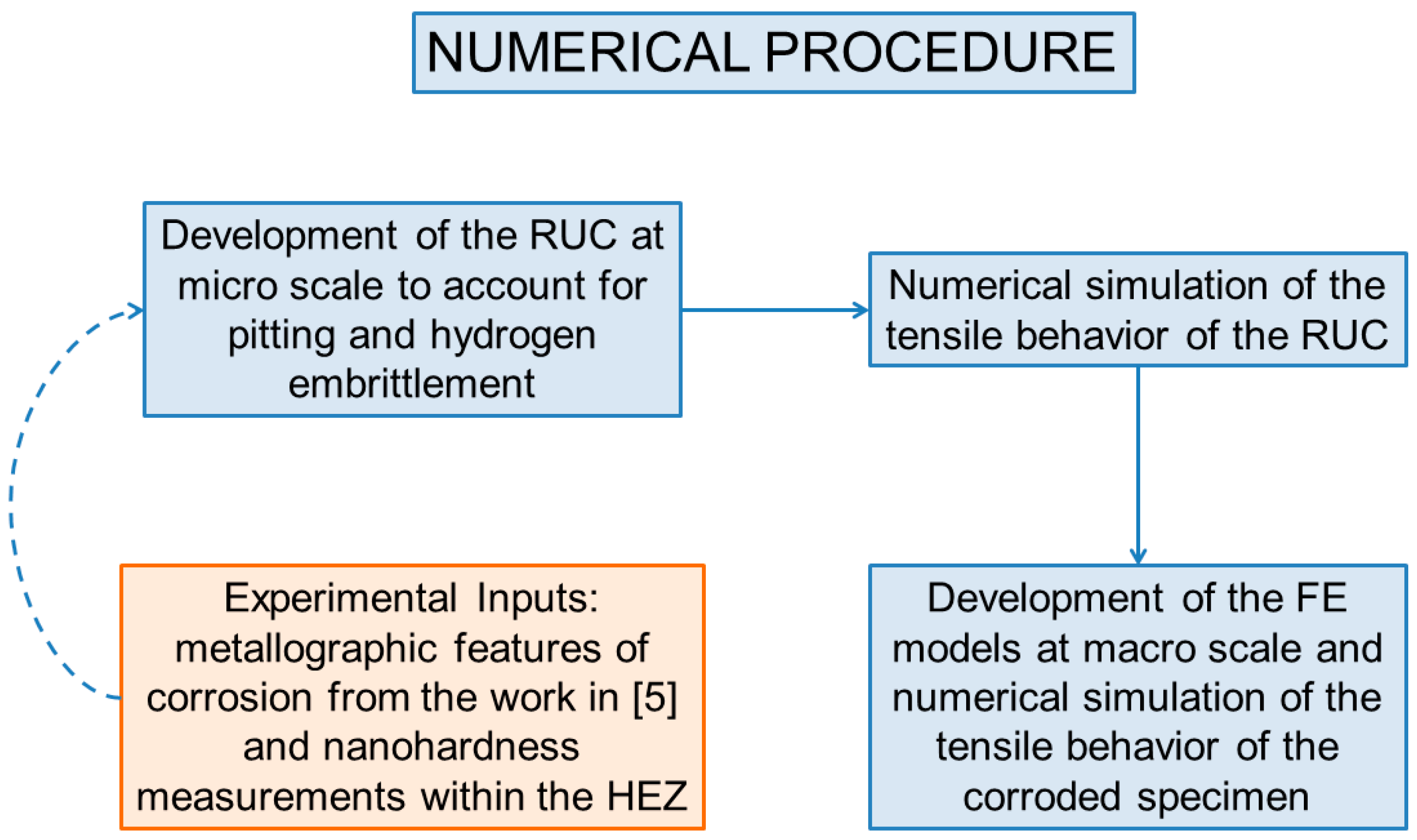
To simulate the tensile behavior of corroded material, a multi scale FE-based modeling approach was developed. This approach is based on the work in [5], which combines two FE models: the FE model of a RUC (micro-scale), representing a single pit or exfoliated area and the FE model of the tensile specimen (macro-scale). The model of the RUC, which is constructed in [5], based on experimental data gathered in the work in [2], was updated in this work, through the insertion of its respective HEZ. The mechanical behavior of the exfoliated areas was simulated and used as an input at specific elements of the specimen’s FE model. The combined experimental-numerical approach is explained by means of the flowchart shown in Figure 1. The quantification of corrosion damage and the establishment of the physical background of the materials’ property degradation serve as the base for the development of the multi-scale modeling approach.
2.1. Basic Considerations
The development of the multi-scale methodology, accounting for the geometrical features of corrosion damage, was based on the work in [5]. The assumptions made in that work are summarized here, for the sake of completeness of the paper:
- For the macro-scale model, a random distribution of exfoliated areas, throughout the whole specimen, is considered. The higher degree of damage observed for the side surface of the specimens, as compared to the degree of damage observed at top surfaces, was also considered.
- The metallographic analysis performed in [2] revealed that the deepest exfoliated areas also have the largest diameter. Based on this observation, it was assumed that the largest and deepest exfoliated areas have the most significant effects on the mechanical properties of the corroded material.
- The shape of the exfoliated areas was irregular. For simplicity reasons, all of them were considered to have the shape of a truncated cone.
- The following assumptions, derived from the evaluation of experimental findings within the HEZ, and considering the simulation capabilities, were taken:
- The observation of a quasi-cleavage transition zone below the intergranular fracture zone, in pre-corroded tensile specimens, in previous works [2,3,21,23], is attributed to the presence of trapped hydrogen in the region under the pit bottom. Also, nanoindentation hardness values are lowest at the initial measurements (0 μm). Therefore, the HEZ was considered to start immediately below the bottom of the pits and exfoliated areas for all cases.
- Following the measurements of nanoindentation hardness after 24 h of exposure, each correspondent numerical HEZ was divided in three parts of equal dimensions and progressively increasing mechanical properties, for all simulated periods.
- Even though the dimensions of the exfoliated areas were considered to differ from top to side surfaces, the dimensions of the HEZ were kept constant for all cases.
2.2. The Representative Unit Cell (Micro-Scale)
2.2.1. Experimental Tests and Findings
For the RUC to be developed, experimental data on both the geometrical metallographic features and HE of the specimen are needed.
The experimental procedure and the results obtained for the geometrical metallographic features of the 2024 T3 material were described in detail in [2] and employed as a base of this work and the work in [5]. In the present section, for the sake of completeness of the paper, only a brief description of this procedure will be given.
To induce corrosion damage, the EXCO test, according to ASTM G34 standard [27], was used for three different periods of exposure, namely 8, 16 and 24 h. Cleaning procedures and evaluation of corrosion damage were performed according to ASTM G01-03 [28]. For the characterization of the geometrical features of corrosion damage, the metallographic features considered were pit depth, pit diameter, pitting density and pit shape. Furthermore, a classification of the pits or the exfoliated areas regarding their depth was performed. To evaluate the corrosion damage effect on the mechanical properties of the alloy, tensile tests were conducted on pre-corroded specimens for all three exposure times. Moreover, SEM fractography was performed on the fracture surfaces of the tensile specimens [2]. The results obtained in [2] showed that corrosion damage starts in the form of pits and evolves to exfoliation corrosion, with increased damage over time. The evolving corrosion damage causes an appreciable decrease in the tensile properties of the material. This degradation increases with increasing corrosion exposure time. It is noticeable that the reduction in the tensile strength properties, namely yield and ultimate tensile strengths, remains moderate, reaching up to 20% of the original values after 24 h of exposure. On the other hand, the decrease in ductility is high and becomes dramatic at higher exposure times, reaching up to 75% of the original values after 24 h of exposure. SEM fractography revealed a quasi-cleavage zone beneath the depth of corrosion attack; which indicates an embrittlement of the material, most probably due to hydrogen diffusion and accumulation [23]. The moderate degradation in yield and ultimate strength may be attributed to the presence of pits or exfoliated areas; yet, the dramatic degradation of tensile ductility should be understood as a consequence of the synergy of the formation of pits and the corrosion induced hydrogen embrittlement (HE).
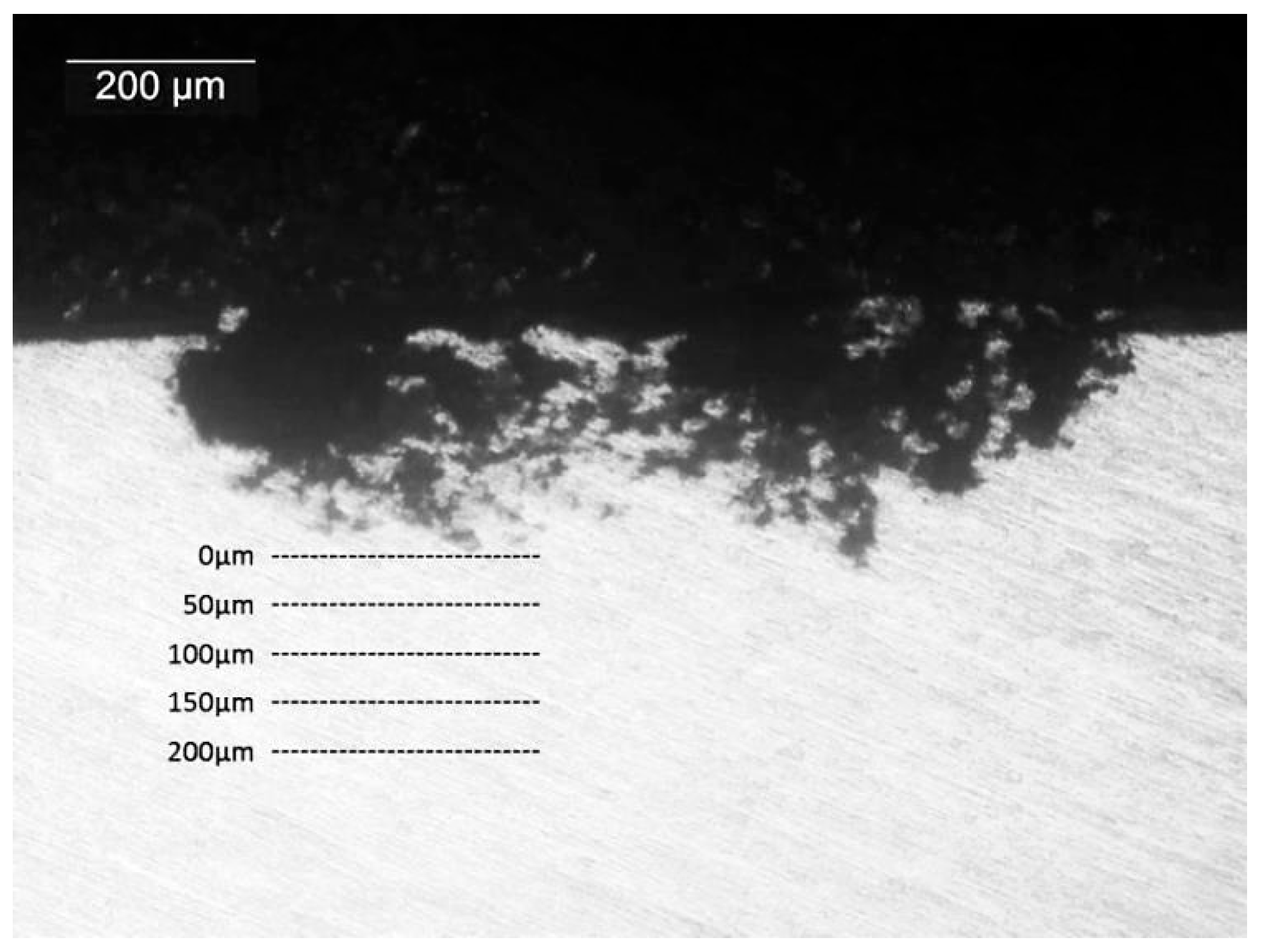
As for the quantification of HE, accounting for both extension and local mechanical properties of the HEZ, measurements of nanoindentation hardness were performed by the Physical Metallurgy Laboratory of the Department of Mechanical Engineering of the Aristotle University of Thessaloniki, utilizing the nanoindentation hardness testing equipment developed locally. A conical indenter with a tip height of 2 nm and a tip roundness width of 52.5 nm was used. Specimens of a bare aluminum alloy 2024 with the T3 thermal treatment in the form of a 1.27 mm nominal thickness sheet, from the same batch as the ones employed in the work in [2], were exposed to EXCO solution for 8, 16 and 24 h. Indentations were carried out using a Berkovich tip on the cross sections of the pre-corroded materials. The indentations were initiated at the bottom of the exfoliated areas and performed sequentially, every 50 μm, as represented schematically in Figure 2. For each depth, an average of 17 measurements were performed.
The indentation’s displacement and load are employed as inputs to calculate the nanoindentation hardness values [29], which show a progressive increase with greater distancing of the pit bottom (Figure 3). Lower values measured near the bottom of the pits can be explained by the presence of atomic hydrogen diffused into the lattice. The presence of these atoms can weaken lattice’s chemical bonds, with a reduction in the cohesive energy of the metallic matrix and decrease in the load carrying capacity of the affected layer, approaching the Hydrogen Enhanced De-cohesion (HEDE) mechanism [30]. The progressive increase can happen due to a limited capacity of atomic hydrogen to diffuse into the lattice, accumulating in higher concentrations within stress fields, such as the one generated at the bottom of the pit [29]. These stress fields were observed in the works of [25,26], where corrosion-induced hydrogen accumulated within the vicinities of high-stress regions, such as grain boundaries and pits, through the employment of Kelvin Probe Force Microscopy and Secondary Ion Mass Spectrometry. With distancing of the affected layer, and approaching the characteristics of the raw material, load carrying capacity is restored and the maximum depth of penetration decreases, leading to increased nanoindentation hardness values. However, the HEDE mechanism alone does not seem sufficient to explain all the effects of HE observed in previous works, such as the presence of a quasi-cleavage zone in tensile fracture surfaces or the decrease in strain of corroded specimens [2,3,4,5,6,21,23]. Most likely, a combination of different mechanisms is responsible for these results, with the need of more experimental observations to fully characterize the main acting mechanism.
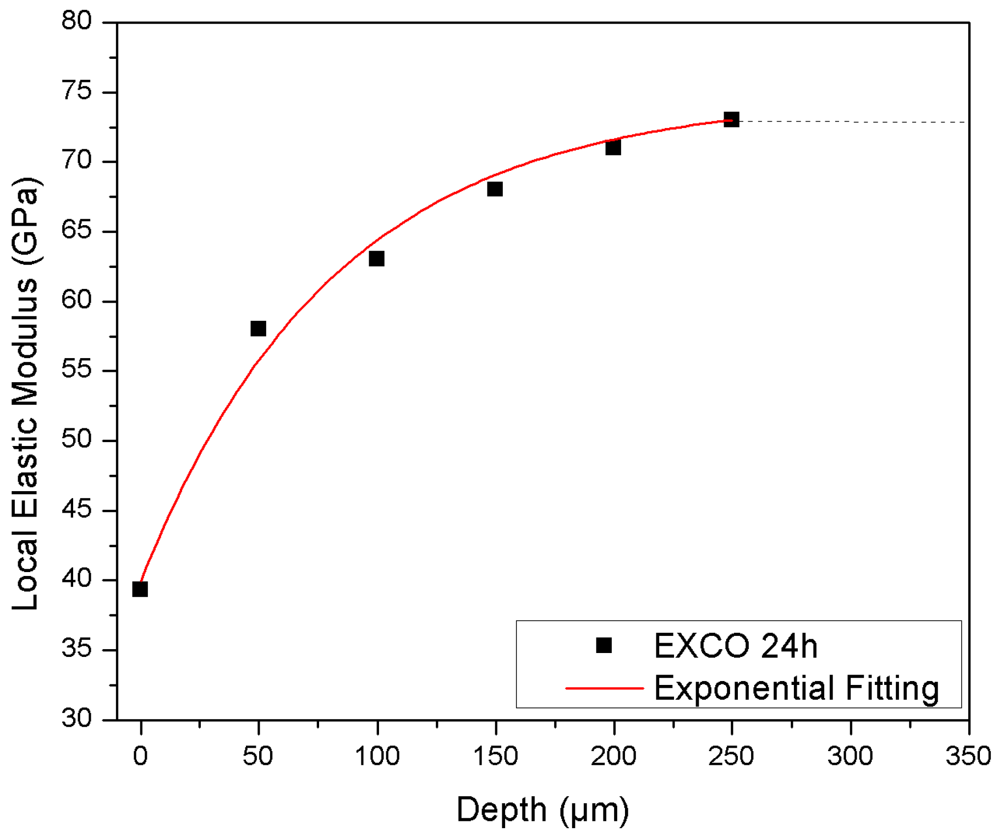
The local elastic modulus is calculated at each measured depth from the nanoindentation hardness measurements within the HEZ of the specimens, utilizing the “FANOS” algorithm [31]. The evolution of this property accompanies the progressive increases shown in Figure 3. The trend, presented by the calculated results of local elastic modulus for the 24 h exposure period, obeys a Stirling exponential fitting (Equation (1)), in which a, b and k are empirical constants, x represents the depth from the bottom of the pit and y represents the local elastic modulus. The resultant exponential fitting is shown in Figure 4, with an adjusted coefficient of determination (R2) of 99%. These values were employed as inputs for the material properties of the HEZ in the numerical approach, which will be detailed in an upcoming section.
For the modeling effort, the extent of the HEZ for different periods of exposure in EXCO solution has been considered to be analogous to the extent of the quasi-cleavage zones observed on the fractured surfaces of corroded specimens in the work in [2]. In this way, the depth of HEZs after 8 h of EXCO exposure would be of the order of 100 μm, observed on the side surfaces of the specimens, and, after 16 h, of the order of 150 μm, observed for all corroded surfaces.
In this way, an initial approach for the estimation of the evolution with time of local mechanical properties within the HEZ in specimens exposed to EXCO solution can be assessed through the employment of the Stirling exponential fitting. By inserting the initial and final values of both depth from the bottom of the pit (x0 and xf) and local elastic modulus (y0 and yf) in Equation (1), the variation of the local elastic modulus can be estimated throughout the HEZ.
The initial values of nanoindentation hardness measured at the bottom of the pits (0 μm) and the calculated local elastic modulus for periods of 8 and 16 h of exposure are presented in Table 1. The values are in accordance with the initial value observed for a 24 h exposure period.
The data employed as inputs for the estimations of the exponential evolution for the local elastic modulus after 8 and 16 h of exposure are shown in Table 2. A final stabilization value for the elastic modulus of 73 GPa, as presented by the uncorroded material, was set at a constant depth of 250 μm from the bottom of the pits. These values were employed as inputs for the material properties of the HEZ in the numerical approach, which will be detailed in an upcoming section.
2.2.2. Geometry and Finite Element Model
A schematic representation of the RUC is displayed in Figure 5. It comprises a 3D cube with an embedded exfoliated area and its respective HEZ. The geometrical features of exfoliation corrosion were considered, as in the work in [5] for 24 h of exposure in EXCO solution. In both top and side surfaces, the external width (equal to the length) and depth of the RUC (w and t respectively) are constant and equal to the deepest and largest pit or exfoliated area observed in the specimen, which is located at its side. The exfoliated areas, located at the top surface, were modeled by their mean geometrical values. A summary of the external dimensions of the RUC and the dimensions of the exfoliated areas for different geometrical features of corrosion are given in Table 3 and Table 4.
The HEZ was considered to start immediately under the bottom of the pits and exfoliated areas. Three sections of equal dimensions, covering the entire width and length of the RUCs, starting immediately under the truncated cone, were selected and new material properties assigned to each of them. This approach aims to simulate the variation of local mechanical properties with depth, according to the respective values obtained by nanoindentation hardness.
The materials employed for the simulation of the HEZs were defined through the exploitation of nanoindentation hardness values into bilinear stress strain curves, established by values of yield stress and ultimate tensile stress. From the nanoindentation hardness tests, the local values of yield stresses were estimated at each depth. These calculations were based on the linear relations presented by values of nanoindentation hardness and Vickers hardness, and, in turn, by Vickers hardness and yield stresses [32]. For an initial approximation effort, the linear constants were calculated based on the relationships presented by the uncorroded material. These constants are shown in Equations (2) and (3), in which HV accounts for the Vickers hardness, HM accounts for the nanoindentation hardness value and σy accounts for the yield stress. The use of linear correlations to estimate the bilinear curves for each material section is useful and simple; however, to improve their accuracy, experimental validations are also necessary. These will be presented in an upcoming work.
Ultimate tensile stresses were calculated by employing constant strain-hardening values. After the realization of a convergence study, which observed which value better fits the trend observed at the tensile tests of the uncorroded material, encompassing values that varied from 1.15 to 1.4, the constant value of 1.2 was chosen. Strain values at the HEZs were considered to remain constant and equal to the ones presented by the uncorroded material. The stress-strain curve of the uncorroded material and the calculated bilinear curves of each HEZ material are depicted in Figure 6.
The RUCs were modeled using the ANSYS SOLID187 element [33]. This is a higher order 3D, 10-node element, well suited to modeling irregular meshes. Each material of the HEZ was defined using ANSYS Bilinear Kinematic Hardening material model, while the non-linear behavior of the core material of the RUC was simulated using ANSYS Multilinear Kinematic Hardening material model, which are suitable for simulating metal plasticity behavior [33]. These material models were chosen, given the authors’ interest in simulating the experimentally-observed diminishment in elongation to fracture of pre-corroded specimens, attributed to the presence of an HEZ. The stress-strain data for the uncorroded material model were derived from the experimental tensile stress-strain curve of the reference material. Core material properties were applied at the region around the pit, based on the observations in the work in [23], in which the mechanical removal of the geometrical features of corrosion was not sufficient to restore the tensile properties of the material to its original values; this was attributed to the presence of an HEZ located below the region affected by pitting and intergranular corrosion. In this way, it was considered in this work that the mechanical properties of the HEZ are restricted to sub-pitting regions. The RUC was loaded in uniaxial tension through the application of an incremental displacement. In parallel, periodic boundary conditions were applied, to derive the homogenized tensile behavior of the RUC, employing the maximal plastic strain value as a boundary condition at each loading step. A representative image of the typical FE mesh and selected materials employed in the micro-scale analysis is shown in Figure 7.
2.2.3. Simulation of the Mechanical Behavior of the Representative Unit Cells
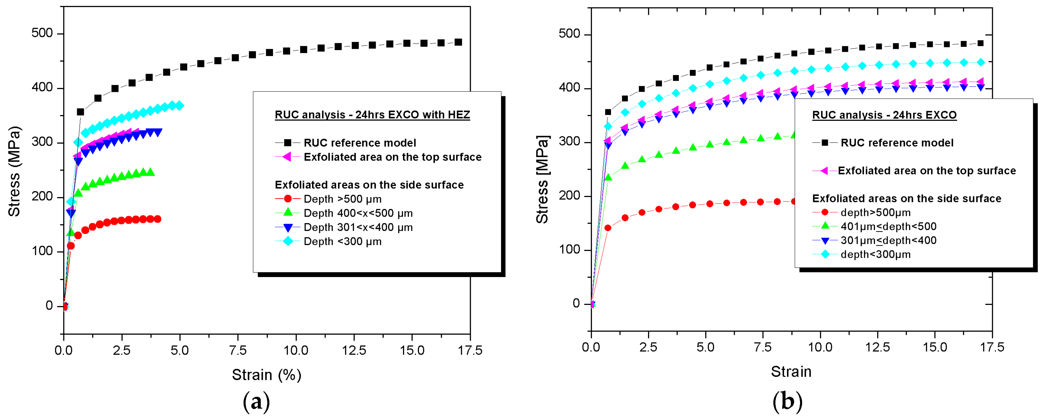
Using the FE model, the degraded homogenized mechanical behavior of the RUCs was simulated for the cases listed in Table 3 and Table 4, with the addition of each respective HEZ. Figure 8 presents the stress-strain curves, resulting from numerical simulations of the RUCs, considering the exfoliated areas on the top and side surfaces, depicted representatively for the case of 24 h of EXCO exposure.
The insertion of corrosion damage, accounting for both the geometrical features of the pits (Table 3 and Table 4) and layers of different material properties representing the HEZs (Figure 6), is represented in Figure 8a. It leads to a decrease in yield stress and ultimate tensile stress, when compared to the RUC’s reference model (uncorroded). Such decreases are analogous to the depth of the exfoliated regions.
The model of the RUC developed in [5], accounting exclusively for the geometrical features of corrosion damage and depicted in Figure 8b, could successfully simulate the decreases in yield and ultimate tensile strengths observed experimentally, but did not represent the accompanying dramatic reduction in elongation to fracture. The insertion of the mechanical properties of the HEZ accounting for the fracture criterion observed for the corroded material in the work in [5], however, such reduction could be observed also in the numerical model, as shown in Figure 8a. For the cases of 8 and 16 h of exposure, the same observations could be traced.
Experimentally, this was shown in [23], where the mechanical removal of the corrosion layer, and therefore, of the geometrical features of corrosion damage, was followed by heating of the material at 495 °C, which removes the trapped hydrogen and fully restores both the yield strength and elongation to fracture to the reference values.
2.3. The Tension Specimen (Macro-Scale)
In order to simulate the tensile behavior of the corroded aluminum material, the same procedure as that followed in [5] was applied. A brief description will be given in the present section for the sake of completeness of the paper.
2.3.1. Geometry and Finite Element Model
The tension specimen described in the ISO 6892-01 standard was modeled. Considering the symmetry of the specimen and loading, a section of a quarter of the specimen was modeled. To model the specimen, the ANSYS 3D SOLID185 [33] element, a 3D 8-node element, was used. The non-linear tensile behavior of the core material of the specimen was specified using the ANSYS Multilinear Kinematic Hardening material model [33], based on the experimental tensile stress-strain curve of the reference material. Following the mesh optimization study performed in [5], the denser mesh employed in that work was also used in this work, which accounts for 110,000 elements. The tensile load was modeled through the application of an incremental axial displacement at the edge of the specimen.
2.3.2. Simulation of Corrosion Damage
The process for introducing exfoliated areas into the specimen’s FE model is equal to the one employed in [5] and it is schematically described in Figure 9. It involves the following assumptions:
- Corrosion damage is modeled by assigning the mechanical behavior of the RUCs with their respective HEZs to specific sets of elements of the specimen.
- The number of degraded sets of elements is extracted from the pit distributions presented in [2]. The groups of degraded elements are randomly placed in the specimen, according to the pit density observed in the cited work after each corrosion period.
- The volume of each group of elements is equal to the volume of the respective RUC model for each case.
- The depth of each group is equal to the depth t of the respective RUC for each case.
The flowchart depicted in Figure 10 represents the sequence followed in this work to introduce corrosion damage into the specimens’ FE models, from the definition of the RUCs until the numerical simulation of the tension specimen. It starts with the insertion of corrosion damage in the RUC, as explained in Section 2.2. The obtained stress-strain curves of each simulated RUC are then defined as the material properties of a specific set of elements, volumetrically equal to their respective RUC. This set of elements now represents the local corrosion damage, which accounts for both the geometrical features of corrosion damage and HE. The volumes of different material properties are then inserted throughout the tension specimen, according to the random distribution and density of pits and exfoliated areas encountered after each exposure period, as observed in [2].
To predict the tensile strength and fracture strain of the corroded specimen, the method of progressive damage modeling was applied. Using the maximum strain failure criterion, strains at the elements were checked and when fracture was predicted, their Young’s modulus was abruptly degraded to a very small value to prevent them from carrying load. This characteristic was employed, aiming to diminish the necessary computational time at each load step, which would be increased with the use of progressive deterioration of the material. The failure criterion was considered to be the critical local strain of the 24 h EXCO corroded specimen, measured in [5] using the GOM Aramis optical device (Patras, Achaia, Greece). The critical local strain value was found to be equal to 13%.
3. Numerical Results
Using the multi-scale modeling approach, the effect of corrosion damage on the tensile properties of corroded aluminum alloy 2024 T3 can be directly predicted, accounting for geometrical discontinuities (pits and exfoliated areas) and HE, as described in Section 2.3.
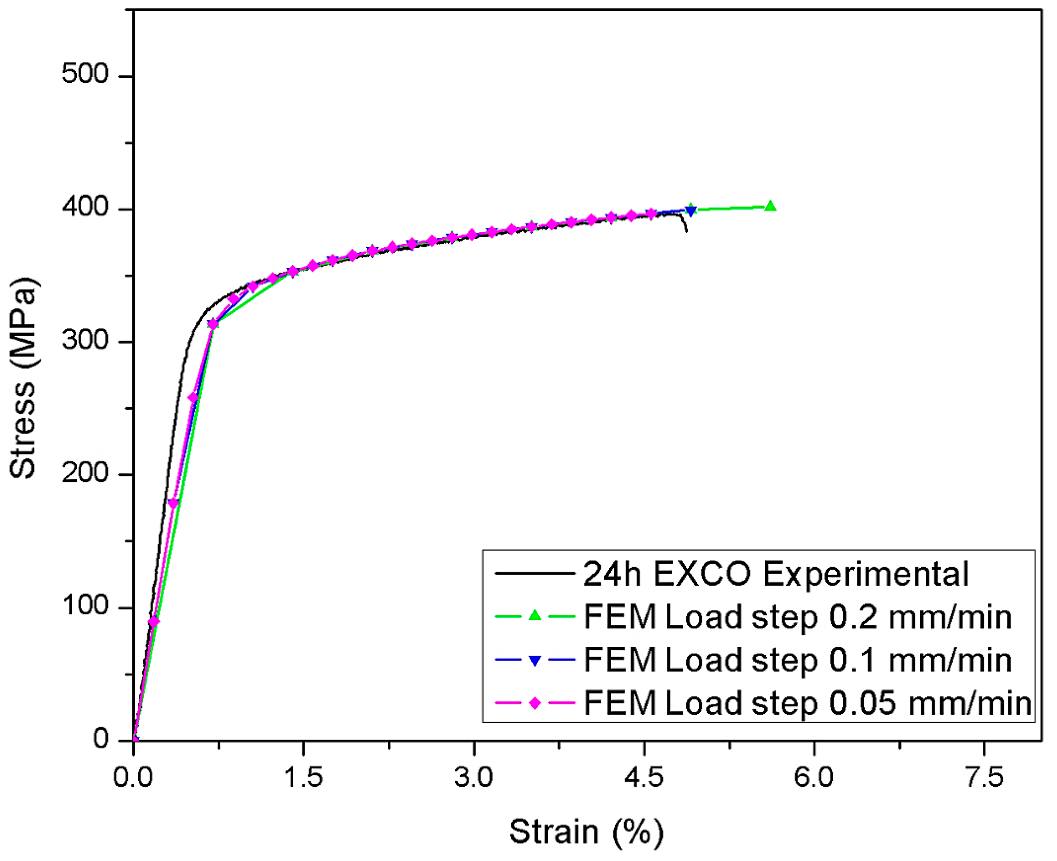
Considering that the tensile load was modeled through the application of an incremental axial displacement at the edge of the specimen, a convergence study was performed regarding the effect of the reduction of the considered displacements, or loading steps. The study was performed utilizing data derived from the 24 h exposure period and showed that smaller incremental axial displacement steps performed more accurately than the original values employed by Setsika [5]. The original value presents, therefore, an underestimation of the effect of the HEZ on the diminishing elongation to fracture of the material. However, the use of the smallest displacement steps employed in the present study (0.5 mm/min) lead to an increase in the required computational time to complete the simulation and an overestimation of the effect of the HEZ on the diminishing elongation to fracture of the material, thus making the use of 0.1 mm/min a reasonable choice for the following comparison results. In Figure 10 the results of the convergence study are presented. The deviation between the numerical and experimental Young’s moduli observed in Figure 10 and the forthcoming figures is due to the damage model used and to the adopted load step. As shown, the decrease in the applied load step improves the correlation between the numerical and experimental Young’s moduli. However, a better correlation could not be achieved, due to the significant increase in the computational effort.
In addition, the authors have performed several analyses with different random placements of the elements in the model of the specimen. The difference compared to the predicted numerical curves was found to be very small. Therefore, it is concluded that there is no effect of the random placement of elements.
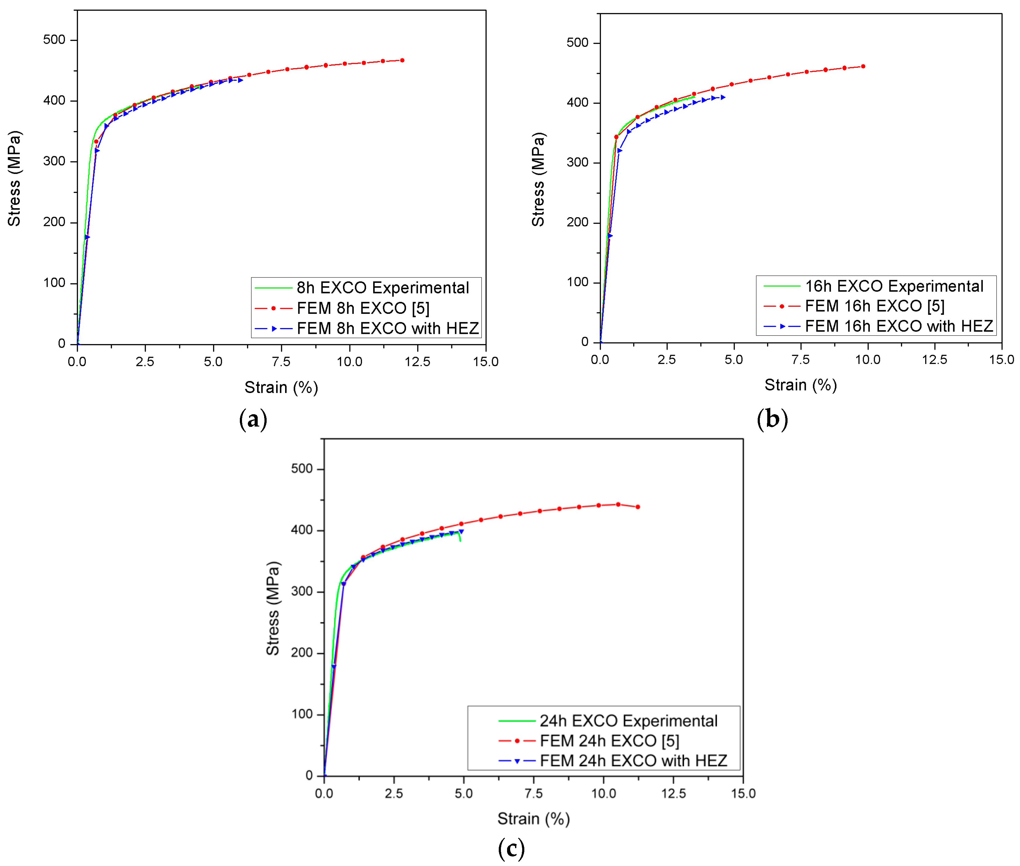
In Figure 11, the predicted stress-strain curve, derived from the numerical analysis of the updated models, accounting for the presence of the HEZs, is compared with the experimental curve of the pre-corroded specimens, for 8, 16 and 24 h in EXCO solution. Also, the predicted curves obtained by Setsika [5], accounting only for the effect of geometrical features of corrosion damage, are displayed for comparison.
In the work in [5] the significant effect of HE on elongation to fracture of the specimens became evident. Regarding the yield strength, it was shown that by considering the corrosion damage, only in the form of pits or exfoliation, the numerical and the experimental results correlate well. It was concluded that the damage in the form of pits or exfoliation leads to deterioration in the yield strength, due to a decrease in the load bearing capacity of the corroded layer. Moreover, the geometrical features of corrosion damage act as stress raisers, thus leading to stress concentration and as a result of the degradation of the yield strength [5,23].
The comparison between the numerical and experimental curves in Figure 11 reveals that the inclusion of the local mechanical properties of the HEZ in the numerical models, along with the geometrical features of corrosion damage, made the simulation of tensile behavior, when compared to the results of the experimental specimens for all cases, manageable, accounting also for the reduction in elongation to fracture. This finding is a clear indication of the significant effect of HE in the elongation to fracture of the material. On the other hand, it is worth noticing that a careful evaluation of the stress-strain curves reveals that the HE plays a role also, to a much smaller extent, in the yield and ultimate tensile strengths, as it accelerates local fracture. These observations are possible, even for an 8 h exposure period, where the main damage mechanism is the formation of pits, whereas for over 16 h of corrosion exposure, it is the exfoliation [2].
The accuracy of the results for elongation to fracture is highly dependent on the accuracy of the nanoindentation hardness measurements, as can be noticed through the comparison of the results in Figure 11. The mechanical properties of the HEZ in the 8 and 16 h analyses were calculated based on the extent of the quasi-cleavage zones, with the use of a large amount of approximation and simplification, causing the accuracy of the resultant numerical curves shown in Figure 11a,b to be smaller than the results obtained, with the use of an experimentally derived curve, as employed in the numerical simulation of the 24 h case (Figure 11c).
Larger discrepancies between the experimental and numerical results can be observed for the case of 16 h of exposure (Figure 11b). This exposure period was characterized in the work in [2] as a transitional period from pitting to exfoliation corrosion, presenting a high variation in depth, diameter and density of the geometrical features of corrosion damage. In this way, the insertion of a HEZ with constant depth, independent of the pit geometry, may have overrated its effect on the mechanical properties of the macro model.
For all cases, a discrepancy can be observed between the experimental and numerical values of Young’s modulus. This can be explained by the simplifications performed in the material models of the HEZ, simulated using the Bilinear Kinematic Hardening material model. The use of a Multilinear Kinematic Hardening material model, accounting for more specific data within the elastic-plastic transition zone, can approximate the numerical from the experimental values and is the object of a future study.
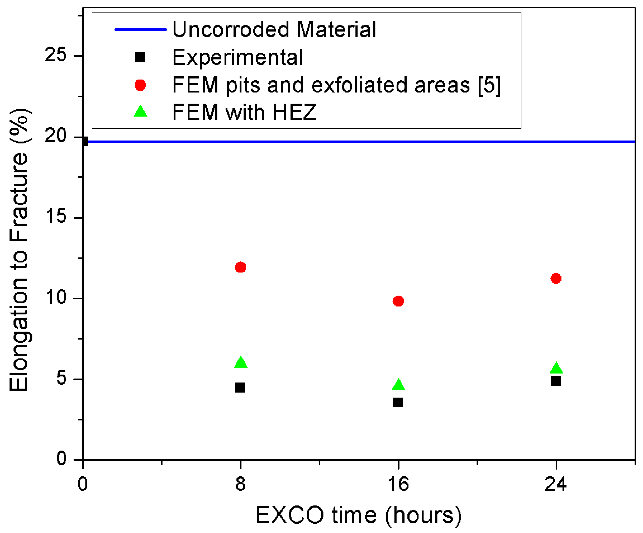
The reduction in elongation to fracture, attributed in previous works [3,23] to the presence of a hydrogen embrittled zone, is also predicted with the employment of the method described in this work and shown in Figure 12. It is important to note that in [5], the reduction in elongation to fracture could not be fully simulated, even though the model predicted a significant effect of pits and exfoliated areas on this property, allowing the estimation of reductions to be 39.49% for 8 h of exposure, 50.15% for 16 h and 43.05% for 24 h of exposure. The insertion of degraded local mechanical properties of the hydrogen embrittled zone is sufficient to simulate the reduction in elongation to fracture observed experimentally, with reductions of 69.75%, 76.85% and 71.52%, for 8, 16 and 24 h, respectively. The observed differences between experimental and numerical results can be related to both the performed simplifications to determine the material properties of the HEZ and the hypothesis for the homogenous extent of the HEZ employed in the present simulations.
4. Conclusions
A multi–scale modeling approach for simulating the tensile behavior of the corroded aluminum alloy 2024 T3 was developed, accounting for both the geometrical features of corrosion damage and the effect of corrosion-induced HE. The approach combines two FE models: a model of a three-dimensional Representative Unit Cell (RUC), representing an exfoliated area and its correspondent hydrogen embrittled zone (HEZ), and a model of the tensile specimen. The models lie at the micro- and macro-scales, respectively. The characteristics of the HEZ are determined from measurements of nanoindentation hardness, conducted on pre-corroded specimens. Using the model of the RUC, the local homogenized mechanical behavior of the corroded material is simulated. Then, the behavior of the exfoliated areas is assigned into different volumes (sets of elements) of the tensile specimen and final analyses are performed to simulate the tensile behavior of the corroded material. The approach was applied to model specimens after 8, 16 and 24 h exposure periods to the Exfoliation Corrosion (EXCO) test. For the validation of the approach, tensile tests were used. The following conclusions can be made from this work:
- The employment of a multi-scale approach is suitable for the simulation of the tensile behavior of 2024 T3 aluminum alloy pre-corroded specimens, accounting for both the metallographic features of corrosion damage and the effect of HE on diminishing local mechanical properties.
- The insertion of the degraded properties of the hydrogen embrittled zone into the RUC, upgrading the existing model which accounted only for geometrical features of corrosion damage, is sufficient to simulate the experimentally observed diminishing elongation to fracture, given the simplifications performed in determining the HEZ’s mechanical properties.
- The model could be applied for the simulation of the mechanical behavior of any corroded structural part in which there is the possibility of occurrence of HE (e.g., a mechanically-fastened panel exposed to marine or industrial environments) made from the aluminum 2024 T3 alloy.
The techniques used in this work represent an initial effort to quantify and numerically simulate corrosion damage, accounting for a more holistic interpretation of the complex and convoluting mechanisms involved in the corrosion phenomenon. The accuracy of the presented results can be largely improved with the use of more robust experimental observations, such as the employment of real stress-strain curves derived from nanoindentation hardness measurements, instead of the use of bilinear curves. In this way, the resultant values of yield strength would become closer to the ones observed experimentally.
Acknowledgments
The authors gratefully acknowledge Nikolaos Michailidis and his team for their support on the nanoindentation hardness measurements as well as for fruitful discussions and motivating remarks.
Author Contributions
S.G.P. and K.T. devised the project, the main conceptual ideas and proof outline, while M.C.V. worked out the technical details, and performed the numerical analysis for the suggested experiment.
Conflicts of Interest
The authors declare no conflict of interest.
References
- Davis, J.R. Corrosion in Aluminum and Aluminum Alloys; ASM International: Almere, The Netherlands, 1999. [Google Scholar]
- Pantelakis, S.; Setsika, D.; Chamos, A.; Zervaki, A. Corrosion damage evolution of the aircraft aluminum alloy 2024 T3. Int. J. Struct. Integr. 2016, 7, 25–46. [Google Scholar] [CrossRef]
- Petroyiannis, P.V.; Kamoutsi, E.; Kermanidis, A.T.; Pantelakis, S.G.; Bontozoglou, V.; Haidemenopoulos, G.N. Evidence on the corrosion-induced hydrogen embrittlement of the 2024 aluminium alloy. Fatigue Fract. Eng. Mater. Struct. 2005, 28, 565–574. [Google Scholar] [CrossRef]
- Pantelakis, S.G.; Chamos, A.N.; Setsika, D. Tolerable corrosion damage on aircraft aluminum structures: Local cladding patterns. Theor. Appl. Fract. Mech. 2012, 58, 55–64. [Google Scholar] [CrossRef]
- Setsika, D.; Tserpes, K.; Pantelakis, S. Numerical simulation of tensile behavior of corroded aluminum alloy 2024 T3. Int. J. Struct. Integr. 2015, 6, 451–467. [Google Scholar] [CrossRef]
- Vasco, M.C.; Chamos, A.N.; Pantelakis, S.G. Effect of environment’s aggressiveness on the corrosion damage evolution and mechanical behavior of AA 2024-T3. Fatigue Fract. Eng. Mater. Struct. 2017, 40, 1551–1561. [Google Scholar] [CrossRef]
- Ishihara, S.; Saka, S.; Nan, Z.Y.; Goshima, T.; Sunada, S. Prediction of corrosion fatigue lives of aluminium alloy on the basis of corrosion pit growth law. Fatigue Fract. Eng. Mater. Struct. 2006, 29, 472–480. [Google Scholar] [CrossRef]
- Kappatos, V.; Chamos, A.N.; Pantelakis, S.G. Assessment of the effect of existing corrosion on the tensile behaviour of magnesium alloy AZ31 using neural networks. Mater. Des. 2010, 31, 336–342. [Google Scholar] [CrossRef]
- Cerit, M.; Genel, K.; Eksi, S. Numerical investigation on stress concentration of corrosion pit. Eng. Fail. Anal. 2009, 16, 2467–2472. [Google Scholar] [CrossRef]
- Cerit, M. Numerical investigation on torsional stress concentration factor at the semi elliptical corrosion pit. Corros. Sci. 2013, 67, 225–232. [Google Scholar] [CrossRef]
- Hingorani, R.; Pérez, F.; Sánchez, J.; Fullea, J.; Andrade, C.; Tanner, P. Loss of ductility and strength of reinforcing steel due to pitting corrosion. In Proceedings of the 8th International Conference on Fracture Mechanics of Concrete and Concrete Structures FraMCoS-8, Toledo, Spain, 11–14 March 2013; pp. 2009–2018. [Google Scholar]
- Liao, M.; Bellinger, N.; Komorowski, J. Modeling the effects of prior exfoliation corrosion on fatigue life of aircraft wing skins. Int. J. Fatigue 2003, 25, 1059–1067. [Google Scholar] [CrossRef]
- Pidaparti, R.M.; Rao, A.S. Analysis of pits induced stresses due to metal corrosion. Corros. Sci. 2008, 50, 1932–1938. [Google Scholar] [CrossRef]
- Pidaparti, R.M.; Patel, R.K. Investigation of a single pit/defect evolution during the corrosion process. Corros. Sci. 2010, 52, 3150–3153. [Google Scholar] [CrossRef]
- Rajabipour, A.; Melchers, R.E. A numerical study of damage caused by combined pitting corrosion and axial stress in steel pipes. Corros. Sci. 2013, 76, 292–301. [Google Scholar] [CrossRef]
- Turnbull, A.; Horner, D.A.; Connolly, B.J. Challenges in modelling the evolution of stress corrosion cracks from pits. Eng. Fract. Mech. 2009, 76, 633–640. [Google Scholar] [CrossRef]
- Turnbull, A.; Wright, L.; Crocker, L. New insight into the pit-to-crack transition from finite element analysis of the stress and strain distribution around a corrosion pit. Corros. Sci. 2010, 52, 1492–1498. [Google Scholar] [CrossRef]
- Kermanidis, A.T.; Stamatelos, D.G.; Labeas, G.N.; Pantelakis, S.G. Tensile behaviour of corroded and hydrogen embrittled 2024 T351 aluminum alloy specimen. Theor. Appl. Fract. Mech. 2006, 45, 148–158. [Google Scholar] [CrossRef]
- Kamoutsi, H.; Haidemenopoulos, G.N.; Bontozoglou, V.; Petroyiannis, P.V.; Pantelakis, S.G. Effect of prior deformation and heat treatment on the corrosion-induced hydrogen trapping in aluminium alloy 2024. Corros. Sci. 2014, 80, 139–142. [Google Scholar] [CrossRef]
- Rodopoulos, C.A.; Pantelakis, S.G.; Papadopoulos, M.P. The effect of ultrasonic impact treatment on the fatigue resistance of friction stir welded panels. J. Mater. Eng. Perform. 2009, 18, 1248–1257. [Google Scholar] [CrossRef]
- Petroyiannis, P.V.; Kermanidis, A.T.; Papanikos, P.; Pantelakis, S.G. Corrosion-induced hydrogen embrittlement of 2024 and 6013 aluminum alloys. Theor. Appl. Fract. Mech. 2004, 41, 173–183. [Google Scholar] [CrossRef]
- Pantelakis, S.G.; Daglaras, P.G.; Apostolopoulos, C.A. Tensile and energy density properties of 2024, 6013, 8090 and 2091 aircraft aluminum alloy after corrosion exposure. Theor. Appl. Fract. Mech. 2000, 33, 117–134. [Google Scholar] [CrossRef]
- Kamoutsi, H.; Haidemenopoulos, G.N.; Bontozoglou, V.; Pantelakis, S. Corrosion-induced hydrogen embrittlement in aluminum alloy 2024. Corros. Sci. 2006, 48, 1209–1224. [Google Scholar] [CrossRef]
- Larignon, C.; Alexis, J.; Andrieu, E.; Odemer, G.; Blanc, C. The contribution of hydrogen to the corrosion of 2024 aluminium alloy exposed to thermal and environmental cycling in chloride media. Corros. Sci. 2013, 69, 211–220. [Google Scholar] [CrossRef] [Green Version]
- Larignon, C.; Alexis, J.; Andrieu, E.; Lacroix, L.; Odemer, G.; Blanc, C. Combined Kelvin probe force microscopy and secondary ion mass spectrometry for hydrogen detection in corroded 2024 aluminium alloy. Electrochim. Acta 2013, 110, 484–490. [Google Scholar] [CrossRef] [Green Version]
- Larignon, C.; Alexis, J.; Andrieu, E.; Lacroix, L.; Odemer, G.; Blanc, C. Investigation of Kelvin probe force microscopy efficiency for the detection of hydrogen ingress by cathodic charging in an aluminium alloy. Scr. Mater. 2013, 68, 479–482. [Google Scholar] [CrossRef] [Green Version]
- American Society for Testing and Materials. Standard Test Method for Exfoliation Corrosion Susceptibility in 2XXX and 7XXX Series Aluminum Alloys (EXCO Test) 1. ASTM Int. 2007, 1, 1–8. [Google Scholar] [CrossRef]
- Oliver, W.C.; Pharr, G.M. Measurement of hardness and elastic modulus by instrumented indentation: Advances in understanding and refinements to methodology. J. Mater. Res. 2004, 19, 3–20. [Google Scholar] [CrossRef]
- Barnoush, A.; Vehoff, H. In situ electrochemical nanoindentation: A technique for local examination of hydrogen embrittlement. Corros. Sci. 2008, 50, 259–267. [Google Scholar] [CrossRef]
- Birnbaum, H.K.; Sofronis, P. Hydrogen-enhanced localized plasticity—A mechanism for hydrogen-related fracture. Mater. Sci. Eng. A 1994, 176, 191–202. [Google Scholar] [CrossRef]
- Bouzakis, K.-D.; Michailidis, N. An accurate and fast approach for determining materials stress–strain curves by nanoindentation and its FEM-based simulation. Mater. Charact. 2006, 56, 147–157. [Google Scholar] [CrossRef]
- Sawa, T. Correlation between Nanoindentation Test Result and Vickers Hardness. In Proceedings of the IMEKO 2010 TC3, TC5 and TC22 Conferences, Pattaya, Thailand, 22−25 November 2010. [Google Scholar]
- ANSYS, Inc. Release 11.0 Documentation for ANSYS; ANSYS, Inc.: Canonsburg, PA, USA, 2006. [Google Scholar]
Figure 1.
Flowchart of the combined experimental-numerical approaches. Hydrogen embrittled zone (HEZ); Representative Unit Cell (RUC).
Figure 1.
Flowchart of the combined experimental-numerical approaches. Hydrogen embrittled zone (HEZ); Representative Unit Cell (RUC).

Figure 2.
Placement of the nanoindentation hardness measurements from the bottom of the pit.

Figure 3.
Nanoindentation hardness evolution, per distance, from the pit bottom after 24 h in Exfoliation Corrosion (EXCO) solution.
Figure 3.
Nanoindentation hardness evolution, per distance, from the pit bottom after 24 h in Exfoliation Corrosion (EXCO) solution.
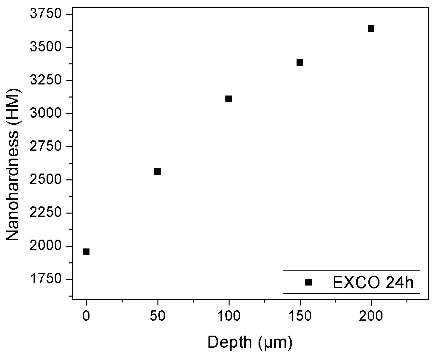
Figure 4.
Evolution of HEZ’s local elastic modulus with depth and exponential fitting of local elastic modulus values, for 24 h exposed specimens.
Figure 4.
Evolution of HEZ’s local elastic modulus with depth and exponential fitting of local elastic modulus values, for 24 h exposed specimens.

Figure 5.
Schematic representation of the Representative Unit Cell (RUC).
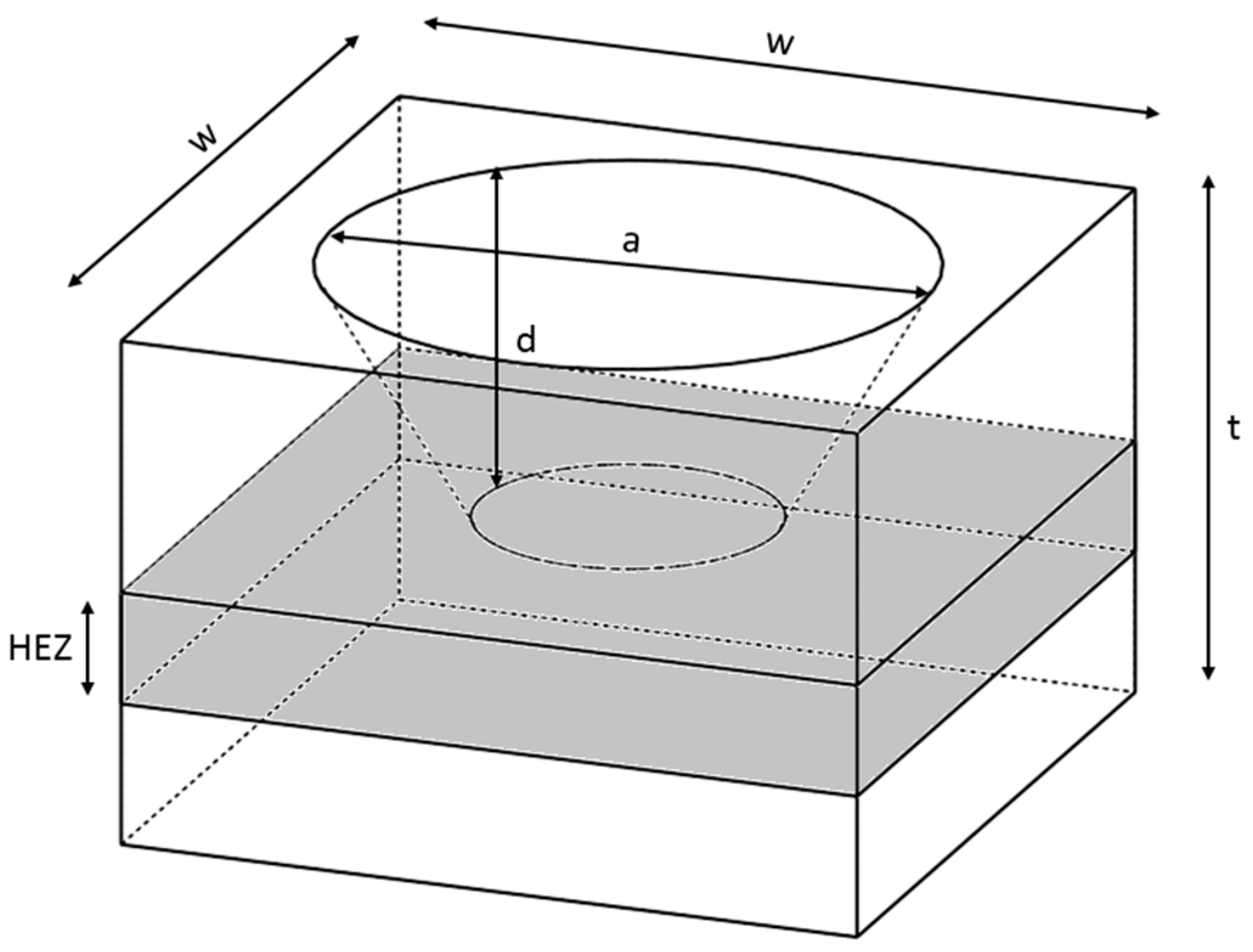
Figure 6.
Materials employed in the definition of the HEZ.
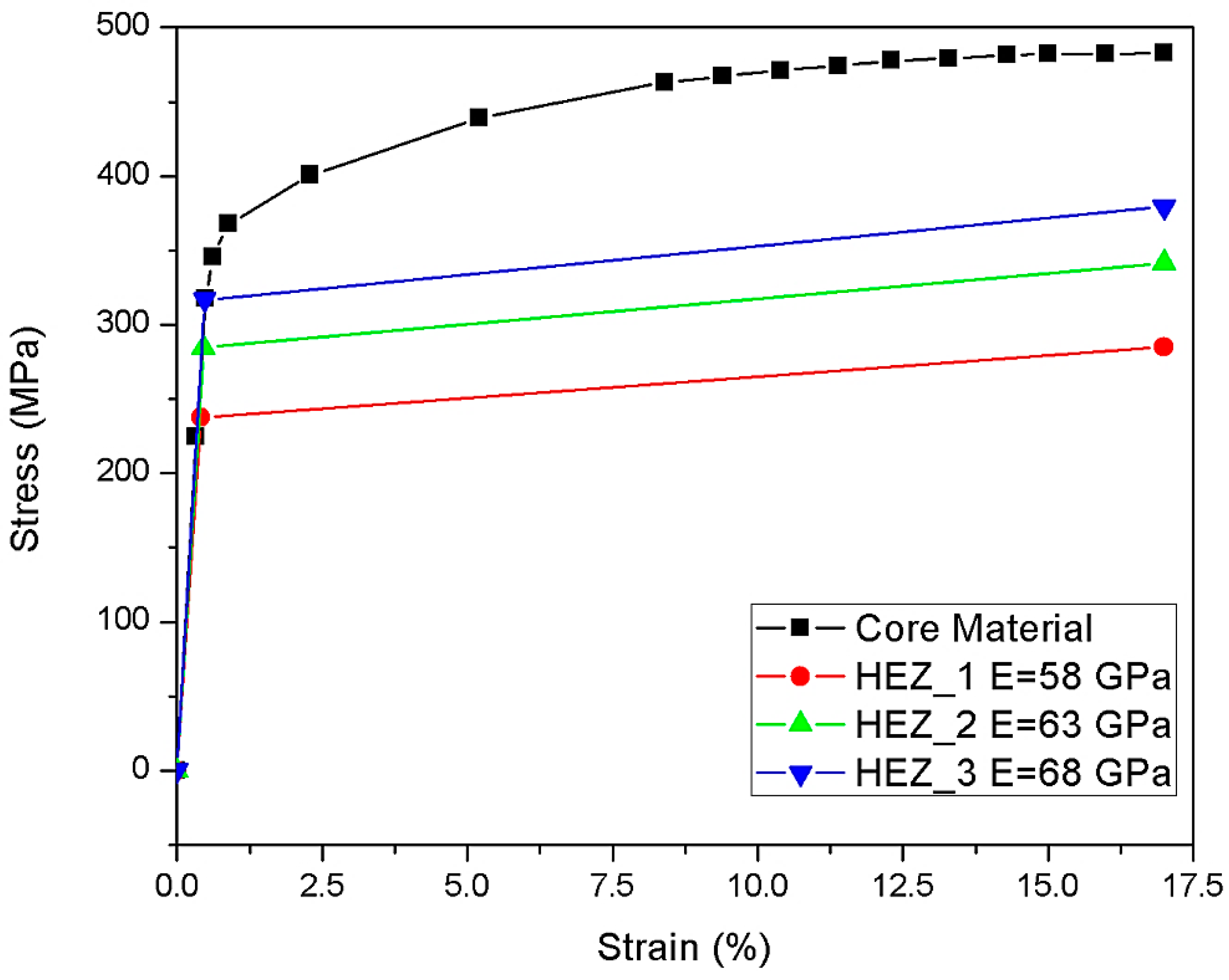
Figure 7.
Typical FE mesh and materials employed in the definition of the RUC.
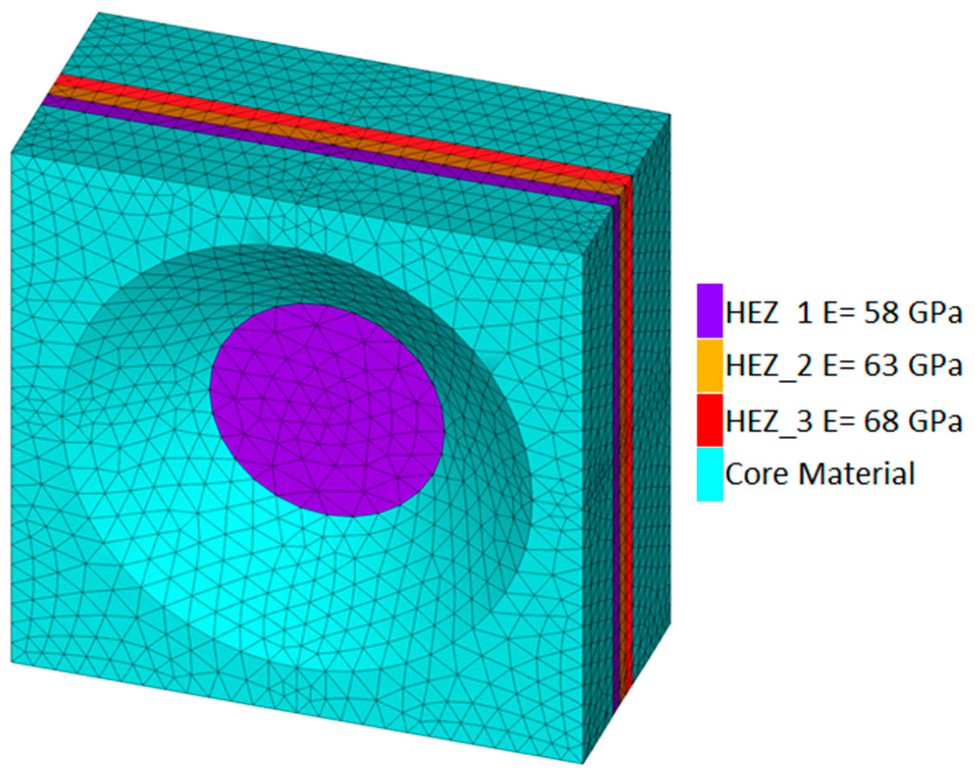
Figure 8.
RUC analyses’ results for the exfoliated areas of the top and side surfaces after 24 h of exposure (a) accounting for geometrical features of corrosion and the HEZ and (b) accounting only for geometrical features of corrosion.
Figure 8.
RUC analyses’ results for the exfoliated areas of the top and side surfaces after 24 h of exposure (a) accounting for geometrical features of corrosion and the HEZ and (b) accounting only for geometrical features of corrosion.

Figure 9.
Sequence of introduction of corrosion damage into the specimens’ FE models.
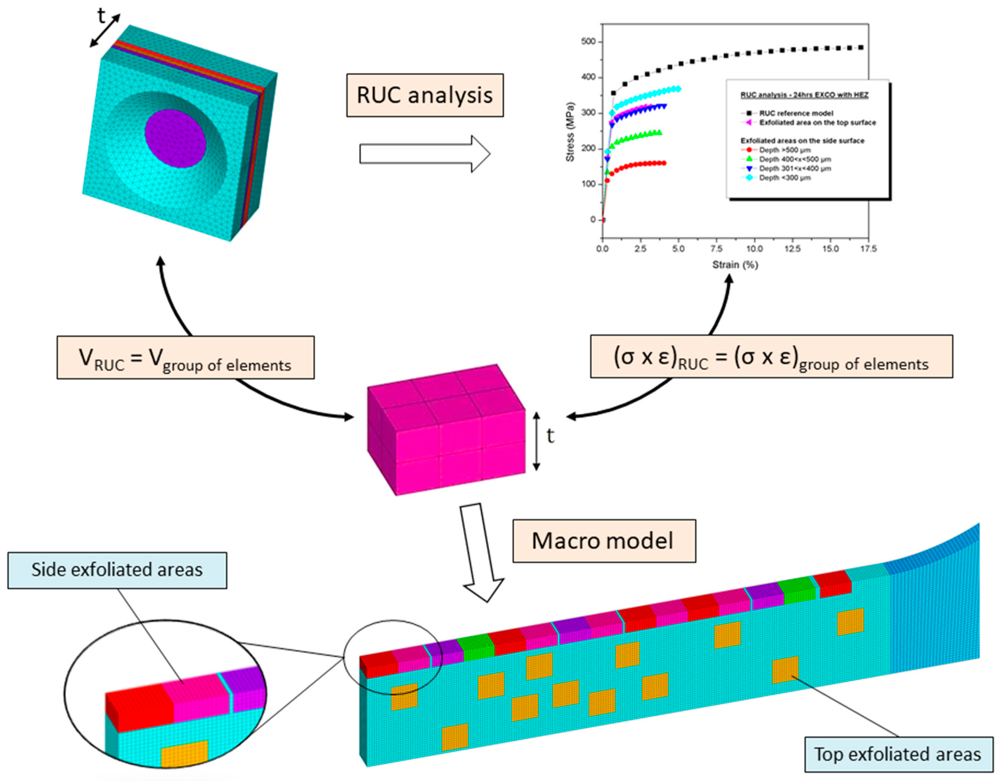
Figure 10.
Results of the convergence study performed on the effect of incremental axial displacement reduction.
Figure 10.
Results of the convergence study performed on the effect of incremental axial displacement reduction.

Figure 11.
Stress-strain curves of the corroded material, comprising the experimental results and numerical simulations, accounting for purely geometrical features of corrosion damage and the insertion of the HEZs after (a) 8 h, (b) 16 h and (c) 24 h of exposure.
Figure 11.
Stress-strain curves of the corroded material, comprising the experimental results and numerical simulations, accounting for purely geometrical features of corrosion damage and the insertion of the HEZs after (a) 8 h, (b) 16 h and (c) 24 h of exposure.

Figure 12.
Experimental and numerical reductions in elongation to fracture with corrosion exposure time.
Figure 12.
Experimental and numerical reductions in elongation to fracture with corrosion exposure time.


Table 1.
Nanoindentation hardness values (HM) and local elastic modulus (GPa) at the bottom of the pits (0 μm).
Table 1.
Nanoindentation hardness values (HM) and local elastic modulus (GPa) at the bottom of the pits (0 μm).
| EXCO Time (h) | Nanoindentation Hardness (HM) | Local Elastic Modulus (GPa) |
|---|---|---|
| 8 | 1906.8 | 35.5 |
| 16 | 2093.6 | 39.7 |
Table 2.
Input data for the estimations of the exponential evolution of HEZ’s local elastic modulus after 8 and 16 h in EXCO solution.
Table 2.
Input data for the estimations of the exponential evolution of HEZ’s local elastic modulus after 8 and 16 h in EXCO solution.
| EXCO Time (h) | Depth (μm) | Local Elastic Modulus (GPa) | ||
|---|---|---|---|---|
| x0 | x1 | y0 | y1 | |
| 8 | 0 | 100 | 35.5 | 71 |
| 16 | 0 | 150 | 39.7 | 71 |
| a = 39.96, b = 0.42, k = −0.01. | ||||
Table 3.
Representative Unit Cell (RUC) dimensions (Top surface).
| EXCO (h) | Cubic Part | Depth Range (μm) [2] | Embedded Pit | ||
|---|---|---|---|---|---|
| w (μm) | t (μm) | d (μm) | a (μm) | ||
| 8 | 790 | 480 | >100 | 165 | 177 |
| 91 ≤ d ≤ 100 | 94 | 240 | |||
| 81 ≤ d ≤ 90 | 84 | 194 | |||
| 71 ≤ d ≤ 80 | 76 | 174 | |||
| 61 ≤ d ≤ 70 | 65 | 133 | |||
| 16 | 1300 | 580 | Mean values | 203 | 921 |
| 24 | 1480 | 680 | Mean values | 233 | 1217 |
Table 4.
RUC dimensions (Side surface).
| EXCO (h) | Cubic Part | Depth Range (μm) [2] | Embedded Pit | ||
|---|---|---|---|---|---|
| w (μm) | t (μm) | d (μm) | a (μm) | ||
| 8 | 790 | 480 | >400 | 463 | 762 |
| 351 ≤ d ≤ 400 | 377 | 668 | |||
| 301 ≤ d ≤ 350 | 325 | 754 | |||
| 251 ≤ d ≤ 300 | 276 | 561 | |||
| 201 ≤ d ≤ 250 | 224 | 469 | |||
| 151 ≤ d ≤ 200 | 175 | 336 | |||
| 101 ≤ d ≤ 150 | 127 | 247 | |||
| ≤ 100 | 80 | 209 | |||
| 16 | 1300 | 580 | >500 | 564 | 1286 |
| 401 ≤ d ≤ 500 | 443 | 1056 | |||
| 301 ≤ d ≤ 400 | 345 | 1044 | |||
| ≤300 | 243 | 850 | |||
| 24 | 1480 | 680 | >500 | 660 | 1450 |
| 401≤ d ≤500 | 452 | 1340 | |||
| 301≤ d ≤400 | 357 | 960 | |||
| ≤300 | 245 | 731 | |||
© 2018 by the authors. Licensee MDPI, Basel, Switzerland. This article is an open access article distributed under the terms and conditions of the Creative Commons Attribution (CC BY) license (http://creativecommons.org/licenses/by/4.0/).
Share and Cite
MDPI and ACS Style
Vasco, M.C.; Tserpes, K.; Pantelakis, S.G. Numerical Simulation of Tensile Behavior of Corroded Aluminum Alloy 2024 T3 Considering the Hydrogen Embrittlement. Metals 2018, 8, 56. https://doi.org/10.3390/met8010056
AMA Style
Vasco MC, Tserpes K, Pantelakis SG. Numerical Simulation of Tensile Behavior of Corroded Aluminum Alloy 2024 T3 Considering the Hydrogen Embrittlement. Metals. 2018; 8(1):56. https://doi.org/10.3390/met8010056
Chicago/Turabian StyleVasco, Marina C., Konstantinos Tserpes, and Spiros G. Pantelakis. 2018. "Numerical Simulation of Tensile Behavior of Corroded Aluminum Alloy 2024 T3 Considering the Hydrogen Embrittlement" Metals 8, no. 1: 56. https://doi.org/10.3390/met8010056
Note that from the first issue of 2016, this journal uses article numbers instead of page numbers. See further details here.