Article

Investigation on the Effect of Tool Pin Profiles on Mechanical and Microstructural Properties of Friction Stir Butt and Scarf Welded Aluminium Alloy 6063

by
Pankul Goel
1,
Arshad Noor Siddiquee
2,
Noor Zaman Khan
2,*,
Mohd Azmal Hussain
3,
Zahid A. Khan
2,
Mustufa Haider Abidi
4,* and
Abdulrahman Al-Ahmari
4
1
Department of Mechanical Engineering, IMS Engineering College, National Highway 24, Ghaziabad 201009, India
2
Department of Mechanical Engineering, Jamia Millia Islamia, New Delhi 110025, India
3
Department of Mechanical Engineering, Noida Institute of Engineering and Technology, Greater Noida, Uttar Pradesh 201306, India
4
Princess Fatima Alnijris’s Research Chair for Advanced Manufacturing Technology, Advanced Manufacturing Institute, King Saud University, Riyadh-11421, Saudi Arabia
*
Authors to whom correspondence should be addressed.
Metals 2018, 8(1), 74; https://doi.org/10.3390/met8010074
Submission received: 14 December 2017 / Revised: 16 January 2018 / Accepted: 17 January 2018 / Published: 19 January 2018
(This article belongs to the Special Issue Science, Characterization and Technology of Joining and Welding)

Abstract

:
In the present study, friction stir welding (FSW) of butt and scarf joints of Al 6063-T6 were investigated. Five different tool pin profiles (cylindrical, tapered cylindrical, square, triangular, and hexagonal) were applied for performing welding. Scarf joint, being a new joint configuration, was used and effect of pin profiles was investigated on this type of joint configuration. The effect of pin profiles on microstructure, micro-hardness, impact and tensile properties of friction stir welded Al 6063-T6 was investigated. Scanning electron and optical microscopy were employed to characterize the different zones of welded joints. A thorough discussion on correlation between mechanical properties and microstructure has been made. In addition, the formation of various defects during the FSW was discussed with the help of fractography of the fractured surfaces.

1. Introduction

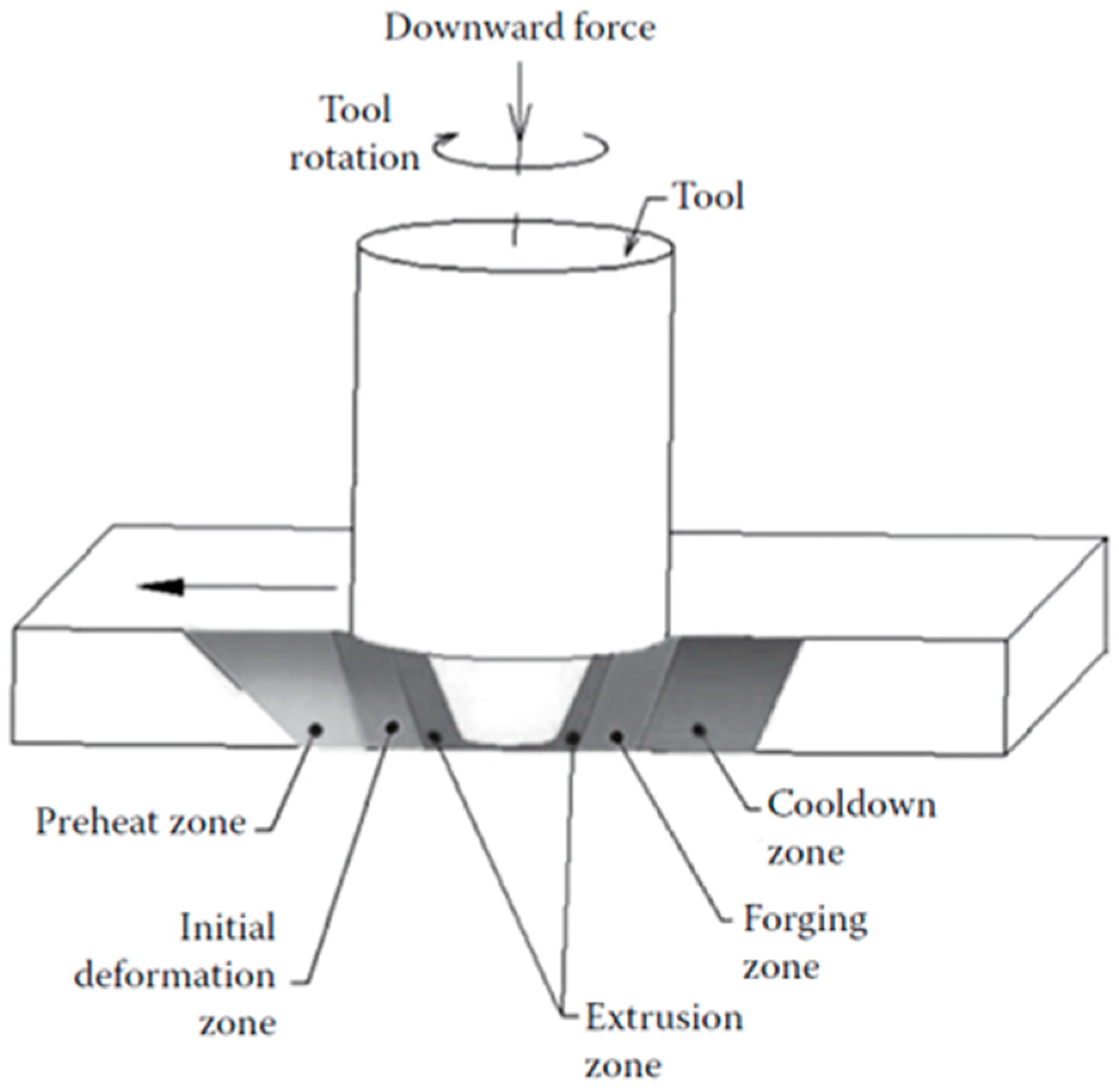
Aluminum alloy has been widely acknowledged in fabrication of lightweight structures especially for aviation, automobile and the entire transportation sector as it has high strength to weight ratio, corrosion resistance and good formability. Conventionally, for joining certain classes of aluminum alloys (e.g., age hardenable alloys), a new hot shear welding technique known as Friction Stir Welding (FSW), proved a great success [1,2,3]. It is evident from the research available that flaws like porosity and hot cracking are not found in FSW [4]. Moreover, the dendritic structure that is a characteristic feature of the fusion weld microstructure is not present in the FSW, thus any harm to the mechanical properties due its presence is just not possible [5]. There are a number of stages involved in the sequential progress of FSW process that is the pre-heating, initial deformation, extrusion, forging and metallurgical phases during heat rejection as shown in Figure 1. This process is energy efficient and environmentally friendly too [
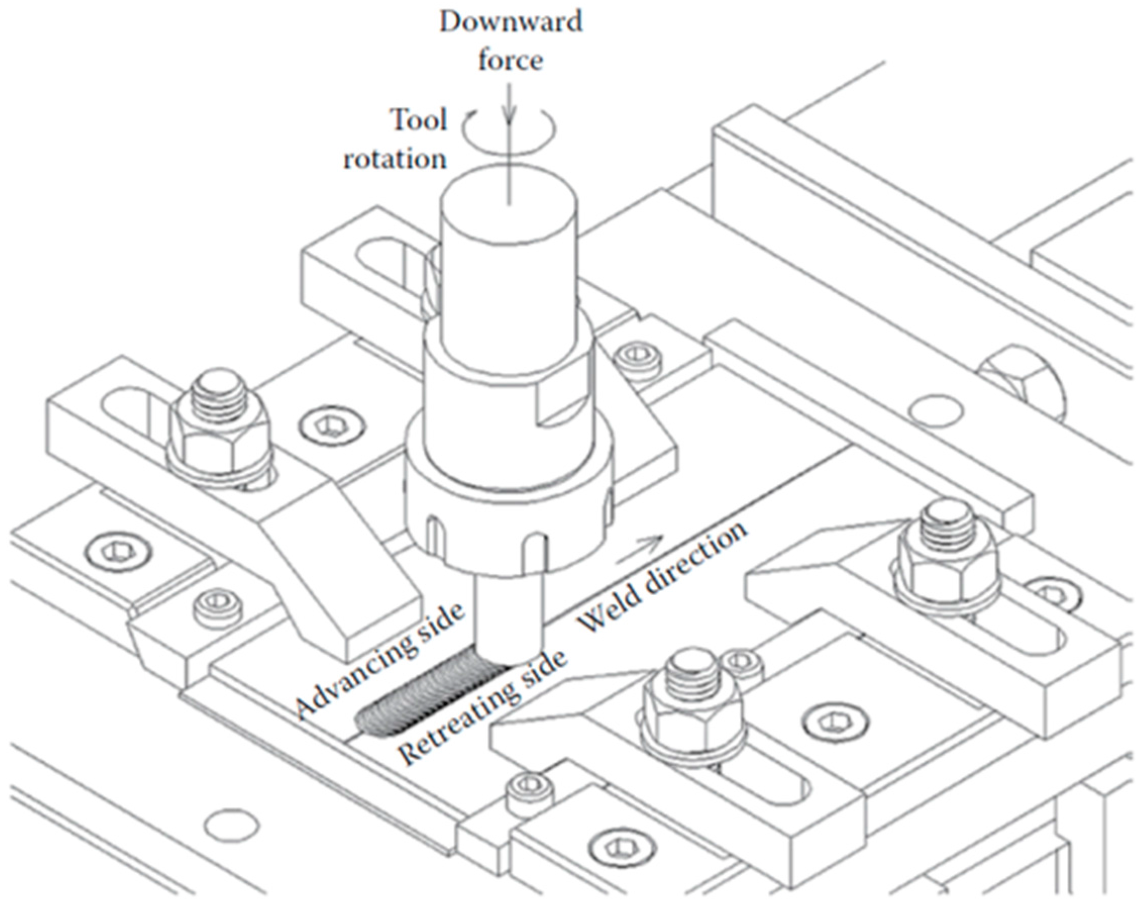
6]. Basically, the welding process operates by governing the amount of frictional heat generated between the rotating tool and the workpiece being welded, through a set of process parameters like tool rotation speed, plunge depth, welding speed, etc., in such a way so as to thermally condition the abutting joint surfaces in the severe plastically deformed region. Schematic of FSW process is presented in Figure 2.
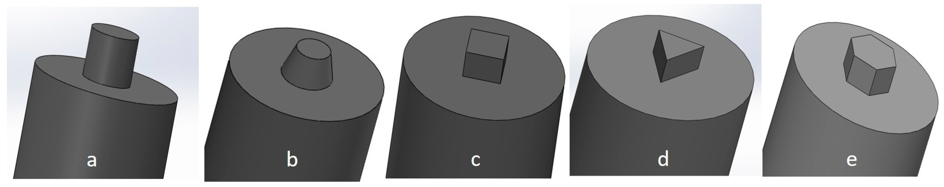
The rotating cylindrical tool used to perform FSW is comprised of a shoulder (with a specified diameter ‘D’) and a small pin or probe (of a predefined diameter ‘d’ and length ‘l’) attached to the shoulder. The pin or probe can have various geometries, and it is plunged into the faying surface of the materials being welded. The size and designs of shoulder and pin (commonly referred to as tool design) have a significant effect on heat input and material movement. The study conducted by Vijayavel et al. [8] revealed the fluctuations in the tensile strength and hardness of the friction stir processed material because of the variation in the shoulder diameters to pin diameter (D/d) ratio, and this was further linked with associated microstructural changes. Similarly, the research conducted by Khan et al. [9] stated that a D/d ratio of 2.6 gives the maximum tensile strength, whereas a D/d ratio of 2.8 results in the minimum tensile strength and microstructures showed grain refinement in the zone where the material is mixed through stirring action (known as stir zone) due to dynamic recrystallization during FSW. Therefore, the present study used the optimized D/d of 2.6 for all the experiments. Another pin/probe dimension i.e., ‘pin length’ controls the depth of penetration. The design of the probe is such that its length is less than the thickness of the plate and its diameter is typically a little larger than the thickness of the plate [10]. An adequately chosen shoulder diameter provides two important functions: (a) prevents plasticized material, being stirred, from the out of the stir zone in the form of flash and (b) sufficient amount of frictional heat input that is necessary for the softening of material. Apparently, a truncated cone shaped pin akin to shape of flow vortex of the softened material is commonly used. Both the probe and shoulder generate a fair amount of frictional heat and heat of deformation that creates almost hydrostatic condition around the surface in contact with the probe and shoulder. Thus, under the correct conditions of heat and flow material in the front moves from the advancing side (AS) to the retreating side (RS) and consolidates at the back to form a sound joint. The material from the leading edge is exported towards the trailing edge where it is forged into a joint [11]. Roughly, with every complete rotation of the tool, a sufficient amount of energy builds up to squeeze out semi-circular shells from the base material. This is exactly how the weld zone develops or it can be understood as an integrated effect of small extrusions [12]. Moreover, the investigation done by Elangovan et al. [13] shows that the shell extrusion process is responsible for grain refinement and enhancement of material properties. The enhancement of mechanical properties is mainly affected by the changes in the microstructure of the weld region resulting from dynamic recovery [14].
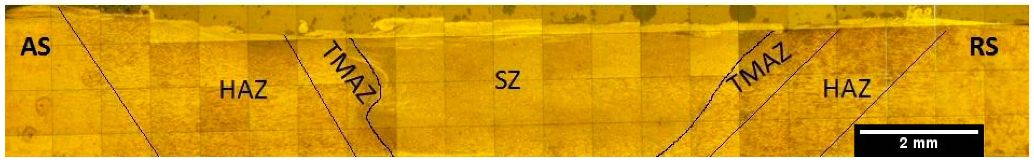
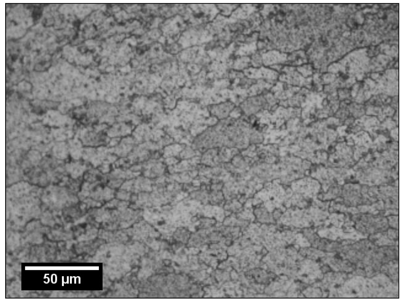
Parameters like tool geometry and joint configuration have a considerable effect on the material flow and temperature evolution, and the same is reflected in the microstructure of joints. Furthermore, as a result of this combination of frictional heat and mechanical intermixing of materials, typical micro-structural zones are evolved after FSW such as (a) the stir zone (SZ), consist of fine and re-crystallized grains, (b) the thermo mechanically affected zone (TMAZ), comprising of plastically deformed grains, and (c) the heat affected zone (HAZ) containing grains similar to base material. The fine grains structure of SZ was a result of severe plastic deformation caused by stirring action of the tool. The region next to SZ is less plastically deformed and is subjected to partial dynamical re-crystallization, and it is named TMAZ. However, no plastic deformation is seen in the HAZ region, and it only experiences a thermal effect [9]. Figure 3 shows the friction-stir welding micro-structural zones.
In case of age-hardenable alloys, the softening temperature is so high that it may lead to coarsening or dissolution of the strengthening precipitate and consequently may adversely affect the joint properties. Available literature reveals that the density, size, and distribution of the strengthening precipitates strongly affect the mechanical properties of the friction-stir welded precipitation-hardenable Al alloys [15,16,17,18,19]. Usually, during the welding thermal cycle [17,19], the strengthening precipitates are dissolved due to the heat generation and thus mechanical properties in the region around the weld may decrease.
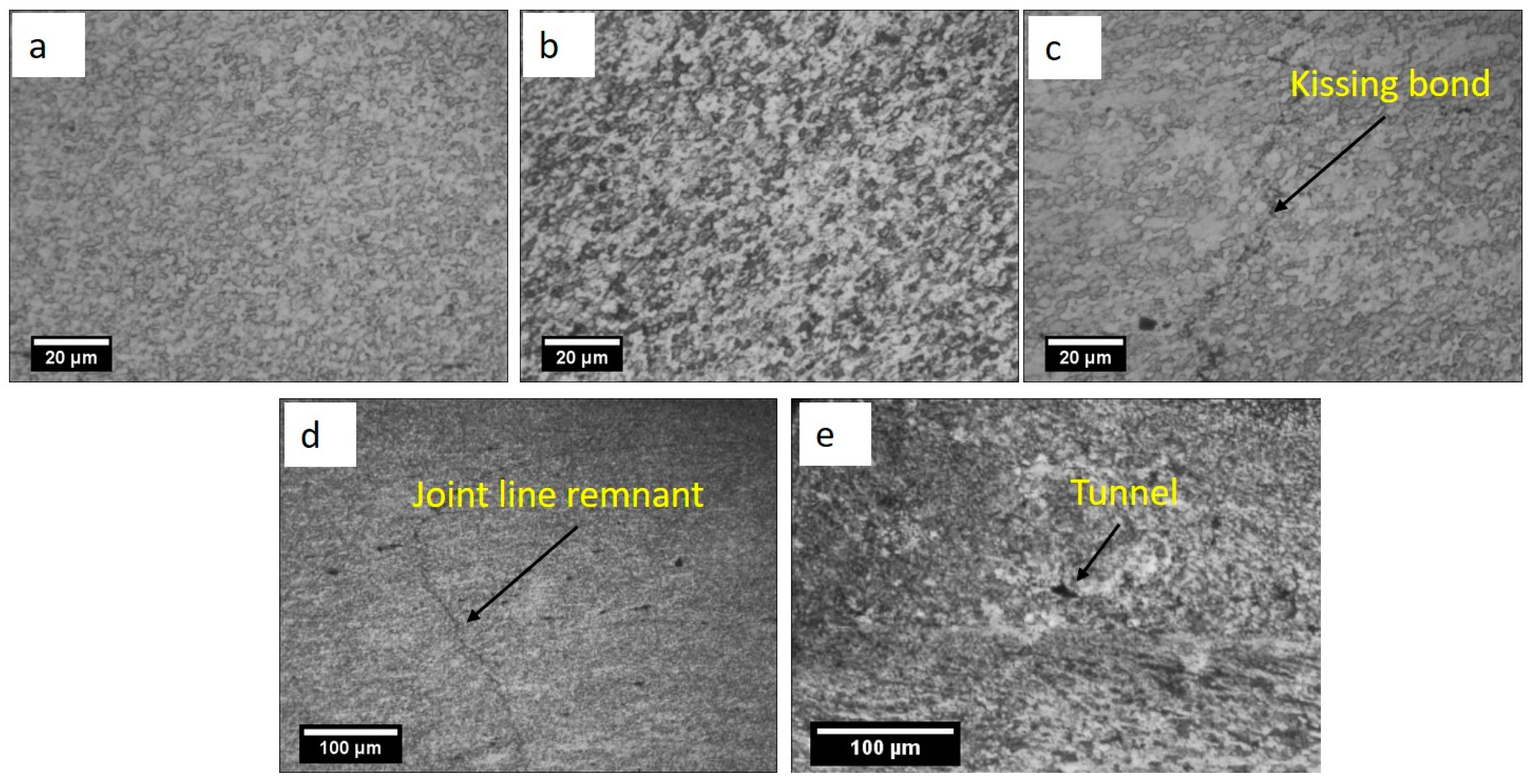
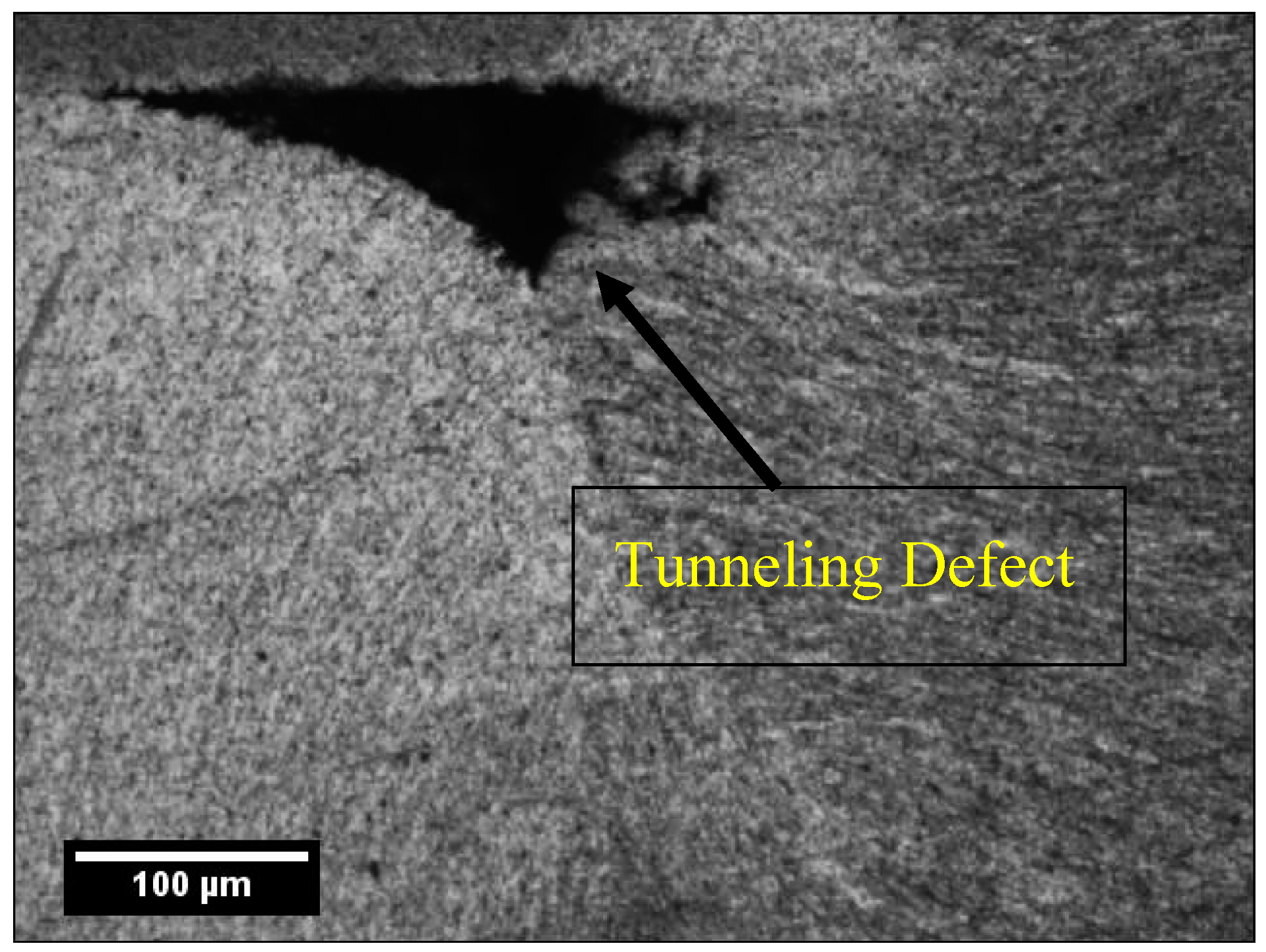
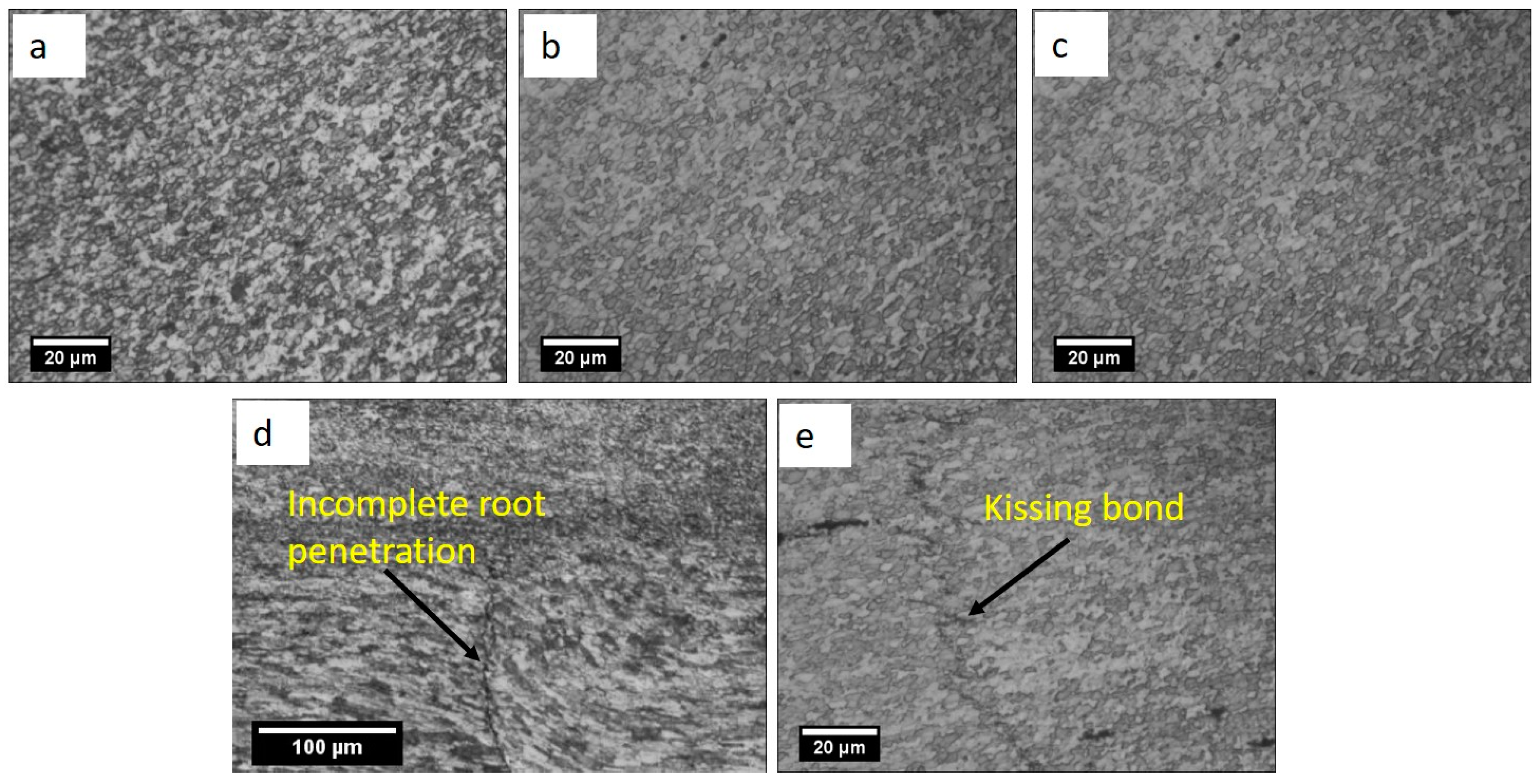
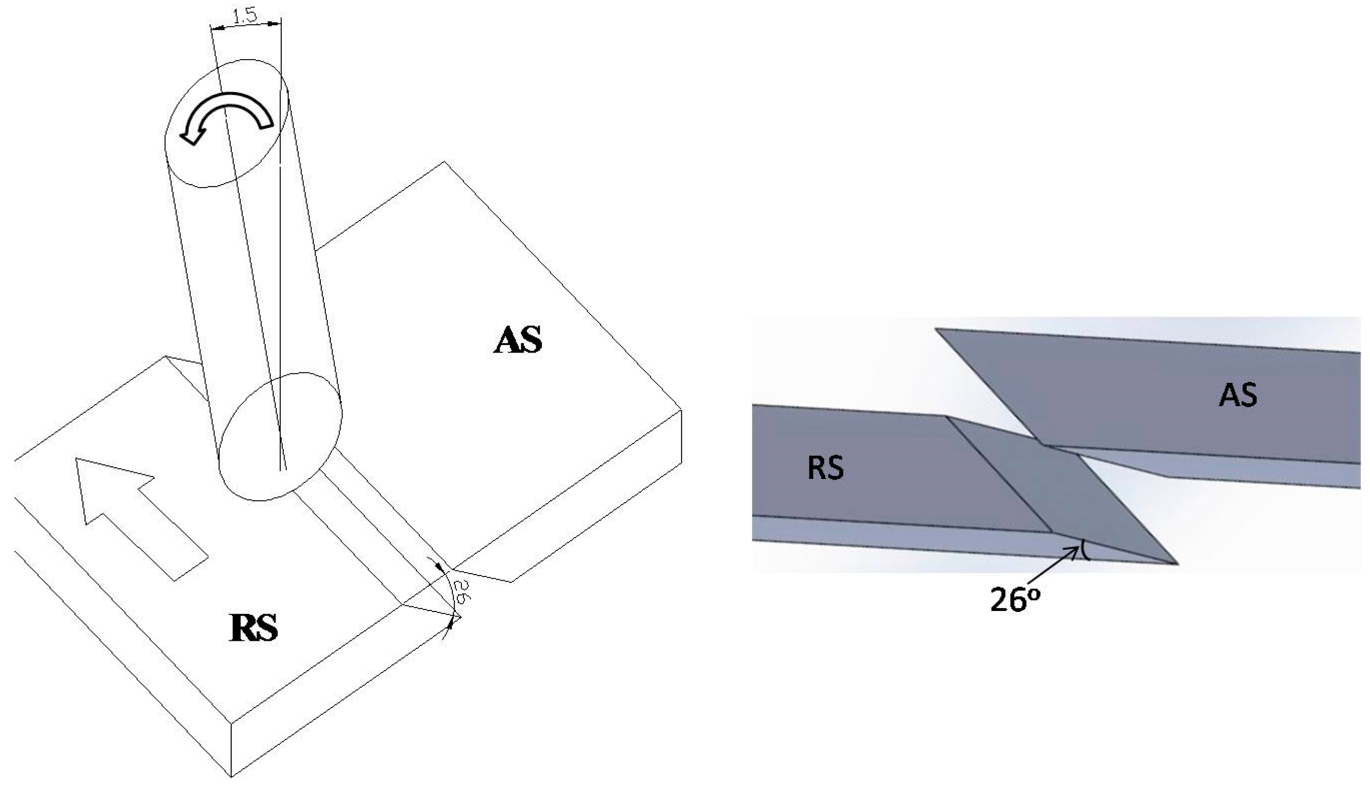
Owing to various advantages over fusion welding processes, the FSW process has its own defect such as tunneling defect, kissing bond (KB), joint line remnant, hooking defect, voids, and incomplete root penetration. These defects form due to improper material movement and inadequate heat generation caused by improper selection of process parameters, tool geometry and joint configuration. Material movement depends on several parameters including tool pin profile. These defects, if not minimized or eliminated, may lead to the degradation of mechanical properties of the joints. Defect formation in butt and lap joint configuration were investigated by many researchers [20,21,22,23,24]. Moreover, some defects such as kissing bond and joint line remnants, are typical to FSW. The main reason for these joints lies in the fact that, in the case of butt joint, the faying surface and the tool axis coincide. The velocities and flow of material at and near the tool axis are negligible and contributes to these defects. To overcome these defects, higher rpm and/or slower traverse speed are suggested. However, these conditions also add more heat, which is detrimental to age-hardenable alloys. Thus, alternate ways such as a change in joint configuration need to be explored so that they produce stronger joints of age-hardenable materials can be better understood. Incidentally, most butt welds by FSW are made in square joint configuration, which makes faying line coincidental to the tool axis. It is worthwhile to mention that shear movement is maximum at the tool periphery and ideally zero at the tool axis. In the case of a regular butt joint, the faying surface and the tool axis coincide and, because of deficient shear and flow, the chances of defect such as joint line remnant and kissing bond are high. The scarf joint has an advantage in which the abutting surface is inclined to the tool axis and can thus assist in alleviating issues that lead to some FSW defects. To the knowledge of the authors, no literature is available for the FSW with scarf joints. This paper has made an attempt to be the torch bearer in investigating the effect of scarf joints. Any further attempt to separately optimize the parameters for scarf configuration may uncover the complete potential of this type of joint. During FSW, the material undergoes extrusion at the leading edge in the AS, which churns around the edge and finally forged behind on the RS at trailing edge, thus consolidating the joint. During the course of this action, the material moves under shear through a set of stick-and-slip actions around the pin and undergoes severe plastic deformation. If the lateral surface of pins has flat faces such as in prismatic/pyramid shape, the material, which otherwise moves purely under shear, experiences support to its flow through pulsating action of the flats. Thus, the pin profile plays a significant role in material movement around the pin. While the effect of pin profiles on square butt joints has been explored by some researchers, its effect on scarf joint is not explored.

2. Experimental Method

In the present work, AA6063-T6 was applied as the base material (BM) and joined by friction stir welding in square butt and scarf joint configurations. Rectangular plates of 200 mm × 45 mm × 4.75 mm were used as welding. A 26° inverted bevel was tested to make up the scarf joint configuration. For the chosen shoulder diameter, the bevel angles were chosen based on comprehensive trail runs. For the scarf joint, the plates with inverted bevels were kept on AS as shown in Figure 4.
To investigate the effect of pin geometries, hot die steel (H13) tools with five different pin profiles such as cylindrical, tapered cylindrical, triangular, square and hexagonal (as shown in Figure 5) having 20 mm shoulder diameter, 7 mm pin diameter and 4.35 mm pin length were tested.
Chemical composition, mechanical and physical properties of Al 6063-T6 are shown in Table 1 and Table 2, respectively. Experiments were conducted on a robust vertical milling machine (Maker: Bharat Fritz Werner (BFW), Bangalore, India) adapted to perform FSW. The intimate contact between the abutting faces has a significant effect on the joint especially defect formation and thus the plates were clamped by using a robust fixture with zero root gaps and adequate lateral contact pressure. Parameters such as tool tilt angle rotational and traverse speed are key to the joint efficiency and they were carefully chosen through a rigorous experimentation. Tool tilt of 1.5° (towards the trailing side of the tool from the vertical axis of rotation), rotational speed of 900 rpm and traverse speed of 50 mm/min was used during experiments. These parameters were chosen by optimization through comprehensive trial experimentation.
The tensile and impact samples were prepared as per ASTM E-8 and ASTM E-32 specifications, respectively. A tensile test was performed on a computer interface tensometer at a cross head speed of 2 mm/min. Microstructural specimens were prepared by grinding and polishing as per standard procedure and were subsequently polished by applying 1 and 0.3 micron alumina suspension and diamond paste, respectively. The polished samples were etched with Keller’s reagent and macrographs of etched specimen are shown in Table 3. Micro-structural analysis was done on an optical microscope, whereas scanning electron microscopy (SEM, Zeiss, Jena, Germany) was applied to analyze fractured tensile samples. Micro-hardness was also traced on the transverse weld section across various weld zones. The Vickers hardness tests were conducted by means of hardness testing machine (Mitutoyo, Utsunomiya, Japan) at 2 N load and 15 s dwell time. It is worthwhile to note that the present work has been performed to investigate, demonstrate and compare the effects of pin profile on two different joint configurations. One of the joint configurations is very scantly reported in the literature; in such a situation, a microstructural analysis and its correlation to the process parameters shall be of greater importance, as it provides sound technical basis on the process mechanics. Thus, rather than a statistical analysis, discussions and analyses based on microstructure property correlation shall be more apt.
The FSW process parameters and tool geometry except tool pin profile were optimized and kept constant during the experiments and are shown in Table 4.

3. Results and Discussion

3.1. Microstructure Evolution of Butt Joint

The base material (Al 6063-T6) microstructure as given in Figure 6 shows that it consists of pancake shaped grain boundaries along with the presence of dark precipitates that are uniformly distributed.
In contrast to this, the microstructure of weld is comprised of refined grains (Figure 7 and Figure 8). Micrographs of square butt and scarf configurations are depicted in Figure 7 and Figure 8, respectively. It is evident from Figure 7 that, in square butt configuration, defects like joint line remnant, tunnel and kissing bond (zig-zag line) are produced, which is a commonly reported concern [25,26,27,28]. Moreover, such situation prevailed during several pin geometries including hexagonal, conical and triangular sections, but the size of defects is very prominent in welds made with conical pin. As shown in Figure 7e, in the case of triangular pins, the tunnels found on the AS, which indicates that the material was pulled by the leading edge of tool from AS, but the pin could not effectively stir and fill the material behind the tool, and, consequently, a void is formed.
Micrograph from the SZ of weld made with conical pin is shown in Figure 7b, which reveals that the joint possesses uniformly distributed grains along with fine particles that may be Mg2Si [29]. This contributes to enhanced joint strength and the same has been confirmed from the tensile test. The cylindrical pin profile, however, produced joint of maximum tensile strength among the other profiles used. Furthermore, zigzag lines and minute micro-cracks are also observed, which may be due to agglomerated presence of Al2O3 particles along the faying line, which could not be merged due these particles [29].
Figure 5c–e depict the micrographs of welds produced using square, hexagonal and triangular pin profiles, respectively. Defects such as kissing bond, tunnel and joint line remnant are visible in these micrographs. Furthermore, as calculated by Elangovan et al. [13], the number of pulses is equal to the product of rotation speed per second and the number of flat faces in the pin. Therefore, at a traverse speed of 50 mm/min (0.8333 mm/s) and rotation speed of 900 rpm (60 rps), the number of pulse produced per seconds were 90, 60, 45 for hexagonal, square and triangular pin profiles, respectively. Pins with flat faces like hexagonal, square and triangular produce pulsating stirring action and assist with material movement, provided the size and number of pulsations are correct. Thus, for effective pulsating action that can aid in effective stirring and homogenous redistribution of the strengthening particles, proper selection of pin-shoulder diameter is also required. However, in the present study, the employed pin-shoulder diameter shows that, in some cases, defects are present even despite pulsating action (like a tunnel defect with triangular pin profile). This may be because of the fact that the material extruded by a pulse has to be pressed by the shoulder, but, a material by a single pulsation being either too much or too less may result in defects. However, in this study, the defects that appear to occur were the results of insufficient availability of material at the site of joint due to too less material being eroded in a single pulse.
However, there is no such pulsating action in the case of cylindrical and tapered pin profiles, and so the extrusion of material by these pin profiles is in the form of continuous fine layers. Thus, the intermixing and deposition of this continuous supply of material in a limited amount are successfully accomplished by the tool shoulder (20 mm), and it is evident from the results that the strength obtained for these profiles is better than the rest of the profiles. Furthermore, study of micrographs reveals that variation in grain size and distribution of strengthening particles Mg2Si (minute black spots in the micrographs are actually Mg2Si [13]) are clearly visible.
Moreover, in the case of a triangular tool, the fall in tensile and impact strength of joints are due to the presence of the tunnel defect as seen in Figure 8. However, the appearance of the top surface of the joint may look fine, but the tunneling defect may still be present, as it exists below the surface.

3.2. Microstructure Evolution of Scarf Joint

It was quite clear from available literature that the majority of the FSW work was done over butt joint and lap joint configuration [30], whereas, in the present work, an attempt has been made to make a joint between new configurations, which was actually a combination of lap and butt joints, and it is named scarf joint configuration. From the micrograph of the SZ of scarf joints, the influence of pin profiles on the material flow and defect formation is analyzed. Moreover, the microstructure for scarf joints (Figure 9) shows that, while defects that are more serious like voids, tunnel, and cavities are either absent or significantly reduced in size. Only defects like kissing-bond, hooking (which is typically found in lap joints [31,32,33]), and zigzag lines were found in specimens of the weld produced by different pin profiles.
As shown in Figure 9a–e, in almost all the micrographs, the initial joint line of two bevel plates was clearly visible, and this was one of the reasons for the decrease in strength of the scarf joint. These surfaces, however, experienced deformations and might deviate from the original straight and flat contact interfaces. The wider kissing bond appears to be the main reason for the reduced strength; otherwise, other bulk defects such as voids, tunnels or cavities are reduced in the case of scarf joints. It is evident from Figure 9b that the SZ is comprised of elongated grains and transition from SZ to TMAZ is clearly visible. The detailed micrograph of the kissing bond flaw with a typical angled direction and a zigzag shape near its end is evident in Figure 9e.
Around the SZ and TMAZ interface, the presence of the kissing bond appears to be the extension of the hooking defect in TMAZ, although the bond width is not as wide as it is for the hooking defect as stated by Threadgill et al. [34]. Furthermore, such bonds (kissing and hooking) are imperfections due to remnant oxide films on the original workpiece surfaces, which had not broken up due to the insufficient deformation during stirring. In fact, the distribution of the oxides is strongly connected to parameters such as welding speed, and tool rotational speed brings variations in the degree of stirring produced in the material [35,36].

3.3. Mechanical Testing

The effect of different pin profiles on tensile strength is explored for butt and scarf joints of Al 6063-T6. In the case of butt joints, the tapered cylindrical pin profile showed the maximum strength (162 MPa) and toughness (26 Joule) compared to the welds made applying other pin profiles, and this may be due to grain refinement and dynamic recrystallization (DRX) in the SZ [10]. Fine grain structure increases the strength of joints because the resistance in the movement of dislocation increases, as the number of grain boundaries. Furthermore, the cylindrical pin produces joints with better tensile properties than square, triangular and hexagonal. Joints produced using hexagonal and triangular pin profiles exhibited poor tensile strength due to non-homogeneous movement of materials around the pin. FS welded butt and scarf joints fabricated with cylindrical tool exhibited the highest elongation (11.16 and 7.75 mm, respectively), whereas joints with tapered cylindrical pins showed elongation 7.95 and 7.01 mm, respectively. This difference in elongation may be attributed to coarser grains from cylindrical tool weld, which aids in stretching by allowing the grain boundaries to deform more. Scarf joints with cylindrical pins showed maximum tensile strength (137 MPa) and toughness (21 Joule) compared to joints with other pin profiles.
Furthermore, in both joint configurations, the results obtained for square, triangular and hexagonal shaped tool pin profiles are found to be weak in strength. As pulsating action produced by pins with flat faces not only on depends on the number of flat faces in the pin but also on other parameters too. Thus, the FSW process parameter combinations appear to be unable to generate sufficient temperature and the rate of stirring in which the pulsating action could be effectively engaged.
It is reported that, due to inappropriate movement and insufficient plasticization of material during FS welding, the joints are prone to defects like kissing bonds, voids, tunnel defects, etc. [37,38]. It was observed that the FS Welded joints obtained by applying triangular and hexagonal pin profiles possessed tunneling defects, which resulted in the degradation of the tensile strength as shown in Table 5 and Table 6. Similar results are also reported in literature [39].

3.4. Fractography

To reveal how the fracture occurred during tensile testing, SEM observations of the fractured section were carried out. The fracture mechanism of the joints produced by testing different tool pin profiles and over two different joint configurations are described by the typical fractographs at the mid-section of the fractured tensile specimens in Figure 10.
The SEM fractographs reveal that a combination of deep and shallow micro-voids (less in number in case of butt joints) were present (Figure 10a), whereas micro voids in the case of scarf joint configurations were seen in large numbers that are relatively big in size compared to butt joints (Figure 10b). Furthermore, ductile striations spread over a large part are also visible. Furthermore, energy dissipation in plastic strains is evident from the deep dimples at certain places in the micrograph. Finely populated deep dimples are observed in butt joints (Figure 10a), which implies typical ductile mode of fractures observed in many aluminium alloys. The scarf joint shows shear type fracture with less number of deep dimples near the SZ (Figure 10b). The ductile fracture with void nucleation and coalescence is distinct in this micrograph.

3.5. Micro-Hardness Distribution

Micro-hardness distribution in the welded joints is performed to plot the topography of hardness variations across various regions of the welds. The micro-hardness distribution across the welded samples (transverse section) of the butt and scarf joints produced by different pin profiles are given in Figure 11a,b.
It is quite evident from Figure 11a that the micro-hardness profile is “W” shaped for all butt joint samples obtained by applying different pin profiles except for the square pin profile. The available literature supports the formation of “W” shaped profile for precipitation strengthened materials. In the stir zone, the average micro-hardness is 70 HV for all the samples except square pin profiles, and it is about 85 HV for square pin profile welded samples. Square pin profiles create a maximum pulsating action and provides a higher volumetric area (swept/static volume ratio is higher) for material mixing thus results in good material mixing and higher micro-hardness. The micro-hardness further increases at the TMAZ and suddenly drops at the HAZ of the retreating side of the joint obtained using a square pin profile. The sudden increment at the TMAZ may be attributed to the intermetallic compound (IMC) formation, and its decrement in HAZ is due to the grain coarsening and dissolution of the strengthening precipitates [40,41,42,43].
The micro-hardness profile at the stir zone for butt joining is stable (see Figure 11a); however, for all the scarf joints, there is a sudden drop in micro-hardness near the centerline as shown in Figure 11b. The basic material movement in FSW is advancing to the retreating side, but the complex nature of the scarf joint requires an effective vertical material movement, which is not fulfilled completely during FSW. Thus, the formation of heterogeneous mixture at the stir zone is the possible reason for the decrement of micro-hardness in the scarf joint for different pin profiles. However, the square joint creates the maximum micro-hardness among all the joints due to the effective pulsation, which can create better material stirring and mixing.

4. Conclusions

FSW of Al 6063-T6in butt and scarf joint configuration using five different tool pin profiles (straight cylindrical, tapered cylindrical, threaded cylindrical, triangular, and square) has been successfully performed. Along with butt joint configuration, a completely new joint configuration i.e., scarf joint (lap-butt), is tried for FSW. Defects that form during the course of action were also reported and discussed, and feasible recommendations have been made to prevent their formation. Based on the results obtained, various conclusions are drawn below:
  • FS welded butt joints fabricated with Tapered Cylindrical tools exhibited the highest tensile strength (162 MPa), whereas triangular tools showed the lowest tensile strength (115.6 MPa).
  • Maximum impact strength of the FS welded butt joint is found to be 26 joules for Tapered Cylindrical tools.
  • The low strength obtained in the case of scarf joints is due to relatively new joint configuration and improper features of the joints such as inclination angle, plate positioning and improper plunge.
  • Tunnel defects are found on the advancing side of the butt joint fabricated using triangular pin profiles due to the improper flow of material and inadequate consolidation.
  • Hooking, kissing and zigzag line defects were observed in the weld zone of scarf joint configurations due to improper combination of process parameters employed for welding.
  • FSW on scarf joints has been performed on the parameter combinations, which were optimized for butt joints.

Acknowledgments

The authors are grateful to the Deanship of Scientific Research, King Saud University for funding through the Vice Deanship of Scientific Research Chairs.

Author Contributions

Arshad Noor Siddiquee and Mohd Azmal Hussain wrote the paper, Arshad Noor Siddiquee and Zahid A. Khan designed the experiment, Pankul Goel and Noor Zaman Khan performed the experiments, and Mustufa Haider Abidi and Abdulrahman Al-Ahmari analyzed the data.

Conflicts of Interest

The authors declare no conflict of interest

References

  1. Arbegast, W.J. A flow-partitioned deformation zone model for defect formation during friction stir welding. Scr. Mater. 2008, 58, 372–376. [Google Scholar] [CrossRef]
  2. Packer, S.M.; Matsunaga, M. Friction stir welding equipment and method for joining X65 pipe. In Proceedings of the Fourteenth International Offshore and Polar Engineering Conference, Toulon, France, 23–28 May 2004; International Society of Offshore and Polar Engineers: Mountain View, CA, USA, 2004. [Google Scholar]
  3. Dawes, C.J.; Thomas, W.M. Friction stir process welds aluminium alloys. Weld. J. 1996, 75, 41–45. [Google Scholar]
  4. Cabibbo, M.; McQueen, H.J.; Evangelista, E.; Spigarelli, S.; Di Paola, M.; Falchero, A. Microstructure and mechanical property studies of AA6056 friction stir welded plate. Mater. Sci. Eng. A 2007, 460–461, 86–94. [Google Scholar] [CrossRef]
  5. Rhodes, C.G.; Mahoney, M.W.; Bingel, W.H.; Spurling, R.A.; Bampton, C.C. Effects of friction stir welding on microstructure of 7075 aluminum. Scr. Mater. 1997, 36, 69–75. [Google Scholar] [CrossRef]
  6. Akinlabi, E.T.; Akinlabi, S.A. Friction stir welding process: A green technology. World Acad. Sci. Eng. Technol. Int. J. Mech. Mechatron. Eng. 2012, 6, 2514–2516. [Google Scholar]
  7. Khan, N.Z.; Siddiquee, A.N.; Khan, Z.A. Friction Stir Welding: Dissimilar Aluminum Alloys; CRC Press: Boca Raton, FL, USA, 2017. [Google Scholar]
  8. Vijayavel, P.; Balasubramanian, V.; Sundaram, S. Effect of shoulder diameter to pin diameter (D/d) ratio on tensile strength and ductility of friction stir processed LM25AA-5% SICp metal matrix composites. Mater. Des. 2014, 57, 1–9. [Google Scholar] [CrossRef]
  9. Khan, N.Z.; Khan, Z.A.; Siddiquee, A.N. Effect of shoulder diameter to pin diameter (D/d) ratio on tensile strength of friction stir welded 6063 aluminium alloy. Mater. Today Proc. 2015, 2, 1450–1457. [Google Scholar] [CrossRef]
  10. Ulysse, P. Three-dimensional modeling of the friction stir-welding process. Int. J. Mach. Tools Manuf. 2002, 42, 1549–1557. [Google Scholar] [CrossRef]
  11. Grujicic, M.; Arakere, G.; Yalavarthy, H.V.; He, T.; Yen, C.-F.; Cheeseman, B.A. Modeling of AA5083 material-microstructure evolution during butt friction-stir welding. J. Mater. Eng. Perform. 2010, 19, 672–684. [Google Scholar] [CrossRef]
  12. Mishra, R.S.; Ma, Z.Y. Friction stir welding and processing. Mater. Sci. Eng. R Rep. 2005, 50, 1–78. [Google Scholar] [CrossRef]
  13. Elangovan, K.; Balasubramanian, V. Influences of tool pin profile and tool shoulder diameter on the formation of friction stir processing zone in AA6061 aluminium alloy. Mater. Des. 2008, 29, 362–373. [Google Scholar] [CrossRef]
  14. Cavaliere, P.; Campanile, G.; Panella, F.; Squillace, A. Effect of welding parameters on mechanical and microstructural properties of AA6056 joints produced by friction stir welding. J. Mater. Process. Technol. 2006, 180, 263–270. [Google Scholar] [CrossRef]
  15. Liu, G.; Murr, L.E.; Niou, C.S.; McClure, J.C.; Vega, F.R. Microstructural aspects of the friction-stir welding of 6061-T6 aluminum. Scr. Mater. 1997, 37, 355–361. [Google Scholar] [CrossRef]
  16. Murr, L.E.; Liu, G.; McClure, J.C. A tem study of precipitation and related microstructures in friction-stir-welded 6061 aluminium. J. Mater. Sci. 1998, 33, 1243–1251. [Google Scholar] [CrossRef]
  17. Sato, Y.S.; Kokawa, H.; Enomoto, M.; Jogan, S. Microstructural evolution of 6063 aluminum during friction-stir welding. Metall. Mater. Trans. A 1999, 30, 2429–2437. [Google Scholar] [CrossRef]
  18. Sato, Y.S.; Urata, M.; Kokawa, H. Parameters controlling microstructure and hardness during friction-stir welding of precipitation-hardenable aluminum alloy 6063. Metall. Mater. Trans. A 2002, 33, 625–635. [Google Scholar] [CrossRef]
  19. Svensson, L.E.; Karlsson, L.; Larsson, H.; Karlsson, B.; Fazzini, M.; Karlsson, J. Microstructure and mechanical properties of friction stir welded aluminium alloys with special reference to AA 5083 and AA 6082. Sci. Technol. Weld. Join. 2000, 5, 285–296. [Google Scholar] [CrossRef]
  20. Dehghani, M.; Amadeh, A.; Akbari Mousavi, S.A.A. Investigations on the effects of friction stir welding parameters on intermetallic and defect formation in joining aluminum alloy to mild steel. Mater. Des. 2013, 49, 433–441. [Google Scholar] [CrossRef]
  21. Khodir, S.A.; Shibayanagi, T. Friction stir welding of dissimilar AA2024 and AA7075 aluminum alloys. Mater. Sci. Eng. B 2008, 148, 82–87. [Google Scholar] [CrossRef]
  22. Nakata, K.; Kim, Y.G.; Ushio, M.; Hashimoto, T.; Jyogan, S. Weldability of high strength aluminum alloys by friction stir welding. ISIJ Int. 2000, 40, S15–S19. [Google Scholar] [CrossRef]
  23. Khan, N.Z.; Khan, Z.A.; Siddiquee, A.N.; Al-Ahmari, A.M.; Abidi, M.H. Analysis of defects in clean fabrication process of friction stir welding. Trans. Nonferrous Met. Soc. China 2017, 27, 1507–1516. [Google Scholar] [CrossRef]
  24. Khan, N.Z.; Siddiquee, A.N.; Khan, Z.A.; Shihab, S.K. Investigations on tunneling and kissing bond defects in FSW joints for dissimilar aluminum alloys. J. Alloys Compd. 2015, 648, 360–367. [Google Scholar] [CrossRef]
  25. Chen, Z.W.; Pasang, T.; Qi, Y. Shear flow and formation of Nugget zone during friction stir welding of aluminium alloy 5083-O. Mater. Sci. Eng. A 2008, 474, 312–316. [Google Scholar] [CrossRef]
  26. Saeid, T.; Abdollah-Zadeh, A.; Assadi, H.; Ghaini, F.M. Effect of friction stir welding speed on the microstructure and mechanical properties of a duplex stainless steel. Mater. Sci. Eng. A 2008, 496, 262–268. [Google Scholar] [CrossRef]
  27. Kim, Y.G.; Fujii, H.; Tsumura, T.; Komazaki, T.; Nakata, K. Three defect types in friction stir welding of aluminum die casting alloy. Mater. Sci. Eng. A 2006, 415, 250–254. [Google Scholar] [CrossRef]
  28. Buffa, G.; Campanile, G.; Fratini, L.; Prisco, A. Friction stir welding of lap joints: Influence of process parameters on the metallurgical and mechanical properties. Mater. Sci. Eng. A 2009, 519, 19–26. [Google Scholar] [CrossRef]
  29. Cui, L.; Yang, X.; Zhou, G.; Xu, X.; Shen, Z. Characteristics of defects and tensile behaviors on friction stir welded AA6061-T4 T-joints. Mater. Sci. Eng. A 2012, 543, 58–68. [Google Scholar] [CrossRef]
  30. Iqbal, A.; Khan, N.Z.; Siddiquee, A.N. Friction stir welding of different joint configurations: A review. J. Mater. Sci. Mech. Eng. 2015, 2, 19–24. [Google Scholar]
  31. Shirazi, H.; Kheirandish, S.; Safarkhanian, M.A. Effect of process parameters on the macrostructure and defect formation in friction stir lap welding of AA5456 aluminum alloy. Measurement 2015, 76, 62–69. [Google Scholar] [CrossRef]
  32. Dubourg, L.; Merati, A.; Jahazi, M. Process optimisation and mechanical properties of friction stir lap welds of 7075-T6 stringers on 2024-T3 skin. Mater. Des. 2010, 31, 3324–3330. [Google Scholar] [CrossRef]
  33. Cao, X.; Jahazi, M. Effect of tool rotational speed and probe length on lap joint quality of a friction stir welded magnesium alloy. Mater. Des. 2011, 32, 1–11. [Google Scholar] [CrossRef]
  34. Threadgill, P.L.; Leonard, A.J.; Shercliff, H.R.; Withers, P.J. Friction stir welding of aluminium alloys. Int. Mater. Rev. 2009, 54, 49–93. [Google Scholar] [CrossRef]
  35. Sato, Y.S.; Park, S.H.C.; Kokawa, H. Microstructural factors governing hardness in friction-stir welds of solid-solution-hardened Al alloys. Metall. Mater. Trans. A 2001, 32, 3033–3042. [Google Scholar] [CrossRef]
  36. Field, D.P.; Nelson, T.W.; Hovanski, Y.; Jata, K.V. Heterogeneity of crystallographic texture in friction stir welds of aluminum. Metall. Mater. Trans. A 2001, 32, 2869–2877. [Google Scholar] [CrossRef]
  37. Rai, R.; De, A.; Bhadeshia, H.K.D.H.; DebRoy, T. Review: Friction stir welding tools. Sci. Technol. Weld. Join. 2011, 16, 325–342. [Google Scholar] [CrossRef]
  38. Zhang, Y.N.; Cao, X.; Larose, S.; Wanjara, P. Review of tools for friction stir welding and processing. Can. Metall. Q. 2012, 51, 250–261. [Google Scholar] [CrossRef]
  39. Bayazid, S.M.; Farhangi, H.; Ghahramani, A. Effect of pin profile on defects of Friction Stir Welded 7075 Aluminum alloy. Procedia Mater. Sci. 2015, 11, 12–16. [Google Scholar] [CrossRef]
  40. Bussu, G.; Irving, P.E. The role of residual stress and heat affected zone properties on fatigue crack propagation in friction stir welded 2024-T351 aluminium joints. Int. J. Fatigue 2003, 25, 77–88. [Google Scholar] [CrossRef]
  41. John, R.; Jata, K.V.; Sadananda, K. Residual stress effects on near-threshold fatigue crack growth in friction stir welds in aerospace alloys. Int. J. Fatigue 2003, 25, 939–948. [Google Scholar] [CrossRef]
  42. Prime, M.B.; Hill, M.R. Residual stress, stress relief, and inhomogeneity in aluminum plate. Scr. Mater. 2002, 46, 77–82. [Google Scholar] [CrossRef]
  43. Liu, H.J.; Fujii, H.; Maeda, M.; Nogi, K. Mechanical properties of friction stir welded joints of 1050–H24 aluminium alloy. Sci. Technol. Weld. Join. 2003, 8, 450–454. [Google Scholar] [CrossRef]
Figure 1. Stages in the Friction Stir Welding (FSW) process [7].
Metals 08 00074 g001
Figure 2. Schematic of FSW process [7].
Metals 08 00074 g002
Figure 3. Friction stir welding micro-structural zones.
Metals 08 00074 g003
Figure 4. Alignment of plates for scarf joint configurations.
Metals 08 00074 g004
Figure 5. FSW tools with different pin profile (a) cylindrical; (b) tapered cylindrical; (c) triangular; (d) square and (e) hexagonal.
Metals 08 00074 g005
Figure 6. Microstructure of the base material.
Metals 08 00074 g006
Figure 7. Butt joint micrographs obtained for specimen produced by using tools of (a) cylindrical pin; (b) tapered cylindrical pin; (c) square pin; (d) hexagonal pin; (e) triangular pin.
Metals 08 00074 g007
Figure 8. Tunnel defect in the welded joint.
Metals 08 00074 g008
Figure 9. Scarf joint micrographs obtained for specimen produced by using tools of (a) cylindrical pin; (b) tapered cylindrical pin; (c) square pin; (d) hexagonal pin; (e) triangular pin.
Metals 08 00074 g009
Figure 10. SEM fractography of the welded joints produced by (A) tapered cylindrical pin for buttjoint configuration and (B) cylindrical pin for scarf joint configuration.
Metals 08 00074 g010aMetals 08 00074 g010b
Figure 11. Micro hardness profiles of welded joints produced in (a) butt joint configuration and (b) scarf joint configuration.
Metals 08 00074 g011
Table 1. Chemical composition of AA6063-T6.
ElementAlCuMgMnFeSiTiCrZnNi
AA6063-T698.750.02800.4890.0310.2450.4260.0140.0060.02970.0029
Table 2. Mechanical and thermal properties of AA6063-T6.
Aluminium AlloyUltimate Tensile Strength (UTS) (MPa)Yield (MPa)Elongation (%)Thermal ConductivityMelting Point
AA6063-T622011014200 W/m·K616 °C
Table 3. Macrograph of friction stir (FS) welded butt and scarf joints showing different weld zones.
Pin ProfileButt SpecimenScarf Specimen
Metals 08 00074 i001 Metals 08 00074 i002 Metals 08 00074 i003
Metals 08 00074 i004 Metals 08 00074 i005 Metals 08 00074 i006
Metals 08 00074 i007 Metals 08 00074 i008 Metals 08 00074 i009
Metals 08 00074 i010 Metals 08 00074 i011 Metals 08 00074 i012
Metals 08 00074 i013 Metals 08 00074 i014 Metals 08 00074 i015
Table 4. Welding parameters that are constant during welding.
Process ParameterUnitValue
Tool rotational speedRpm900
Welding speedmm/min50
Tool tilt angleDegree1.5
Tool shoulder diametermm20
Tool shoulder surface-Flat
Pin diametermm7.3
Pin lengthmm4.5
Table 5. Butt joint configuration tensile and impact test results for different pin profiles.
Pin ProfilePeak Load (KN)UTS (MPa)Elongation (%)Impact Strength (Joule)
Tapered Cylindrical4.4162826
Cylindrical4.11601124
Square4.5158721
Hexagonal3.51175.322
Triangular3.41164.620
Table 6. Scarf joint configuration tensile and impact test results for different pin profiles.
Pin ProfilePeak Load (KN)UTS (MPa)Elongation (%)Impact Strength (Joule)
Tapered Cylindrical3.3129716
Cylindrical4.4137821
Square1.677509
Hexagonal4.4121811
Triangular1.763318

