A Review of the As-Built SLM Ti-6Al-4V Mechanical Properties towards Achieving Fatigue Resistant Designs


1
School of Engineering, RMIT University, Melbourne, VIC 3001, Australia
2
School of Engineering, University of Limerick, Limerick V94 T9PX, Ireland
3
Defence Science and Technology Group, Fishermans Bend, VIC 3207, Australia
*
Author to whom correspondence should be addressed.
Metals 2018, 8(1), 75; https://doi.org/10.3390/met8010075
Submission received: 27 December 2017
/
Revised: 16 January 2018
/
Accepted: 18 January 2018
/
Published: 19 January 2018
(This article belongs to the Special Issue Fatigue Damage of Additively-Manufactured Metallic Materials)
Abstract
:Ti-6Al-4V has been widely used in both the biomedical and aerospace industry, due to its high strength, corrosion resistance, high fracture toughness and light weight. Additive manufacturing (AM) is an attractive method of Ti-6Al-4V parts’ fabrication, as it provides a low waste alternative for complex geometries. With continued progress being made in SLM technology, the influence of build layers, grain boundaries and defects can be combined to improve further the design process and allow the fabrication of components with improved static and fatigue strength in critical loading directions. To initiate this possibility, the mechanical properties, including monotonic, low and high cycle fatigue and fracture mechanical behaviour, of machined as-built SLM Ti-6Al-4V, have been critically reviewed in order to inform the research community. The corresponding crystallographic phases, defects and layer orientations have been analysed to determine the influence of these features on the mechanical behaviour. This review paper intends to enhance our understanding of how these features can be manipulated and utilised to improve the fatigue resistance of components fabricated from Ti-6Al-4V using the SLM technology.
1. Introduction
Additive manufacturing (AM) is a promising new technology that can significantly alter how components for many different industries are manufactured, with the potential to drastically improve manufacturing efficiency. It also provides a means of manufacturing geometrically complex structures, which would otherwise require a considerable amount of time and money to manufacture with other methods. One of the exciting aspects of this evolving technology is its ability to manufacture material having a microstructure that is composed of a wide range of crystallographic phases, previously only possible in traditionally manufacturing methods through post thermo-mechanical processes [1]. Furthermore, taking advantage of the intrinsic heat treatment (IHT) of the AM fabrication process, which is associated with cyclic reheating of layers through continued layer deposition, there is the potential to induce precipitation growth in situ [2]. This, in turn, offers the AM technology the potential for material inclusion engineering towards enhancing the material mechanical properties. This application of the AM technology therefore stresses the need to develop processing parameters for the manufacture of material that can be used in the as-built condition.
Considerable research efforts have been undertaken on the qualification of parts manufactured using AM technologies, with a focus on laser additive manufacturing [e.g., selective laser melting (SLM)] for titanium alloy Ti-6Al-4V. An area of primary research is focused on the identification of the manufacturing aspects which influence the quality and the microstructure of the manufactured part/structure. With this ever-growing database of vital information on the contribution of these different fabrication aspects on the quality and microstructure of the fabricated material, further research is performed to extend our knowledge of the influence of the various possible crystallographic phases, residual stresses, layer orientations and defects on the mechanical properties of the material. These include monotonic properties, low and high cycle fatigue properties and fracture behaviour. This information is important to gain understanding on which microstructural characteristics are required to improve the fatigue resistance of the material, such as the combination of phases, orientation of grains and build layers, as well as the orientation and the types of defects. Moreover, this knowledge can be used to manufacture components with tailored microstructures, capable to improve the fatigue resistance in critical areas [3], by applying these properties to enhance crack nucleation time or crack retardation capabilities of the component in the most critical loading directions.
This paper reviews the various Ti-6Al-4V microstructures that have been achieved by using the SLM technology and the resulting monotonic, low and high cycle fatigue and fracture mechanical behaviour of machined as-built SLM Ti-6Al-4V. The corresponding microstructure, processing parameters, porosity level, build strategy and information of whether it was a single or multiple build, are also reported since this is important for the repeatability of the fabrication process and the consistency of mechanical properties obtained. The mechanical properties are discussed in reference to the micro-mechanism which may have contributory role, which, in turn, offers a more in-depth understanding of how the build orientation, defects and microstructure can be utilised by selecting the most appropriate crystallographic phases, layer and build orientation in the manufacture of fatigue resistant SLM Ti-6Al-4V.
2. Microstructure of Ti-6Al-4V Manufactured by Selective Laser Melting (SLM)
2.1. α Microstructure
As indicated by Vrancken et al. [4], during the SLM process, the microstructure development is dependent on the processing parameters, including the layer thickness, scan strategy, scan spacing and speed and laser power. A widely reported microstructure of SLM Ti-6Al-4V is the acicular martensite in columnar prior- grains [5,6,7,8,9]. The development of this microstructure is commonly attributed to the processing parameters during manufacture, resulting in a cooling rate greater than 410 K [10] above the martensite start temperature, which promotes martensite growth [11]. The prior grain boundaries are elongated in the build direction due to the heat conduction.
The type of martensite present can be a combination of primary martensite, secondary martensite, tertiary martensite and quartic martensite, varying in size from 1–3 m of primary martensite to less than 20 nm for quartic martensite. It was shown by [12] that the presence and amount of the differently sized martensite depends on the influence of thermal cycles caused by the reheating of deposited layers. There is also the possibility that the microstructure contains a combination of lamellar and acicular /, which was shown by Yang et al. [13] to be caused by the melt pool geometry increasing the deposited layer thermal cycles, which in effect promotes the diffusive transformation of .
2.2. (α + β) Microstructure
Improved ductility in Ti-6Al-4V, without sacrificing severely the yield strength of the material, can be achieved by obtaining a microstructure which contains lamellar (α + β) [14]. In situ transformation of the α’ martensite to lamellar (α + β) has been previously achieved by Xu et al. [15] and Xu et al. [16] by altering the focal offset distance (FOD) and the energy density (E) in a way to promote intrinsic heat treatment (IHT). Simonelli et al. [17] demonstrated the potential to achieve varying α + β microstructures by utilising the cyclic reheating associated with layer deposition, in conjunction with controlling the build platform temperature and thermal stresses. A combination of lamellar (α + β), equiaxed (α + β), bimodal lamellar (α + β) and equiaxed α was observed through the height of fabricated specimens. This recognises the varying influence that build platform temperature and thermal stresses have on the microstructure formation. This finding was further supported by the work of Ali et al. [18], in an investigation of the effects of powder bed preheating, which highlighted the significant influence of the powder bed temperature on the SLM Ti-6Al-4V microstructure formation. In particular, preheating the powder bed at different temperatures resulted in slowing the cooling rate, promoting α’ decomposition into α and growing β between α laths. Although it is possible to achieve such a microstructure from an initial α’ martensite microstructure, using post heat treatment or hot isostatic heating (HIP), as previously reported in [4,6,19,20], the advantage of in situ microstructure tailoring is important for a number of reasons (e.g., reduction of manufacturing cost and time and tailoring the microstructure to improve mechanical performance).
Further improvements efforts in the in situ transformation of α’ martensite have been achieved by Xu et al. [9] towards overcoming the difficulties associated with the FOD adjustment and the high microstructure sensitivity to FOD. In their work, transformation was achieved by employing a scanning strategy which uses the residual heating of new layers on previous layers to maintain the temperature profile in order to ensure α’ martensite transformation into α + β. This technique offered the correct environment for the formation of a different microstructure, composing of α’ + (α + β), ultrafine lamellar (α + β) and coarse lamellar (α + β). Depending on the support structure, layer thickness and part dimension, a varying α lath width can be achieved. In parallel to this work, Barriobero-Vila et al. [21] proposed a laser scanning strategy which took advantage of the benefits offered by a longer IHT exposure time, so as to ensure α’ martensite decomposition into α + β by using porosity-optimised processing parameters previously developed by Kasperovich et al. [22] and a tight hatch distance. Both studies demonstrate the evolving achievements in microstructure design control methods and the importance of localised cyclic reheating as one of the means to achieve tailored microstructure. With the continuous improvement in understanding the SLM processing features and characteristics, the capabilities of the SLM technology are becoming more apparent. Rather than attempting to manufacture Ti-6Al-4V with comparable mechanical properties to that of the wrought Ti-6Al-4V, the technology is on the cusp of being able to offer tailored microstructures providing optimised mechanical properties.
2.3. Microstructures Examined
The main Ti-6Al-4V microstructures discussed in this paper are:
- Bimodal (duplex) microstructure, composed of lamellar (α + β) colonies and interconnected equiaxed primary α.
- Lamellar (α + β) microstructure, composed of α lamellae within β grains.
- Equiaxed (globular) microstructure, consisting of equiaxed primary α with β along the grain boundaries.
- Acicular α’ martensite.
3. Build Defects and Residual Stresses
3.1. Build Defects and the Influence of Gas Flow
The emergence of various defects during AM of metals has been studied by many researchers and has recently been reviewed by Grasso and Colosimo [23]. The formation of spherical pores is a commonly occurring defect, which, as indicated by Vilaro et al. [20], is caused by the presence of gas among the powder particles dissolved in the melt pool, which remains in the material due to rapid solidification. Spherical defects’ initiation has also been shown to be driven by the processing parameters. For example, Gong et al. [24] showed that the processing parameters have a significant influence on the size and density of defects due to the differences in the melt pool characteristics. In particular, Gong et al. [24] discovered that at higher energy density, the defects obtained a spherical shape, which was attributed to mechanically scraping ejected solidified particles. Irregular shaped defects are usually the effect of lack of fusion/melting. As discussed by Vilaro et al. [20], this is caused by incorrect processing parameters, which leads to insufficient reheating of the previous layer, preventing optimal fusion between the layers. The processing parameters’ influence has also been reported by Panwisawas et al. [25], who explored the different ways that spherical pores can become elongated through increased laser scan speed. Furthermore, Gong et al. [24] showed that at low energy densities, the defects are becoming more irregularly shaped due to insufficient layer melting. The occurrence of such defects has also been confirmed by Kasperovich and Hausmann [26], who observed elongated voids perpendicular to the build direction, occurring from insufficient energy density.
The SLM manufacturing process requires an inert atmosphere achieved with a gas flowing across the build platform. The gas flow in the chamber can also have an influence on the porosity level of the manufactured components. It has previously been reported by Kong et al. [27] and Ferrar et al. [28] that the gas flow is not uniform across the build chamber, which effectively causes a build-plate location dependence. Inadequate gas flow can cause a reduction in the removal of vaporised powder (condensate) produced by the melting process. In the study of Ferrar et al. [28], it was discovered that the low gas flow regions correspond to a variation in the intensity, spot diameter and energy of the laser beam, because of the presence of the condensate. This leads to a reduction in the effectiveness of the originally defined processing parameters on successive layer melting and fusion, potentially introducing lack-of-fusion defects. In addition, the layer thickness can be affected by the inefficient removal of the by-products (condensate, ejected powder and spatter) that occur during the melting process, which increases the potential of lack of fusion defects [29]. Ladewig et al. [29] also linked areas of lack-of-fusion defects with regions where the effects of low gas flow rate induced laser beam and by-product interaction had occurred.
3.2. Residual Stresses
Residual stresses of the most significant importance are those associated with a variation across the whole part (referred as type I residual stresses), rather than those occurring at atomic level [30]. As described in the works of Mercelis and Kruth [30] and Knowles et al. [31], these residual stresses develop during the build process due to the expansion and contraction interaction between the layers. These have been measured in a number of SLM Ti-6Al-4V builds, e.g., as reported by Leuders et al. [32] and Simonelli et al. [8]. Nickel et al. [33] and Shiomi et al. [34] demonstrated that the development of residual stresses is dependent on laser scan, while Klingbeil et al. [35] showed that this may be also geometry-dependent. Furthermore, one may note that residual stresses can vary across the thickness of the built part, as measured by Casavola et al. [36]. However, it is possible to reduce the residual stresses in situ, namely during the fabrication process. For example, a residual stresses’ reduction scheme has been recently proposed by Ali et al. [18], whereby it was demonstrated that reduction can be achieved by increasing the preheat temperature of the powder bed (reducing effectively the thermal gradient). Furthermore, it was shown with heat transfer numerical simulations that employing optimised scanning strategies can reduce the build-up of residual stresses [37].
4. Influence of the Microstructure, Residual Stress and Porosity on Mechanical Properties
4.1. Laser Scanning Strategy, Build Orientation and Type Test Coupons
The laser scanning strategies used in the fabrication of SLM-produced parts and mechanical test coupons varies greatly between researcher studies. Commonly employed strategies, as reported in the literature, are illustrated schematically in Figure 1.
Moreover, the tensile and fatigue test coupons used in axial tests vary in build orientation and type (flat or cylindrical). Build orientations used in coupon fabrication, with a corresponding reference label to indicate the direction, are summarised graphically in Figure 2.
Compact-tensile (CT) test coupon build orientations are commonly used by researchers, these are summarised in Figure 3. The corresponding build direction is also indicated in the figure (corresponding to the Z axis).
4.2. Monotonic Properties
4.2.1. Behaviour under Tension
The monotonic properties of various as-built SLM Ti-6Al-4V microstructures have been extensively studied with the use of different test coupon build orientations, as reported recently by Lewandowski and Seifi [38] (2016) and Tong et al. [39].
The microstructures investigated include (summarised literature presented):
The yield stress and elongation values measured in these studies are plotted in Figure 4, offering a better visualisation of the variation of the values for different microstructures, build orientations and porosity levels (these are summarised in Table 1 for each of the test results shown in Figure 4). Moreover, the processing parameters that have been used for the fabrication of the test coupons are listed in Table 2. The improvement in elongation achieved with a lamellar (α + β) is evidenced in the results obtained by Xu et al. [9] (Xu 1) and Xu et al. [15] (Xu 2), which is presented in Figure 4. What is also observed in Figure 4 is the significant scatter in the results obtained from α’ martensite coupons, suggesting that defects have an appreciable impact on the mechanical properties.
4.2.2. Behaviour under Torsion
The monotonic torsional behaviour of vertically (Z axis) fabricated SLM Ti-6Al-4V has been recently reported in [47], where the as-built, as-built annealed and machined annealed conditions were examined. The mechanical properties of the machined coupons are listed in Table 3, with the microstructure characteristics and processing parameters summarised in Table 4 and Table 5 respectively. The SLM material results have also been compared against the wrought bimodal Ti-6Al-4V results. In [47] it was reported that the yield strength of the SLM coupons was higher than that of the wrought material, while the ductility of the SLM coupons was less, analogous to results reported for monotonic tension tests obtained from α’ martensite SLM coupons.
4.2.3. Micro-Mechanism Contribution
As discussed by Simonelli et al. [8], the higher yield stress in monotonic tensile tests for the α’ martensite microstructures and ultrafine lamellar (α + β) and the monotonic torsion tests α’ martensite microstructure, may be attributed to the smaller α colony size which slows down the onset of plastic deformation (a consequence of a greater hindrance to dislocation movement enforced by dislocation tangling at grain boundaries). Furthermore, the increase in ductility in the lamellar (α + β) can be attributed to the plasticity of the α + β phases; the effective slip length in the α’ martensite microstructure is within single grains, while the β phase present in the lamellar (α + β) allows for slip transfer between the two phases [8]. This increases the dislocation movement and, therefore, ductility.
The influence of the microstructure on mechanical properties is complicated by inclusions, which may be formed during the fabrication process. Inclusions may cause the deformation behaviour of a α’ martensite Ti-6Al-4V microstructure, developed using SLM, to be different from a similar acicular α’ martensite Ti-6Al-4V microstructure formed from classical heat treatment and rapid cooling. The inclusions are formed on the melt pool’s surface and include hard-alpha (α), amorphous CaO, and microcrystalline Al2O3 [48]. The influence of inclusions on the micro-mechanical behaviour of the material requires further investigation. Rather than being detrimental to the fabrication process, as indicated by Hennig et al. [49], the phase transformation and stability controlling potential of impurities could be harnessed to favourably modify the mechanical properties.
Build orientation is also a factor requiring closer investigation. Anisotropy in monotonic yield strength is the consequence of a number of different microstructural characteristics. The α phase present in the test coupons contributes to the yield strength anisotropy, since α titanium is plastically anisotropic [50], therefore, orientation of the grains to a preferred slip system promotes dislocation movement. This has been confirmed by the Yang et al. [51] study which discovered that vertically built coupons contain a larger number of grains in a stress state, which are easier to slip than horizontal coupons.
It is also important to note that defects may influence anisotropy, since they have an effect on the yield strength, depending on their orientation to the loading direction, which may explain the anisotropy in yield strength between orientations [42].
The presence of defects can also explain the difference in ductility between the build orientations. As suggest by Vilaro et al. [20], defects associated with lack-of-fusion are aligned with the layers; therefore, the defects will have a greater influence on the vertically built material due to the loading pulling apart the defects, as opposed to the horizontally built material where the loading is pulling it closer. Due to the variability in the number of defects in builds reported in the studies, the influence of defects on ductility may offer an explanation as to why some studies report lower ductility in vertically built coupons, such as that reported by Vilaro et al. [20], while others, such as Qiu et al. [6], report higher ductility. Moreover, the possible reason for some studies reporting similar ductility in both vertically and horizontally manufactured coupons, such as Rafi et al. [45], could be the consequence of a balance existing between the influence of slip surfaces and defects.
4.3. Monotonic Properties
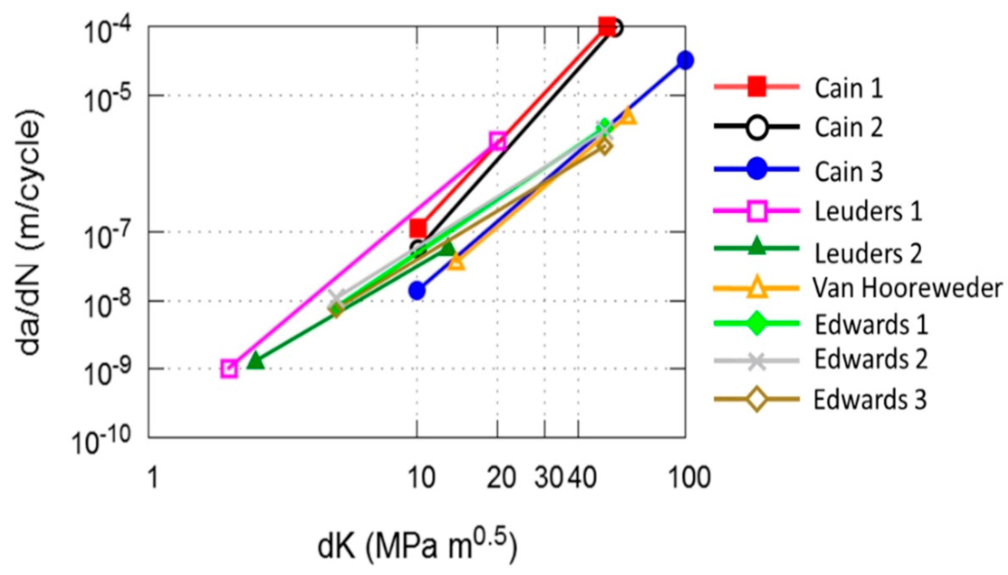
Figure 5 provides a comparison of the fatigue crack growth rate (FCGR) (da/dN, where a is the crack length and N the number of cycles) in the Paris-region between results obtained from published literature. The results were gathered using machined as-built test coupons having the microstructure characteristics presented in Table 6, fabricated with the processing parameters shown in Table 7. One may note that the XZ and ZX coupons have very similar FCGR [40]. The XZ orientation corresponds to the crack growth occurring perpendicular to the build layers but parallel to the prior columnar β grains. While, the ZX orientation corresponds to crack growth parallel to the build layers but perpendicular to the prior columnar β grains. This was contradictory to what was reported by Leuders et al. [32] who observed an increased crack growth resistance in the ZX orientation, when compared to that of XZ. The highest crack growth resistant orientation reported by both Cain et al. [40] and Van Hooreweder et al. [52] was the XY orientation, which corresponds to crack growth occurring perpendicular to both the build layers and prior columnar β grains.
Micro-Mechanism Contribution
Microstructure features, such as the grain size and morphology, can influence the crack growth of the material [54]. Increased grain boundaries due to larger grain size can create resistance to crack propagation, therefore, varying the size of the grains is likely to influence crack growth. However, crack propagation may also be dependent of the build orientation. In the recent work of Galarraga et al. [55], on Ti-6Al-4V manufactured by electron beam melting (EBM), crack propagation rate parallel to the build direction was lower than that corresponding to the perpendicular build direction. This was attributed to the prior β grain boundaries and the deflection of the crack caused by the scanning layers, which increased the tortuosity of the crack path (reducing the rate of propagation). This phenomenon is likely to explain the difference in FCGR between the Leuders 1 and Leuders 2 [32] results shown in Figure 5, where Leuders 2 [32] has a slower crack growth rate. Moreover, this may explain the low FCGR values observed in Cain 3 [40] and Van Hooreweder [52]. However, Cain 1 [40] has the same orientation to Leuders 2 [32] but the FCGR in Cain 1 is comparable to Cain 2, which has a grain and layer orientation, which according to Galarraga et al. [55] should produce higher FCGR values. This may be attributed to the influence of residual stresses. As reported by Leuders et al. [32], the two main factors influencing crack growth in SLM Ti-6Al-4V are residual stresses and microstructure. Further analysis of the results obtained by Cain et al. [40] highlighted the potential occurrence of tensile residual stress near the lateral edges of the fracture plane, which would ultimately add to the tensile loading and, therefore, increase the rate of crack propagation. However, the Edwards 1, 2, 3 results [53] in Figure 5 show very little difference in FCGR between the orientations, which was hypothesised by Edwards and Ramulu [53] to be the consequence of the influence of residual stresses. Consequently, further progress into the understanding of the influence of grain boundaries and residual stresses has to be achieved to investigate the contribution of these micro-mechanisms on crack growth.
The currently available crack growth data on AM Ti-6Al-4V has been limited to long cracks, however, fatigue cracks can exist as also physically-small cracks, and microstructurally-small cracks [56]. The difference lies on their crack length and width [57]. A long crack has a crack length and width much larger than the characteristic microstructural size scale. A physically-small crack once again has crack length and width larger than the characteristic microstructural size scale but has a crack length less than the equilibrium shield zone [region which is associated with crack closure effects [56,57]. Microstructurally-small cracks are those which have a crack length and width smaller than the shield zone and characteristic microstructural size scale. The fatigue crack growth behaviour of all these cracks can be different. This is why it is important to improve our understanding of the fatigue crack growth behaviour of all types of cracks in the material, so as to develop a broader understanding of fatigue resistance capabilities of the material [56].
Although no investigation has been undertaken into analysing the fracture behaviour of other possible as-built SLM microstructures, it would be useful to progress our understanding on the potential influence of possible phases present in a SLM Ti-6Al-4V microstructure using existing knowledge from the wrought counterpart. As suggested by Nalla et al. [57], crack propagation of microstructurally-small cracks is slower in the fine grained wrought bimodal and equiaxed (α + β) microstructures, due to higher grain boundary density. However, as reported by Tao et al. [58], acicular α’ microstructures have longer slip paths, which, in turn, promote microstructurally-small crack growth; while coarse lamellar (α + β) microstructures contain aligned α, which aids in microstructurally-small crack propagation due to long planar slip bands. Long cracks in a coarse lamellar (α + β) microstructure have slower growth rates than a bimodal microstructure [57], which is the consequence of a more torturous crack path. One may also expect that long crack growth in acicular α’ martensite microstructure will be faster than a bimodal or lamellar microstructure, since the crack path of an acicular α’ martensite microstructure is less tortuous than a bimodal microstructure [58].
4.4. High Cycle Fatigue Behaviour
4.4.1. Axial Fatigue Loading
In high cycle fatigue (HCF) assessment it is important to consider the influence of the different features of the manufactured material. In a recent critical review by Li et al. [59], the HCF performance of various SLM coupons was evaluated. Due to the varying stress ratios (R) between tests conducted by different researchers, to provide a means of comparing results, the fatigue data can be normalised using the method applied by Li et al. [59]. This method uses the effective maximum applied stress (), representing the effective maximum applied load at a stress ratio R = −1.0. is given by Equation (1), where is the actual maximum applied stress for an applied stress ratio (R). The value of the exponent is a material constant which was determined by Li et al. [59] using Ti-6Al-4V fatigue data obtained from stress ratios between −0.5, and 0.5. Using the effective maximum applied stress, the HCF performance could be compared independent of the stress ratio.
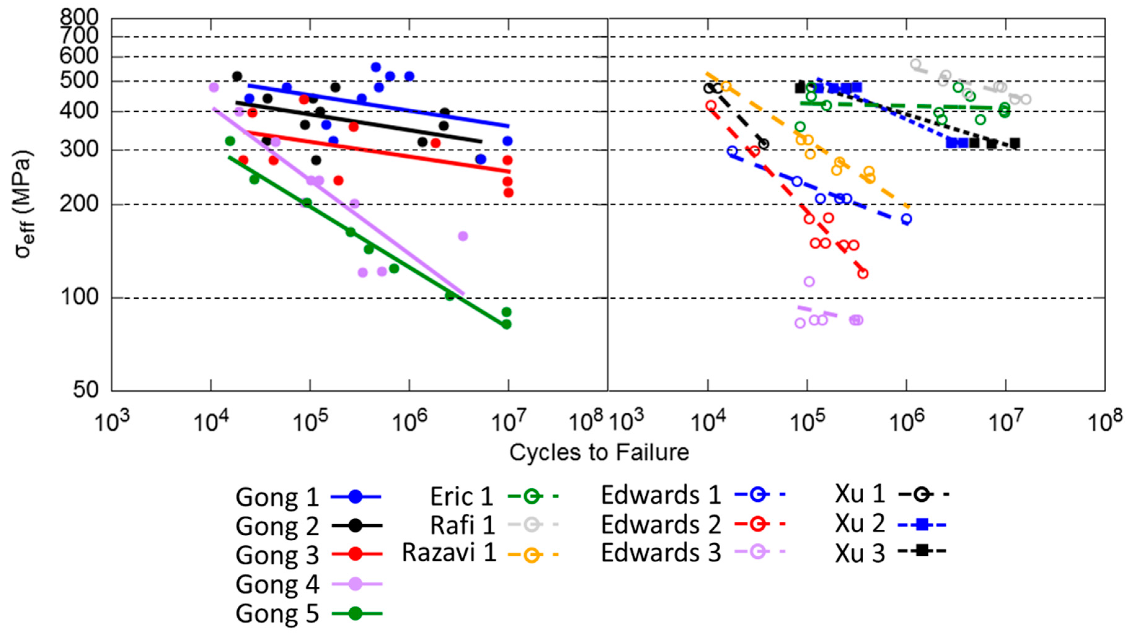
In Figure 6, various HCF test results from the literature are compared. It is noted that the comparison is limited to results obtained from machined surface coupons, to negate the influence of surface defects on the fatigue life results.
4.4.2. Torsional Fatigue Loading
Torsional HCF investigation was undertaken by Fatemi et al. [47] on annealed SLM Ti-6Al-4V, hypothesised to be composed of an α’ martensite microstructure (material features and processing parameters are provided in Table 10 and Table 11 respectively). These results were compared to bimodal Ti-6Al-4V in both shear strain and stress control, presented in Figure 7. Under both control methods, the wrought material resulted in having higher HCF resistance, as opposed to the SLM Ti-6Al-4V, as indicated by the higher cycles to failure for higher strain and stress amplitudes.
4.4.3. Micro-Mechanism Contribution
Comparing the Gong 1 and Gong 5 results [42] in Figure 6, it is noticed that the influence of porosity on HCF is profound, where the higher porosity content of the Gong 5 test coupons show significantly less cycles to failure than the denser Gong 1 coupons. This may be attributed to the pores, affecting the rate at which the crack initiation stage activates, with the definition of crack initiation adopted from [64] referring to the formation of a crack of length grain size or less. Delaying the occurrence of this stage, by reducing the size and/or number of pores, is likely to lead to longer fatigue life. Furthermore, in a two-dimensional analysis conducted by Fan et al. [65] on cast Al-Si alloys, it was discovered that the crack incubation was influenced by both the pore size and the space between the pores.
Anisotropic HCF behaviour was observed in the Edwards 1, 2, 3 test results [62]. Referring to the work conducted by Yadollahi et al. [66], the defects formed between layers due to lack-of-fusion in the vertical coupon used in Edwards 3 [62] would be more detrimental to crack initiation. This is due to the exposure of a larger area of the defect, than Edwards 1 and 2, which explains the difference in HCF life shown in Figure 6. This was an anticipated phenomenon, attributed to the orientation of the defects. Comparison of the Xu 1 and Xu 2 results [16] provide an indication of the impact of microstructure on fatigue performance. In particular, the lamellar (α + β) (Xu 2) test coupons demonstrated higher fatigue resistance than the α’ martensite (Xu 1) coupons. This suggests that, although porosity has a considerable effect on the fatigue resistance of the material, the improvement in ductility, offered by a lamellar (α + β) microstructure, can actually reduce the influence of the pores on the crack initiation [62].
If the presence of voids in the material is not extensive, the microstructural features are more likely to influence the crack initiation. The HCF behaviour of the material is dependent on the crack nucleation and growth time. In particular, as demonstrated by Mall et al. [67], crack initiation resistance in Ti-6Al-4V is increased with finer and more homogenous microstructures. Fatigue cracks typically nucleate due to irreversible slip in the longest crystallographic slip bands in the microstructure [57]. Therefore, a finer microstructure is likely to contain a lower quantity of long slip bands. Effectively, coarse lamellar (α + β) have less resistance to crack nucleation than fine lamellar (α + β) microstructures, due the presence of large slip lengths. The orientation of the grains will also affect crack initiation, especially if crack initiation occurs in slip bands within the grains [68]. This is due to the fact that different build directions have the maximum resolved shear direction at different orientations to planes which contain the easiest and most common slip systems [54]. In a comprehensive analysis of the HCF results of wrought Ti-6Al-4V, obtained from 21 different published research results, it was shown by Wu et al. [69] that a bimodal microstructure will have superior HCF resistance over a lamellar microstructure, followed by a equiaxed microstructure. Analysis of the primary α content in the bimodal microstructure demonstrated the importance of having a primary α volume fraction of between 30–50% and a primary α size of between 0 and 5 μm to achieve the highest fatigue resistance. Additionally, in order of fatigue resistance performance, the following microstructures followed:
- The Lamellar microstructure, where it was suggested that an α lamellae width of less than 1 μm could improve HCF resistance;
- The Equiaxed microstructure, with the greatest resistance occurring when the primary α size was less than 6 μm.
The comprehensive study of Wu et al. [69] revealed that a finer grain size is able to improve the HCF behaviour of the material, which is consistent with the previously presented understanding with respect to improving crack initiation resistance. However, the long crack growth analysis showed a preference to the lamellar microstructure, particularly with respect to coarser lamellae width. Therefore, this suggests that the HCF behaviour of Ti-6Al-4V is weighted towards the time spent in crack nucleation and short crack growth.
However, it is particularly important to recognise the influence of defects on crack initiation times. As previously discussed, the volume of defects in SLM fabricated material is significantly higher than wrought material. Thus, the time spent in crack nucleation would be significantly less in SLM than wrought material due localised slip induced crack initiation due to the high stress concentration at the pores [70]. A greater weighting is given to crack growth properties of the material when it comes to the HCF resistance, since this is a property that can be used to improve the fatigue resistance of the material. It is, therefore, believed that microstructures which improve crack growth rates will be more valuable than those which improve crack initiation.
4.5. Low Cycle Fatigue Behaviour
4.5.1. Axial Fatigue Loading
The cyclic elastoplastic behaviour of SLM Ti-6Al-4V has recently been investigated by Kourousis et al. [71], Phaiboonworachat and Kourousis [72] and Agius et al. [73]. The microstructure features and corresponding fabrication parameters used in these studies are listed in Table 12 and Table 13 respectively. In these studies, the elastoplastic behaviour of α’ martensite SLM Ti-6Al-4V under symmetric strain-control is compared to results obtained from wrought bimodal Ti-6Al-4V. The hysteresis loop development across a number of different strain amplitudes, used in this investigation, shows a much narrower hysteresis loop formed from the micro-mechanisms evolving in the SLM Ti-6Al-4V, as opposed to that of the wrought Ti-6Al-4V. This suggests that there is significantly more plastic work occurring in the wrought Ti-6Al-4V than the SLM Ti-6Al-4V, a feature associated with the higher cyclic yield in the SLM Ti-6Al-4V. Moreover, it was noticed that the stress amplitudes during symmetric strain cycling decreased with cycles in the SLM Ti-6Al-4V, a phenomenon known as cyclic softening.
In an investigation into the mechanical anisotropy associated with build orientations, Agius et al. [73] conducted symmetric strain-controlled tests on cylindrical coupons manufactured at horizontal, diagonal and vertical build orientations. Results of the investigation revealed a difference in not only the monotonic tensile behaviour but also in the elastoplastic behaviour, with the diagonally manufactured coupon having the largest monotonic tensile and cyclic yield stresses. In conjunction with this work, elastoplastic constitutive modelling capabilities were explored by Kourousis et al. [71], that included the implementation of an advanced model [74] aiming to simulate accurately the material cyclic phenomena under strain and stress controlled loading histories.
Axial low cycle fatigue (LCF) behaviour of SLM Ti-6Al-4V requires further investigation, however currently very limited understanding exists in this area, despite the engineering significance of these phenomena in design and operation [11]. Despite the lack of understanding of the LCF effects in SLM Ti-6Al-4V, some work has been conducted on the LCF behaviour of other materials additively manufactured, such as Inconel alloy 718, where a build orientation dependence on strain amplitude in symmetric strain-controlled results was observed [75]. Further LCF analysis has been conducted on 17-4 PH stainless steel by using symmetric strain-controlled tests, which showed that crack initiation sites on the LCF fracture surface were smaller than those on the HCF fracture surface [66]. As identified in [66], the defect distance from the surface was more important than the actual defect size in LCF.
4.5.2. Torsion Fatigue Loading
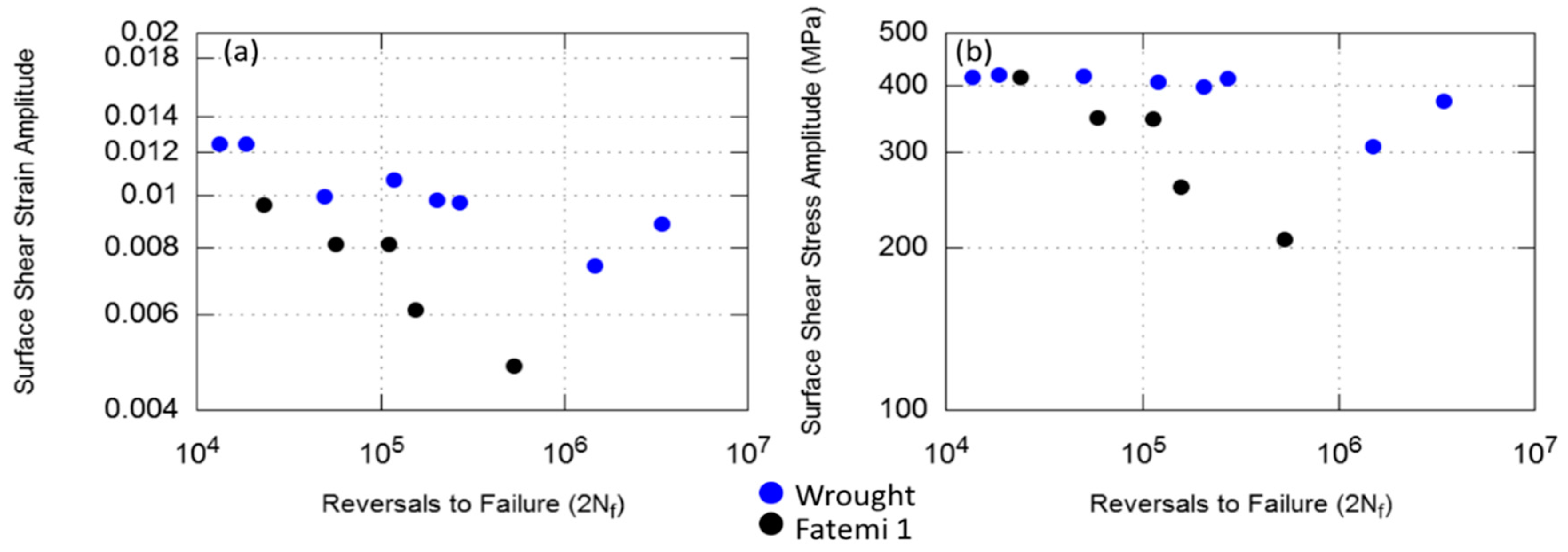
Torsional LCF of SLM Ti-6Al-4V has been given even less attention than axial LCF. Strain-life results of SLM Ti-6Al-4V reported by Fatemi et al. [47] showed that the SLM Ti-6Al-4V had considerably shorter LCF lives than its wrought bimodal counterpart (Figure 8a). However, stress-life results showed that SLM Ti-6Al-4V had a higher shear fatigue strength than the wrought bimodal coupons in LCF (Figure 8b). The reason for this difference could be the higher associated yield stress in α’ martensite dominated coupon, resulting in the tested stress amplitudes being below the macroscopic yield of the SLM coupons, compared to the wrought coupons (which may be in the plastic region). In Table 14 the build orientation, microstructure and porosity are summarised for each of the coupons corresponding to the test results of Figure 8. The corresponding processing parameters used in the manufacturing of the test coupons are provided in Table 15.
Elastoplastic investigation of the SLM coupons to those obtained from a wrought bimodal microstructure was also undertaken by Fatemi et al. [47] at a shear strain amplitude of 2%. The shear stress amplitude progression with cycles compared to the wrought material identified similar softening rates between the two. However, a higher amount of softening was observed in the wrought material, due to the premature fracture in the SLM coupon. Comparison of the mid-life hysteresis loops identified a much narrower hysteresis loop developed from the SLM material than the wrought material, which is consistent with axial elastoplastic results obtained in [71,72,73], associated with the higher cyclic yield in the tested SLM material.
4.5.3. Micro-Mechanism Contribution
The primary and secondary slip planes for titanium alloys are the prism planes and basal planes respectively [77]. The majority of deformation at low temperatures occurs by slip [78]. A difference in the elastoplastic behaviour between the tested ’ martensite microstructure compared to other possible Ti-6Al-4V microstructures is anticipated, due to differences in the micro-mechanism which govern the plastic behaviour. Gil et al. [79] compared the elastoplastic and LCF behaviour of wrought bimodal, lamellar and martensitic microstructures of Ti-6Al-4V. Cyclic softening rates varied between the microstructures due to differences in the micro-mechanisms (that cause cyclic softening). In the bimodal and lamellar microstructure, cyclic softening occurred predominantly due to the existence of mobile dislocations, while in the martensite microstructure, mobile dislocations and induced twinning resulted in cyclic softening. Furthermore, Gil et al. [79] reported that the LCF resistance was higher in the bimodal microstructure, where crack nucleation occurred at grains for low strain amplitude and - interfaces at high strain amplitudes. The lamellar microstructure demonstrated the second highest resistance to LCF. The resistance increased with increasing number of colony boundaries and decreasing grain size, which increased the tortuosity of the crack path. The martensitic microstructure demonstrated the least LCF resistance due to crack propagation occurring along the martensite plate boundaries, reducing the tortuosity of the crack path. A comparison of the LCF and elastoplastic behaviour of an equiaxed and lamellar structure was conducted by Tan et al. [80] using the titanium alloy TC21. This investigation revealed that crack nucleation at LCF occurred easier in the lamellar microstructure than the equiaxed microstructure.
In order to obtain a better understanding of the influence of defects in LCF of AM material, the Åkerfeldt et al. [81] study is considered a helpful source. In this study, the influence of defects on the LCF of Ti-6Al-4V coupons manufactured using laser metal wire disposition has been analysed. In the LCF tests conducted under strain-controlled loading, it was observed that fracture at lower strain amplitudes was dominated by crack initiation due to pores and lack-of-fusion defects in the material, while at high strain amplitudes the cracks initiated on the surface. This was an effect of the stress concentration being higher at the surface of the coupon when subjected to higher strain amplitudes, than the stress concentration at defects and vice-versa, when the material was subjected to lower strain amplitudes. Additionally, the horizontally manufactured coupons had better LCF properties. No failure occurred from cracks initiating at lack-of-fusion defects in horizontal coupons, which is a consequence of the defect being located on a plane parallel to the loading direction. This results in the aspect ratio being lower than that of a round pore, causing a lower stress concentration in the vicinity of the defect [82]. However, lack-of-fusion defects are considerably more dangerous in vertically manufactured coupons, due to the aspect ratio being greater than a round pore, which leads to higher stress concentrations in the vicinity of the lack-of-fusion defect. Consequently, favourably orientated lack-of-fusion defects can be less detrimental both to HCF and LCF life.
4.6. Multiaxial Fatigue Behaviour
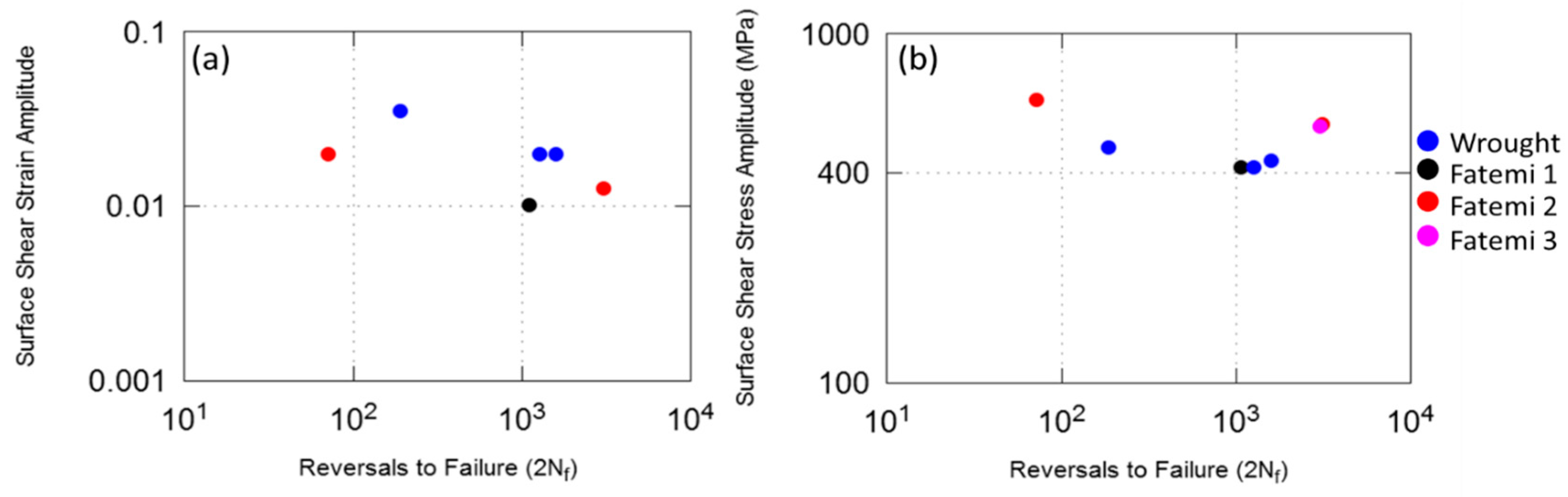
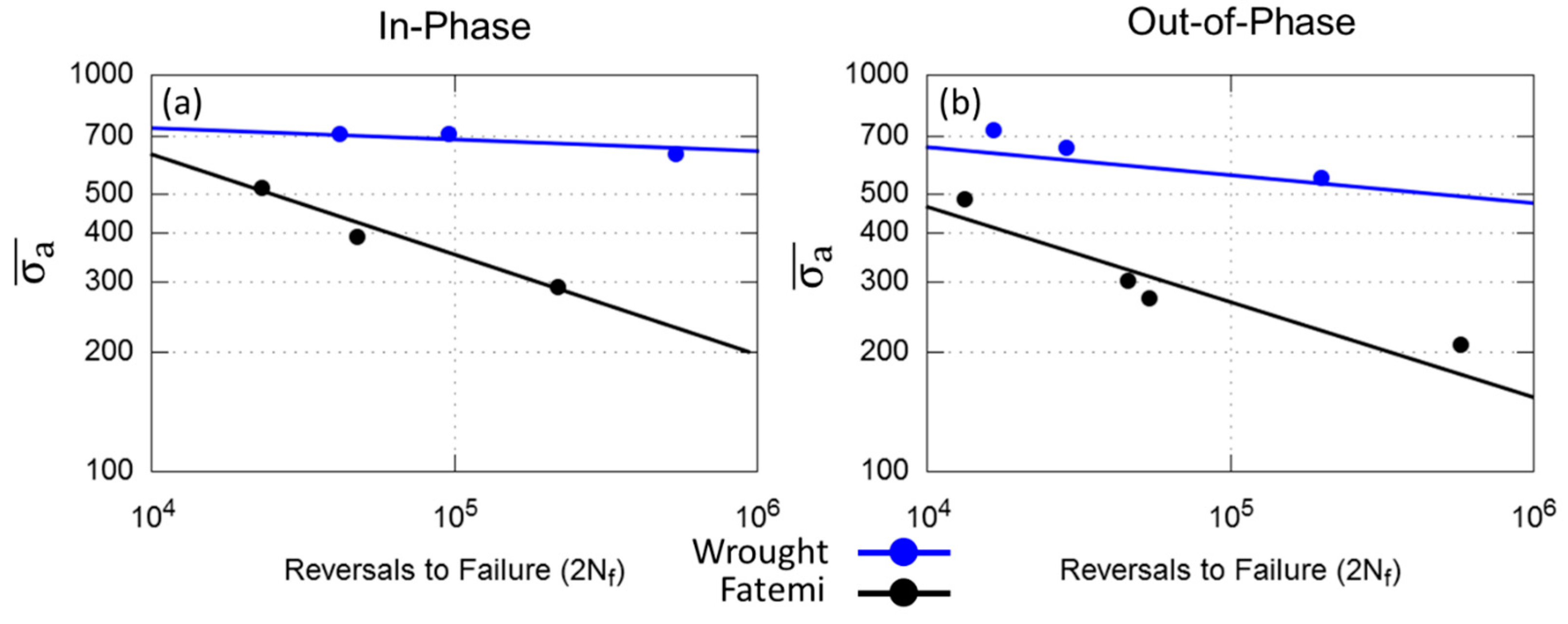
A multiaxial fatigue investigation using both proportional and non-proportional loading on vertically fabricated tubular coupons has been recently published by Fatemi et al. [76]. The coupons have the microstructure characteristics presented in Table 16, manufactured using the process parameters of Table 17. The results of the tested SLM Ti-6Al-4V are summarised in Figure 9, where a comparison to a wrought bimodal microstructure is also presented (using von Mises equivalent stress). It is observed from these results that the multiaxial fatigue resistance of the wrought material is superior to the acicular α’ martensite SLM Ti-6Al-4V for both in-phase and out-of-phase loading conditions.
Micro-Mechanism Contribution
As observed in the research study performed by Fatemi et al. [76], all failures of the SLM coupons occurred on the maximum principal stress plane. This is an expected path for a brittle metal, which is based on both the understanding that acicular α’ martensite microstructures typically have lower ductility than wrought bimodal Ti-6Al-4V and the monotonic test results obtained in this investigation. The complexity of the SLM microstructure presents some concerns with respect to how the crack propagates during both proportional and non-proportional loading. This is further complicated by non-proportional loading, since the principal stress and strain axes rotate during cycling, which not only actives more slip planes [83] but can also result in defects having an even greater influence than they would have in proportional loading. Moreover, the defects present in the material are likely to result in localised stress concentrations, causing shear stresses to promote slip and, therefore, lead to crack nucleation. Thus, it is anticipated that the defects within the material will have an effect on the plane at which the cracks initiate. The interaction of the defects and the layers with the progressive crack propagation will also influence the plane on which the crack propagates until the occurrence of failure. Further test data analysis is considered very important to explore the influence of porosity, the orientation of lack-of-fusion defects and build layer direction on the orientation of the crack propagation plane (critical plane). This information will be of value in the potential use of techniques that can determine the orientation of the critical plane, e.g., Maximum Damage Method (MDM) [84] and Maximum Variance Method [85].
Closer examination of the possible Ti-6Al-4V microstructure in multiaxial fatigue conditions is also an unexplored area requiring attention, especially when this material is used in complex geometry structures and parts prone to HCF. Other than the SLM acicular α’ martensite microstructure investigation by Fatemi et al. [77], Ti-6Al-4V multiaxial fatigue investigations have considered mainly the wrought bimodal Ti-6Al-4V microstructure [83,86,87,88]. An understanding of the microstructural influence on the critical plane orientation is particularly important in the development of a fatigue resistant microstructure, since the underlying microstructure can have a significant influence over the fatigue fracture plane characteristic of the material [89]. Therefore, improving the component’s resistance to multiaxial fatigue is vital to consider when tailoring the microstructure during the SLM process.
5. Conclusions
The review of the published SLM Ti-6Al-4V literature has offered a valuable insight into the current knowledge surrounding the influence of microstructure, defects and residual stresses on the monotonic tensile, HCF, LCF, fracture mechanisms and multiaxial fatigue. An overview of the influence of the different combination of possible phases of Ti-6Al-4V, achieved through SLM on monotonic properties, was provided. In conjunction to this, the microstructure and defect influence on monotonic yield stress and ductility was also summarised and critically commented and assessed. From the overall examination, a consolidated understanding has been developed around these matters, which can inform future research efforts.
An overview of the current HCF behaviour of SLM Ti-6Al-4V has demonstrated that a significant amount of research has been undertaken with respect to the α’ martensite dominated microsructure. However, it seems that less attention has been paid to the possible lamellar (α + β) microstructure. During the crack nucleation stage, finer microstructures are favoured due to a lower quantity of long slip bands, therefore, less irreversible slip leading to fewer nucleation sites. Of particular note is that the extent of defects in the material is likely to affect the crack nucleation stage, due to stress raisers in the vicinity of defects, which influence the rate at which slip is activated. Consequently, the crack growth behaviour of the material becomes increasingly important to consider, as per the increased rate and presence of crack nucleation and microstructurally-small crack growth. SLM crack growth studies have been focused on α’ martensite microstructure. Nevertheless, more favourable microstructures to crack growth have been shown to be bimodal and lamellar microstructures. In order to obtain a deeper understanding on the influence of grain boundaries and layer orientation, in conjunction with a lamellar microstructure on crack growth, the work of Galarraga et al. [55] on EBM-manufactured material has been reviewed. Based on the results arising from this study and the understanding around the effect of SLM-manufactured material build orientation, it can be concluded that it is important crack growth occurs perpendicular to the build layers and, if possible, orientated in the same direction as the elongated grains. Obtaining both of these microstructure features is expected to aid in the crack deflection and reduce the growth rate. Orientating the layers parallel to the load direction will most likely reduce the influence of lack-of-fusion defects on crack nucleation, a result of lower aspect ratio and subsequent localised stress concentration.
Acicular α’ martensite microstructures have also been the primary focus of studies dealing with the elastoplastic and LCF behaviour of SLM Ti-6Al-4V. Further investigations have to be undertaken to enhance our knowledge of the influence that SLM defects may have on LCF resistance of not only acicular α’ martensite but also of the possible lamellar microstructures. An extensive review of the wrought Ti-6Al-4V literature, as well as material obtained through alternate AM fabrication methods, signified the potential improvement to LCF of SLM Ti-6A-4V with a lamellar structure. Moreover, it reiterated the importance of the axial LCF loading direction being parallel to build layers as way to improve fatigue resistance.
Very limited research efforts have been made so far in the examination of multiaxial fatigue examination of AM metals. Of particular importance is considered to be the investigation of the influence of build layers and defects on the plane of crack initiation and propagation. Furthermore, the microstructure contribution to multiaxial fatigue failure has to be explored, especially in relation to lamellar microstructures. A clear understanding of how the crack propagates through different Ti-6Al-4V microstructures will assist in achieving more suitable design for SLM fabricated parts, through an informed selection of microstructures which can mitigate crack propagation and ultimately improve the fatigue life of the structure. Additionally, obtaining more details on the plane orientations that are more susceptible to damage and developing and testing methods of predicting these orientations can be very assistive for design purposes. As proposed by Yadollahi and Shamsaei [54], weaker planes can be aligned with areas expecting lower loads, which will improve the multiaxial fatigue resistance of the material.
An important concept introduced by this review is the idea of using the knowledge of the material such as combination of phases, grain orientation and morphology, the influence of build layer orientation, as well as the influence of defects, to optimise the design and manufacture of components. With the advancement in the understanding of the influence of these microstructural features on the mechanical behaviour of the material, AM offers the unique ability to manipulate these microstructural features in situ, and therefore providing an additional layer to the design process through the inclusion of microstructural design to achieve desired mechanical properties, not only for Ti-6Al-4V but for other materials. This review attempts to highlight the potential of this direction for AM, so future research can be more meticulous in experimental planning and results reporting particularly with respect to the specimen processing conditions and subsequent microstructure. Therefore, reporting of the results obtained from SLM fabricated Ti-6Al-4V should at least include:
- SLM processing parameters;
- Microstructural information, including phases present and size;
- Porosity;
- Location on the build platform;
- Whether it was a single or multiple build;
- Scanning strategy.
Due to the influence of these fabrication details on the behaviour of the material, providing this information shall offer considerably more value to the results currently being reported by most researchers in the open literature. This will assist in building a database for SLM Ti-6Al-4V, which can be referred to in the design of components, particularly in the optimisation and tailoring design of microstructure.
This wide review on SLM fabricated Ti-6Al-4V and the supporting analysis from published Ti-6Al-4V research, for both conventional manufacturing and alternate AM methods, offers a comprehensive guide towards understanding how the microstructure, build orientation, defect percentage can be manipulated and applied in the development of fatigue resistance materials. Also, this review acts as a map identifying research gaps in this field and how further investigation is able to improve this ever-growing database of knowledge.
Acknowledgments
The support received from the RMIT University Higher Degree by Research Publications Grant (HDRPG) is acknowledged.
Author Contributions
Dylan Agius conceived the review; all authors contributed to the data collection, analysis and comments; all authors wrote the paper.
Conflicts of Interest
The authors declare no conflict of interest.
References
- Murr, L.E.; Quinones, S.A.; Gaytan, S.M.; Lopez, M.I.; Rodela, A.; Martinez, E.Y.; Hernandez, D.H.; Martinez, E.; Medina, F.; Wicker, R.B. Microstructure and mechanical behavior of Ti-6Al-4V produced by rapid-layer manufacturing, for biomedical applications. J. Mech. Behav. Biomed. Mater. 2009, 2, 20–32. [Google Scholar] [CrossRef] [PubMed]
- Kürnsteiner, P.; Wilms, M.B.; Weisheit, A.; Barriobero-Vila, P.; Jägle, E.A.; Raabe, D. Massive nanoprecipitation in an Fe-19Ni-xAl maraging steel triggered by the intrinsic heat treatment during laser metal deposition. Acta Mater. 2017, 129, 52–60. [Google Scholar] [CrossRef]
- Morton, P.A.; Mireles, J.; Mendoza, H.; Cordero, P.M.; Benedict, M.; Wicker, R.B. Enhancement of Low-Cycle Fatigue Performance From Tailored Microstructures Enabled by Electron Beam Melting Additive Manufacturing Technology. J. Mech. Des. 2015, 137, 111412–111414. [Google Scholar] [CrossRef]
- Vrancken, B.; Thijs, L.; Kruth, J.P.; Van Humbeeck, J. Heat treatment of Ti6Al4V produced by Selective Laser Melting: Microstructure and mechanical properties. J. Alloys Compd. 2012, 541, 177–185. [Google Scholar] [CrossRef]
- Chen, L.Y.; Huang, J.C.; Lin, C.H.; Pan, C.T.; Chen, S.Y.; Yang, T.L.; Lin, D.Y.; Lin, H.K.; Jang, J.S.C. Anisotropic response of Ti-6Al-4V alloy fabricated by 3D printing selective laser melting. Mater. Sci. Eng. A 2017, 682, 389–395. [Google Scholar] [CrossRef]
- Qiu, C.; Adkins, N.J.E.; Attallah, M.M. Microstructure and tensile properties of selectively laser-melted and of HIPed laser-melted Ti-6Al-4V. Mater. Sci. Eng. A 2013, 578, 230–239. [Google Scholar] [CrossRef]
- Shi, X.; Ma, S.; Liu, C.; Wu, Q.; Lu, J.; Liu, Y.; Shi, W. Selective laser melting-wire arc additive manufacturing hybrid fabrication of Ti-6Al-4V alloy: Microstructure and mechanical properties. Mater. Sci. Eng. A 2017, 684, 196–204. [Google Scholar] [CrossRef]
- Simonelli, M.; Tse, Y.Y.; Tuck, C. Effect of the build orientation on the mechanical properties and fracture modes of SLM Ti-6Al-4V. Mater. Sci. Eng. A 2014, 616, 1–11. [Google Scholar] [CrossRef]
- Xu, W.; Lui, E.W.; Pateras, A.; Qian, M.; Brandt, M. In situ tailoring microstructure in additively manufactured Ti-6Al-4V for superior mechanical performance. Acta Mater. 2017, 125, 390–400. [Google Scholar] [CrossRef]
- Ahmed, T.; Rack, H.J. Phase transformations during cooling in α + β titanium alloys. Mater. Sci. Eng. A 1998, 243, 206–211. [Google Scholar] [CrossRef]
- Al-Bermani, S.S.; Blackmore, M.L.; Zhang, W.; Todd, I. The origin of microstructural diversity, texture, and mechanical properties in electron beam melted Ti-6Al-4V. Metall. Mater. Trans. A Phys. Metall. Mater. Sci. 2010, 41, 3422–3434. [Google Scholar] [CrossRef]
- Yang, J.; Yu, H.; Yin, J.; Gao, M.; Wang, Z.; Zeng, X. Formation and control of martensite in Ti-6Al-4V alloy produced by selective laser melting. Mater. Des. 2016, 108, 308–318. [Google Scholar] [CrossRef]
- Yang, J.; Han, J.; Yu, H.; Yin, J.; Gao, M.; Wang, Z.; Zeng, X. Role of molten pool mode on formability, microstructure and mechanical properties of selective laser melted Ti-6Al-4V alloy. Mater. Des. 2016, 110, 558–570. [Google Scholar] [CrossRef]
- Lütjering, G. Influence of processing on microstructure and mechanical properties of (α + β) titanium alloys. Mater. Sci. Eng. A 1998, 243, 32–45. [Google Scholar] [CrossRef]
- Xu, W.; Brandt, M.; Sun, S.; Elambasseril, J.; Liu, Q.; Latham, K.; Xia, K.; Qian, M. Additive manufacturing of strong and ductile Ti-6Al-4V by selective laser melting via in situ martensite decomposition. Acta Mater. 2015, 85, 74–84. [Google Scholar] [CrossRef]
- Xu, W.; Sun, S.; Elambasseril, J.; Liu, Q.; Brandt, M.; Qian, M. Ti-6Al-4V Additively Manufactured by Selective Laser Melting with Superior Mechanical Properties. JOM 2015, 67, 668–673. [Google Scholar] [CrossRef]
- Simonelli, M.; Tse, Y.Y.; Tuck, C. The formation of α + β microstructure in as-fabricated selective laser melting of Ti-6Al-4V. J. Mater. Res. 2014, 29, 2028–2035. [Google Scholar] [CrossRef]
- Ali, H.; Ma, L.; Ghadbeigi, H.; Mumtaz, K. In situ residual stress reduction, martensitic decomposition and mechanical properties enhancement through high temperature powder bed pre-heating of Selective Laser Melted Ti6Al4V. Mater. Sci. Eng. A 2017, 695, 211–220. [Google Scholar] [CrossRef]
- Ter Haar, G.M.; Becker, T.H.; Blaine, D.C. Influence of heat treatments on the microstructure and tensile behaviour of selective laser melting-produced TI-6AL-4V parts. S. Afr. J. Ind. Eng. 2016, 27, 174–183. [Google Scholar] [CrossRef]
- Vilaro, T.; Colin, C.; Bartout, J.D. As-fabricated and heat-treated microstructures of the Ti-6Al-4V alloy processed by selective laser melting. Metall. Mater. Trans. A Phys. Metall. Mater. Sci. 2011, 42, 3190–3199. [Google Scholar] [CrossRef]
- Barriobero-Vila, P.; Gussone, J.; Haubrich, J.; Sandlöbes, S.; Da Silva, J.C.; Cloetens, P.; Schell, N.; Requena, G. Inducing stable α + β microstructures during selective laser melting of Ti-6Al-4V using intensified intrinsic heat treatments. Materials 2017, 10, 268. [Google Scholar] [CrossRef] [PubMed]
- Kasperovich, G.; Haubrich, J.; Gussone, J.; Requena, G. Correlation between porosity and processing parameters in TiAl6V4 produced by selective laser melting. Mater. Des. 2016, 105, 160–170. [Google Scholar] [CrossRef]
- Grasso, M.; Colosimo, B.M. Process defects and in situ monitoring methods in metal powder bed fusion: A review. Meas. Sci. Technol. 2017, 28, 044005. [Google Scholar] [CrossRef]
- Gong, H.; Rafi, K.; Karthik, N.; Starr, T.; Stucker, B. Defect Morphology in Ti-6Al-4V Parts Fabricated by Selective Laser Melting and Electron Beam Melting. In Proceedings of the 24th Annual International Solid Freeform Fabrication Symposium—An Additive Manufacturing Conference, Austin, TX, USA, 12–14 August 2013; pp. 12–14. [Google Scholar]
- Panwisawas, C.; Qiu, C.L.; Sovani, Y.; Brooks, J.W.; Attallah, M.M.; Basoalto, H.C. On the role of thermal fluid dynamics into the evolution of porosity during selective laser melting. Scr. Mater. 2015, 105, 14–17. [Google Scholar] [CrossRef]
- Kasperovich, G.; Hausmann, J. Improvement of fatigue resistance and ductility of TiAl6V4 processed by selective laser melting. J. Mater. Process. Technol. 2015, 220, 202–214. [Google Scholar] [CrossRef]
- Kong, C.-J.; Tuck, C.J.; Ashcroft, I.A.; Wildman, R.D.; Hague, R. High density Ti6Al4V via SLM processing: Microstructure and mechanical properties. In Proceedings of the 22nd Annual International Solid Freeform Fabrication: An Additive Manufacturing Conference, Austin, TX, USA, 8–10 August 2011; University of Texas: Austin, TX, USA, 2011; pp. 475–483. [Google Scholar]
- Ferrar, B.; Mullen, L.; Jones, E.; Stamp, R.; Sutcliffe, C.J. Gas flow effects on selective laser melting (SLM) manufacturing performance. J. Mater. Process. Technol. 2012, 212, 355–364. [Google Scholar] [CrossRef]
- Ladewig, A.; Schlick, G.; Fisser, M.; Schulze, V.; Glatzel, U. Influence of the shielding gas flow on the removal of process by-products in the selective laser melting process. Addit. Manuf. 2016, 10, 1–9. [Google Scholar] [CrossRef]
- Mercelis, P.; Kruth, J.P. Residual stresses in selective laser sintering and selective laser melting. Rapid Prototyp. J. 2006, 12, 254–265. [Google Scholar] [CrossRef]
- Knowles, C.R.; Becker, T.H.; Tait, R.B. Residual stress measurements and structural integrity implications for selective laser melted Ti-6Al-4V. S. Afr. J. Ind. Eng. 2012, 23, 119–129. [Google Scholar] [CrossRef]
- Leuders, S.; Thöne, M.; Riemer, A.; Niendorf, T.; Tröster, T.; Richard, H.A.; Maier, H.J. On the mechanical behaviour of titanium alloy TiAl6V4 manufactured by selective laser melting: Fatigue resistance and crack growth performance. Int. J. Fatigue 2013, 48, 300–307. [Google Scholar] [CrossRef]
- Nickel, A.H.; Barnett, D.M.; Prinz, F.B. Thermal stresses and deposition patterns in layered manufacturing. Mater. Sci. Eng. A 2001, 317, 59–64. [Google Scholar] [CrossRef]
- Shiomi, M.; Osakada, K.; Nakamura, K.; Yamashita, T.; Abe, F. Residual Stress within Metallic Model Made by Selective Laser Melting Process. CIRP Ann. 2004, 53, 195–198. [Google Scholar] [CrossRef]
- Klingbeil, N.W.; Beuth, J.L.; Chin, R.K.; Amon, C.H. Measurement and modeling of residual stress-induced warping in direct metal deposition processes. In Proceedings of the 1998 Solid Freeform Fabrication Symposium, Austin, TX, USA, 11–13 August 1998; pp. 367–374. [Google Scholar]
- Casavola, C.; Campanelli, S.L.; Pappalettere, C. Preliminary investigation on distribution of residual stress generated by the selective laser melting process. J. Strain Anal. Eng. Des. 2009, 44, 93–104. [Google Scholar] [CrossRef]
- Masoomi, M.; Thompson, S.M.; Shamsaei, N. Laser powder bed fusion of Ti-6Al-4V parts: Thermal modeling and mechanical implications. Int. J. Mach. Tools Manuf. 2017, 118–119, 73–90. [Google Scholar] [CrossRef]
- Lewandowski, J.J.; Seifi, M. Metal Additive Manufacturing: A Review of Mechanical Properties. Annu. Rev. Mater. Res. 2016, 46, 151–186. [Google Scholar] [CrossRef]
- Tong, J.; Bowen, C.R.; Persson, J.; Plummer, A. Mechanical properties of titanium-based Ti-6Al-4V alloys manufactured by powder bed additive manufacture. Mater. Sci. Technol. 2017, 33, 138–148. [Google Scholar] [CrossRef]
- Cain, V.; Thijs, L.; Van Humbeeck, J.; Van Hooreweder, B.; Knutsen, R. Crack propagation and fracture toughness of Ti6Al4V alloy produced by selective laser melting. Addit. Manuf. 2015, 5, 68–76. [Google Scholar] [CrossRef]
- Facchini, L.; Magalini, E.; Robotti, P.; Molinari, A.; Höges, S.; Wissenbach, K. Ductility of a Ti-6Al-4V alloy produced by selective laser melting of prealloyed powders. Rapid Prototyp. J. 2010, 16, 450–459. [Google Scholar] [CrossRef]
- Gong, H.; Rafi, K.; Gu, H.; Janaki Ram, G.D.; Starr, T.; Stucker, B. Influence of defects on mechanical properties of Ti-6Al-4 V components produced by selective laser melting and electron beam melting. Mater. Des. 2015, 86, 545–554. [Google Scholar] [CrossRef]
- Leuders, S.; Lieneke, T.; Lammers, S.; Tröster, T.; Niendorf, T. On the fatigue properties of metals manufactured by selective laser melting—The role of ductility. J. Mater. Res. 2014, 29, 1911–1919. [Google Scholar] [CrossRef]
- Mertens, A.; Reginster, S.; Paydas, H.; Contrepois, Q.; Dormal, T.; Lemaire, O.; Lecomte-Beckers, J. Mechanical properties of alloy Ti-6Al-4V and of stainless steel 316L processed by selective laser melting: Influence of out-of-equilibrium microstructures. Powder Metall. 2014, 57, 184–189. [Google Scholar] [CrossRef]
- Rafi, H.K.; Karthik, N.V.; Gong, H.; Starr, T.L.; Stucker, B.E. Microstructures and mechanical properties of Ti6Al4V parts fabricated by selective laser melting and electron beam melting. J. Mater. Eng. Perform. 2013, 22, 3872–3883. [Google Scholar] [CrossRef]
- Hollander, D.A.; von Walter, M.; Wirtz, T.; Sellei, R.; Schmidt-Rohlfing, B.; Paar, O.; Erli, H.-J. Structural, mechanical and in vitro characterization of individually structured Ti-6Al-4V produced by direct laser forming. Biomaterials 2006, 27, 955–963. [Google Scholar] [CrossRef] [PubMed]
- Fatemi, A.; Molaei, R.; Sharifimehr, S.; Shamsaei, N.; Phan, N. Torsional fatigue behavior of wrought and additive manufactured Ti-6Al-4V by powder bed fusion including surface finish effect. Int. J. Fatigue 2017, 99, 187–201. [Google Scholar] [CrossRef]
- Huang, Q.; Hu, N.; Yang, X.; Zhang, R.; Feng, Q. Microstructure and inclusion of Ti-6Al-4V fabricated by selective laser melting. Front. Mater. Sci. 2016, 10, 428–431. [Google Scholar] [CrossRef]
- Hennig, R.G.; Trinkle, D.R.; Bouchet, J.; Srinivasan, S.G.; Albers, R.C.; Wilkins, J.W. Impurities block the α to ω martensitic transformation in titanium. Nat. Mater. 2005, 4, 129–133. [Google Scholar] [CrossRef] [PubMed]
- Banerjee, D.; Williams, J.C. Perspectives on Titanium Science and Technology. Acta Mater. 2013, 61, 844–879. [Google Scholar] [CrossRef]
- Yang, J.; Yu, H.; Wang, Z.; Zeng, X. Effect of crystallographic orientation on mechanical anisotropy of selective laser melted Ti-6Al-4V alloy. Mater. Charact. 2017, 127, 137–145. [Google Scholar] [CrossRef]
- Van Hooreweder, B.; Moens, D.; Boonen, R.; Kruth, J.P.; Sas, P. Analysis of fracture toughness and crack propagation of Ti6Al4V produced by selective laser melting. Adv. Eng. Mater. 2012, 14, 92–97. [Google Scholar] [CrossRef]
- Edwards, P.; Ramulu, M. Effect of build direction on the fracture toughness and fatigue crack growth in selective laser melted Ti-6Al-4 V. Fatigue Fract. Eng. Mater. Struct. 2015, 38, 1228–1236. [Google Scholar] [CrossRef]
- Yadollahi, A.; Shamsaei, N. Additive manufacturing of fatigue resistant materials: Challenges and opportunities. Int. J. Fatigue 2017, 98, 14–31. [Google Scholar] [CrossRef]
- Galarraga, H.; Warren, R.J.; Lados, D.A.; Dehoff, R.R.; Kirka, M.M. Fatigue crack growth mechanisms at the microstructure scale in as-fabricated and heat treated Ti-6Al-4V ELI manufactured by electron beam melting (EBM). Eng. Fract. Mech. 2017, 176, 263–280. [Google Scholar] [CrossRef]
- Zhai, Y.; Lados, D.A.; Brown, E.J.; Vigilante, G.N. Fatigue crack growth behavior and microstructural mechanisms in Ti-6Al-4V manufactured by laser engineered net shaping. Int. J. Fatigue 2016, 93, 51–63. [Google Scholar] [CrossRef]
- Nalla, R.K.; Ritchie, R.O.; Boyce, B.L.; Campbell, J.P.; Peters, J.O. Influence of microstructure on high-cycle fatigue of Ti-6Al-4V: Bimodal vs. lamellar structures. Metall. Mater. Trans. A 2002, 33, 899–918. [Google Scholar] [CrossRef]
- Tao, J.; Hu, S.; Ji, L. Effect of micromorphology at the fatigue crack tip on the crack growth in electron beam welded Ti-6Al-4V joint. Mater. Charact. 2016, 120, 185–194. [Google Scholar] [CrossRef]
- Li, P.; Warner, D.H.; Fatemi, A.; Phan, N. Critical assessment of the fatigue performance of additively manufactured Ti-6Al-4V and perspective for future research. Int. J. Fatigue 2016, 85, 130–143. [Google Scholar] [CrossRef]
- Eric, W.; Claus, E.; Shafaqat, S.; Frank, W. High cycle fatigue (HCF) performance of Ti-6Al-4V alloy processed by selective laser melting. Adv. Mater. Res. 2013, 816–817, 134–139. [Google Scholar] [CrossRef]
- Rafi, H.K.; Starr, T.L.; Stucker, B.E. A comparison of the tensile, fatigue, and fracture behavior of Ti-6Al-4V and 15-5 PH stainless steel parts made by selective laser melting. Int. J. Adv. Manuf. Technol. 2013, 69, 1299–1309. [Google Scholar] [CrossRef]
- Edwards, P.; Ramulu, M. Fatigue performance evaluation of selective laser melted Ti-6Al-4V. Mater. Sci. Eng. A 2014, 598, 327–337. [Google Scholar] [CrossRef]
- Razavi, S.-M.-J.; Ferro, P.; Berto, F. Fatigue Assessment of Ti-6Al-4V Circular Notched Specimens Produced by Selective Laser Melting. Metals 2017, 7, 291. [Google Scholar] [CrossRef]
- Chan, K.S. Roles of microstructure in fatigue crack initiation. Int. J. Fatigue 2010, 32, 1428–1447. [Google Scholar] [CrossRef]
- Fan, J.; McDowell, D.L.; Horstemeyer, M.F.; Gall, K. Cyclic plasticity at pores and inclusions in cast Al-Si alloys. Eng. Fract. Mech. 2003, 70, 1281–1302. [Google Scholar] [CrossRef]
- Yadollahi, A.; Shamsaei, N.; Thompson, S.M.; Elwany, A.; Bian, L. Effects of building orientation and heat treatment on fatigue behavior of selective laser melted 17-4 PH stainless steel. Int. J. Fatigue 2017, 94, 218–235. [Google Scholar] [CrossRef]
- Mall, S.; Namjoshi, S.A.; Porter, W.J. Effects of microstructure on fretting fatigue crack initiation behavior of Ti-6Al-4V. Mater. Sci. Eng. A 2004, 383, 334–340. [Google Scholar] [CrossRef]
- Bantounas, I.; Lindley, T.C.; Rugg, D.; Dye, D. Effect of microtexture on fatigue cracking in Ti-6Al-4V. Acta Mater. 2007, 55, 5655–5665. [Google Scholar] [CrossRef]
- Wu, G.Q.; Shi, C.L.; Sha, W.; Sha, A.X.; Jiang, H.R. Effect of microstructure on the fatigue properties of Ti-6Al-4V titanium alloys. Mater. Des. 2013, 46, 668–674. [Google Scholar] [CrossRef] [Green Version]
- Holmes, J.; Queeney, R.A. Fatigue crack initiation in a porous steel. Powder Metall. 1985, 28, 231–235. [Google Scholar] [CrossRef]
- Kourousis, K.I.; Agius, D.; Wang, C.; Subic, A. Constitutive modeling of additive manufactured Ti-6Al-4V cyclic elastoplastic behaviour. Tech. Mech. 2016, 36, 57–72. [Google Scholar] [CrossRef]
- Phaiboonworachat, A.; Kourousis, K.I. Cyclic elastoplastic behaviour, hardness and microstructural properties of Ti-6Al-4V manufactured through selective laser melting. Int. J. Mater. Eng. Innov. 2016, 7, 80–87. [Google Scholar] [CrossRef]
- Agius, D.; Kourousis, K.I.; Wallbrink, C.; Song, T. Cyclic plasticity and microstructure of as-built SLM Ti-6Al-4V: The effect of build orientation. Mater. Sci. Eng. A 2017, 701, 85–100. [Google Scholar] [CrossRef]
- Dafalias, Y.F.; Kourousis, K.I.; Saridis, G.J. Multiplicative AF kinematic hardening in plasticity. Int. J. Solids Struct. 2008, 45, 2861–2880. [Google Scholar] [CrossRef]
- Gribbin, S.; Bicknell, J.; Jorgensen, L.; Tsukrov, I.; Knezevic, M. Low cycle fatigue behavior of direct metal laser sintered Inconel alloy 718. Int. J. Fatigue 2016, 93, 156–167. [Google Scholar] [CrossRef]
- Fatemi, A.; Molaei, R.; Sharifimehr, S.; Phan, N.; Shamsaei, N. Multiaxial fatigue behavior of wrought and additive manufactured Ti-6Al-4V including surface finish effect. Int. J. Fatigue 2017, 100, 347–366. [Google Scholar] [CrossRef]
- Evans, W.J.; Jones, J.P.; Whittaker, M.T. Texture effects under tension and torsion loading conditions in titanium alloys. Int. J. Fatigue 2005, 27, 1244–1250. [Google Scholar] [CrossRef]
- Kailas, S.V.; Prasad, Y.V.R.K.; Biswas, S.K. Influence of initial texture on the microstructural instabilities during compression of commercial α-Titanium at 25 °C to 400 °C. Metall. Mater. Trans. A 1994, 25, 1425–1434. [Google Scholar] [CrossRef]
- Gil, F.J.; Manero, J.M.; Ginebra, M.P.; Planell, J.A. The effect of cooling rate on the cyclic deformation of β-annealed Ti-6Al-4V. Mater. Sci. Eng. A 2003, 349, 150–155. [Google Scholar] [CrossRef]
- Tan, C.; Li, X.; Sun, Q.; Xiao, L.; Zhao, Y.; Sun, J. Effect of α-phase morphology on low-cycle fatigue behavior of TC21 alloy. Int. J. Fatigue 2015, 75, 1–9. [Google Scholar] [CrossRef]
- Åkerfeldt, P.; Pederson, R.; Antti, M.-L. A fractographic study exploring the relationship between the low cycle fatigue and metallurgical properties of laser metal wire deposited Ti-6Al-4V. Int. J. Fatigue 2016, 87, 245–256. [Google Scholar] [CrossRef]
- Kumar, P.; Ravi Chandran, K.S.; Cao, F.; Koopman, M.; Fang, Z.Z. The Nature of Tensile Ductility as Controlled by Extreme-Sized Pores in Powder Metallurgy Ti-6Al-4V Alloy. Metall. Mater. Trans. A 2016, 47, 2150–2161. [Google Scholar] [CrossRef]
- Nakamura, H.; Takanashi, M.; Itoh, T.; Wu, M.; Shimizu, Y. Fatigue crack initiation and growth behavior of Ti-6Al-4V under non-proportional multiaxial loading. Int. J. Fatigue 2011, 33, 842–848. [Google Scholar] [CrossRef]
- Bannantine, J.A.; Socie, D.F. A multiaxial fatigue life estimation technique. In Advances in Fatigue Lifetime Predictive Techniques; ASTM STP 1122; Mitchell, M.R., Landgraf, R.W., Eds.; American Society for Testing and Materials: Philadelphia, PA, USA, 1992; pp. 249–275. [Google Scholar]
- Macha, E. Simulation investigations of the position of Fatigue Fracture Plane in materials with biaxial loads. Materialwissenschaft Werkstofftechnik 1989, 20, 132–136. [Google Scholar] [CrossRef]
- Wu, M.; Itoh, T.; Shimizu, Y.; Nakamura, H.; Takanashi, M. Low cycle fatigue life of Ti-6Al-4V alloy under non-proportional loading. Int. J. Fatigue 2012, 44, 14–20. [Google Scholar] [CrossRef]
- Morishita, T.; Itoh, T.; Sakane, M.; Nakamura, H.; Takanashi, M. Multiaxial fatigue property of Ti-6Al-4V using hollow cylinder specimen under push-pull and cyclic inner pressure loading. Int. J. Fatigue 2016, 87, 370–380. [Google Scholar] [CrossRef]
- Berto, F.; Campagnolo, A.; Lazzarin, P. Fatigue strength of severely notched specimens made of Ti-6Al-4V under multiaxial loading. Fatigue Fract. Eng. Mater. Struct. 2015, 38, 503–517. [Google Scholar] [CrossRef]
- Marciniak, Z.; Rozumek, D.; Macha, E. Verification of fatigue critical plane position according to variance and damage accumulation methods under multiaxial loading. Int. J. Fatigue 2014, 58, 84–93. [Google Scholar] [CrossRef]
Figure 1.
Laser scanning strategies commonly reported in the literature.
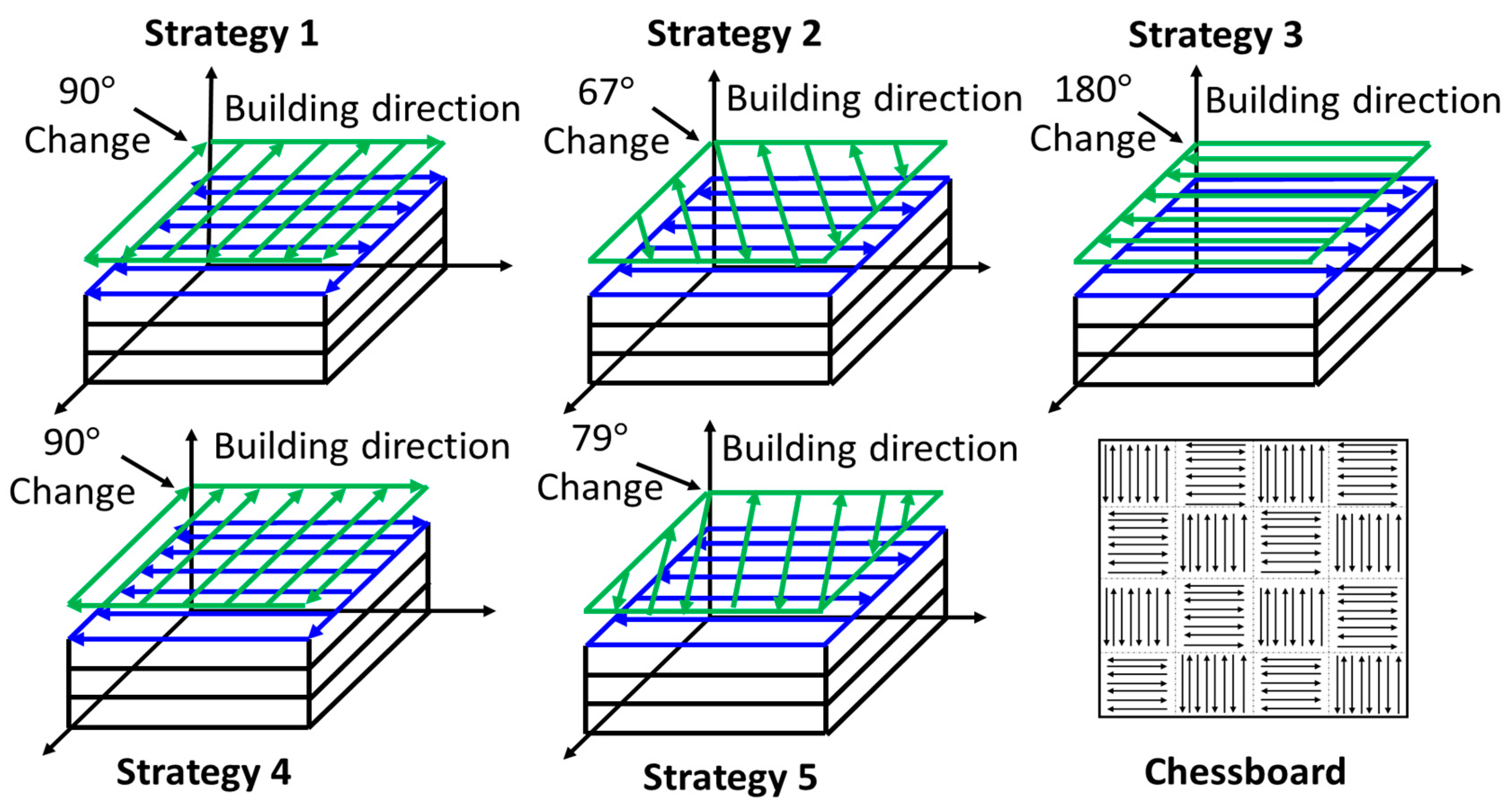
Figure 2.
Flat and cylindrical tensile and fatigue test coupons used in axial tests with corresponding reference labels indicating the build orientation.
Figure 2.
Flat and cylindrical tensile and fatigue test coupons used in axial tests with corresponding reference labels indicating the build orientation.
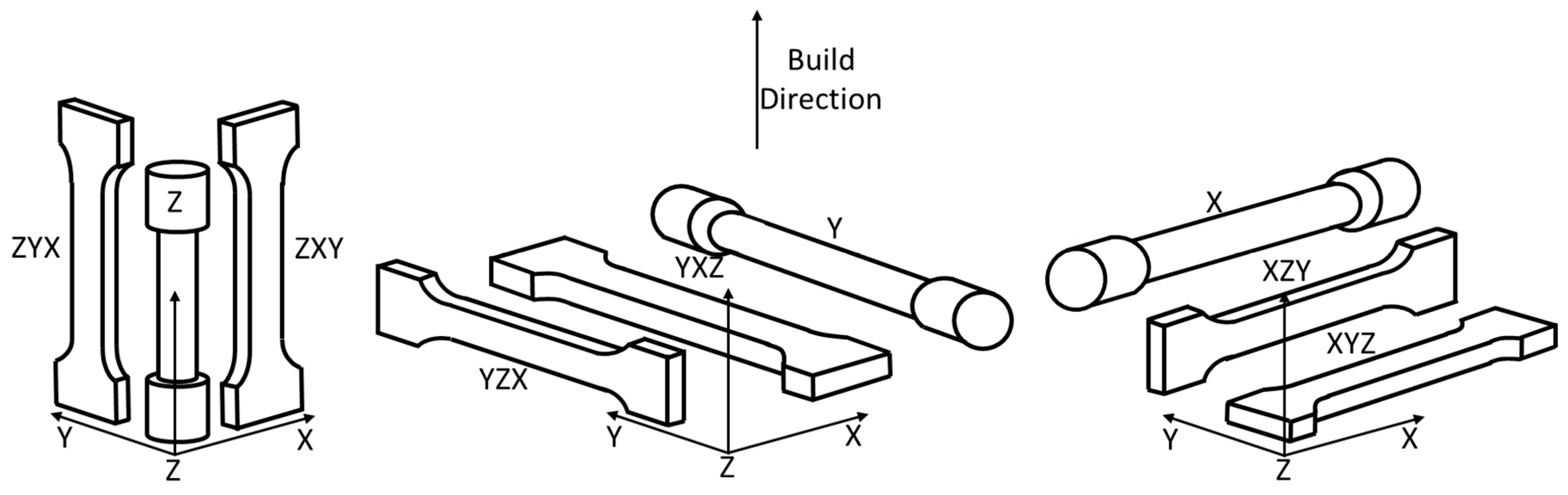
Figure 3.
Compact-tensile (CT) coupon build orientations and corresponding build orientation reference label.
Figure 3.
Compact-tensile (CT) coupon build orientations and corresponding build orientation reference label.
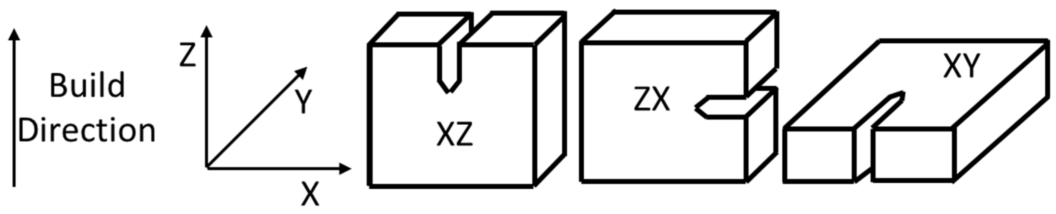
Figure 4.
Comparison of the yield strength and elongation of SLM Ti-6Al-4V coupons of different microstructure, build orientation, and porosity levels obtained from the literature listed in Table 1 (circle points represent an α’ martensite coupons and square points represent a lamellar (α + β) microstructure).
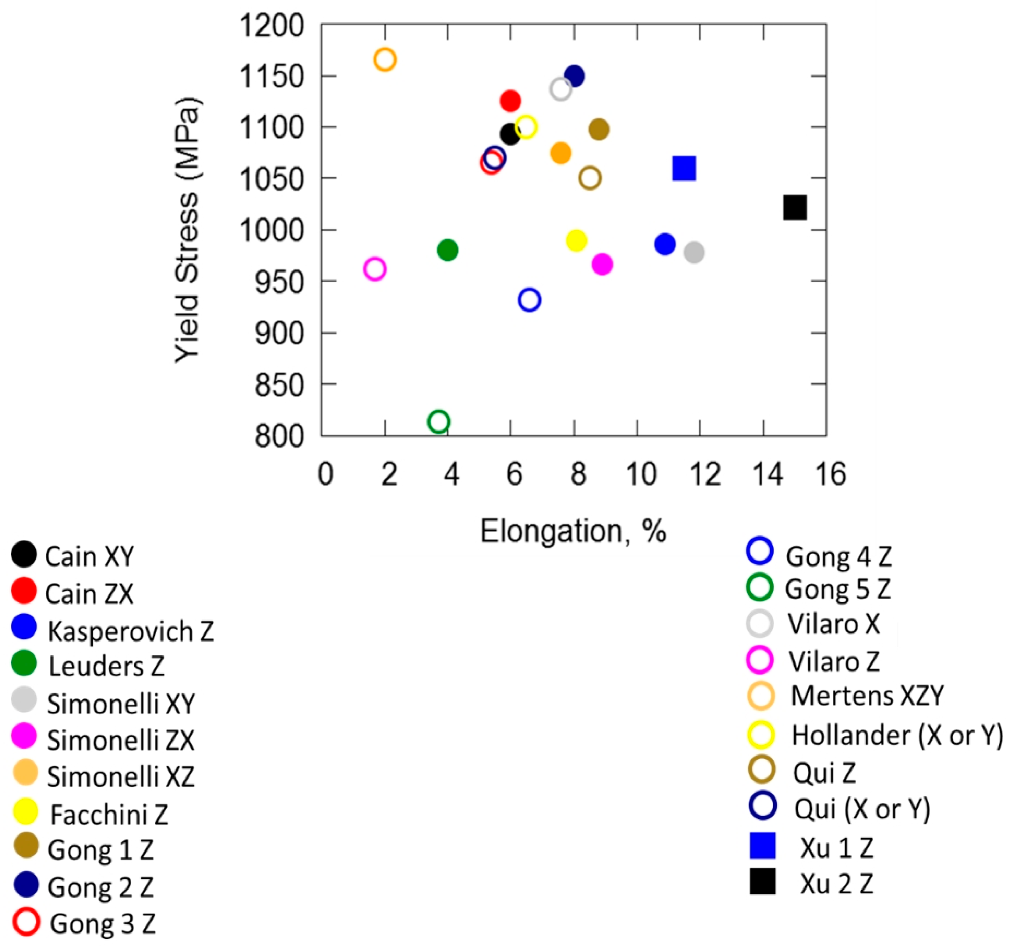
Figure 5.
Comparison of the fatigue crack growth rate (FCGR), da/dN versus stress intensity factor range dK, in the Paris-region for various results obtained from the literature.
Figure 5.
Comparison of the fatigue crack growth rate (FCGR), da/dN versus stress intensity factor range dK, in the Paris-region for various results obtained from the literature.

Figure 6.
Axial high cycle fatigue (HCF) performance of SLM Ti-6Al-4V for machined coupons, where cycle points are α’ martensite microstructures and square points are lamellar (α + β). Results are displayed across two chart areas to prevent cluttering of results and improve visualisation. Lines of best fit are also included to help with visualisation of results.

Figure 7.
Fully reversed torsional high cycle fatigue (HCF) test results in (a) shear strain-controlled tests (b) shear stress-controlled tests (adopted from [47]).
Figure 7.
Fully reversed torsional high cycle fatigue (HCF) test results in (a) shear strain-controlled tests (b) shear stress-controlled tests (adopted from [47]).

Figure 8.
Fully reversed torsional low cycle fatigue (LCF) test results in (a) shear strain-controlled tests (b) shear stress-controlled tests (data obtained and adapted from [47] and [76]).

Figure 9.
Multiaxial axial torsion loading results comparison between SLM Ti-6Al-4V and wrought Ti-6Al-4V for (a) in-phase loading and (b) out-of-phase loading, compared using von Mises equivalent stress, for tests conducted by Fatemi et al. [76].
Figure 9.
Multiaxial axial torsion loading results comparison between SLM Ti-6Al-4V and wrought Ti-6Al-4V for (a) in-phase loading and (b) out-of-phase loading, compared using von Mises equivalent stress, for tests conducted by Fatemi et al. [76].


Table 1.
Material features of the coupons used in monotonic tensile tests (summarised literature).
| Label | Reference | Build Orientation | Microstructure | Porosity (vol %) (Compared to Standard Density of Ti-6Al-4V 4.43 ) | Post Treatment |
|---|---|---|---|---|---|
| Cain | [40] | Flat XY, ZX | martensite | <1 | None |
| Kasperovich | [26] | Cylindrical Z | martensite | 0.077 | None |
| Leuders | [43] | Cylindrical Z | martensite | NR | None |
| Simonelli | [8] | Flat XY, ZX, XZ | martensite | NR | None |
| Facchini | [41] | Flat Z | martensite | 0.3 | None |
| Gong 1 | [42] | Cylindrical Z | martensite | 0.45 | None |
| Gong 2 | 1.37 | ||||
| Gong 3 | 5.23 | ||||
| Gong 4 | 1.37 | ||||
| Gong 5 | 5.48 | ||||
| Vilaro | [20] | Flat (X or Y), Z | martensite | <1 | None |
| Mertens | [44] | Flat XZY | martensite | <0.5 | None |
| Hollander | [46] | Cylindrical (X or Y) | NR | <0.5 | None |
| Qui | [6] | Cylindrical Z, (X or Y) | martensite | <0.1 | None |
| Xu 1 | [9] | Cylindrical Z | Coarse lamellar ( + ) | NR | None |
| Xu 2 | [15] | Cylindrical Z | Ultrafine lamellar ( + ) | <0.5 | None |
NR = Not Recorded.
Table 2.
SLM parameters used in coupon manufacture for each version of Ti-6Al-4V used in monotonic tensile results (summarised literature).
Table 2.
SLM parameters used in coupon manufacture for each version of Ti-6Al-4V used in monotonic tensile results (summarised literature).
| Label | Reference | Laser Power (W) | Scan Speed (mm/s) | Hatch Spacing (m) | Layer Thickness (m) | Baseplate Temperature (°C) | Scanning Strategy | Multiple or Single Build |
|---|---|---|---|---|---|---|---|---|
| Cain 1 | [40] | NR | NR | NR | NR | NR | 1 | Single |
| Kasperovich | [26] | 200 | 1250 | NR | 40 | NR | NR | Multiple |
| Leuders | [43] | 400 | NR | NR | 30 | NR | NR | NR |
| Simonelli | [8] | 157 | 225 | 100 | 50 | NR | 2 | Multiple |
| Facchini | [41] | 195 | 225 | NR | NR | NR | NR | Multiple |
| Gong 1 | [42] | 120 | 960 | 100 | 30 | NR | NR | Multiple |
| Gong 2 | 540 | |||||||
| Gong 3 | 400 | |||||||
| Gong 4 | 1260 | |||||||
| Gong 5 | 1500 | |||||||
| Vilaro | [20] | 160 | 600 | 200 | 40 | 500 | Strategy 4 in a 5 × 5 region | NR |
| Mertens | [44] | 175 | 710 | 120 | 30 | NR | Strategy 5 in chessboard pattern | NR |
| Hollander | [46] | NR | NR | NR | NR | NR | NR | NR |
| Qui | [6] | 150–200 | 800–1500 | 75 | 20 | NR | Chessboard | Multiple |
| Xu 1 | [9] | 375 | 686–1029 | 120 | 60 | 200 | Chessboard | Multiple |
| Xu 2 | [15] | 175–375 | 686–1029 | 120 | 30-90 | 200 | NR | Multiple |
NR = Not Recorded.
Table 3.
Monotonic torsion results for SLM Ti-6Al-4V obtained from [47].
Table 3.
Monotonic torsion results for SLM Ti-6Al-4V obtained from [47].
| Coupon | Shear Modulus (GPa) | Shear Yield Strength (MPa) | Shear Ultimate Strength (MPa) | Shear Fracture Strain (%) |
|---|---|---|---|---|
| Wrought | 42 | 523 | - | - |
| SLM | 42.5 | 634 | 699 | 4.56 |
Table 4.
Material features of the coupons used in monotonic torsion tests conducted by Fatemi et al. [47].
Table 4.
Material features of the coupons used in monotonic torsion tests conducted by Fatemi et al. [47].
| Reference | Build Orientation | Microstructure | Porosity (vol %) (Compared to Standard Density of Ti-6Al-4V 4.43 ) | Post Treatment |
|---|---|---|---|---|
| [47] | Tubular coupon, z | NR | NR | Annealed at 700 °C for 1 h |
NR = Not Recorded.
Table 5.
SLM parameters used in coupon manufacture for each version of Ti-6Al-4V used in monotonic torsion test conducted by Fatemi et al. [47].
Table 5.
SLM parameters used in coupon manufacture for each version of Ti-6Al-4V used in monotonic torsion test conducted by Fatemi et al. [47].
| Reference | Laser Power (W) | Scan Speed (mm/s) | Hatch Spacing (m) | Layer Thickness (m) | Baseplate Temperature (°C) | Scanning Strategy | Multiple or Single Build |
|---|---|---|---|---|---|---|---|
| [47] | 400 | 1000 | 160 | 50 | NR | 2 | NR |
NR = Not Recorded.
Table 6.
Material features of the coupons used in crack propagation experiments (summarised literature).
Table 6.
Material features of the coupons used in crack propagation experiments (summarised literature).
| Label | Reference | Build Orientation | Microstructure | Porosity (vol %) (Compared to Standard Density of Ti-6Al-4V 4.43 ) | Post Treatment |
|---|---|---|---|---|---|
| Van Hooreweder | [52] | XY | martensite | 0.27 | None |
| Leuders 1 | [32] | ZX | martensite | 0.23 | None |
| Leuders 2 | XZ | ||||
| Cain 1 | [40] | XZ | martensite | <1 | None |
| Cain 2 | ZX | ||||
| Cain 3 | XY | ||||
| Edwards 1 | [53] | XY | martensite | NR | None |
| Edwards 2 | YZ | ||||
| Edwards 3 | XZ |
NR = Not Recorded.
Table 7.
SLM parameters used in coupon manufacture for each version of Ti-6Al-4V used in crack propagation experiments (summarised literature).
Table 7.
SLM parameters used in coupon manufacture for each version of Ti-6Al-4V used in crack propagation experiments (summarised literature).
| Label | Reference | Laser Power (W) | Scan Speed (mm/s) | Hatch Spacing (m) | Layer Thickness (m) | Baseplate Temperature (°C) | Scanning Strategy | Multiple or Single Build |
|---|---|---|---|---|---|---|---|---|
| Van Hooreweder | [52] | 250 | 1060 | 60 | 30 | NR | 1 | NR |
| Leuders 1/Leuders 2 | [32] | 400 | NR | NR | 30 | 100 | NR | NR |
| Cain 1 | [40] | NR | NR | NR | NR | NR | 1 | Single |
| Cain 2 | Single | |||||||
| Cain 3 | Multiple | |||||||
| Edwards 1/Edwards 2/Edwards 3 | [53] | 200 | 200 | 180 | 50 | NR | 2 | Multiple |
NR = Not Recorded.
Table 8.
Material features of the coupons used in high cycle fatigue (HCF) tests (summarised literature).
Table 8.
Material features of the coupons used in high cycle fatigue (HCF) tests (summarised literature).
| Label | Reference | Build Orientation | Microstructure | Porosity (vol %) (Compared to Standard Density of Ti-6Al-4V 4.43 ) | Post Treatment |
|---|---|---|---|---|---|
| Eric 1 | [60] | Cylindrical coupon at 45° to build plate | martensite | 0.40 | Heat treatment—650 °C for 3 h |
| Gong 1 | [42] | Cylindrical coupon Z | martensite | 0.45 | None |
| Gong 2 | 1.37 | ||||
| Gong 3 | 5.23 | ||||
| Gong 4 | 1.37 | ||||
| Gong 5 | 5.48 | ||||
| Xu 1 | [16] | Cylindrical coupon, Z | martensite | NR | None |
| Xu 2 | Cylindrical coupon, Z | Lamellar () | |||
| Xu 3 | Cylindrical coupon, horizontal | ||||
| Rafi 1 | [61] | Vertical | martensite | NR | Heat treatment—650 °C for 4 h |
| Edwards 1 | [62] | Flat coupon, X | martensite | NR | None |
| Edwards 2 | Flat coupon, Y | ||||
| Edwards 3 | Flat coupon, Z | ||||
| Razavi 1 | [63] | Cylindrical coupon, Z | martensite | 0.30 | Heat treatment—650 °C for 3 h |
NR = Not Recorded.
Table 9.
SLM parameters used in test coupon manufacturing for each version of Ti-6Al-4V used in high cycle fatigue (HCF) tests (summarised literature).
Table 9.
SLM parameters used in test coupon manufacturing for each version of Ti-6Al-4V used in high cycle fatigue (HCF) tests (summarised literature).
| Label | Parameter | Laser Power (W) | Scan Speed (mm/s) | Hatch Spacing (m) | Layer Thickness (m) | Baseplate Temperature (°C) | Scanning Strategy | Multiple or Single Build |
|---|---|---|---|---|---|---|---|---|
| Eric 1 | [60] | 179 | 1250 | 100 | 30 | NR | NR | NR |
| Gong 1 | [42] | 120 | 960 | 100 | 30 | NR | NR | Multiple |
| Gong 2 | 540 | |||||||
| Gong 3 | 400 | |||||||
| Gong 4 | 1260 | |||||||
| Gong 5 | 1500 | |||||||
| Xu 1 | [16] | 375 | 1079 | 180 | 60 | 200 | NR | NR |
| Xu 2 | 120 | |||||||
| Xu 3 | ||||||||
| Rafi 1 | [61] | 170 | 1250 | 100 | 30 | NR | 3 | NR |
| Edwards 1/Edward 2/Edward 3 | [62] | 200 | 200 | 180 | 50 | NR | 2 | Multiple |
| Razavi 1 | [63] | NR | NR | NR | 60 | NR | NR | NR |
NR = Not Recorded.
Table 10.
Material features of the coupons used in torsion high cycle fatigue (HCF) tests (after [47]).
Table 10.
Material features of the coupons used in torsion high cycle fatigue (HCF) tests (after [47]).
| Reference | Build Orientation | Microstructure | Porosity (vol %) (Compared to Standard Density of Ti-6Al-4V 4.43 ) | Post Treatment |
|---|---|---|---|---|
| [47] | Tubular coupon, Z | NR | NR | Annealed at 700 °C for 1 h |
NR = Not Recorded.
Table 11.
SLM parameters used in coupon manufacture for each version of Ti-6Al-4V used in the torsional HCF tests performed by Fatemi et al. [47].
Table 11.
SLM parameters used in coupon manufacture for each version of Ti-6Al-4V used in the torsional HCF tests performed by Fatemi et al. [47].
| Reference | Laser Power (W) | Scan Speed (mm/s) | Hatch Spacing (m) | Layer Thickness (m) | Baseplate Temperature (°C) | Scanning Strategy | Multiple or Single Build |
|---|---|---|---|---|---|---|---|
| [47] | 400 | 1000 | 160 | 50 | NR | 2 | NR |
NR = Not Recorded.
Table 12.
SLM Ti-6Al-4V features of the coupons used in axial elastoplastic investigative tests performed by Kourousis et al. [71], Phaiboonworachat and Kourousis [72], and Agius et al. [73].
| Reference | Build Orientation | Microstructure | Porosity (vol %) (Compared to Standard Density of Ti-6Al-4V 4.43 ) | Post Treatment |
|---|---|---|---|---|
| [71,72,73] | Cylindrical Z | martensite | NR | None |
NR = Not Recorded.
Table 13.
SLM parameters used in coupon manufacture for each version of Ti-6Al-4V used in axial elastoplastic investigative tests of Kourousis et al. [71], Phaiboonworachat and Kourousis [72], and Agius et al. [73].
| Reference | Laser Power (W) | Scan Speed (mm/s) | Hatch Spacing (m) | Layer Thickness (m) | Baseplate Temperature (°C) | Scanning Strategy | Multiple or Single Build |
|---|---|---|---|---|---|---|---|
| [71] | 175 | 710 | 120 | 30 | 200 | NR | Multiple |
| [72] | 175 | 710 | 120 | 30 | 200 | NR | Multiple |
| [73] | 100 | 375 | 130 | 30 | 200 | Stripe pattern | Multiple |
NR = Not Recorded.
Table 14.
Material features of the coupons used in torsion low cycle fatigue (LCF) tests (conducted by Fatemi et al. [47] and Fatemi et al. [76]).
| Label | Reference | Build Orientation | Microstructure | Porosity (vol %) (Compared to Standard Density of Ti-6Al-4V 4.43 ) | Post Treatment |
|---|---|---|---|---|---|
| Fatemi 1 | [48] | Tubular coupon, Z | NR | NR | None |
| Fatemi 2 | |||||
| Fatemi 3 | [77] | martensite | 0.1–0.6 | Heat treatment—700 °C for 1 h |
NR = Not Recorded.
Table 15.
SLM parameters used in coupon manufacture for each version of Ti-6Al-4V used in torsion low cycle fatigue (LCF) tests (conducted by Fatemi et al. [47] and Fatemi et al. [76]).
| Label | Reference | Laser Power (W) | Scan Speed (mm/s) | Hatch Spacing (m) | Layer Thickness (m) | Baseplate Temperature (°C) | Scanning Strategy | Multiple or Single Build |
|---|---|---|---|---|---|---|---|---|
| Fatemi 1 | [47] | 400 | 1000 | 160 | 50 | NR | 2 | NR |
| Fatemi 2 | ||||||||
| Fatemi 3 | [76] | 400 | 1000 | 160 | 50 | NR | 2 | NR |
NR = Not Recorded.
Table 16.
SLM Ti-6Al-4V material features of the coupons used in multiaxial tests conducted by Fatemi et al. [76].
Table 16.
SLM Ti-6Al-4V material features of the coupons used in multiaxial tests conducted by Fatemi et al. [76].
| Label | Reference | Build Orientation | Microstructure | Porosity (vol %) (Compared to Standard Density of Ti-6Al-4V 4.43 ) | Post Treatment |
|---|---|---|---|---|---|
| Fatemi | [76] | Tubular coupon, Z | martensite | 0.1-0.6 | Heat treatment—700 °C for 1 h |
NR = Not Recorded.
Table 17.
SLM parameters used in coupon manufacture for each version of Ti-6Al-4V used in multiaxial tests conducted by Fatemi et al. [77].
Table 17.
SLM parameters used in coupon manufacture for each version of Ti-6Al-4V used in multiaxial tests conducted by Fatemi et al. [77].
| Label | Reference | Laser Power (W) | Scan Speed (mm/s) | Hatch Spacing (m) | Layer Thickness (m) | Baseplate Temperature (°C) | Scanning Strategy | Multiple or Single Build |
|---|---|---|---|---|---|---|---|---|
| Fatemi | [76] | 400 | 1000 | 160 | 50 | NR | 2 | NR |
NR = Not Recorded.
© 2018 by the authors. Licensee MDPI, Basel, Switzerland. This article is an open access article distributed under the terms and conditions of the Creative Commons Attribution (CC BY) license (http://creativecommons.org/licenses/by/4.0/).
Share and Cite
MDPI and ACS Style
Agius, D.; Kourousis, K.I.; Wallbrink, C. A Review of the As-Built SLM Ti-6Al-4V Mechanical Properties towards Achieving Fatigue Resistant Designs. Metals 2018, 8, 75. https://doi.org/10.3390/met8010075
AMA Style
Agius D, Kourousis KI, Wallbrink C. A Review of the As-Built SLM Ti-6Al-4V Mechanical Properties towards Achieving Fatigue Resistant Designs. Metals. 2018; 8(1):75. https://doi.org/10.3390/met8010075
Chicago/Turabian StyleAgius, Dylan, Kyriakos I. Kourousis, and Chris Wallbrink. 2018. "A Review of the As-Built SLM Ti-6Al-4V Mechanical Properties towards Achieving Fatigue Resistant Designs" Metals 8, no. 1: 75. https://doi.org/10.3390/met8010075
Note that from the first issue of 2016, this journal uses article numbers instead of page numbers. See further details here.