Fatigue Fracture Characteristics of Ti6Al4V Subjected to Ultrasonic Nanocrystal Surface Modification


1
School of Architecture Engineering, Nantong University, Nantong 226019, China
2
School of Aeronautics and Astronautics, Sichuan University, Chengdu 610065, China
3
Department of Mechanics and Engineering Science, Sichuan University, Chengdu 610065, China
*
Authors to whom correspondence should be addressed.
Metals 2018, 8(1), 77; https://doi.org/10.3390/met8010077
Submission received: 4 January 2018
/
Revised: 16 January 2018
/
Accepted: 17 January 2018
/
Published: 20 January 2018
Abstract
:The influence of ultrasonic nanocrystal surface modification (UNSM) on the fatigue fracture characteristics of Ti6Al4V was investigated. Two groups of specimens were separated due to different heat treatment conditions. Group one was stress-relief annealed at 650 °C, and group two was then treated with solid solution-aging. UNSM with the conditions of a static load of 25 N, vibration amplitude of 30 μm, and 36,000 strikes per unit produced about 40 μm surface severe plastic deformation (SPD) layers on both groups of specimens. UNSM improved the microhardness and the compressive residual stress. UNSM also helped achieve a neat surface, almost without changing the surface roughness. The fatigue strengths of these two groups were improved by 7% and 11.7%, respectively. After UNSM, fatigue cracks mainly initiated from the surface of the specimen before the fatigue life of 106 cycles, while they appeared at the internal compress deformed α-phase at the zone between the SPD layer and the core after the fatigue life of 106 cycles. The cracks usually extended along the deformation overflow bands and the process traces on the surface. Through the change of micro-dimples in the fatigue final rupture region, nanocrystals were achieved in the SPD layer. The crystal slip and the surface remodeling together influenced the energy field of crack evolution.
1. Introduction
In engineering applications, cracks usually initiate from the surface and subsurface of materials. Most failures are sensitive to the microstructures of the surface. Optimizing the surface and subsurface condition is expected to enhance the overall performance of the materials. Surface nanocrystal modification by mechanical process transforms the coarse grains of a bulk material into nanosized grains by surface severe plastic deformation (SPD). The grain size changes gradually to a certain depth according to the technological parameters [1]. Surface mechanical attrition treatment, ultrasonic shot peening, laser shock peening, ultrasonic surface rolling processing, ultrasonic cold forging technology, et al. are feasible mechanical processes. These technologies have been shown to improve the mechanical properties without changing the chemical composition of materials, such as fatigue performance [2,3,4], fretting properties [5], corrosion behavior [6,7], tensile strength [8], wear resistance [9], and so on. In the above references, both the grain refining and the high compressive residual stress are considered the reasons for the improvement of fracture toughness.
Forming a nanostructured surface layer from coarse-grain polycrystals involves the generation of dislocations, twinning, and development of grain boundaries with high angle misorientation [1]. Plastic deformation behavior and dislocation in metals and alloys depends strongly on the lattice structure and the stacking fault energy (SFE). Lu et al. have studied the grain refinement mechanisms of steel, copper, pure titanium, and so on [10].
In view of the high strength-to-weight ratio and excellent corrosion resistance, titanium alloys has been widely used in space engineering and biomedical engineering. However, a high friction coefficient, poor wear resistance, and low hardness limit its application [11]. Shot peening is an efficient technology to prevent crack initiation and propagation, because it can induce compressive residual stress and strain-hardening [2]. For some aerospace components, it is a standard finishing process. Nevertheless, the rising of surface distortion and roughness is detrimental to fatigue. Based on this technology, laser shot peening, ultrasonic shot peening, and wet shot peening are developed [12,13,14]. Srinivasan et al. [15] and Tsuji et al. [16] respectively studied the effects of shot peening on the fatigue behavior of Ti-based alloys; the enhancement of fatigue strength is ignorable by unsaturated impact. To improve the fatigue strength of titanium alloy, other surface nanocrystal modification methods shall be tried. In comparison with other surface treatments, ultrasonic nanocrystal surface modification (UNSM) produces the best hardness, and good surface roughness. It is therefore worth investigating the mechanicals properties of titanium alloys that are subjected to UNSM.
The fatigue behavior of titanium alloys in the very high cycle fatigue (VHCF) regime has drawn great attention in recent years. Ti6Al4V (TC4) is one of the most widely used titanium alloys. Though the high cycle fatigue (HCF) and the VHCF behaviors of TC4 were investigated in previous papers [17,18,19], the reason for crack initiation from the surface or from both the surface and the interior at a stress ratio R = −1 is not clear. Liu et al. studied the influences of stress ratio on fatigue crack initiation and propagation [20], and all the specimens failed from the surface at R = −1.
In the present work, a nanostructured surface layer was prepared by means of UNSM on TC4, which was processed with two different heat treatments. The microhardness, surface roughness, and residual stress were measured. The effect of UNSM on the axial symmetric tension-compression fatigue behavior of TC4 was also investigated. The energy field of crack evolution was analyzed. The fatigue fracture characteristics of TC4 subjected to UNSM were discussed.
2. Experimental Procedures
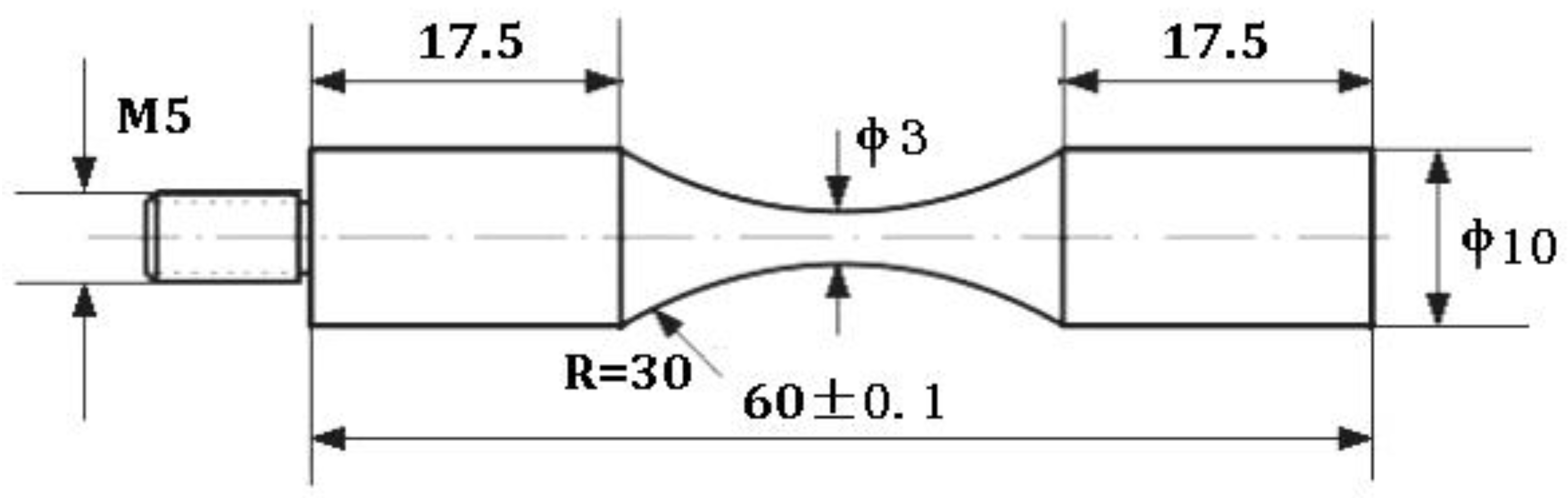
The test specimen in this investigation was a Ti6Al4V shaft with the following chemical composition (mass %): C—0.007~0.01, Fe—0.017~0.02, N—0.007~0.009, O—0.190~0.195, H—0.001, Al—6.408~6.411, V—4.403~4.406, and balance Ti. The dimensions of the fatigue sample are illustrated in Figure 1. All of the specimens are stress-relief annealed (SRA) at 650 °C for 4 h after machining, and then half of them are treated with solid solution-aging (SSA, 980 °C/1 h + water quenching and 580 °C/8 h + furnace cooling). They are polished using sandpaper from grade 120 to grade 1500 before UNSM.
UNSM is an international patent owned by Sun-Moon University. It is expounded by Suh et al. [21]. The ultrasonic strikes cause severe plastic deformation to the surface and induce nanocrystals. The static load applied on the specimen was 25 N, and the vibration amplitude was 30 μm. The sum of the static load and the sinusoidal function of the dynamic load is the total load acting on the specimen. In this paper, it is stricken for 36,000 times per square millimeter.
Observation of the cross-sectional was performed with an optical microscope (CMM-20E, Changfang, Chengdu, China) and a scanning electron microscopy (SEM, S-3400N, Hitachi, Nantong, China). The samples were finally etched in Kroll’s reagent (HNO3:HF:H2O = 3:6:90, Vol %) at room temperature.
The microhardness was measured by a Vickers hardness tester (MMT-7, Matsuzawa, Tokushima, Japan) with a load of 50 g and a duration of 20 s. The surface topography after UNSM was scanned using an Asylum Research MFP-3D atomic force microscope (AFM, FSM-Precision, Chongqing, China). X-ray diffraction (XRD) was used to measure the residual stress using Rigaku X’pert pro MPD (Chengdu, China). The Cu Kα radiation (λ = 1.54184 Å) was chosen, and the diffraction lattice plane (213) was examined within a range 2θ of 136~146°. The XRD patterns were investigated within a range 2θ of 30~80° by the same machine.
To investigate the influences of the ultrasonic surface impacts on the fatigue fracture behavior of TC4, symmetric tension-compression fatigue tests (R = −1) on the four groups of samples (SRA, SSA, SRA-UNSM, SSA-UNSM, Table 1) were conducted using a piezoelectric ultrasonic fatigue test machine (USF-2000, Shimadzu, Chengdu, China). The frequency of fatigue testing was 20 kHz. The fracture surfaces were examined by SEM (JEOL JSM-6510LV, Chengdu, China).
3. Results and Discussion
3.1. Observation of the Severe Plastic Deformation Layer
By means of transmission electron microscope, the variations of grain size and the microstructures of the SPD layer have been reported widely [1,2]. There is consensus that nanocrystals can be obtained in these SPD layers. It is well known that the mechanical properties of TC4 depend on the percentage, size, and shape of the α-phase. The solid solution-aging treatment produces bimodal microstructures consisting of equiaxed α grains and a lamellar structure for TC4, and it releases the continuous α-phase [20]. It can be concluded that the strength of SSA is increased, while its plasticity is decreased (Table 2). The hexagonal close packed (hcp) α-phase has a high SFE—more than 300 mJ/m2—and the body-centered cubic (bcc) β-phase theoretically has 12 slip directions. The mechanism of grain refining in TC4 is mainly dislocation motion. Besides, due to the low symmetry of the hexagonal, twinning is also found in α-titanium [22]. The microstructures are shown in Figure 2. It can be concluded that nearly the same depth (40 μm) of SPD layers were achieved on both SRA (equiaxed structure) and SSA (duplex structure) specimens.
The XRD patterns of these four groups of TC4 specimens are compared in Figure 3. It can be seen that the β-phase transition actually occurs with the solid solution aging heat treatment. By means of UNSM, the intensity of characteristic peak α (101) is strengthened. The ultrasonic surface impact does not induce the phase change, as it is observed in stainless steel [23]. Taking the full width at half maximum (FWHM), the average grain size of the SPD layer can be calculated by the equation given by Scherrer and Wilson [24]. It is less than 100 nm.
3.2. Hardness and Residual Stress Distrubutions
The micro-Vickers hardness and surface residual stress along the depth were measured, as depicted in Figure 4. The microhardness of the SRA TC4 specimen is about 310 HV, and it is about 340 HV to SSA. The values of SRA-UNSM and SSA-UNSM are 380 HV (approximately 22% improved), and 395 HV (about 16% improved), respectively. The microhardness of the specimen with UNSM rapidly decreases from the surface to the depth of 120 μm, and then decreases more gradually. The Hall–Petch theory illustrates that the hardness and the yield stress relate to the grain size [25]. This is also discussed in the other reports [26]. When the dislocation multiplication rate is balanced, the increase in strain will not reduce the subgrain size any further. For example, Suh et al. reported that the maximum surface hardness wasn’t improved even the parameters of UNSM are increased higher [27].
The surface residual stress of SRA is −19 MPa, while it is 30 MPa after solid solution-aging. It is obvious that UNSM induces compressive residual stress at the surface of TC4. The values of the compressive residual stress are 520 MPa to SRA-UNSM, and 544 MPa to SSA-UNSM. Compressive residual stress is the most important factor for increasing the fatigue resistance. The high compressive residual stress remains until a depth of 80 μm, and then it rapidly decrease to a depth of 200 μm. It affects the position and the shape of inner crack initiation, which shall be discussed in the ensuing paragraphs.
3.3. Surface Topography
Table 3 lists the surface roughness of TC4 before and after UNSM. Comparing with the Ra of the turned specimen (2.16 μm), the increase of roughness due to UNSM is negligible. Surfaces shall maintain good surface roughness after UNSM.
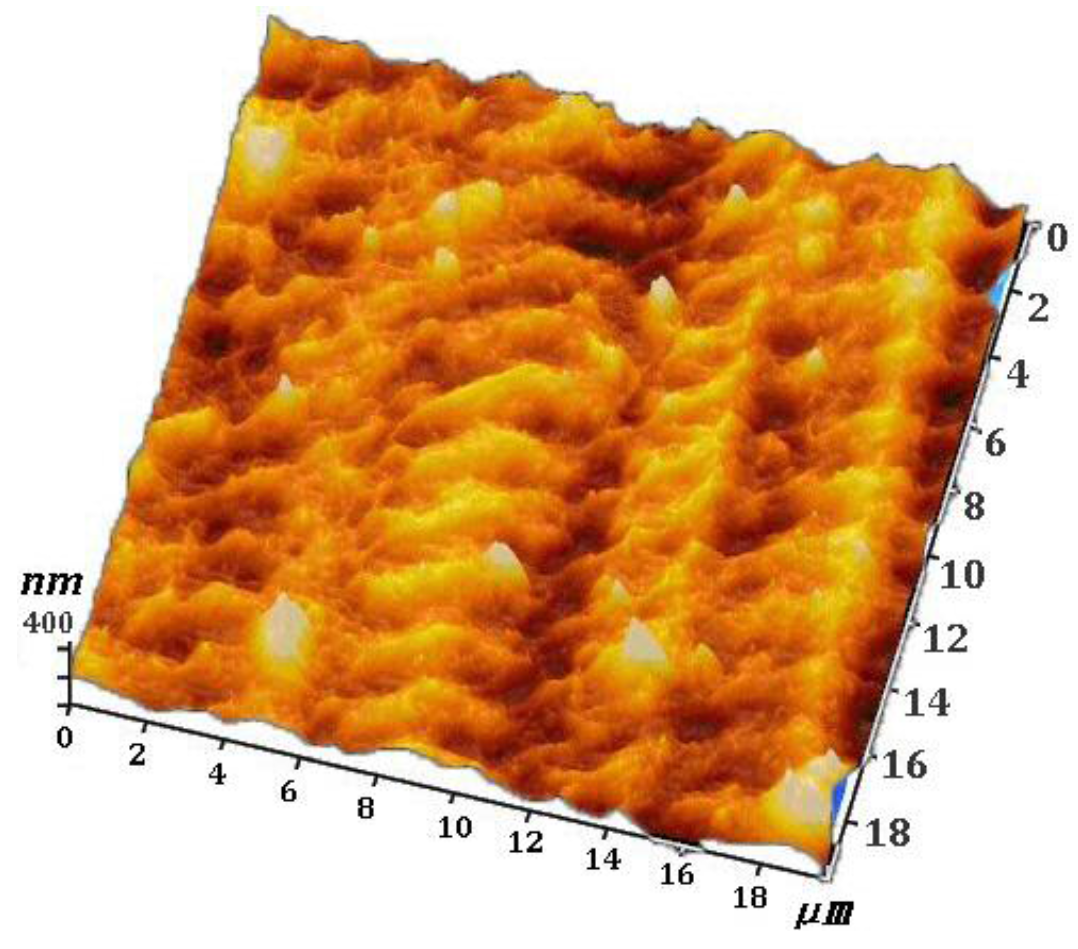
The surface feature of TC4 is shown in Figure 5. From the three-dimensional (3-D) AFM image, it is concluded that the grain deformation of TC4 shapes a regular surface with homogeneous microvoids. These microvoids improve the superficial area, and they are beneficial to cell adhension. The maximum altitude difference is controlled to several hundreds of nanometers. Comparing with other surface treatment technologies, the surface of the UNSMed specimen is controllable. The surface morphology plays an important role in the wear and corrosion resistance [28,29]. Thus, it is necessary to search for an optimal arameter combination.
3.4. Fatigue Fracture Characteristics
The fatigue characteristics of TC4 subjected to UNSM are shown in Figure 6. Specimens that did not encounter failure are shown as run-outs. Fish-eye-type cracks are marked with short vertical bars. Inner cracks are observed on the specimens with UNSM, while the fatigue lives are more than 106 cycles. In contrast, all of the un-UNSMed specimens show the surface cracks, no matter the fatigue life. From the S–N curves, it is evident that UNSM improves the 108 cycles fatigue strength of TC4. The fatigue strength of SRA-UNSM is increased by 7.0%, while that of SSA-UNSM is increased by 11.7%.
Figure 7 shows the SEM micrographs of the fatigue fracture surfaces. The crack initiation mechanism of axial symmetric tension-compression fatigue is different from that of rotating bending fatigue. All of the cracks initiate from the surface of S45C specimens after UNSM, which are subjected to rotating bending fatigue [30]. A nano-structured layer is achieved on the surface of the surface self-nanocrystallized (SSN) specimen. Underneath is a refined structured layer consisting of submicrometer-sized crystallites, or cells separated by either grain boundaries or subboundaries, up to about 100 μm [1]. Deformed coarse grains are in deeper layers, to a certain depth. Noticeably, the cores of inner cracks are at the zone with a depth of about 100~250 μm, where the compressed residual stress and hardness are far below that of the surface. Plasticity and tenacity are weaker in this zone, too. High light white areas appear in the crack core. Their shapes are long and narrow because of the ultrasonic impacts on the surface. EDX (Energy-Dispersive X-ray spectroscopy) results show that they are not typical inclusions, and these high light white areas are nonexistant in un-UNSMed specimens [31,32,33]. An interior crack core of TC4 without severe surface plastic deformation has a circular or elliptical rough area [20]. There are a few white bands from the crack core to the boundary between the crack initiation area and the crack propagation area, and some go across to the nearest edge. These high light white area and white bands are compress deformed α-phases, which are easier for the propagation of microcracks in the crack initiation area. Surface cracks are also investigated at high stress level because of the surface blemish.
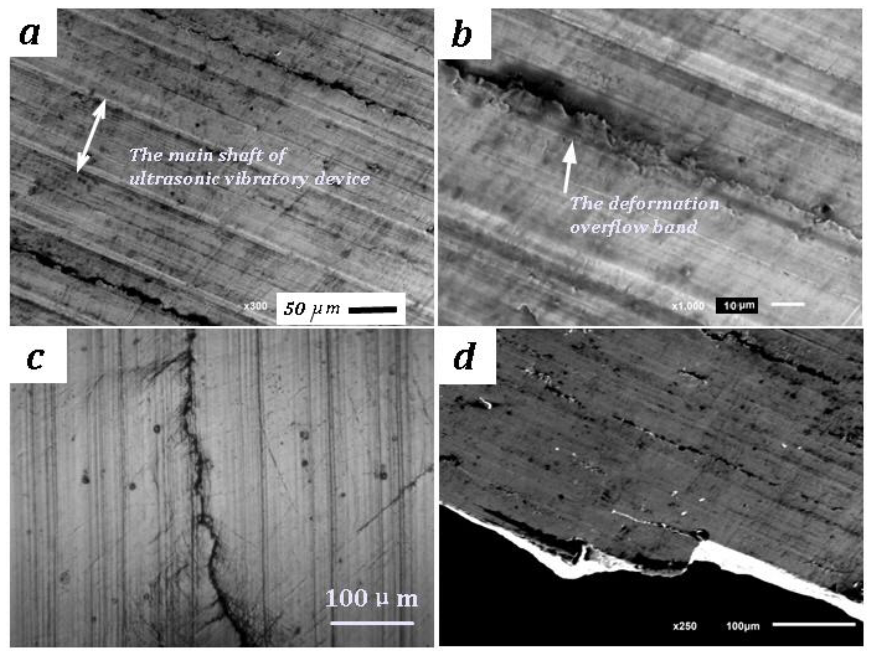
Figure 8 is the observation of the surface crack propogation. On the surface of UNSMed TC4 after axial symmetric tension-compression fatigue, there are some deformation overflow bands that are parallel to the process traces. The distance between the bands is about 260 μm. However, the deformation overflow bands cannot be distinguished in optical micrographs. They might be induced more clearly because of the crack slip during the fatigue test. The surface cracks preferentially extend along them, and microcracks easily split in the local zone. The steps of crack propagation are observed, because cracks change lanes to the process traces sometimes through the discontinuous longitudinal microcracks. They were also investigated by Suh [27]. This means that the energy field of crack evolution depends on both the deformed crystal slip and the surface remodeling.
The detailed observations of fracture surface are shown in Figure 9. The sliding lines of the slip of the α-phase can be seen on the white bands. Rapid surface slip is the mainly reason for crack propagation to TC4 alloy. In the crack extension area, the slip shows many quasi-cleavage planes. For the specimens without UNSM treatment, the dimples are shown as equal-axis ductile voids. However, they progressively grow smaller until annihilation to the edge at the fatigue rupture region after UNSM. The feature of dimples transforms to parabolic fossa and an oval toughening nest due to the dimensional change of grains. The micro-dimples near the edge are within the diameter of tens of nanometers distributed in the SPD layer. It is also deduced that nanocrystals are achieved by UNSM. The fatigue fracture of TC4 is transcrystalline plastic.
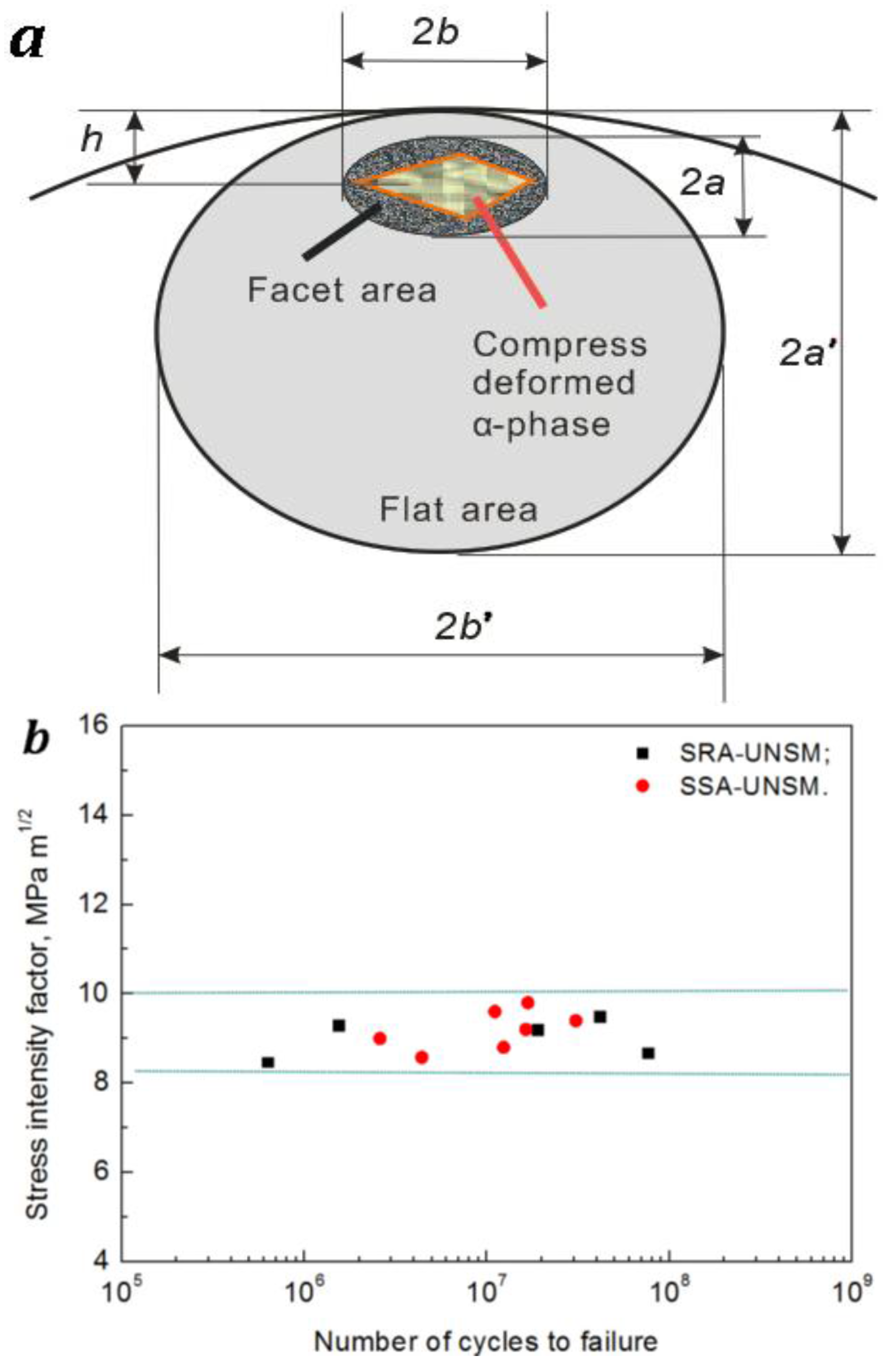
The fish eye-type fracture surface is divided into three areas: inclusion area, facet area, and flat area. A first area is the inclusion in the center of a fish eye, which changes to a compress deformed α-phase to TC4 with UNSM instead. The second is the facet area with a rough surface, as shown in Figure 7c. The third area is the area with flat surface located around this facet area. The flat area is seen as a dark grey ellipse. The stress intensity factor, ΔK, which is relevant to these three different regions described above, can be calculated by Equations (1) and (2) [34,35,36],
where σa is the nominal stress amplitude at the surface, σat is the stress amplitude at the compress deformed α-phase, d is the diameter of the specimen, h is the depth of the compress deformed α-phase, and area is the area of each part. The results are plotted in Figure 10. It is seen that the stress intensity factor calculated from the facet area ΔKfacet was in the range of 8.3–10.0 MPa·m1/2. The plastic zone size rP at the crack tip under plain strain conditions can be calculated by Equation (3) for a model-I crack [36],
where μ is Poisson’s ratio, and σy is the yield strength. Therefore, the plastic zone (rP is about 7.34 μm) shall be a little bigger than the average diameter of primary α grains (Figure 2a). This suggests that the slip of the deformed α phase induces the propagation of microcracks instead of intragranular platic expansion at the crack initiation zone.
4. Conclusions
The mechanical properties and fatigue fracture characteristics of TC4 subjected to UNSM were investigated, and the following results were obtained:
- UNSM technique improves the microhardness and the surface compressive residual stress of TC4. The ultrasonic surface impact helps to achieve a regular surface, almost without changing the surface roughness.
- The fatigue strengths of TC4 subjected with two different heat treatments are improved by 7% (to stress-relief annealing) and 11.7% (to solid solution-aging), respectively.
- After UNSM, fatigue cracks mainly initiate from the surface of the specimen before the fatigue life of 106 cycles, while they appear at the internal compress deformed α-phase at the zone between the SPD layer and the core after the fatigue life of 106 cycles. The shapes of crack cores are long and narrow because of the ultrasonic impacts on the surface.
- The dimples change from equal-axis ductile voids to be parabolic fossae and oval toughening nests due to the dimensional change of the grains.
- The stress intensity factor calculated from the facet area ΔKfacet was in the range of 8.3–10.0 MPa·m1/2. The slip of the deformed α phase induces the propogation of microcracks.
- The energy field of crack evolution depends on both the deformed crystal slip and the surface remodeling.
Acknowledgments
The authors thank DesignMecha Co., Ltd. (Asan, Korea) for the assistance of UNSM. The financial support extended by National Natural Science Foundation of China (11327801), Natural Science Foundation of Jiangsu Province (BK20160416) and Natural Science Foundation of Sichuan Province (16ZB0034) are gratefully acknowledged.
Author Contributions
Q.Y. Wang conceived and designed the experiments; X.J. Cao performed the experiments; X.L. Xu analyzed the mechanical tests; L.P. Xu analyzed the micro pictures; X.J. Cao wrote the paper.
Conflicts of Interest
The authors declare no conflict of interest.
References
- Lu, K.; Lu, J. Nanostructured surface layer on metallic materials induced by surface mechanical attrition treatment. Mater. Sci. Eng. A 2004, 375–377, 38–45. [Google Scholar] [CrossRef]
- Maawad, E.; Sano, Y.; Wagner, L.; Brokmeier, H.-G.; Genzel, C. Investigation of laser shock peening effects on residual stress state and fatigue performance of titanium alloys. Mater. Sci. Eng. A 2012, 536, 82–91. [Google Scholar] [CrossRef]
- Cain, V.; Thijs, L.; Van Humbeeck, J.; Van Hooreweder, B.; Knutsen, R. Crack propagation and fracture toughness of Ti6Al4V alloy produced by selective laser melting. Addit. Manuf. 2015, 5, 68–76. [Google Scholar] [CrossRef]
- Yu, S.; Liu, D.; Zhang, X.; Du, D. Effects of combined plasma chromizing and shot peening on the fatugue properties of a Ti6Al4V alloy. Appl. Surf. Sci. 2015, 353, 995–1002. [Google Scholar] [CrossRef]
- Tang, C.; Liu, D.; Tang, B.; Zhang, X.; Qin, L.; Liu, C. Influence of plasma molybdenizing and shot-peening on fretting damage behavior of titanium alloy. Appl. Surf. Sci. 2016, 390, 946–958. [Google Scholar] [CrossRef]
- Simonelli, M.; Tse, Y.Y.; Tuck, C. Effect of the build orientation on the mechanical properties and fracture modes of SLM Ti-6Al-4V. Mater. Sci. Eng. A 2014, 616, 1–11. [Google Scholar] [CrossRef]
- Batory, D.; Szymanski, W.; Panjan, M.; Zabeida, O.; Klemberg-Sapieha, J.E. Plsma nitriding of Ti6Al4V alloy for improved water erosion resistance. Wear 2017, 374–375, 120–127. [Google Scholar] [CrossRef]
- Liu, W.Y.; Lin, Y.H.; Chen, Y.H.; Shi, T.; Ambrish, S. Effect of different heatments on microstructure and mechanical peoperties of Ti6Al4V titanium alloy. Rare Met. Mater. Eng. 2017, 46, 634–639. [Google Scholar]
- Chen, S.X.; Usta, A.D.; Eriten, M. Microstructure and wear resistance of Ti6Al4V surfaces processed by pulsed laser. Surf. Coat. Technol. 2017, 315, 220–231. [Google Scholar] [CrossRef]
- Lu, K.; Lu, J. Surface nanocrystallization (SNC) of metallic materials-presentation of the concept behind a new approach. J. Mater. Sci. Technol. 1999, 15, 193–197. [Google Scholar]
- Bloyce, A.; Morton, P.; Bell, T. ASM Handbook; ASM International: Materials Park, OH, USA, 1994; Volume 5, p. 835. [Google Scholar]
- Liu, K.K.; Hill, M.R. The effects of laser peening and shot peening on fretting fatigue in Ti−6Al−4V coupons. Tribol. Int. 2009, 42, 1250–1262. [Google Scholar] [CrossRef]
- Chen, G.; Jiao, Y.; Tian, T.; Zhang, X.; Li, Z.; Zhou, W. Structure, microhardness and damping characteristics of Al matrix composite reinforced with AlCuFe or Ti using ultrasonic impact peening. Surf. Coat. Technol. 2010, 204, 1590–1598. [Google Scholar]
- Chen, G.Q.; Jiao, Y.; Tian, T.Y.; Zhang, X.; Li, Z.; Zhou, W. Effect of wet shot peening on Ti−6Al−4V alloy treated by ceramic beads. Trans. Nonferrous Met. Soc. China 2014, 24, 690–696. [Google Scholar] [CrossRef]
- Srinivasan, S.; Garcia, D.B.; Gean, M.C.; Murthy, H.; Farris, T.N. Fretting fatigue of laser shock peened Ti–6Al–4V. Tribol. Int. 2009, 42, 1324–1329. [Google Scholar] [CrossRef]
- Tsuji, N.; Tanaka, S.; Takasugi, T. Effects of combined plasma-carburizing and shot-peening on fatigue and wear properties of Ti–6Al–4V alloy. Surf. Coat. Technol. 2009, 203, 1400–1405. [Google Scholar] [CrossRef]
- Stanzl-Tschegg, S. Fatigue crack growth and thresholds at ultrasonic frequencies. Int. J. Fatigue 2006, 28, 1456–1464. [Google Scholar] [CrossRef]
- Morrissey, R.; Nicholas, T. Staircase testing of a titanium alloy in the gigacycle regime. Int. J. Fatigue 2006, 28, 1577–1582. [Google Scholar] [CrossRef]
- Sun, W.; Tan, A.W.Y.; Khun, N.W.; Marinescu, I.; Liu, E. Effect of substrate surface condition on fatigue behavior of cold sprayed Ti6Al4V coatings. Surf. Coat. Technol. 2017, 320, 452–457. [Google Scholar] [CrossRef]
- Liu, X.L.; Sun, C.Q.; Hong, Y.S. Effects of stress ratio on high-cycle and very-high-cycle fatigue behavior of a Ti-6Al-4V alloy. Mater. Sci. Eng. A 2015, 622, 228–235. [Google Scholar] [CrossRef]
- Suh, M.S.; Suh, C.M.; Pyun, Y.S. Very high cycle fatigue characteristic of a chrome-molybdenum steel treated by ultrasonic nanocrystal surface modification technique. Fatigue Fract. Eng. Mater. Struct. 2013, 36, 769–778. [Google Scholar] [CrossRef]
- Zhu, K.Y.; Vassel, A.; Brisset, F.; Lu, K.; Lu, J. Nanostructure formation mechanism of α-titanium using SMAT. Acta Mater. 2004, 52, 4101–4110. [Google Scholar] [CrossRef]
- Yasuoka, M.; Wang, P.; Zhang, K.; Qiu, Z.; Kusaka, K.; Pyoun, Y.-S.; Murakami, R. Improvement of the fatigue strength of SUS304 austenite stainless steel using ultrasonic nanocrystal surface modification. Surf. Coat. Technol. 2013, 218, 93–98. [Google Scholar] [CrossRef]
- Klug, H.P.; Alexandrov, L.E. X-ray Diffraction Procedures for Polycrystalline and Amorphous Materials, 2nd ed.; Wiley: New York, NY, USA, 1974; p. 662. [Google Scholar]
- Hall, E.O. The Deformation and Ageing of Mild Steel: III Discussion of Results. Proc. Phys. Soc. 1951, 64, 747–753. [Google Scholar] [CrossRef]
- Wu, B.; Wang, P.P.; Pyoun, Y.S.; Zhang, J.; Murakami, R. Study on the fatigue properties of plasma nitriding S45C with a pre-ultrasonic nanocrystal surface modification process. Surf. Coat. Technol. 2013, 216, 191–198. [Google Scholar] [CrossRef]
- Suh, M.-S.; Pyoun, Y.-S.; Suh, C.-M. Variation of fatigue properties in nanoskinned Ti-6Al-4V—Rotating bending and axial loading tension-compression cycle. Trans. Korean Soc. Mech. Eng. A 2012, 36, 443–449. [Google Scholar] [CrossRef]
- Sola, R.; Poli, G.; Veronesi, P.; Giovanardi, R. Effects of surface morphology on the wear and corrosion resistance of post-treated Nitrided and nitrocarburized 42CrMo4 steel. Metall. Mater. Trans. A 2014, 45, 2827–2833. [Google Scholar] [CrossRef]
- Sola, R.; Poli, G.; Veronesi, P.; Giovanardi, R.; Mamei, S.; Zanotti, A. Effect of surface finishing and post-oxidation atmosphere on the properties of 41CrAlMo7 nitrided steel. Metall. Ital. 2012, 104, 35–40. [Google Scholar]
- Cao, X.J.; Murakami, R.; Pyoun, Y.S. Fatigue properties of a S45C steel subjected to ultrasonic nanocrystal surface modification. Appl. Surf. Sci. 2010, 256, 6297–6303. [Google Scholar] [CrossRef]
- Cao, X.J.; Xu, X.L.; Wang, C.; Pyoun, Y.; Wang, Q. Effect of ultrasonic surface impact on the fatigue behavior of Ti-6Al-4V subject to simulated body fluid. Metals 2017, 7, 440. [Google Scholar] [CrossRef]
- Murakami, Y. Metal fatigue: Influence of micro defect and inclusion; Yokenndo: Tokyo, Japan, 1993. (In Japanese) [Google Scholar]
- Ochi, Y.; Matsumura, T.; Masaki, K.; Yoshida, S. High-cycle rotating bending fatigue property in very long-life regime of high-strength steels. Fatigue Fract. Eng. Mater. Struct. 2002, 25, 823–830. [Google Scholar] [CrossRef]
- Sakai, T.; Sato, Y.; Oguma, N. Characteristic S-N properties of high-carbon-chormium-bearing steel under axial loading in long-life fatigue. Fatigue Fract. Eng. Mater. Struct. 2002, 25, 765–773. [Google Scholar] [CrossRef]
- Zhu, S.-P.; Lei, Q.; Huang, H.-Z.; Yang, Y.-J.; Peng, W. Mean stress effect correction in strain energy-based fatigue life prediction of metals. Int. J. Damage Mech. 2017, 26, 1219–1241. [Google Scholar] [CrossRef]
- Hertzberg, R.W.; Vinci, R.P.; Hertzberg, J.L. Deformation and Fracture Mechanics of Engineering Materials, 5th ed.; Wiley: Hoboken, HJ, USA, 2012. [Google Scholar]
Figure 1.
Dimension of the fatigue sample (all dimensions are in mm).

Figure 2.
Microstructure and dissimilation surface layer of TC4: (a) SRA; (b) SSA; (c) SRA-UNSM; (d) SSA-UNSM.
Figure 2.
Microstructure and dissimilation surface layer of TC4: (a) SRA; (b) SSA; (c) SRA-UNSM; (d) SSA-UNSM.
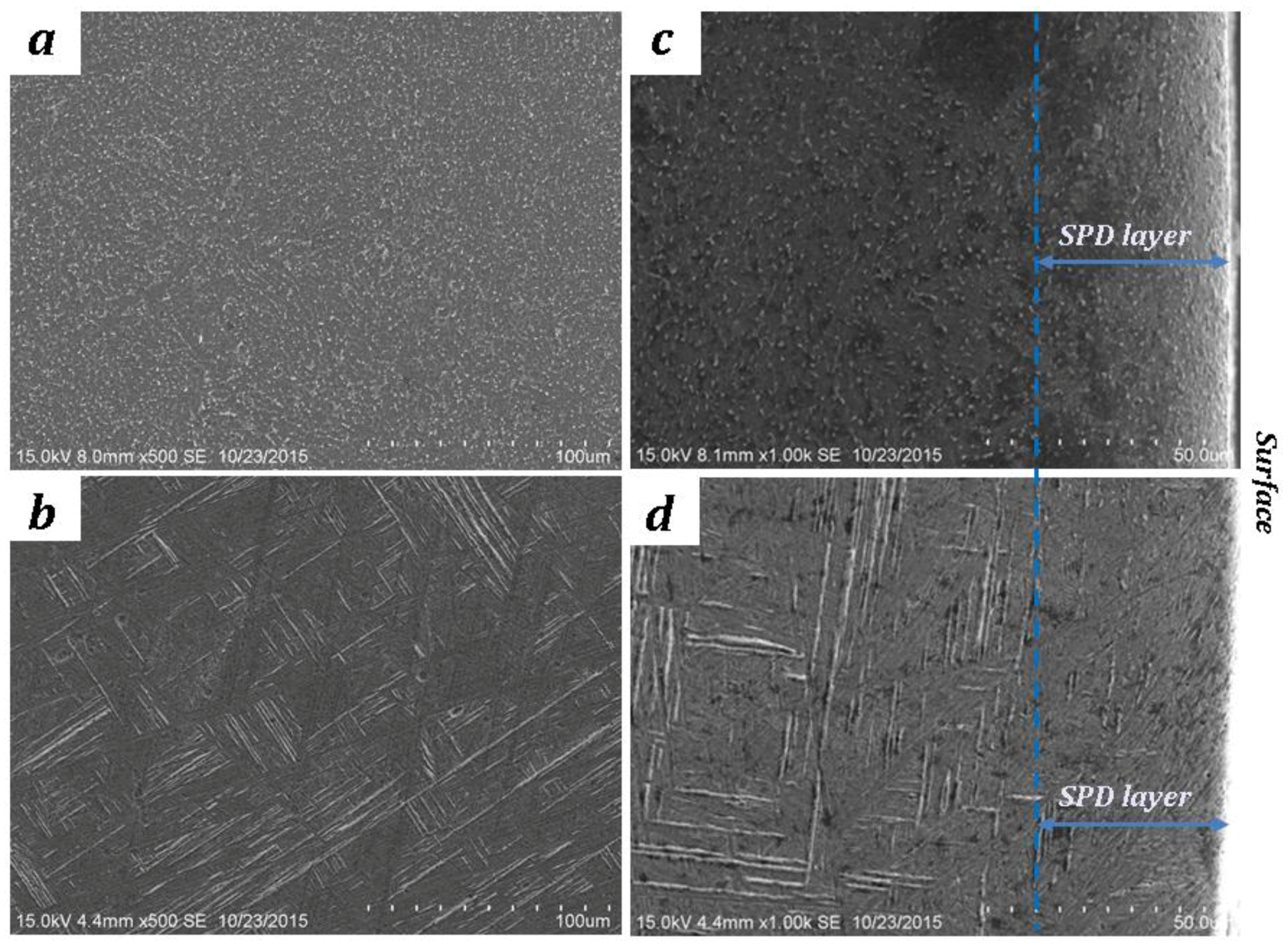
Figure 3.
XRD patterns of Ti6Al4V.
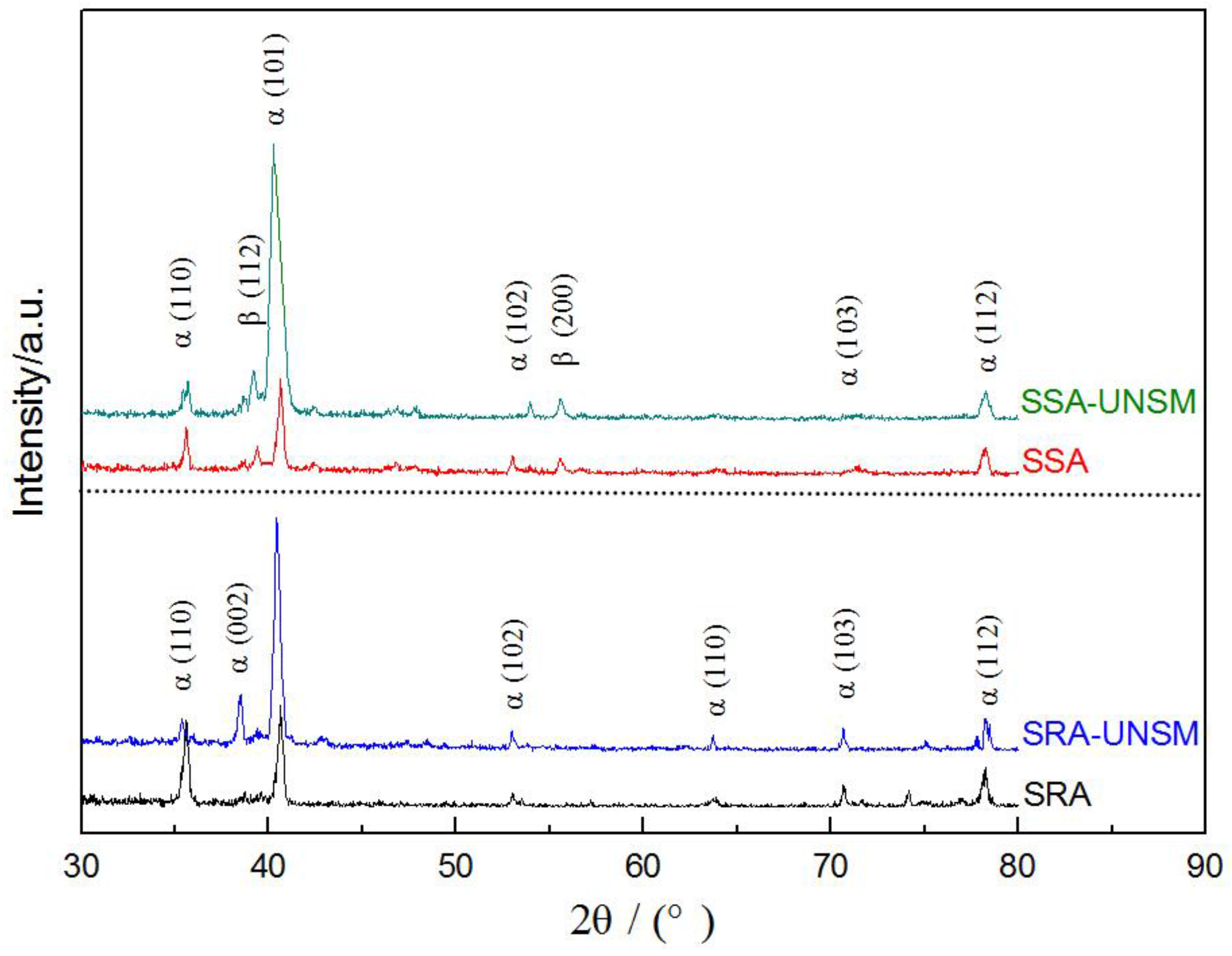
Figure 4.
Variation of hardness and compressive residual stress of TC4 after UNSM: (a) SRA; (b) SSA.
Figure 4.
Variation of hardness and compressive residual stress of TC4 after UNSM: (a) SRA; (b) SSA.
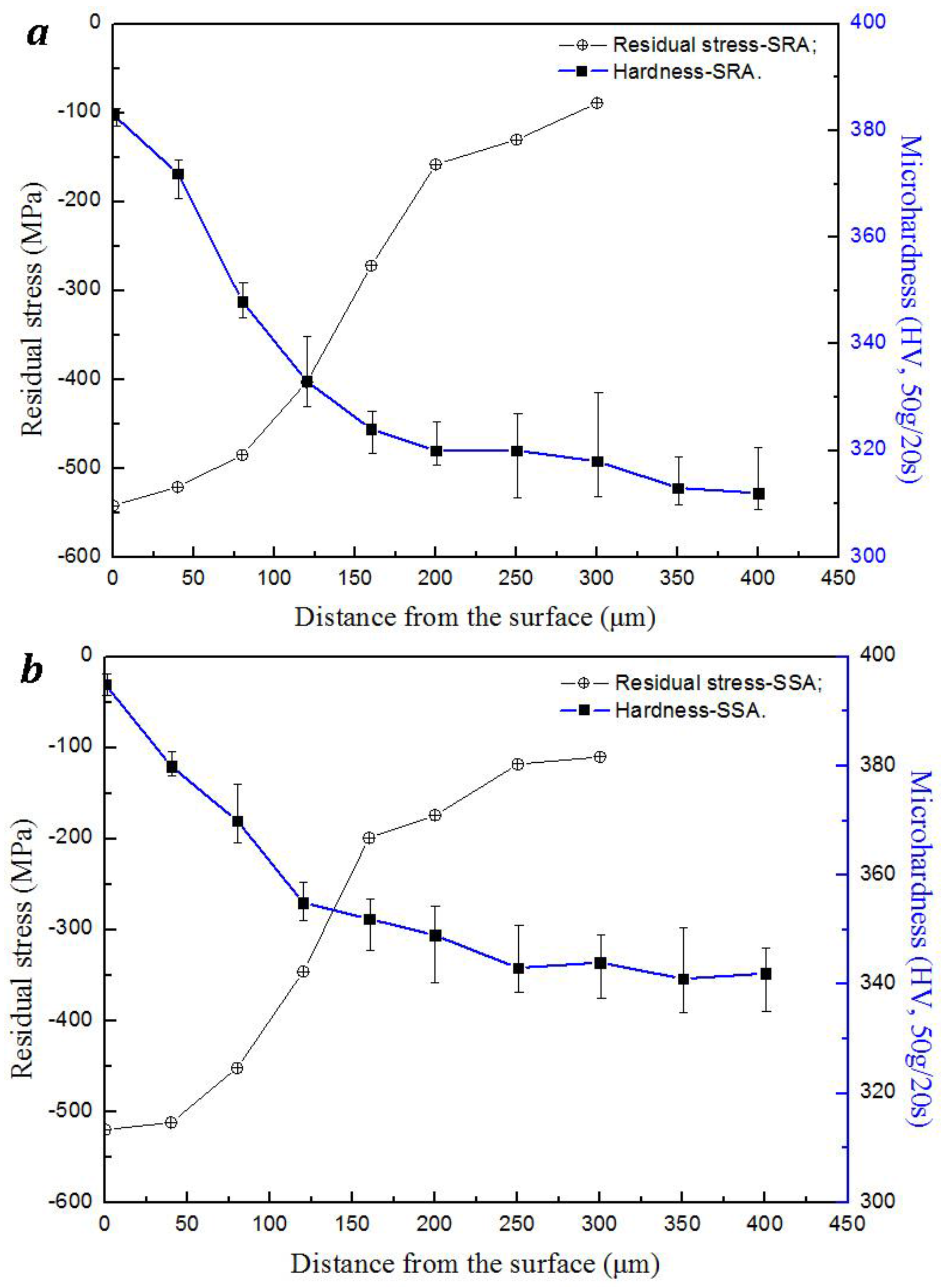
Figure 5.
Three-dimensional (3-D) microscope image of UNSMed Surface feature by atomic force microscope (AFM).
Figure 5.
Three-dimensional (3-D) microscope image of UNSMed Surface feature by atomic force microscope (AFM).

Figure 6.
S–N curves of TC4 before and after UNSM.
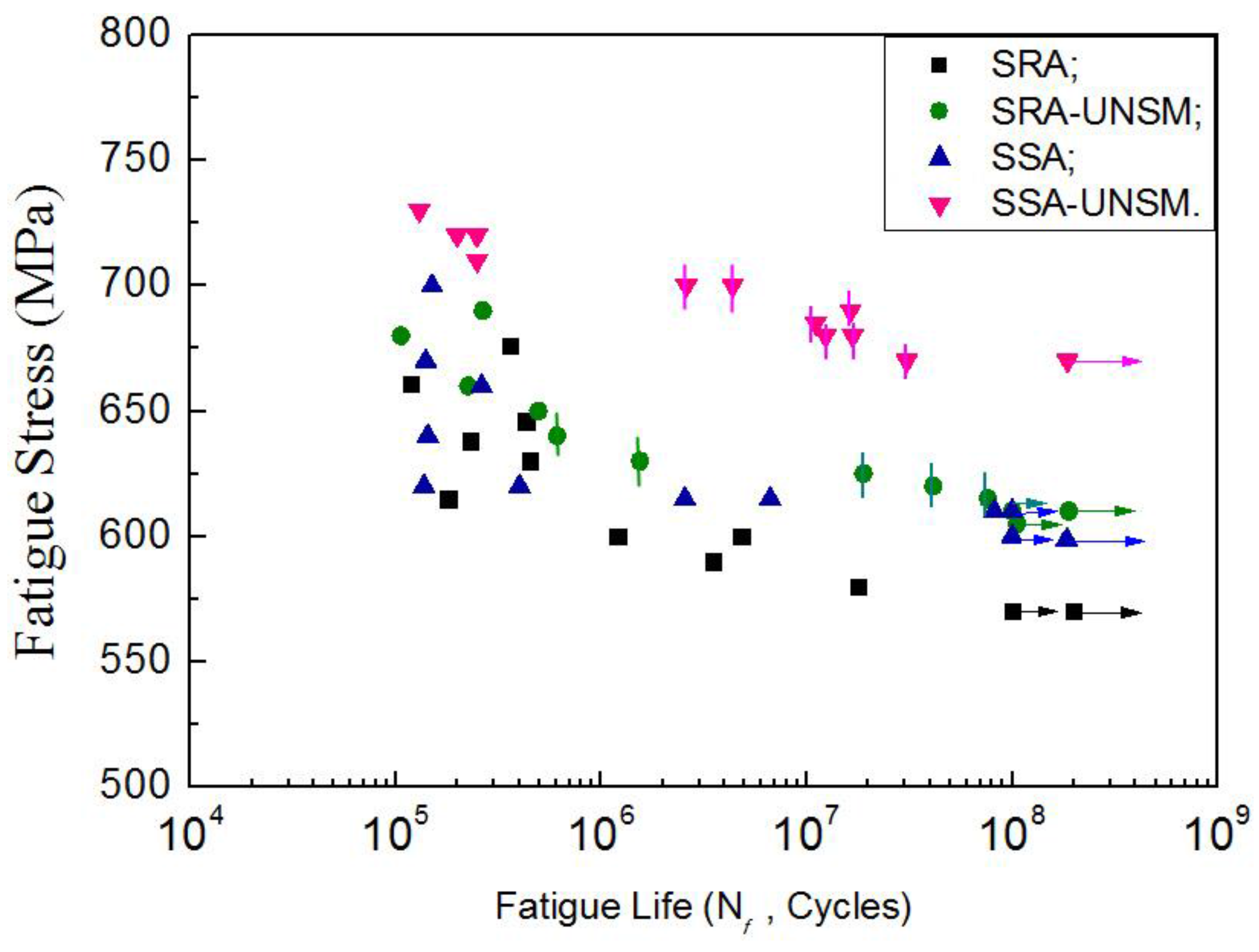
Figure 7.
Crack initiations of TC4: (a) (SRA-UNSM, 630 MPa, 2.13 × 10⁷ cycles); (b) SA-UNSM, 680 MPa, 3.07 × 10⁷ cycles; (c) Facets in the interior crack; (d) Surface crack initiation, (SRA-UNSM, 650 MPa, 4.94 × 10⁵ cycles).
Figure 7.
Crack initiations of TC4: (a) (SRA-UNSM, 630 MPa, 2.13 × 10⁷ cycles); (b) SA-UNSM, 680 MPa, 3.07 × 10⁷ cycles; (c) Facets in the interior crack; (d) Surface crack initiation, (SRA-UNSM, 650 MPa, 4.94 × 10⁵ cycles).
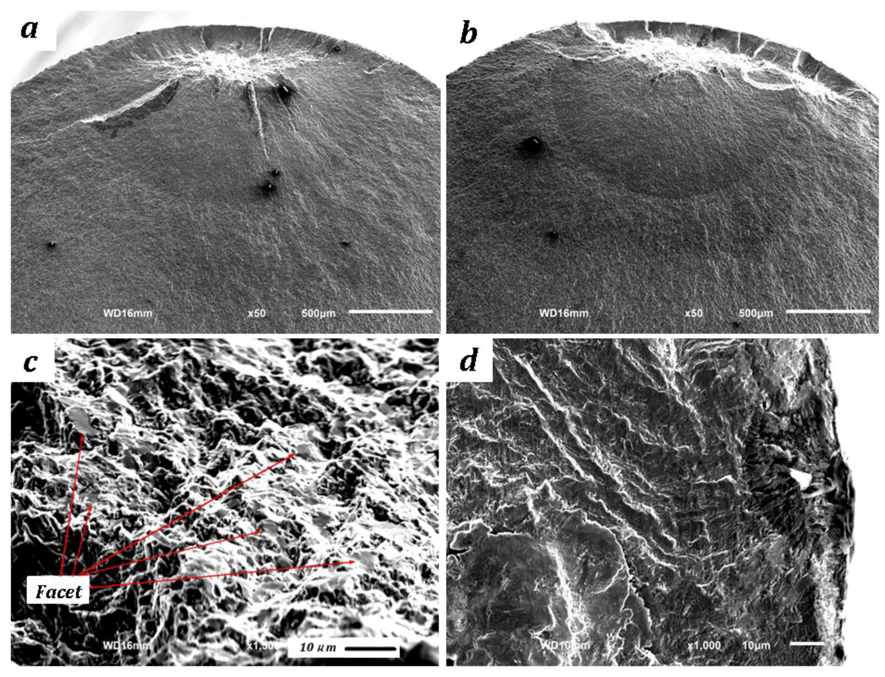
Figure 8.
Observation of the surface crack: (a) Specimen surface after fatigue test; (b) Deformation overflow band; (c) Surface crack propagation; (d) Step of surface crack.
Figure 8.
Observation of the surface crack: (a) Specimen surface after fatigue test; (b) Deformation overflow band; (c) Surface crack propagation; (d) Step of surface crack.

Figure 9.
Observation of the fracture surface: (a) Sliding lines on a white band; (b) Quasi-cleavage plane; (c) Equal-axis ductile dimples of un-UNSMed specimen; (d) Parabolic fossae and oval toughening nests of SSA-UNSM beneath the surface.
Figure 9.
Observation of the fracture surface: (a) Sliding lines on a white band; (b) Quasi-cleavage plane; (c) Equal-axis ductile dimples of un-UNSMed specimen; (d) Parabolic fossae and oval toughening nests of SSA-UNSM beneath the surface.
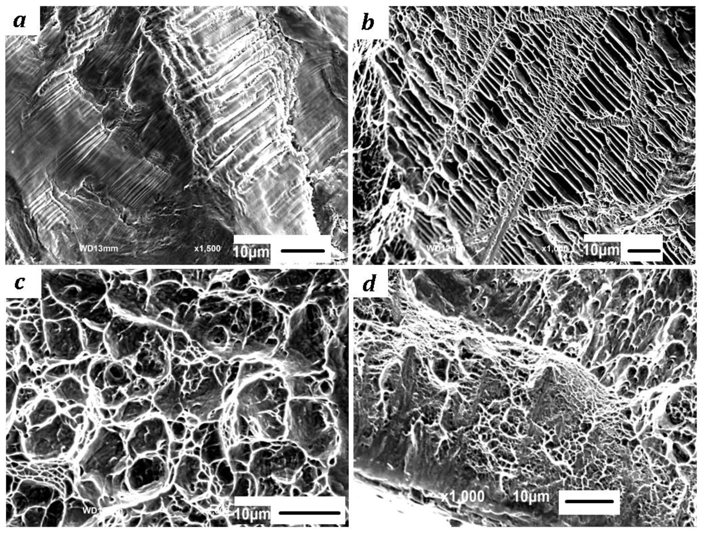
Figure 10.
Stress intensity factor of TC4 with UNSM: (a) Schematic illustration of a fish-eye type fracture after UNSM; (b) Relationship between fatigue life and stress intensity factor.
Figure 10.
Stress intensity factor of TC4 with UNSM: (a) Schematic illustration of a fish-eye type fracture after UNSM; (b) Relationship between fatigue life and stress intensity factor.

Table 1.
Groups of specimen. SRA: stress-relief annealed; SSA: solid solution-aging; UNSM: ultrasonic nanocrystal surface modification.
Table 1.
Groups of specimen. SRA: stress-relief annealed; SSA: solid solution-aging; UNSM: ultrasonic nanocrystal surface modification.
| Groups | SRA | SRA-UNSM | SSA | SSA-UNSM | |
|---|---|---|---|---|---|
| Treatments | |||||
| Stress-relief annealing | 〇 | 〇 | |||
| Solid solution and aging | 〇 | 〇 | |||
| With UNSM | 〇 | 〇 | |||
Table 2.
The mechanical properties of Ti6Al4V (TC4).
| Heat Treatment | σ0.2/MPa | σb/MPa | Elongation/% | Reduction of Area/% |
|---|---|---|---|---|
| Stress-relief annealing | 850 | 925 | 16 | 26 |
| Solid solution & aging | 1180 | 1230 | 14 | 10 |
Table 3.
Surface roughness of TC4 after UNSM.
| Group | SRA | SRA-NSM | SSA | SSA-UNSM |
|---|---|---|---|---|
| Roughness (Ra) | 0.35 μm | 0.5 μm | 0.39 μm | 0.58 μm |
© 2018 by the author. Licensee MDPI, Basel, Switzerland. This article is an open access article distributed under the terms and conditions of the Creative Commons Attribution (CC BY) license (http://creativecommons.org/licenses/by/4.0/).
Share and Cite
MDPI and ACS Style
Cao, X.; Xu, L.; Xu, X.; Wang, Q. Fatigue Fracture Characteristics of Ti6Al4V Subjected to Ultrasonic Nanocrystal Surface Modification. Metals 2018, 8, 77. https://doi.org/10.3390/met8010077
AMA Style
Cao X, Xu L, Xu X, Wang Q. Fatigue Fracture Characteristics of Ti6Al4V Subjected to Ultrasonic Nanocrystal Surface Modification. Metals. 2018; 8(1):77. https://doi.org/10.3390/met8010077
Chicago/Turabian StyleCao, Xiaojian, Luopeng Xu, Xiaoli Xu, and Qingyuan Wang. 2018. "Fatigue Fracture Characteristics of Ti6Al4V Subjected to Ultrasonic Nanocrystal Surface Modification" Metals 8, no. 1: 77. https://doi.org/10.3390/met8010077
Note that from the first issue of 2016, this journal uses article numbers instead of page numbers. See further details here.