High-Temperature Creep-Fatigue Behavior of Alloy 617


1
Department of Mechanical Design Engineering, Pukyong National University, Busan 48547, Korea
2
Department of Steel Industry, Pohang University, Pohang 37555, Korea
*
Author to whom correspondence should be addressed.
Metals 2018, 8(2), 103; https://doi.org/10.3390/met8020103
Submission received: 27 November 2017
/
Revised: 12 January 2018
/
Accepted: 25 January 2018
/
Published: 1 February 2018
(This article belongs to the Special Issue Fatigue of Intermetallics)
Abstract
:This paper presents the high-temperature creep-fatigue testing of a Ni-based superalloy of Alloy 617 base metal and weldments at 900 °C. Creep-fatigue tests were conducted with fully reversed axial strain control at a total strain range of 0.6%, 1.2%, and 1.5%, and peak tensile hold time of 60, 180, and 300 s. The effects of different constituents on the combined creep-fatigue endurance such as hold time, strain range, and stress relaxation behavior are discussed. Under all creep-fatigue tests, weldments’ creep-fatigue life was less than base metal. In comparison with the low-cycle fatigue condition, the introduction of hold time decreased the cycle number of both base metal and weldments. Creep-fatigue lifetime in the base metal was continually decreased by increasing the tension hold time, except for weldments under longer hold time (>180 s). In all creep-fatigue tests, intergranular brittle cracks near the crack tip and thick oxide scales at the surface were formed, which were linked to the mixed-mode creep and fatigue cracks. Creep-fatigue interaction in the damage-diagram (D-Diagram) (i.e., linear damage summation) was evaluated from the experimental results. The linear damage summation was found to be suitable for the current limited test conditions, and one can enclose all the data points within the proposed scatter band.
1. Introduction
The very-high-temperature reactor (VHTR) of Generation-IV type systems is being developed as a nuclear system with helium as the primary coolant, and is designed to produce an effective heat for hydrogen generation and electricity production [1,2]. The conceptual design reaches a maximum expected outlet temperature of about 950 °C to satisfy the efficient generation of hydrogen [3,4,5]. Popular materials for components of the system include Alloys 617, 230, and Hastelloy X, and are approved for non-nuclear construction under Section VIII of the American Society of Mechanical Engineers (ASME) boiler and pressure vessel (B&PV) design code, but nothing has been approved for the generation of nuclear plants [6,7]. The specifications of candidate materials with a combination of very-high-temperature operation and long duration of service requires structural materials with good thermal stability as well as high-temperature creep, fatigue (or combined creep-fatigue), and oxidation resistance. Based on these qualifications, the nickel-base Alloy 617 is the most promising candidate material for the intermediate heat exchanger (IHX) and hot gas duct (HGD) major components. It is necessary to conduct a laboratory simulation of the creep-fatigue phenomenon in Alloy 617 to supply the draft code case database. Although it will finally be used in the helium environment of the VHTR, the allowable design in the B&PV code refers to the time-dependent behavior in air [6]. Reports in studies in a helium environment showed that the growth rates of both oxide layer and penetration depth are considerably greater in a flowing helium environment than in air [3,6,7].
The current state of the problem is associated with historical development. Fatigue deformation is suspected to be a result of power transients and temperature gradients induced by thermal strain during operation, as well as during startups and shutdowns, and due to the temperature change of flowing coolant inducing cyclic damage; meanwhile, inherent stress relaxation during steady power operation induces creep deformation [8,9,10]. The creep-fatigue life depends on the environment, strain rate, strain range, duration of hold time, and microstructural heterogeneities such as the weldment component [7,8,11,12,13,14]. For mechanical structures, welds are critical considerations in the engineering design because they are the weakest links in the components and may have several inherent defects. Experience with nickel alloy weldments in structural applications suggests that most cases of high-temperature fatigue failures occurred in the weld metal part; see [1,2]. Literature reviews on Alloy 617 [3,4,5,6,7,8,9,10,15,16] have suggested that this alloy was sensitive to tensile hold time. It was reported that the allowable cycle number (fatigue life) was significantly reduced when the hold time at peak tensile strain (creep deformation) was introduced. These matters are the focus of this investigation. The current creep-fatigue data for any temperature range and conditions for both Alloy 617 base metal and weldments is limited. In order to understand the baseline high-temperature creep-fatigue behavior for Alloy 617, this study presents the creep-fatigue behavior of Alloy 617 base metal and weldments in air at 900 °C. Tests were performed with fully-reversed axial strain control at total strain range of 0.6%, 1.2%, and 1.5% and peak tensile hold time of 60, 180, and 300 s. The creep-fatigue results were analyzed with creep results from the literature to develop a creep-fatigue damage-diagram (D-Diagram); i.e., linear damage summation for Alloy 617. A linear damage summation rule is currently used in the ASME design codes for high-temperature creep-fatigue life assessment because of its applicability over a wide range of conditions and the plentiful availability of application data. The microscopic investigations were investigated by metallographic techniques on the selected specimens.
2. Materials and Methods
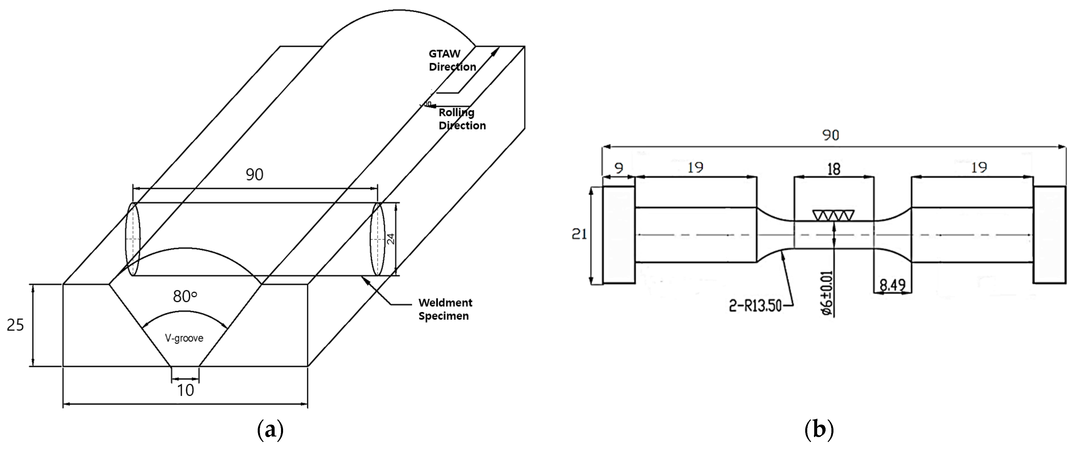
Alloy 617 is a solid-solution-strengthened commercial-grade Ni-Cr-Co-Mo-based superalloy with an exceptional combination of mechanical and physical resistance at high temperature [9]. It has a fine microstructure with a fully austenitic matrix. Major Ni and Cr contents make the alloy resistant to a variety of both reducing and oxidizing media. The Al and Cr components provide oxidation resistance at high temperatures, while the Co and Mo are responsible for the solid-solution strengthening [6,17]. The Alloy 617 used in this investigation was in a hot-rolled plate form with a thickness of 25 mm. Table 1 shows the chemical composition of the Alloy 617 and its filler wire (wt %), with representative images of the as-received microstructure shown in Figure 1. From the optically zoomed microstructure images shown in Figure 1, we could find that the initial microstructure of the base metal exhibited uniform equiaxed grain structures with a larger grain size of about 70–100 μm, and a fine smaller grain size of about 30–40 μm. The weld region comprised austenitic large columnar grains with dendritic structure due to solidification during the welding process. As such, the heat-affected zone (HAZ) of the weld showed carbide dissolution and a small amount of grain growth. Cylindrical specimens for weldments were machined from weld pad, as shown in Figure 2a. Figure 2b shows the cylindrical button-head specimen’s shape with dimensional information. It is worth mentioning that the size of the weldment (and location within the creep-fatigue specimen) varied somewhat, depending upon its location of dimensioning in the weld pad. The vertical length of the weld region was varied between 11 and 13 mm. Therefore, the gauge section of the weldment specimen was only covered with weld metal and HAZ materials.
A servo hydraulic testing machine (MTS 370, 100 kN) was used and equipped with a tube furnace for heating the specimens. The temperature was kept within ±2 °C of the nominal temperature during the test. The specimen was then held at a target temperature with zero load for 30 min to stabilize the temperature. Fully-reversed low-cycle fatigue and creep-fatigue testing were completed under 10−3/s constant strain rate at total strain ranges of 0.6%, 1.2%, and 1.5% at 900 °C in air. Low-cycle fatigue testing followed a triangular waveform, while creep-fatigue testing followed a trapezoidal waveform with a hold time imposed only at the maximum tensile strain of 60, 180, and 300 s, as shown in Figure 3. The failure criterion was defined as the cycle number which saw a 20% level drop off from the stress ratio (peak tensile over compressive stress ratio). Test termination was based on the drop in load to zero or specimen separation. These test procedures refer to the ASTM E2714 standard [18]. The tensile tests were done first as a reference. Figure 4 shows the tensile test results of Alloy 617 base metal and weldments, respectively. Alloy 617 base metal and weldment specimens showed a different characteristic of mechanical properties along their microstructural differences.
The post-fracture analysis of the selected specimens was investigated by using standard metallographic techniques. The creep-fatigue specimens were cut around crack initiation sites, and the cutting surfaces were polished after mounting, and they were sequentially etched in Kalling’s reagent composed of 100 mL hydrochloric acid, 100 mL ethyl alcohol, and 5 g cupric chloride.
3. Results
3.1. Creep-Fatigue Life
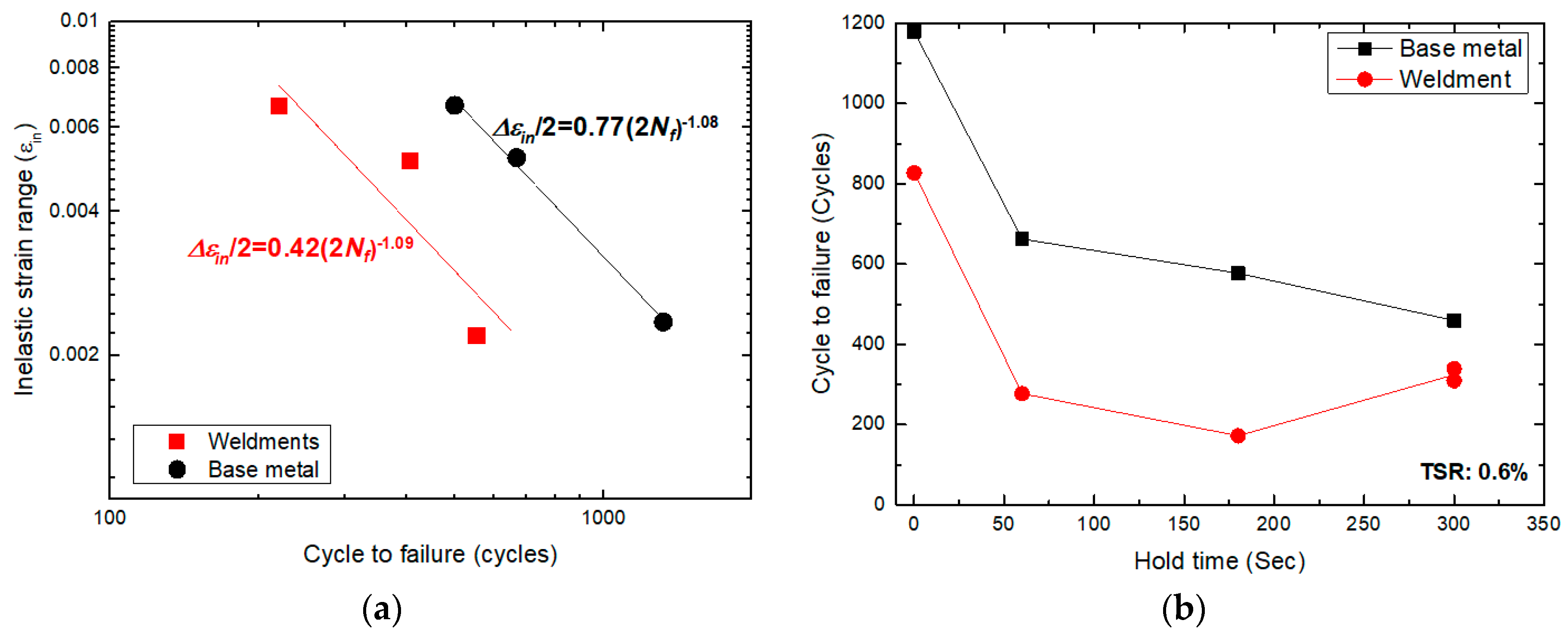
Continuous low-cycle fatigue tests including a variety of hold times were completed at 900 °C. Table 2 shows a summary of the results for a total strain range of 0.6%, 1.2%, and 1.5% and tensile holds of 60, 180, and 300 s at half-life—i.e., the inelastic strain range, stable stress, cycle number, and total test time to failure. Creep-fatigue life curves as a function of inelastic strain range and hold time for Alloy 617 base metal and weldments are shown in Figure 5. Figure 5a shows that the creep-fatigue life was decreased by increasing the total strain range. Figure 5b shows the fatigue life results regarding the three tensile hold times. In the current test, the cycle lifetimes for continuous low-cycle fatigue were reduced by roughly a factor of two for the lowest total strain range and hold time condition. Otherwise, a slight difference was found at higher total strain ranges. From the figures, the weldment creep-fatigue life was less than the base metal. The creep-fatigue life in the base metal was continually decreased by increasing the tension hold time. Otherwise, the effect of tensile hold time on weldment life did not show a reduction at a longer hold time (>180 s). This might be related to the evolution of carbide precipitation and its strength at high temperature; refer to [8]. However, additional testing should be implemented to further study the saturation effect at longer tensile hold time for weldments.
3.2. Creep-Fatigue Properties
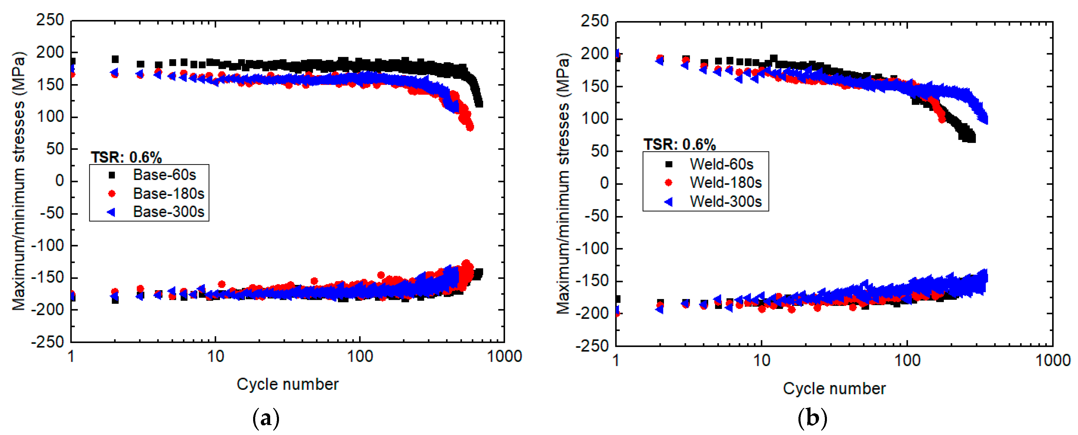
Figure 6 shows the maximum/minimum stresses as a function of cycle number. The creep-fatigue maximum/minimum stress paths were similar regardless of the duration of the tensile hold time. However, an increase of hold time slightly reduced the peak tensile stress. The steady-state stress was reached within 10 cycles and remained constant until the formation of a macro-crack or just prior to failure. The weldment’s graph in Figure 6b presents a higher maximum stress compared to that of the base metal’s graph. The base metal flow stress was more saturated than the weldments. For weldments and longer hold time condition, the maximum/minimum stresses did not achieve a saturation phase. Instead, the stress response was gradually decreased until failure.
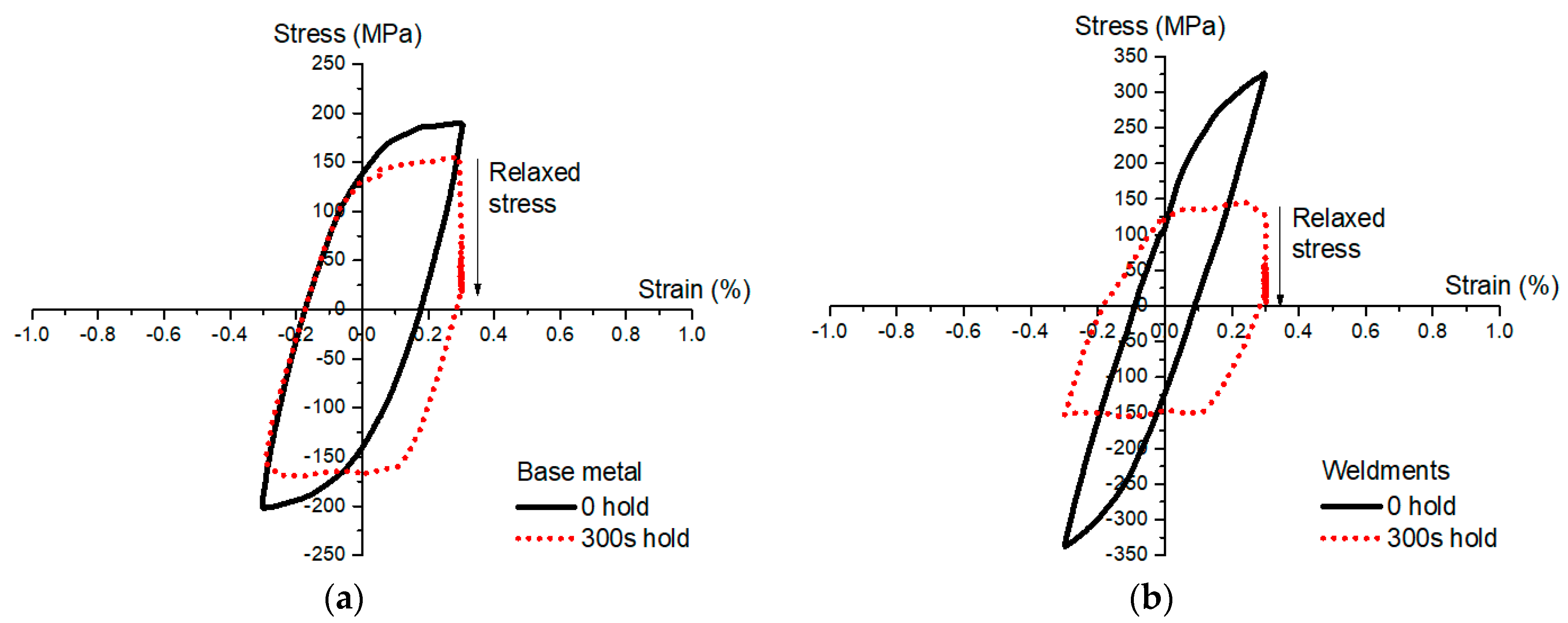
Low-cycle fatigue and creep-fatigue hysteresis loops for base metal and weldments at half-life are shown in Figure 7. The introduction of a hold time significantly increased the amount of inelastic strain as the hysteresis loop was increased in width. At all creep-fatigue tests, a rapid drop in peak stress (i.e., about 90% of initial stress level, approaching zero) was observed during the hold period at the maximum tensile strain. This rapid drop indicates a stress relaxation behavior for Alloy 617 during creep-fatigue loading. From this graph, it is found that the additional inelastic strain was introduced by means of transformation from elastic strain, caused by the reduction of stress generated during the holding time. Based on this behavior it can be assumed that there would be creep deformation at high temperature [10,19].
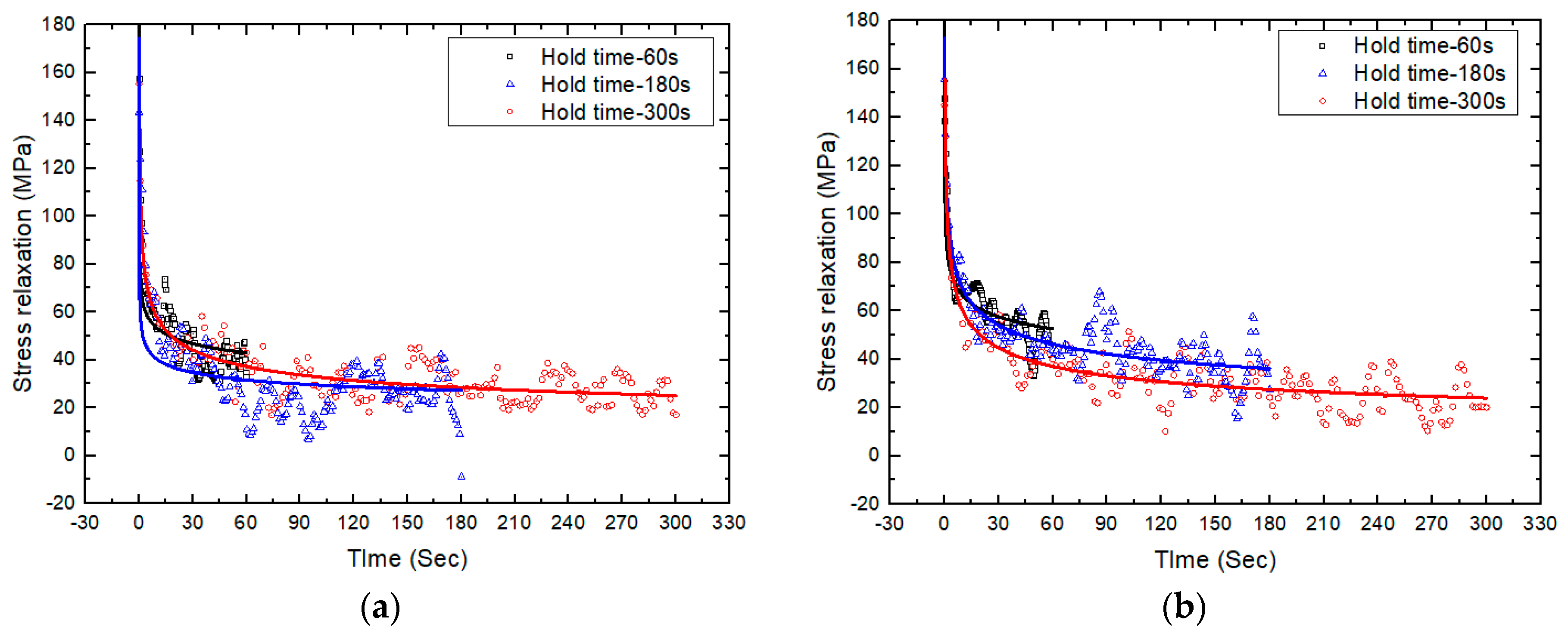
Figure 8 shows the stress relaxation curves for 60, 180, and 300 s hold time of base metal and weldments, respectively. The stress relaxation behavior of each holding time was at the same rate for the initial rapid stress drop. The increment of the hold time was found to significantly reduce the minimum stress in all cases. Regardless of the initial stress point, all of the stresses relaxed in a similar behavior. For the initial state, the stress rapidly decreased until approximately the 10 s point of the hold period, where it significantly reduced to 60% of the initial stress point. Meanwhile, the creep deformation mechanism occurred, which is indicated by the progressive stress drop. This relaxation of the stress response is due to the recovery process inside the crystals. During the tensile holding time, the creep mechanism restrained the rearrangement of the dislocation cells, decreased the dislocation density, coalesced the subgrain, and formed precipitations [17]. In fact, the existence of chromium carbides sometimes has the adverse effect of softening the structure by evolving the carbides at the creep temperature range.
Furthermore, the creep rate can be calculated from the slope at the stable state of stress relaxation behavior [9,16]. The Maxwell model is used as follows:
where ε(t) is the creep rate, E is the elastic modulus, and σr is the relaxed stress being measured. From the test results, it is obvious that the stress relaxation behavior was found to be time-dependent. The creep rate was calculated by means of best fitting, obtaining about 10−7/s and 10−6~10−7/s for base metal and weldments, respectively.
3.3. Crack Morphology
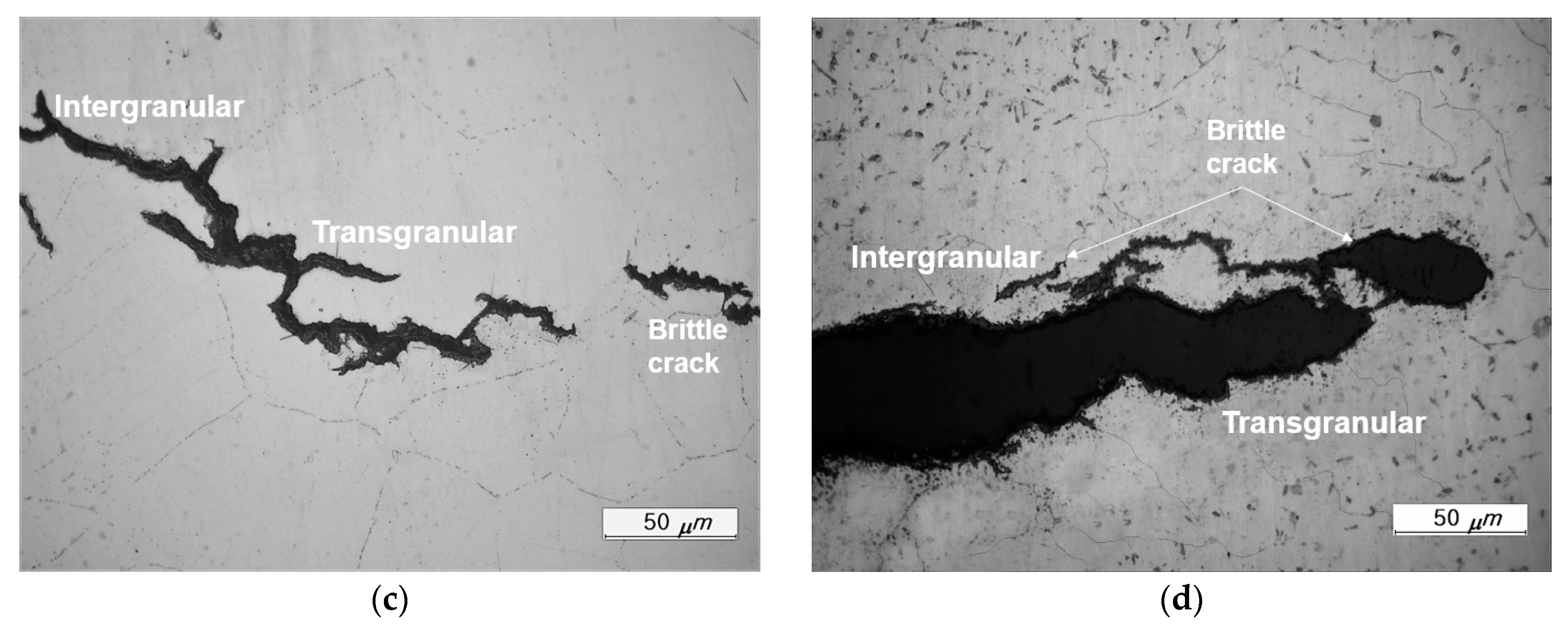
Creep-fatigue deformation is a combination of creep deformation and fatigue deformation at elevated temperatures. The creep-fatigue deformation involves the application of cyclic loading when the fatigue deformation/damage is enhanced by creep deformation/damage or vice versa. Generally, the creep-fatigue interaction (for peak tensile hold) is illustrated as a mixed-mode crack propagation of pure fatigue and creep cavities (develop independently) on the grain boundaries in the bulk material [9,11,16]. In this investigation, the selected creep-fatigue specimens were examined by using scanning electron microscopy (SEM) and optical microscopy (OM). Figure 9 shows typical crack morphologies of the tested specimens at 0.6% total strain range with 60 s holding time. The SEM micrographs in Figure 9a,b present typical intergranular cracks for base metal and weldments (indicated by the dotted rectangle and arrows). However, the tested specimens do not show any evidence of large creep round cavities at the grain boundaries. It has been reported for this alloy that the strengthening of γ′-precipitates provides a means of creep resistance [5,9,16]. Instead, the population of fine intergranular brittle cracks were observed near the crack tip, as shown in Figure 9c,d. It was found that those intergranular brittle cracks occurred due to the grain boundary embrittlement of M23C6 carbides.
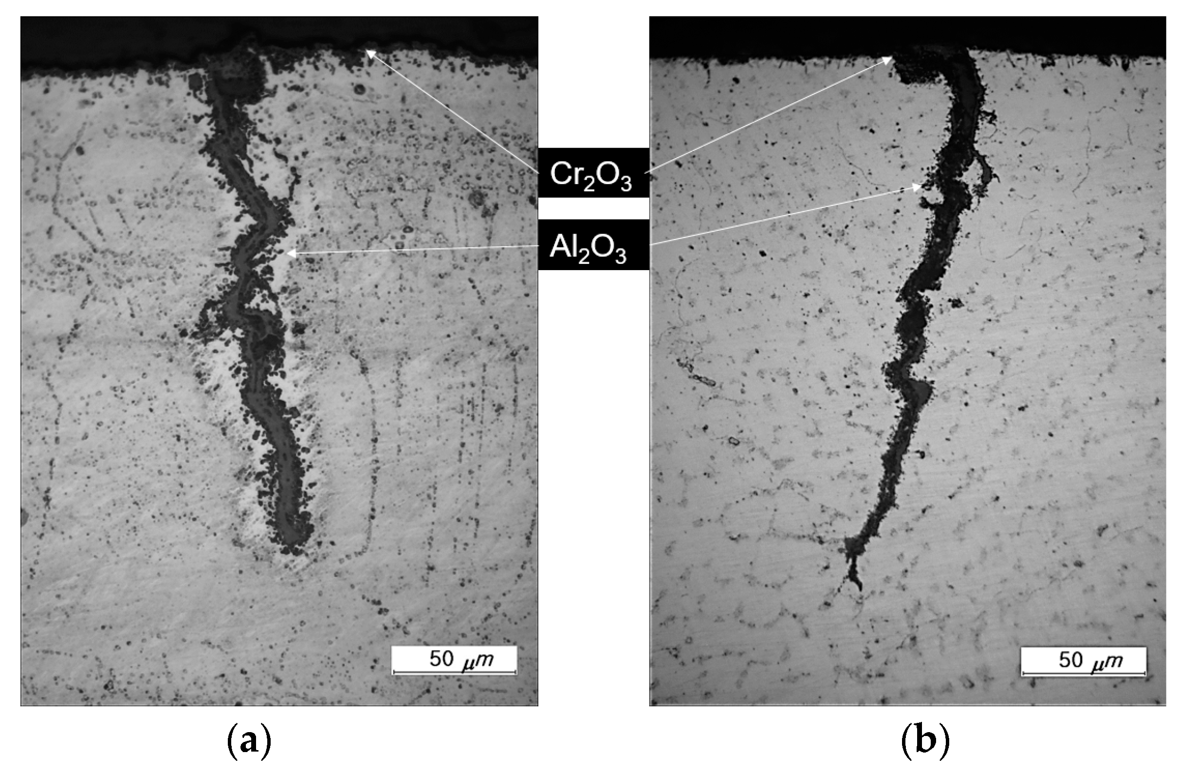
A massive amount of oxygen in high-temperature conditions is well-known to be involved in the oxidation attack in metal. The oxidation process is indeed a time-dependent behavior. Therefore, the addition of a hold time will result in the significant penetration depth of oxidation in the present investigation. Figure 10 shows typical oxidation breakdown in the tested specimen at 0.6% total strain range with 300 s holding time. The elemental composition result was obtained by energy dispersive spectroscopy (EDS); see [2]. The oxide surface layer was formed, consisting of a thick Cr-rich oxide layer and internal Al-rich oxide layer beneath the outer layer scale.
4. Linear Damage Summation
In the ASME Code, Section III, Subsection NH, creep-fatigue life is evaluated by a linear summation of fractions of cyclic damage and creep damage, schematically reported in some studies [19,20,21,22,23,24]. Thus, the creep-fatigue criterion is given by:
where Ncf and Nf are the cycle numbers in the creep-fatigue test and the low-cycle fatigue test with the same test condition, respectively. Δt and tr are the actual time at certain stress level and the allowable time to rupture at the corresponding stress level, respectively. Dtotal is the total allowable critical creep-fatigue damage fraction, where the total damage is usually assumed to be equal to one.
4.1. Fatigue and Creep Damage Calculations
In this creep-fatigue testing, the fatigue damage fraction, Df, is defined in terms of the ratio of cycle number under creep-fatigue condition, Ncf, to the cycle number under low-cycle fatigue condition, Nf, for the same type of material, total strain range, strain rate, and temperature as the creep-fatigue test. This formula can be expressed by:
The creep damage fraction, which is introduced during the peak tensile strain hold time, is equal to the damage rate formula as follows:
where Δt and tr are the actual time at a certain stress level and the allowable time to rupture at the corresponding stress level, respectively; dt is the incremental time interval at instantaneous stress, t is the strain hold time in one creep-fatigue cycle. The integration means integrating the creep damage produced during the strain hold time in one specific cycle (stable cycle), and calculation of this respective cycle to the multiplication of whole creep-fatigue life at 20% drop load in stress ratio as the cumulative creep damage. This requires the stress relaxation data at the respective cycle. Furthermore, the half-life cycle is assumed to be a stable cycle, which is estimated for one specific cycle.
In order to calculate the cumulative creep damage, the collected creep rupture data from Idaho National Laboratory (INL), Argonne National Laboratory (ANL), and Korean Atomic Energy Research Institute (KAERI) was adopted [6]. The best fitting curve was used for the calculation of rupture time corresponding to the varying stress levels in strain-controlled creep-fatigue tests. Furthermore, the correlation between the creep rupture time, temperature, and applied stress of Alloy 617 was extracted from the Larson–Miller equation as follows [25]:
where from 296 creep data of Alloy 617, the regression analysis of a second-order polynomial fit produced a correlation coefficient R2 = 0.9961; thus, the Larson–Miller coefficients were C = 17.39; a0 = 33,381; a1 = −5304.3; and a2 = −217.36, as in Equation (5). The creep rupture time, temperature, and stress are in units of hours, Kelvin, and MPa, respectively.
Since the stress was exponentially changed during the relaxation period, a constitutive equation is necessary to describe the stress relaxation behavior of materials. The stress relaxation curves during the strain hold for half life cycle were fitted to the power-law form in Equation (6). The fitting parameters were determined for each test. These parameters were used in the Equations (4) and (5) to evaluate the cumulative creep damage. An example of the power-law fit form to the stress relaxation part during the strain hold period is illustrated in Figure 11; see [5,10,15,16,20] for references.
where b0, b1, and t0 are regarded as fitting parameters, σ is stress in MPa, and t and t0 are the time during the hold which varies from 0 to the hold time and a constant that improves the fit (in seconds), respectively.
4.2. Creep-Fatigue Interaction Diagram
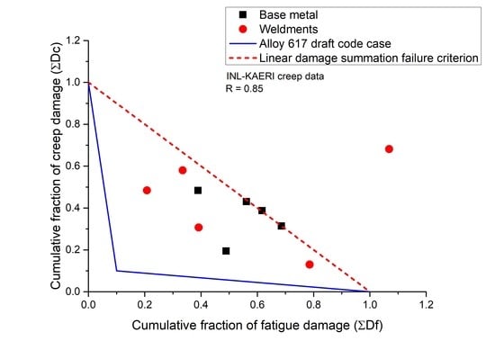
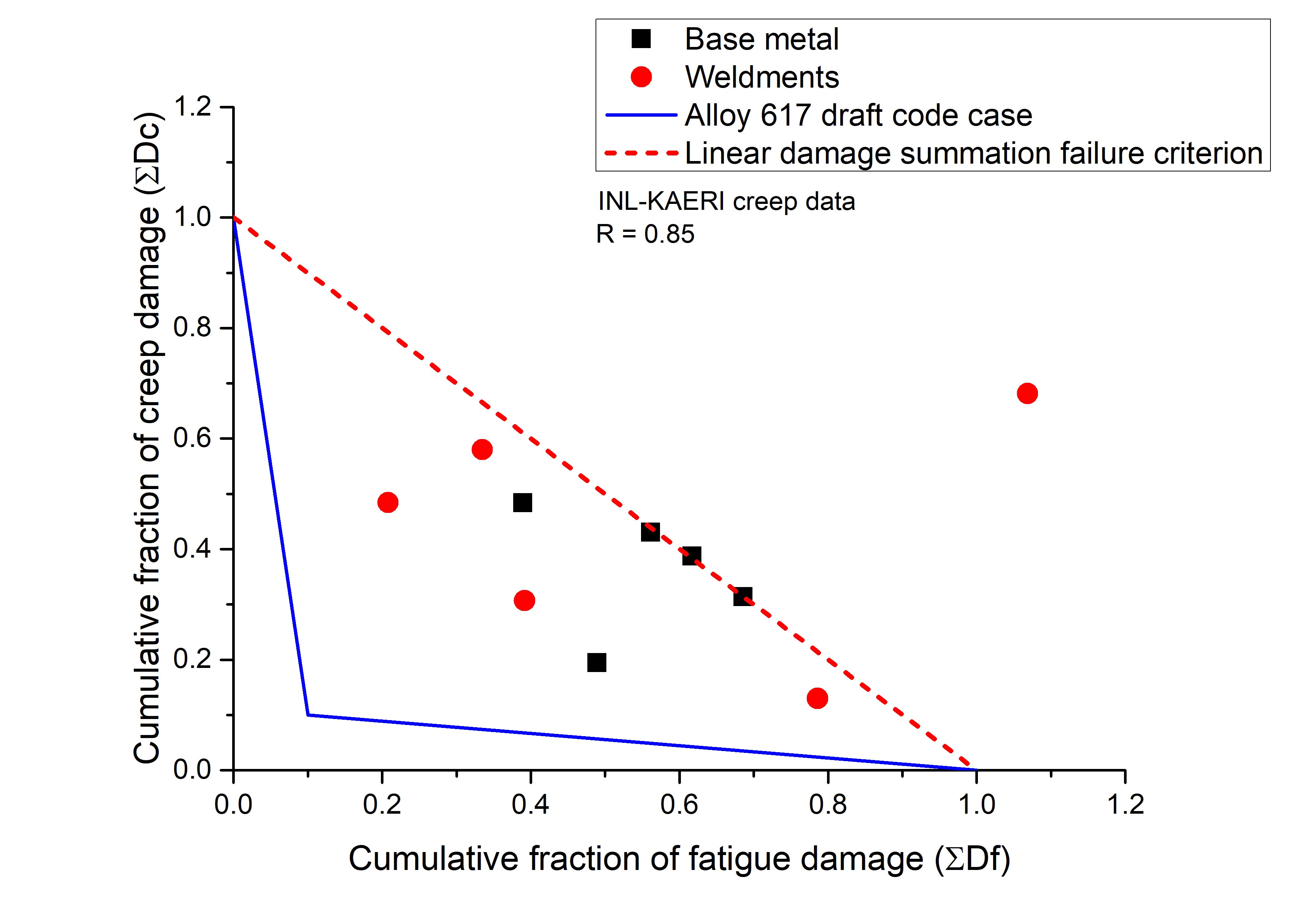
Figure 12 shows the creep-fatigue data points on the D-Diagram for base metal and weldments. Those data points were determined by means of linear damage summation method from the cumulative creep damage based on the Alloy 617 (base metal) creep-rupture data [6]. In this graph, the creep-fatigue margin from the Draft Alloy 617 Code Case (00320-21) was included, which has an intersection at coordinates (0.1, 0.1) as well as the linear damage summation failure criterion. The results show the domination of fatigue damage in the high total strain range, while the domination of creep damage was observed at the long holding time. The distance between the draft code case coordinates and the creep-fatigue damage data point describes the degree of creep-fatigue interaction. A short distance shows a strong combination of creep-fatigue interactions. For the creep-fatigue tests with low total strain range, the longer the hold time period is, the shorter the distance between the creep-fatigue damage data point and the draft code case coordinates. The bilinear blue line presents the failure criterion of the draft code case for Alloy 617. However, the linear damage summation method was not sufficient to determine the creep-fatigue life of Alloy 617 base metal and weldments because all the creep-fatigue damage data points were located above the draft code case line. Nevertheless, the red straight dashed line indicates the linear damage summation failure criterion. Additionally, most of the Alloy 617 base metal and weldments’ creep-fatigue data points are within this line.
4.3. Creep Damage for Weldments
As previously discussed, the total creep damage for weldments were calculated based on the Alloy 617 (base metal) creep rupture data. Therefore, the stress rupture factor should be adopted to overcome the situation between base metal and weldments. For example, the base metal and weldments may have a different stress level at the same rupture time. It can be mathematically explained that the stress required for weldments to rupture is equivalent to the rupture stress of the base metal multiplied by the stress rupture factor, R. The stress relaxation curves at the half life cycle showed that the weldment stress level was always higher than that of the base metal, which indicates R > 1. In this investigation, a stress rupture factor of 0.85 was used to generate the weldments’ creep damage, as reported in a previous work [15].
5. Discussion
High-temperature creep-fatigue tests were performed for base metal and weldments. Both materials showed a typical Coffin–Manson life dependence on inelastic strain range. Figure 5a shows Coffin–Manson curves of the base metal and weldment specimens. Those curves were used to determine the Coffin–Manson coefficients by using Equation (7):
where Δεin is the inelastic strain range at half-life, Nf is cycle number, and N and m are the fatigue ductility coefficient and the fatigue ductility exponent, respectively. The Coffin–Manson parameters were employed to measure the predicted creep-fatigue life, which requires less than 30% error of measurement. If the creep-fatigue life predicted by a Coffin–Manson relationship is at least within a factor of two (upper-lower bound) of the experimental life, this relationship is considered as a satisfactory method.
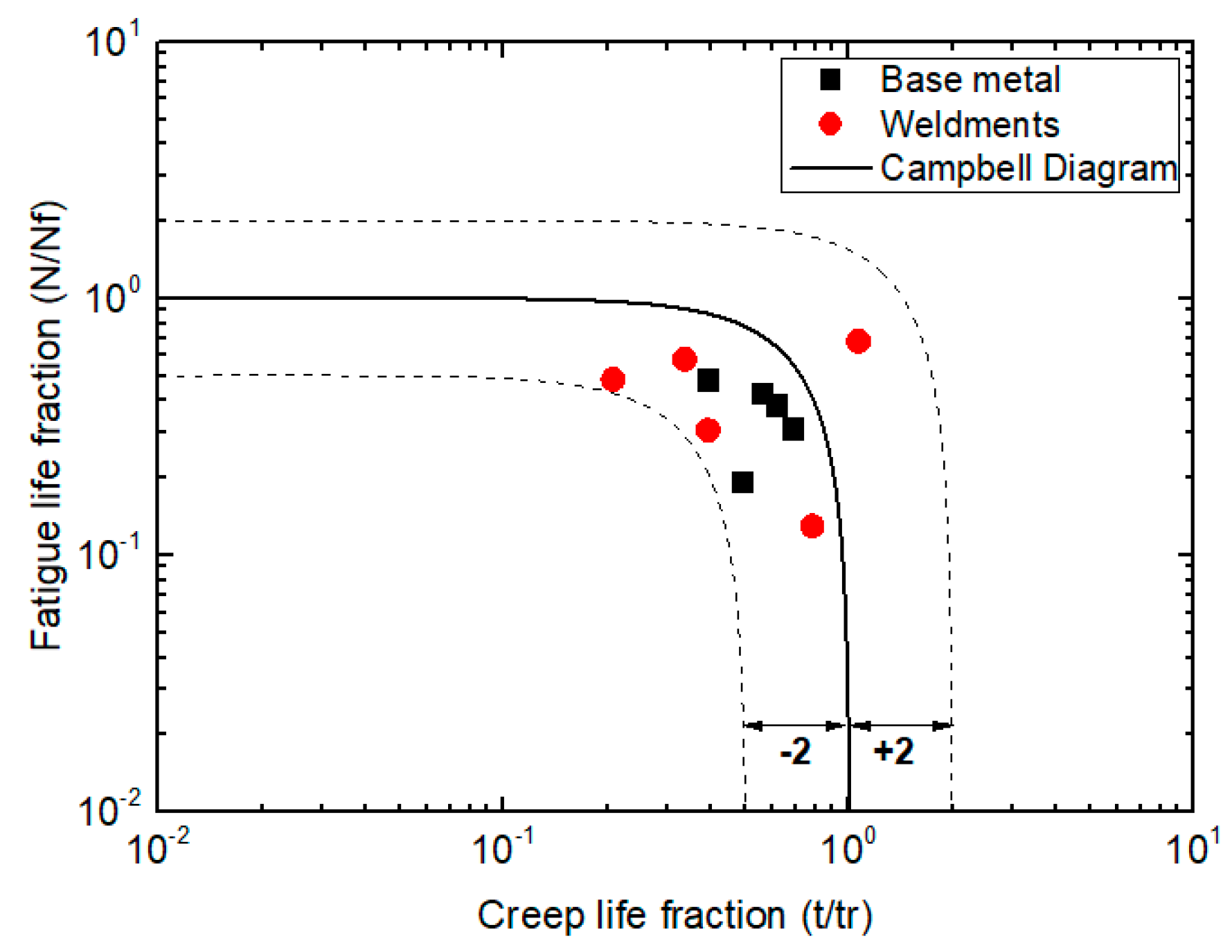
The linear damage summation method was used to identify which damage developed more rapidly until failure. The results shown in Figure 12 indicate that the creep and fatigue damage mechanism depend on the total strain range and hold time. When the lowest total strain range and the longest hold time were applied, the accumulative Dc per cycle was more significant. However, for some tests at higher total strain ranges, the cumulative creep-fatigue damage fraction was found to be greater than one (>1). It is worth noting that the Df is more severe at higher total strain ranges [19]. It was also observed that the Dc for most of the tests were higher than the ASME-accepted critical value (Dc) of 0.1, which indicates the potential suitability of this alloy for applications beyond 900 °C. In spite of the observed interaction diagram, Figure 13 shows that all of the test results are within the ±2 scatter band of the linear damage equation according to the Campbell diagram [22,26]. Therefore, the present investigation of the Alloy 617 base metal and weldments can still be represented using a linear damage summation method, as recommended in the ASME code at limited condition.
Following from the substitution of R = 0.85, the weldments’ data points were shifted nearly to the base metal data point set. Nevertheless, consider that only ≥1.2% of the total strain range data points were far below the failure criterion line of both base metal and weldments, which indicates that the problem may be with the high total strain range condition used in the present investigation rather than with the weldments specifically. Despite the fact that it was useful for accelerating the test, the high total strain range may have some issues for a weld in service. The creep-fatigue test for the weldments at low strain range condition generated data points more in line with those of the base metal and the damage margin in the D-Diagram. The application of a stress rupture factor of R ≤ 0.85 can improve the confidence for the weldments design with respect to the damage margin of the D-Diagram. However, a stress rupture factor of R ≥ 1.0 is not currently supported by the creep-rupture data [8,15,20].
None of the creep-fatigue test specimens failed in a pure fatigue mechanism. Intergranular brittle oxide cracks initiation and mixed-mode cracks propagation induced by fatigue slip could be seen on all tested specimens. In the case of weldments, all cracks were located in the weld metal region. The surface and sub-surface cracks mostly followed the interdendritic paths. In fact, the possible weakness of the weld metal was due to the presence of microstructural heterogeneity. The base metal structure has a stronger high-temperature deformation resistance due to its superior ductility given by the reinforcement of precipitates. Since the weldments are more brittle than the base metal, the difference in structure and properties between base metal and weldments involves a non-uniform local stress distribution [2]. Moreover, the residual stress effect from the welding process may generate a strain/stress concentration in the weld metal region, which becomes a preferential site of crack.
Based on the results, the addition of hold time tends to reduce the fatigue lifetime. The related time-dependent behavior of Alloy 617 at high temperature in air was mainly caused by environment interactions. One can assume that this creep-fatigue lifetime reduction is related to the crack initiation process. This might clarify why the longer test time has a lower cycle number, thus the oxide layer can grow more during this period. The existence of a brittle oxide layer may generate slip irreversibility. Precipitations were formed at the grain boundaries, which were an easy diffusion pathway for oxygen. When the breakdown of an oxide layer coalesced with the intergranular cracks at the grain boundaries, the oxidation damage started to develop rapidly. Consider that the growth of the surface chromia induced the development of a depleted area in the grain boundary carbides underneath the surface. A large number of oxidized cracks were also spotted at the specimen wall. It was noticed that the grain boundaries were either cracked or precipitated of branch-like alumina. Intergranular alumina precipitate is a very common case in air-oxidized Alloy 617, which is generated by the dissociation of chromia. Subsequently, the chromium oxide completely filled up the crack, which formed a large region of chromium oxide. Since this oxide particle is very brittle and has a low fracture strength, the oxidation caused and accelerated both the fatigue crack initiation and propagation. This hypothesis is related to the time-dependent intergranular cracking, which proves that the creep-fatigue lifetime is related to the high-temperature environment.
6. Conclusions
Creep-fatigue testing of Alloy 617 base metal and weldments at 900 °C has been completed. The high-temperature creep-fatigue behavior under different hold times was analyzed, and the application of linear damage summation was evaluated. The following conclusions can be drawn from the results:
- Under all creep-fatigue tests, the base metal indicated a superior creep-fatigue life to the weldments. It was noticed that the creep-fatigue life in the base metal was continually decreased by increasing the holding time. Otherwise, the effect of hold time on weldment life did not show a reduction at a longer hold time (>180 s), which indicates that the weldments were saturated at a relatively shorter holding time.
- The creep-fatigue lifetime was lower than that of the low-cycle fatigue lifetime. This result is due to the introduction of a hold time, which caused the amount of inelastic strain to increase as the stress was relaxed.
- The weldments cracks were located in the weld metal part due to the strain/stress concentration. However, there was not much difference between all creep-fatigue crack morphologies of the base metal and weldments. Fractography showed a combination of surface-connected intergranular brittle oxide cracks and mixed-mode cracks propagation induced by fatigue slip.
- The linear damage summation result shows that the fatigue damage was found to dominate at the higher total strain ranges, and the creep damage was dominated at a longer holding times. Although all of the damage fractions were higher than the ASME critical value of 0.1, those were still within the failure criterion for this Alloy. This method is promising because all of the damage fractions were within the ±2 scatter band of the linear damage equation according to the Campbell diagram.
Acknowledgments
This work was supported by a Research Grant of Pukyong National University (2017 year). The authors also would like to thank J.K. Wright from INL-USA and Woo-Gon Kim from KAERI-Korea for their data support and helpful discussions about this research.
Author Contributions
Seon Jin Kim and Rando Tungga Dewa formulated this research. Rando Tungga Dewa and Jeong Hun Park performed the experimental works. Rando Tungga Dewa and Seon Jin Kim interpreted the results, prepared, and submitted the manuscript for publication. Sang Yeol Lee contributed to the manuscript proof.
Conflicts of Interest
The authors declare no conflict of interest.
References
- Dewa, R.T.; Kim, S.J.; Kim, W.G.; Kim, E.S. Effect of strain range on the low cycle fatigue in Alloy 617 at high temperature. Metals 2017, 7, 54. [Google Scholar] [CrossRef]
- Dewa, R.T.; Kim, S.J.; Kim, W.G.; Kim, E.S. Understanding low cycle fatigue behavior of Alloy 617 base metal and weldments at 900 °C. Metals 2016, 6, 178. [Google Scholar] [CrossRef]
- Wright, J.K.; Carroll, L.J.; Cabet, C.; Lillo, T.M.; Benz, J.K.; Simpson, J.A.; Lloyd, W.R.; Chapman, J.A.; Wright, R.N. Characterization of elevated temperature properties of heat exchanger and steam generator alloys. Nucl. Eng. Des. 2012, 251, 252–260. [Google Scholar] [CrossRef]
- Totemeier, T.C.; Tian, H. Creep-fatigue-environment interactions in INCONEL 617. Mater. Sci. Eng. A 2007, 468–470, 81–87. [Google Scholar] [CrossRef]
- Carroll, L.; Carroll, M. Creep-Fatigue Behavior of Alloy 617 at 850 and 950 °C. Available online: https://www.osti.gov/scitech/servlets/purl/1084680 (accessed on 24 November 2015).
- Wright, J.K.; Lillo, T.M.; Wright, R.N.; Kim, W.G.; Sah, I.J.; Kim, E.S.; Park, J.Y.; Kim, M.H. Creep and creep-rupture of Alloy 617. Nucl. Eng. Des. 2017, in press. [Google Scholar] [CrossRef]
- Rao, K.B.S.; Meurer, H.P.; Schuster, H. Creep-fatigue interaction of lnconel 617 at 950 °C in simulated nuclear reactor helium. Mater. Sci. Eng. A 1988, 104, 37–51. [Google Scholar] [CrossRef]
- Totemeier, T.C. High-temperature creep-fatigue of Alloy 617 base metal and weldments. In Proceedings of the Eighth International Conference on Creep and Fatigue at Elevated Temperatures, San Antonio, TX, USA, 22–26 July 2007; Volume 9, pp. 255–260. [Google Scholar]
- Carroll, L.J.; Cabet, C.; Carroll, M.C.; Wright, R.N. The development of microstructural damage during high temperature creep-fatigue of a nickel alloy. Int. J. Fatigue 2013, 47, 115–125. [Google Scholar] [CrossRef]
- Chen, X.; Yang, Z.; Sokolov, M.A.; Erdman, D.L.; Mo, K.; Stubbins, J.F. Effect of creep and oxidation on reduced fatigue life of Ni-based alloy 617 at 850 °C. J. Nucl. Mater. 2014, 444, 393–403. [Google Scholar] [CrossRef]
- Holdsworth, S. Creep-fatigue failure diagnosis. Materials 2015, 8, 7757–7769. [Google Scholar] [CrossRef] [PubMed]
- Kojima, M.; Funai, M.; Dozaki, T.; Watanabe, O.; Matsuda, A. Effect of strain rate and hold time in creep-fatigue test. In Proceedings of the ASME Pressure Vessels and Piping Conference 2013, Paris, France, 14–18 July 2013; Volume 6A. [Google Scholar]
- Lu, Y.L.; Chen, L.J.; Wang, G.Y.; Benson, M.L.; Liaw, P.K.; Thompson, S.A.; Blust, J.W.; Browning, P.F.; Bhattacharya, A.K.; Aurrecoechea, J.M.; et al. Hold time effects on low cycle fatigue behavior of HAYNES 230 superalloy at high temperatures. Mater. Sci. Eng. A 2005, 409, 282–291. [Google Scholar] [CrossRef]
- Fournier, B.; Sauzay, M.; Caes, C.; Noblecourt, M.; Mottot, M.; Bougault, A.; Rabeau, V.; Pineau, A. Creep-fatigue-oxidation interactions in a 9Cr-1Mo martensitic steel. Part I: Effect of tensile holding period on fatigue lifetime. Int. J. Fatigue 2008, 30, 649–662. [Google Scholar] [CrossRef]
- Wright, J.K.; Carroll, L.J.; Wright, R.N. Creep and Creep-Fatigue of Alloy 617 Weldments. Available online: http://www.osti.gov/scitech/biblio/1168621 (accessed on 16 September 2015).
- Cabet, C.; Carroll, L.; Wright, R. Low cycle fatigue and creep-fatigue behavior of Alloy 617 at high temperature. J. Press. Vessel Technol. 2013, 135, 061401. [Google Scholar] [CrossRef]
- Carroll, M.C.; Carroll, L.J. Developing dislocation subgrain structures and cyclic softening during high-temperature creep-fatigue of a nickel alloy. Metall. Mater. Trans. A 2013, 44A, 3592–3607. [Google Scholar] [CrossRef]
- ASTM International. ASTM E2714-13, Standard Test Method for Creep-Fatigue Testing; ASTM International: West Conshohocken, PA, USA, 2013. [Google Scholar]
- Kolluri, M.; ten Pierick, P.; Bakker, T. Characterization of high temperature tensile and creep-fatigue properties of Alloy 800H for intermediate heat exchanger components of (V)HTRs. Nucl. Eng. Des. 2015, 284, 38–49. [Google Scholar] [CrossRef]
- Wright, J.K.; Carroll, L.J.; Sham, T.L.; Lybeck, N.J.; Wright, R.N. Determination of the creep-fatigue interaction diagram for Alloy 617. In Proceedings of the ASME Pressure Vessels and Piping Conference 2016, Vancouver, BC, Canada, 17–21 July 2016; Volume 5. [Google Scholar]
- Chen, X.; Sokolov, M.A.; Sham, S.; Erdman, D.L.; Busby, J.T.; Mo, K.; Stubbins, J.F. Experimental and modeling results of creep-fatigue life of Inconel 617 and Haynes 230 at 850 °C. J. Nucl. Mater. 2013, 432, 94–101. [Google Scholar] [CrossRef]
- Zhang, X.; Tu, S.T.; Xuan, F. Creep-fatigue endurance of 304 stainless steels. Theor. Appl. Fract. Mech. 2014, 71, 51–66. [Google Scholar] [CrossRef]
- Cabrillat, M.; Allais, L.; Mottot, M.; Riou, B.; Escaravage, C. Creep fatigue behavior and damage assessment for Mod 9Cr 1Mo steel. In Proceedings of the ASME Pressure Vessels and Piping Conference 2006, Vancouver, BC, Canada, 23–27 July 2006; Volume 6, pp. 511–520. [Google Scholar]
- Skelton, R.P.; Gandy, D. Creep-fatigue damage accumulation and interaction diagram based on metallographic interpretation of mechanisms. Mater. High Temp. 2008, 25, 27–54. [Google Scholar] [CrossRef]
- Wright, J.K.; Lillo, T.L. Progress Report on Alloy 617 Time-Dependent Allowable Stresses. Available online: www.osti.gov/servlets/purl/1236836 (accessed on 4 July 2017).
- Nazmy, M.Y. Sequential effect of creep and fatigue in a cast Ni-base alloy. Scr. Metall. 1982, 16, 823–826. [Google Scholar] [CrossRef]
Figure 1.
Optical micrograph of Alloy 617. Containing weld metal, heat-affected zone (HAZ), and base metal region. Carbides are seen along the grain boundary.
Figure 1.
Optical micrograph of Alloy 617. Containing weld metal, heat-affected zone (HAZ), and base metal region. Carbides are seen along the grain boundary.
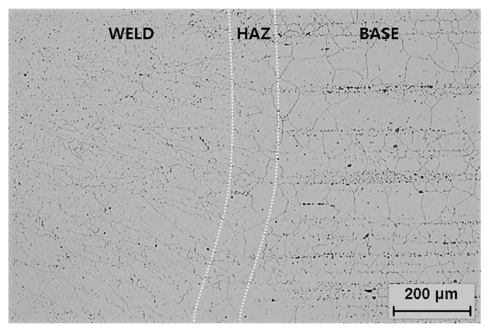
Figure 2.
(a) Weld pad configuration; (b) Geometry of the cylindrical button-head specimen for creep-fatigue test (all units in mm).
Figure 2.
(a) Weld pad configuration; (b) Geometry of the cylindrical button-head specimen for creep-fatigue test (all units in mm).

Figure 3.
Schematic diagram of typical loading waveform for pure low-cycle fatigue test: (a) Strain–time; (b) Stress–time; (c) Stress–strain curves; and creep-fatigue test with tension hold time: (d) Strain–time; (e) Stress–time; (f) Stress–strain curves.
Figure 3.
Schematic diagram of typical loading waveform for pure low-cycle fatigue test: (a) Strain–time; (b) Stress–time; (c) Stress–strain curves; and creep-fatigue test with tension hold time: (d) Strain–time; (e) Stress–time; (f) Stress–strain curves.
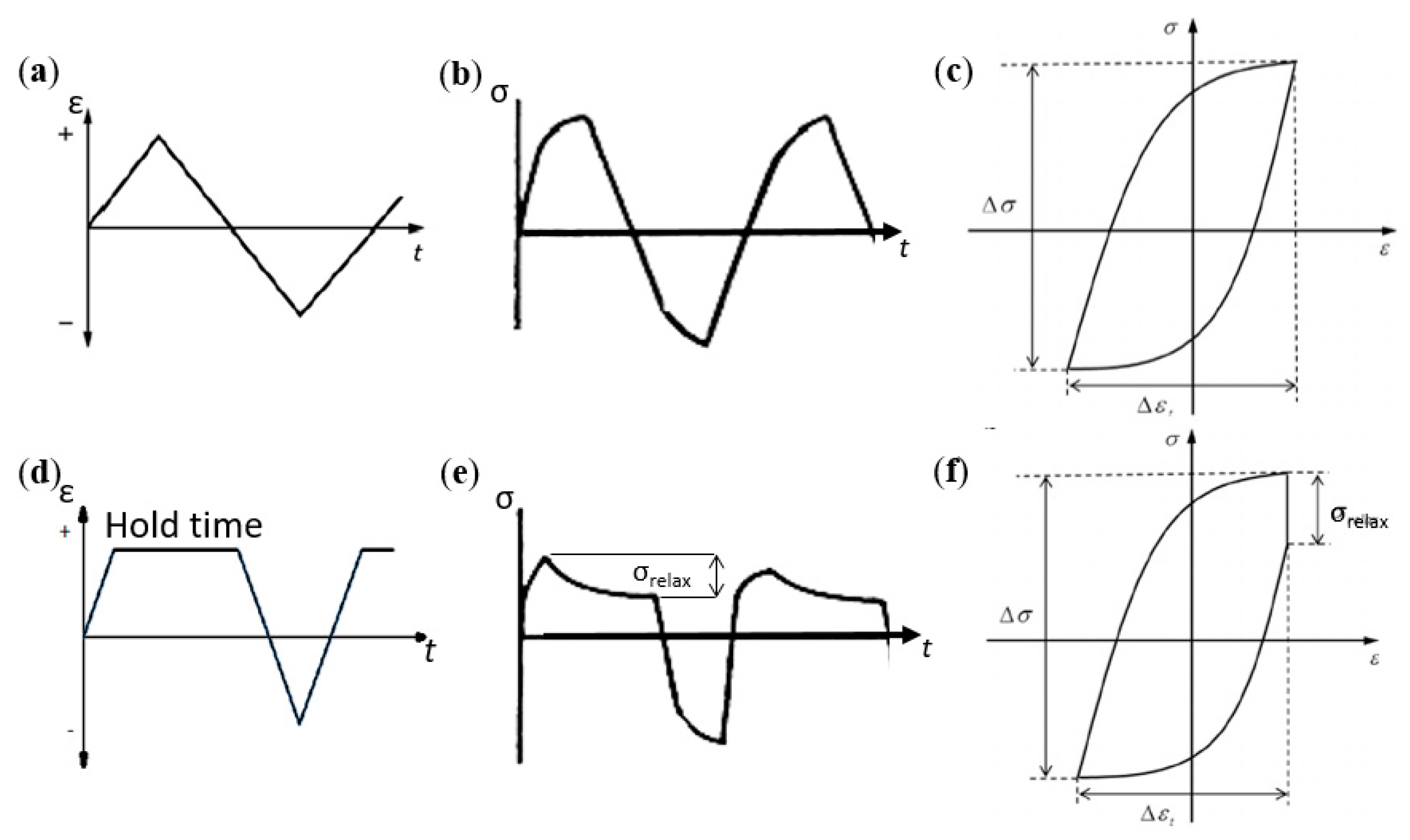
Figure 4.
Tensile curves of Alloy 617 base metal and weldment at 900 °C.
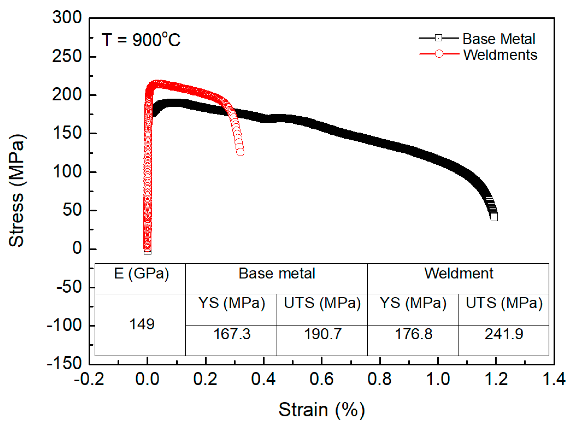
Figure 5.
Creep fatigue life curves as a function of: (a) Total strain range; (b) Tensile hold time.
Figure 5.
Creep fatigue life curves as a function of: (a) Total strain range; (b) Tensile hold time.

Figure 6.
Maximum/minimum stresses vs. cycle number curves of Alloy 617: (a) Base metal; (b) Weldments.
Figure 6.
Maximum/minimum stresses vs. cycle number curves of Alloy 617: (a) Base metal; (b) Weldments.

Figure 7.
Hysteresis loops for low-cycle fatigue and creep-fatigue of Alloy 617: (a) Base metal; (b) Weldments.
Figure 7.
Hysteresis loops for low-cycle fatigue and creep-fatigue of Alloy 617: (a) Base metal; (b) Weldments.

Figure 8.
The stress relaxation vs. time curves of Alloy 617: (a) Base metal; (b) Weldments.

Figure 9.
Typical crack morphologies of tested specimens for Alloy 617 tested at 0.6% total strain range with 60 s holding time. SEM micrographs: (a) Base metal; and (b) Weldments. Optical micrographs: (c) Base metal; and (d) Weldments.
Figure 9.
Typical crack morphologies of tested specimens for Alloy 617 tested at 0.6% total strain range with 60 s holding time. SEM micrographs: (a) Base metal; and (b) Weldments. Optical micrographs: (c) Base metal; and (d) Weldments.
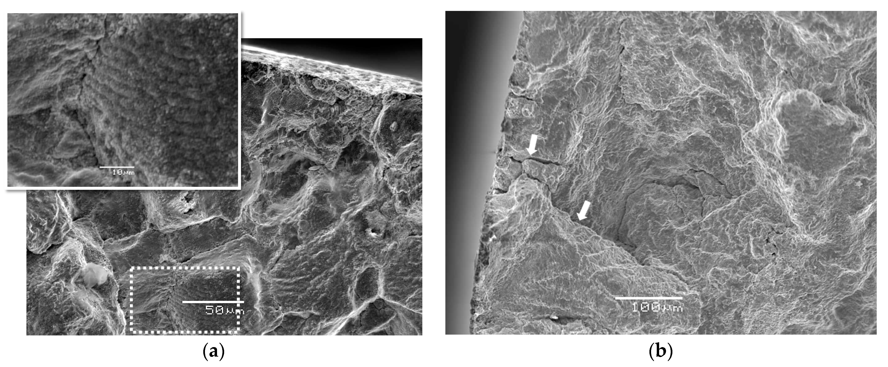

Figure 10.
Surface cracking in creep-fatigue-tested specimens at 0.6% total strain range with 300 s holding time, showing breakdown of brittle-oxide cracking for: (a) Base metal; and (b) Weldments.
Figure 10.
Surface cracking in creep-fatigue-tested specimens at 0.6% total strain range with 300 s holding time, showing breakdown of brittle-oxide cracking for: (a) Base metal; and (b) Weldments.

Figure 11.
Power-law fit form to the stress relaxation part of Alloy 617 base metal during hold time.
Figure 11.
Power-law fit form to the stress relaxation part of Alloy 617 base metal during hold time.
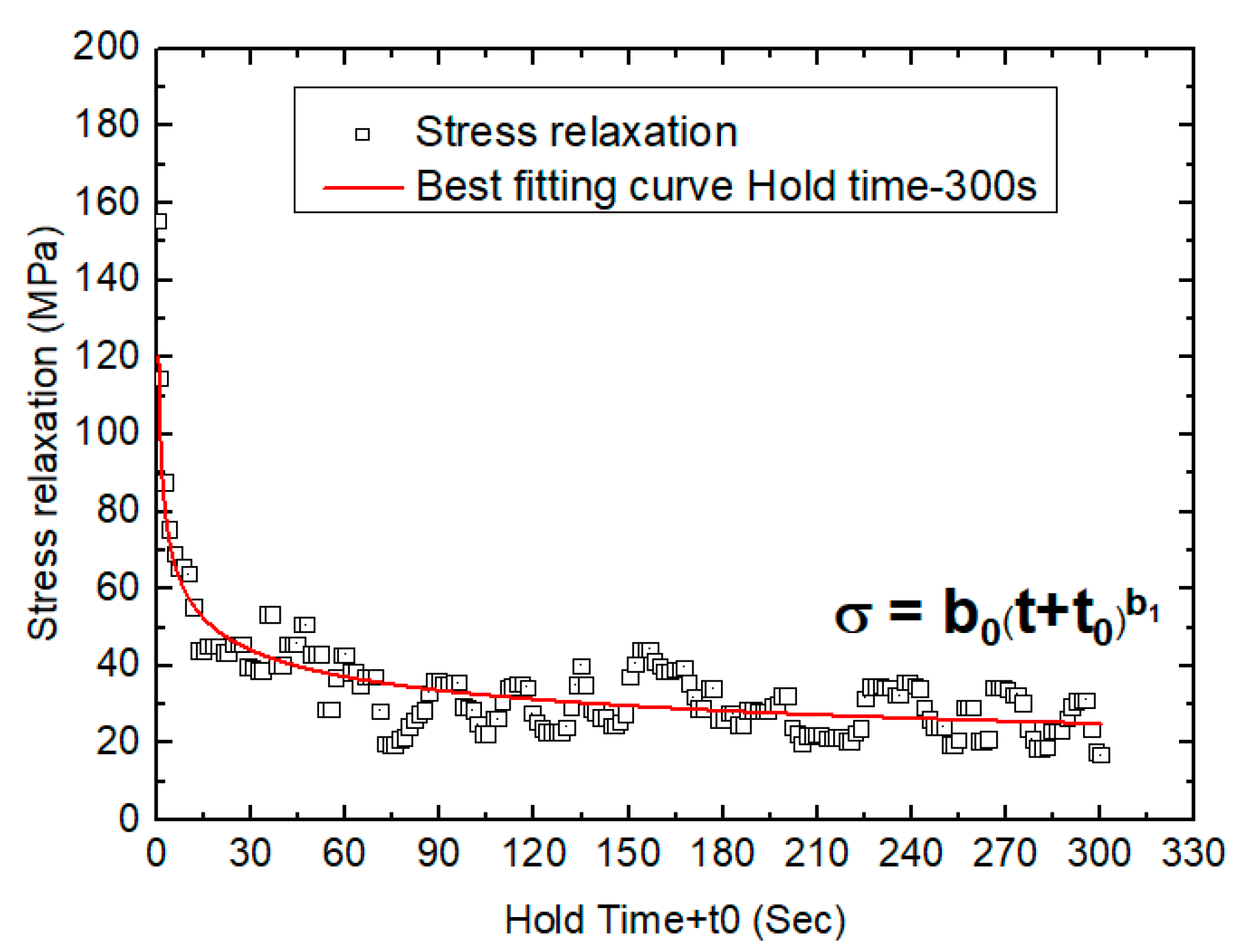
Figure 12.
Creep-fatigue interaction diagram based on linear damage summation showing the cumulative fraction of creep vs. fatigue damage of Alloy 617. Red dashed line shows the ideal failure criterion of linear damage summation and the bilinear blue line is the failure criterion of the draft code case for Alloy 617.
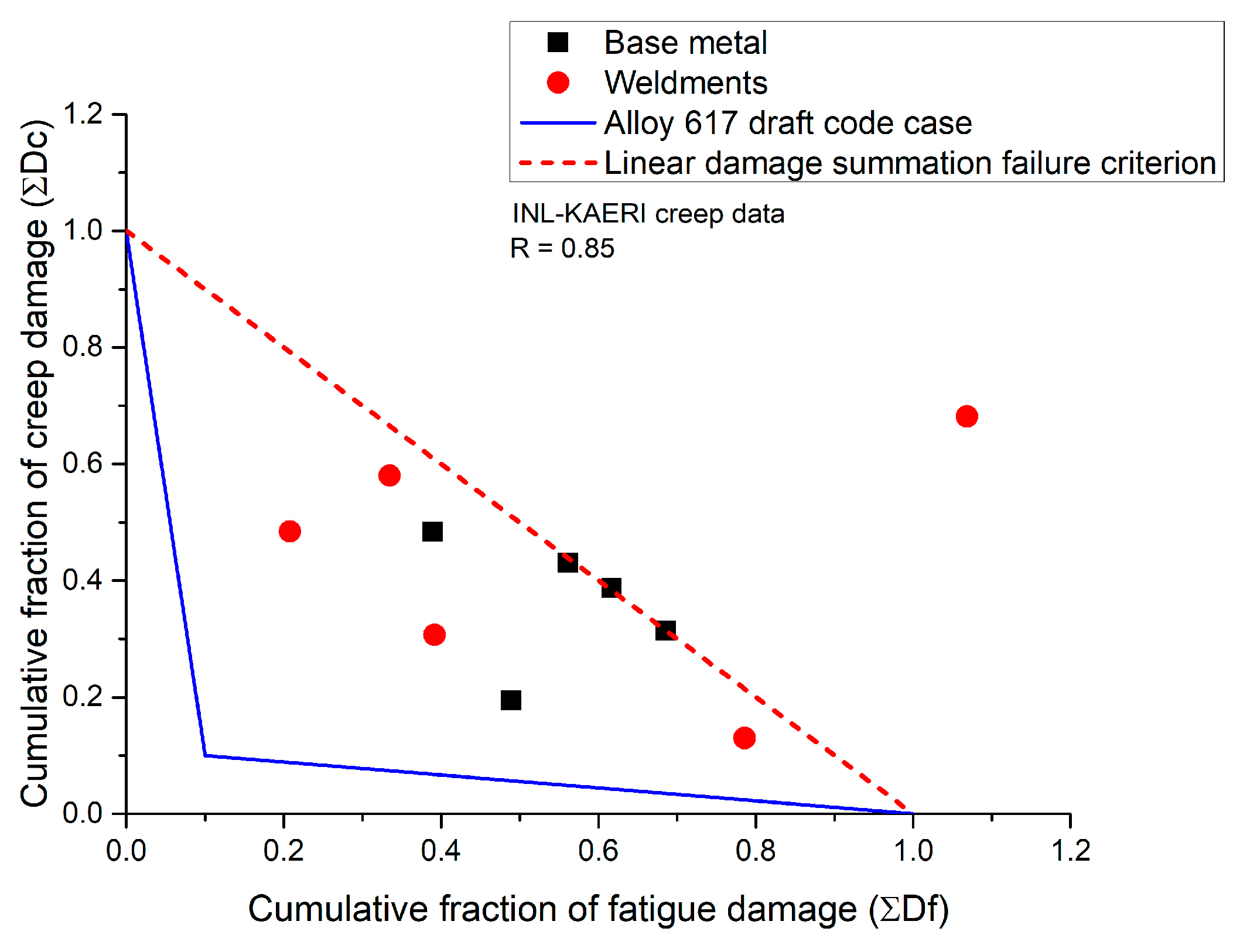
Figure 13.
Logarithmic representation of creep-fatigue life interaction based on linear damage summation and its margin line of ±2 scatter band.
Figure 13.
Logarithmic representation of creep-fatigue life interaction based on linear damage summation and its margin line of ±2 scatter band.


Table 1.
The chemical composition (wt %) of the commercial-grade Alloy 617 and its filler wire.
| Material | C | Ni | Fe | Si | Mn | Co | Cr | Ti | P | S | Mo | Al | B | Cu |
|---|---|---|---|---|---|---|---|---|---|---|---|---|---|---|
| Alloy 617 | 0.08 | 53.11 | 0.949 | 0.084 | 0.029 | 12.3 | 22.2 | 0.41 | 0.003 | <0.002 | 9.5 | 1.06 | <0.002 | 0.027 |
| KW-T617 | 0.07 | Bal | 0.33 | 0.3 | 0.3 | 11.29 | 22.5 | 0.42 | <0.003 | 0.001 | 8.8 | 1.1 | - | <0.01 |
Table 2.
Low-cycle fatigue and creep-fatigue test results completed at 900 °C.
| Sample-ID | ∆εt (%) | Hold Time (s) | Inelastic Strain Range, ∆εin/2 (%) | Stress Amplitude, ∆σ/2 (MPa) | Cycle Number 1 | Time to Failure (h) |
|---|---|---|---|---|---|---|
| Weld-01 | 0.6 | 0 | 0.088 | 331.3 | 827 | 2.76 |
| Weld-1 | 0.6 | 60 | 0.220 | 161.3 | 277 | 5.54 |
| Weld-2 | 0.6 | 180 | 0.238 | 163.6 | 172 | 9.17 |
| Weld-3 | 0.6 | 300 | 0.240 | 156.4 | 339 | 29.4 |
| Weld-04 | 1.2 | 0 | 0.364 | 375.1 | 190 | 4.43 |
| Weld-4 | 1.2 | 60 | 0.510 | 169.0 | 203 | 4.73 |
| Weld-05 | 1.5 | 0 | 0.502 | 386.5 | 140 | 3.5 |
| Weld-5 | 1.5 | 60 | 0.665 | 178.5 | 110 | 2.75 |
| Base-01 | 0.6 | 0 | 0.176 | 193.5 | 1179 | 3.93 |
| Base-1 | 0.6 | 60 | 0.235 | 175.52 | 662 | 13.24 |
| Base-2 | 0.6 | 180 | 0.235 | 157.3 | 577 | 30.77 |
| Base-3 | 0.6 | 300 | 0.232 | 156.6 | 459 | 39.78 |
| Base-04 | 1.2 | 0 | 0.470 | 186.2 | 487 | 11.36 |
| Base-4 | 1.2 | 60 | 0.519 | 166.6 | 334 | 7.79 |
| Base-05 | 1.5 | 0 | 0.625 | 181.2 | 405 | 10.13 |
| Base-5 | 1.5 | 60 | 0.668 | 165.6 | 250 | 6.25 |
1 Cycle number was determined from a 20% drop in the stress ratio.
© 2018 by the authors. Licensee MDPI, Basel, Switzerland. This article is an open access article distributed under the terms and conditions of the Creative Commons Attribution (CC BY) license (http://creativecommons.org/licenses/by/4.0/).
Share and Cite
MDPI and ACS Style
Dewa, R.T.; Park, J.H.; Kim, S.J.; Lee, S.Y. High-Temperature Creep-Fatigue Behavior of Alloy 617. Metals 2018, 8, 103. https://doi.org/10.3390/met8020103
AMA Style
Dewa RT, Park JH, Kim SJ, Lee SY. High-Temperature Creep-Fatigue Behavior of Alloy 617. Metals. 2018; 8(2):103. https://doi.org/10.3390/met8020103
Chicago/Turabian StyleDewa, Rando Tungga, Jeong Hun Park, Seon Jin Kim, and Sang Yeol Lee. 2018. "High-Temperature Creep-Fatigue Behavior of Alloy 617" Metals 8, no. 2: 103. https://doi.org/10.3390/met8020103
Note that from the first issue of 2016, this journal uses article numbers instead of page numbers. See further details here.