Slurry Erosion Behavior of AlxCoCrFeNiTi0.5 High-Entropy Alloy Coatings Fabricated by Laser Cladding


1
College of Mechanics and Materials, Hohai University, Nanjing 210098, China
2
College of Mechanical and Electrical Engineering, Hohai University, Changzhou 213022, China
*
Authors to whom correspondence should be addressed.
Metals 2018, 8(2), 126; https://doi.org/10.3390/met8020126
Submission received: 7 January 2018
/
Revised: 4 February 2018
/
Accepted: 5 February 2018
/
Published: 11 February 2018
(This article belongs to the Special Issue Complex Concentrated Alloys (CCAs) - Current Understanding and Future Opportunities)
Abstract
:High-entropy alloys (HEAs) have gained extensive attention due to their excellent properties and the related scientific value in the last decade. In this work, AlxCoCrFeNiTi0.5 HEA coatings (x: molar ratio, x = 1.0, 1.5, 2.0, and 2.5) were fabricated on Q345 steel substrate by laser-cladding process to develop a practical protection technology for fluid machines. The effect of Al content on their phase evolution, microstructure, and slurry erosion performance of the HEA coatings was studied. The AlxCoCrFeNiTi0.5 HEA coatings are composed of simple face-centered cubic (FCC), body-centered cubic (BCC) and their mixture phase. Slurry erosion tests were conducted on the HEA coatings with a constant velocity of 10.08 m/s and 16–40 meshs and particles at impingement angles of 15, 30, 45, 60 and 90 degrees. The effect of three parameters, namely impingement angle, sand concentration and erosion time, on the slurry erosion behavior of AlxCoCrFeNiTi0.5 HEA coatings was investigated. Experimental results show AlCoCrFeNiTi0.5 HEA coating follows a ductile erosion mode and a mixed mode (neither ductile nor brittle) for Al1.5CoCrFeNiTi0.5 HEA coating, while Al2.0CoCrFeNiTi0.5 and Al2.5CoCrFeNiTi0.5 HEA coatings mainly exhibit brittle erosion mode. AlCoCrFeNiTi0.5 HEA coating has good erosion resistance at all investigated impingement angles due to its high hardness, good plasticity, and low stacking fault energy (SFE).
1. Introduction
Slurry erosion (SE) is a serious concern for hydraulic turbines and other fluid machines due to silt entrained in water flow, especially in the Yellow River regions of China. Slurry erosion results in the surface degradation of flow components of hydroturbine equipment and reduces all efficiency [1,2]. Hydraulic turbine equipment generally made of mild steel, white cast iron or stainless steel. However, these materials are considerably less resistant to erosive wear. It is important to develop new erosion-resistant materials. Recently, high-entropy alloys (HEAs) have attracted extensive attention due to their versatile combinations including high strength and hardness, good thermal stability, excellent corrosion and wear resistance [3,4,5,6]. These characteristics make them suitable candidates for structural and functional materials. The main method of preparing high-entropy alloys is vacuum arc melting and then casting [7,8]. As the formation of simple solid solution phase requires high cooling rate, the shape and size of bulk ingots prepared by arc-melting technique are limited. Meanwhile, this preparation method causes high production cost due to many expensive metals such as Ni, Co, and Cr being contained in HEAs. Therefore, some researchers have been turning to explore the effective and economical HEA coating on the low-cost metallic substrate.
Compared to the other processing techniques such as magnetron sputtering, electrochemical deposition, and plasma arc cladding, laser cladding can be used to deposit coatings with thickness more than 1 mm, which is more beneficial for engineering applications. In addition, the coatings can be deposited in a few steps, which eliminates the influence of the substrate and allows gradual composition and property changes through the coating thickness [9]. These favorable advantages have made the laser-cladding alloy attractive among surface modification technologies. Huang et al. [10] prepared TiVCrAlSi HEA coatings on Ti-6Al-4V substrate by laser cladding and investigated the dry sliding wear behavior. The combination of the hard (Ti,V)5Si3 phase and relatively ductile and tough BCC matrix improved the sliding wear resistance. Yue et al. [11] studied the solidification behavior in laser cladding of AlCoCrCuFeNi high-entropy alloy on magnesium substrates using the Kurz-Giovanola-Trivedi and the Gaümann models. Except for some Cu rejected into the Mg melt, no serious dilution of the HEA composition occurred in the top layer of the coating. This is considered to be important because any dilution of the HEA composition with Mg would likely decrease the corrosion resistance of the HEA. Kunce et al. [12] produced the AlCoCrFeNi high-entropy thin-walled samples using the laser engineered net shaping (LENS) technology. The effect of the cooling rate during solidification on the microstructure of the alloy was studied through different laser-scanning rates. It was found that with an increasing in the laser-scanning rate during the solidification process, the average grain size of the alloy decreased. Vickers microhardness increases with the decrease of the average grain size. AlCoCrFeNiTi alloy system has been investigated in bulk state. Zhou et al. [13] studied the microstructure and strengthening mechanism of theAlCoCrFeNiTi0.5 alloy. For AlCoCrFeNiTi0.5 alloy, its super-high strength and good plasticity were attributed to its microstructure of intrinsic strong body-centered cubic solid solution, and effective multiple strengthening mechanisms such as solid solution strengthening, precipitation strengthening, and nano-composite strengthening effects, etc. Jiao et al. [14] studied the superior mechanical properties of AlCoCrFeNiTix High-Entropy Alloys upon dynamic loading. They found that the ultimate strength and fracture strain of AlCoCrFeNiTix alloys are superior to most of bulk metallic glasses and in situ metallic glass matrix composites. However, the slurry erosion properties of AlxCoCrFeNiTi0.5HEA coatings have been rarely studied. In this article, AlxCoCrFeNiTi0.5 HEA coatings with different Al content were fabricated by laser cladding. The effects of Al addition on the microstructure and slurry erosion wear behavior were investigated. It is necessary for practical industrial applications.
2. Experimental Procedure
2.1. Material
As-received Q345 steel plate with dimensions of 25 × 40 × 10 mm3 was used as the substrate material. The substrate was sandblasted to remove surface contaminants and increased the absorption of laser energy. The AlxCoCrFeNiTi0.5 HEA coatings(x: molar ratio, denoted as Al1.0, Al1.5, Al2.0 and Al2.5 alloy, respectively) were prepared in this study by laser cladding. The HEA powder used in the experiment had a high purity (more than 99.5%) with a mesh size of 200–300. The mixed powders with the aid of a high-energy ball milling equipment were pre-placed on the steel specimens with a thickness of approximate 300–400 μm using PVA (Shanghai Zengye Industrial Co., Ltd., Shanghai, China) as a binder. The samples were dried in a vacuum oven (Nanjing Huanke Testing Equipment Co., Ltd., Nanjing, China) at 100 °C for 1h prior to laser cladding. Laser cladding was carried out using an EFW-300 type YAG pulsed laser (Guangda Laser Technology Co., Ltd., Shenzhen, China), which was equipped with a four-axis numerical control working table. With a series of optimization trial runs, the optimized process parameters were obtained: laser power 2.5 kW, laser beam spot diameter 1.2 mm, scanning velocity 1.5 mm·s−1, pulse frequency 20 Hz, pulse width 2.5 ms. High-purity argon gas at a flow rate 5 L·min−1 was used as ash ielding gas to prevent oxidation during the cladding experiment. A 50% overlap condition for multi-tracking was employed. Three layers high-entropy alloys were deposited under the same processing parameter.
After laser cladding, metallographic and erosion samples with dimensions of 10 × 10 × 10 mm3 were cut by electrical sparkle machining. All samples were ground and polished using abrasive papers down to 1200 grit size to obtain a smooth surface. Samples of microstructural observation were etched with alcohol dilute aqua regia. The top surface microstructure was investigated by scanning electron microscopy (SEM, JSM-6360, JEOL Ltd., Tokyo, Japan). The phase composition of HEA coatings was identified by X-ray diffraction (XRD) with a D/max-2550 diffractometer (Rigaku Corporation, Tokyo, Japan) using Cu Ka radiation. The top surface and cross-section morphology of the HEA coatings was examined by SEM. The microhardness of the polished surface of the HEA coatings was performed by a Vickers hardness tester (HXD-1000TC, Shanghai Optical Instrument Factory, Shanghai, China) at a load of 200 g and 15 s loading time. The average of five points was reported for each sample.
2.2. Slurry Erosion Test
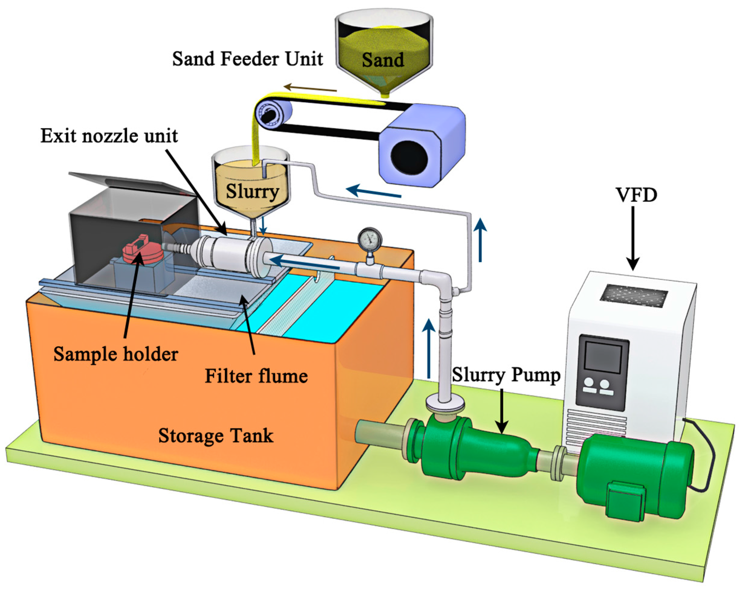
Slurry erosion test was performed using man-made jet type rig shown in Figure 1. The test rig provides the flexibility to regulate experiment parameters such as impingement angle, sand concentration, working media and impact velocity. The velocity of the slurry jet is controlled by changing the frequency of the motor converter used for driving the pump. The sand concentration is adjusted by changing the rotation speed of driving motor. The test parameters used for the slurry erosion experiment are shown in Table 1. Irregular sand particles in the size range of 16–40 mesh were used for slurry erosion studies. Slurry with a concentration of 10 kg/m3 and 30 kg/m3 was prepared using sand obtained from the Yangtze River Delta. The main composition of river sand is SiO2. Each sample was tested for 30 min with a cycle time of 5 min. In this study, the distance is 6 cm between the tested specimen and the ejector nozzle. The erosion samples were cleaned thoroughly with industrial acetone solution to remove contaminants and dried. A precision balance to an accuracy level of 0.1 mg was used to measure the mass loss before and after the test at regular intervals. The erosive wear rate is calculated based on the cumulative mass loss of sample with time, i.e., mg·min−1. The eroded surface characterization was examined by SEM. For comparison, 00Cr16Ni5Mo alloy (denoted as Cr16 alloy), widely used to fabricate various hydraulic turbine components, was tested under the same erosion condition.
3. Results
3.1. Microstructure and XRD Analysis
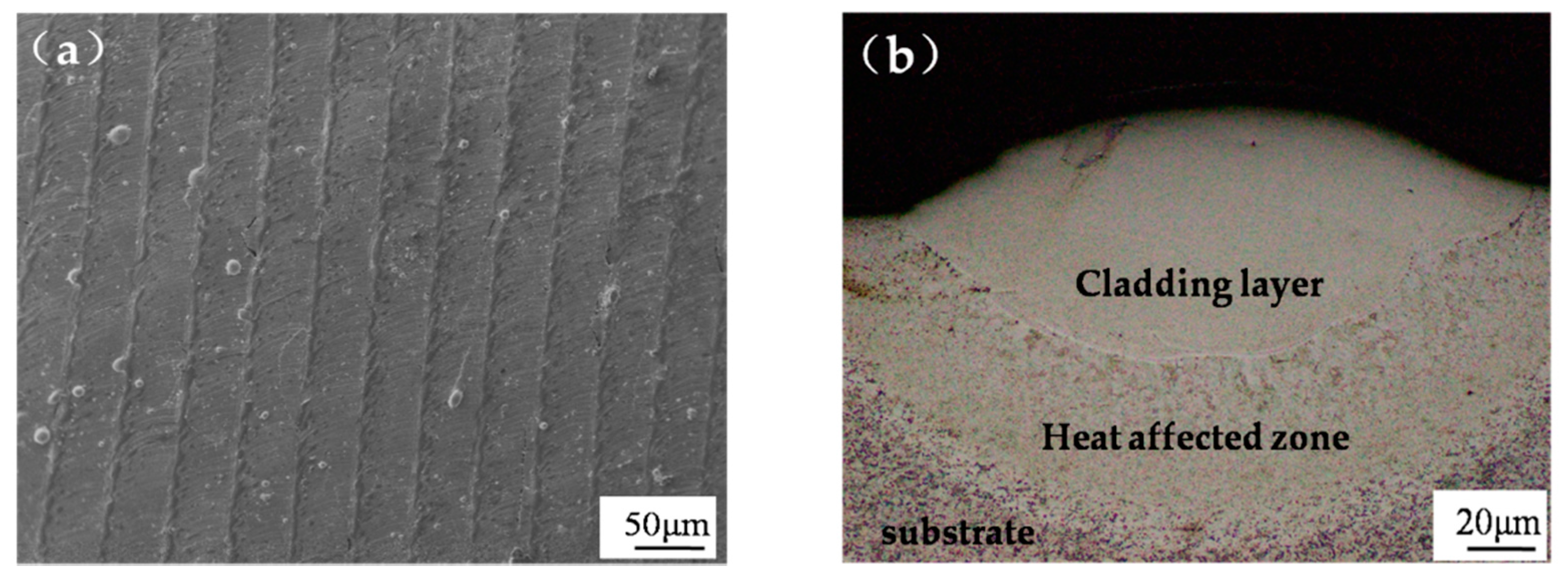
The laser-cladding process parameters have great influence on the quality, microstructure, and properties of the HEA coatings. With the aforementioned optimized parameter, AlCoCrFeNiTi0.5 HEA coating with few pores could be formed on Q345 substrate as is shown in Figure 2a. It is obvious from Figure 2a that the HEA coating exhibits a typical fish scale lap structure. Figure 2b shows the cross-section SEM image of AlCoCrFeNiTi0.5 single-track coating. The bonding line shows a curved shape, rather than a straight line, indicating a good metallurgical bond between the cladding layer and the substrate, which is favorable for the mechanical performance of the coating.
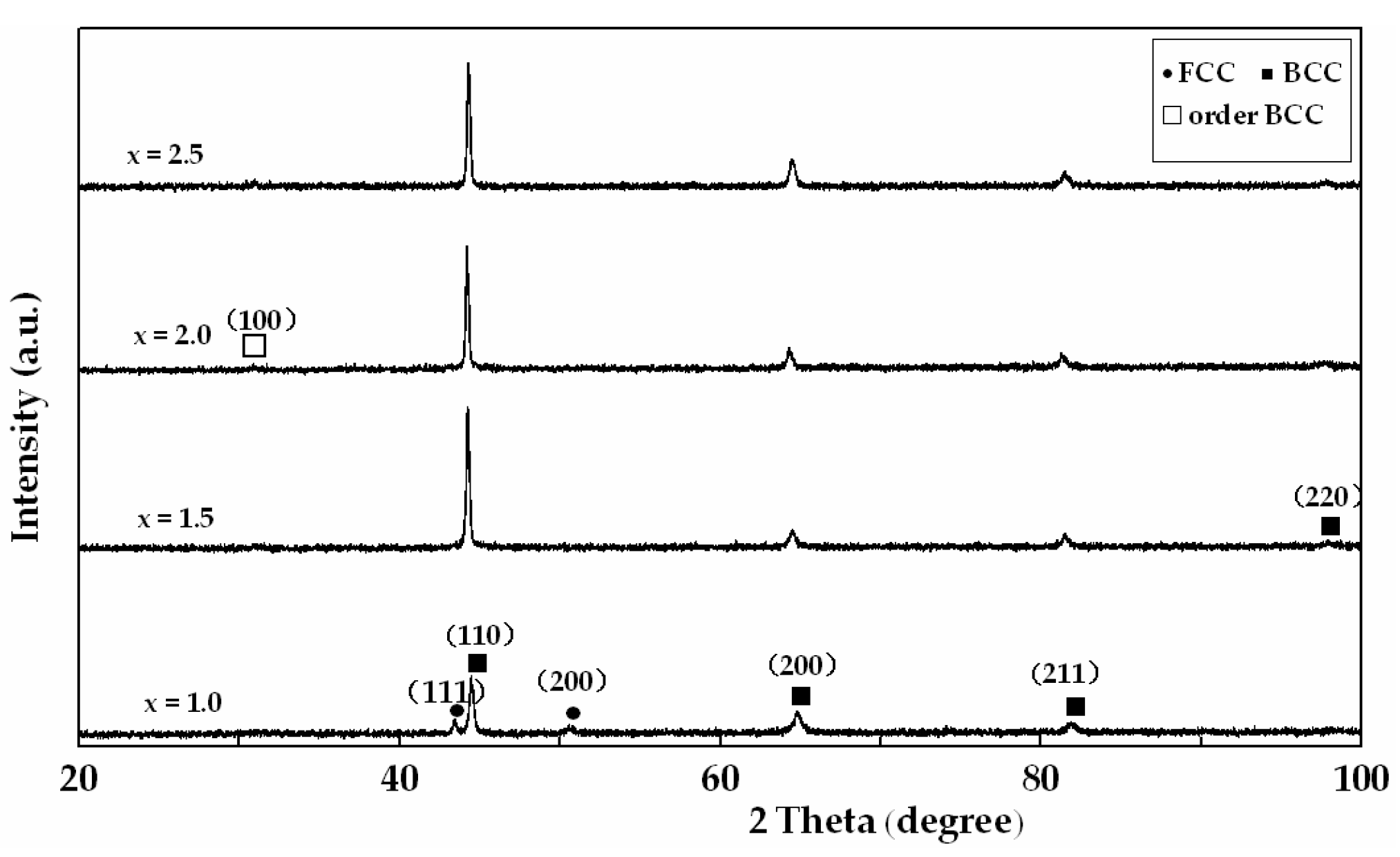
The XRD patterns of AlxCoCrFeNiTi0.5 HEA coatings with different Al content are shown in Figure 3. As can be seen, the AlxCoCrFeNiTi0.5 HEA coatings exhibit only simple solid solution structure, specifically face-centered cubic (FCC), body-centered cubic (BCC) and their mixture due to the effect of high mixing entropy [15]. A mixture of FCC + BCC crystal structure is observed in Al1.0HEA alloy. The relative intensity of (110)B peak increases and FCC peak disappears in Al1.5HEA alloy. The reflection shift can be partially attributed to the difference of local topologies between FCC and BCC structures [16]. Al has a larger metallic radius, compared with several transition cluster elements such as Co, Cr, Fe, Ni. The increase in the lattice constant with increasing the Al content indicates a corresponding larger lattice-strain effect. To relax the lattice distortion, the metastable FCC phase prefers to transform to a relatively stabilized BCC structure as the Al content in the alloy is increased. Only two BCC phases can be detected in the XRD pattern of the Al2.0 and Al2.5 HEA alloys. Compared with the XRD pattern of the Al1.5 HEA alloy, a minor order BCC peak appears in the Al2.0 and Al2.5 HEA alloys. The order BCC phase in AlxCoCrFeNiTi0.5 alloy system has been confirmed as NiAl-based intermetallic (IM) phase [17]. The XRD results show that Al addition exhibits a remarkable influence on the phase composition of the AlxCoCrFeNiTi0.5 HEA alloy.
Figure 4 shows Vickers hardness as a function of Al content. The hardness of the AlxCoCrFeNiTi0.5 HEA coatings exhibited a strong correlation with their aluminum content and phase structure. This suggests that the formation of a BCC type structure is a dominant factor of hardening, and the increase of the relative amount of BCC phase leads to a large increase in hardness. The larger atomic radius, the transformation of the crystal structure and dispersion of nanocrystallite could be responsible for the increased hardness of the alloys [18]. The microhardness of the HEA coatings in this work can reach 667.3 to 801.1 HV, which is at least 1.8 times that of 00Cr16Ni5Mo alloy (370.5 HV).
Figure 5 presents the SEM images of the AlxCoCrFeNiTi0.5HEA top surface layers. The typical microstructure consists of dendritic (DR) and interdendritic (ID) as a result of faster nucleation and solidification. With the addition of Al content, the solidification structure varies from columnar dendrite to non-equiaxed dendrite grain, and finally to equiaxed dendrite grain. The Al1.0 alloy shows the morphology of columnar dendrite and minor non-equiaxed dendrite. When Al content reaches x = 1.5, the columnar phase dissolves and single non-equiaxed dendrite appears, which is consistent with the XRD result. The Al2.0 and Al2.5HEA alloys exhibit the same equiaxed dendrite structure. The morphology features indicate the Al2.0 and Al2.5HEA alloys should have similar phase composition and solidification behavior.
3.2. Results of Slurry Erosion Tests
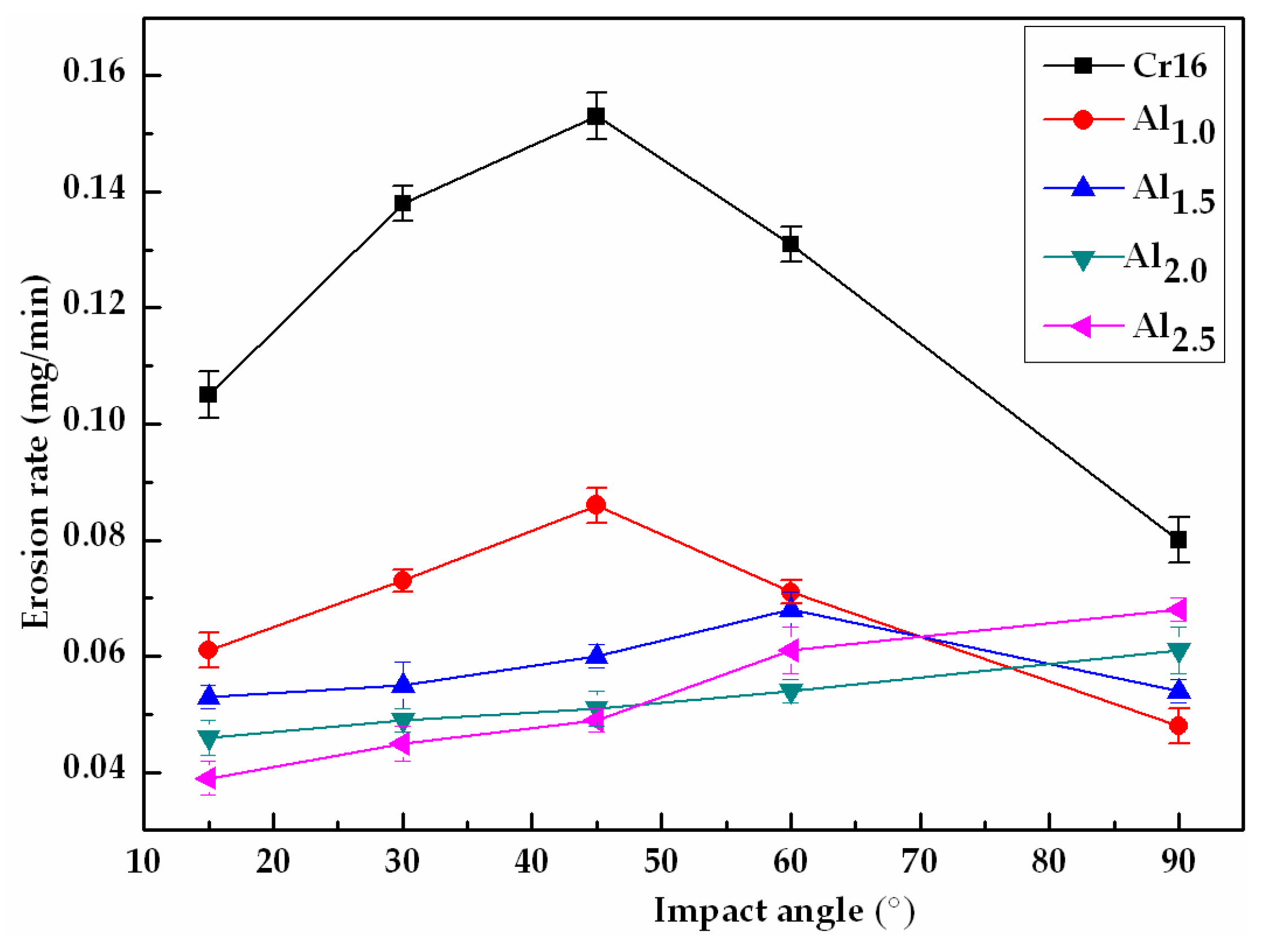
Figure 6 displays the erosion rate of AlxCoCrFeNiTi0.5 HEA coatings and Cr16 alloy as a function of impingement angle after erosion for 30 min. The Al1.0 HEA coating and Cr16 alloy showed the maximum erosion rate at 45°, then the erosion rate decreasing gradually with the impingement angle, which is consistent with the theory of the ductile mode of erosion behavior [19,20]. The erosion rate of the Al1.5 HEA coating approached a maximum at 60° and then decreased at 90°. It showed a mixture mode of erosion behavior. In case of the Al2.0 and Al2.5 HEA coatings, the erosion rate increased monotonically with the impingement angle and arrived at its maximum value at 90° impingement angle, which exhibits the brittle mode of erosion behavior [21]. It is evident from Figure 6 that the Al1.0 HEA coating showed smaller erosion rate in comparison with Cr16 alloy at all the investigated impingement angles. The erosion rate of Al1.0 HEA coating is 1.78 times lower than Cr16 alloy at 45° impingement angle and 1.68 times lower at 90° impingement angle. The reason behind the high erosion resistances of the Al1.0 HEA coating at low impingement angles (from 15° to 45°) is thought to be its higher hardness compared to theCr16 alloy. In slurry erosion wear, the effect of slurry scouring makes the deformation lips or convex bodies easy to be washed away, which results in the more important role of the hardness of target material at a low angle of impingement. At normal impingement angle (90°), the Al1.0 and Al1.5 HEA coatings still showed significantly lower erosion rate than Cr16 alloy. However, the erosion rate for the Al2.0 and Al2.5 HEA coatings was similar to theCr16 alloy. Closed to normal impingement, ductility and toughness play a more dominant role [22]. Al1.0 HEA alloy, whose yield stress, fracture strength, and plastic strain are as high as 2.26 GPa, 3.14 GPa, and 23.3%, respectively, has the super comprehensive mechanical properties even superior to most of the high-strength alloys such as bulk metallic glasses [23]. It would result in less erosion rate at normal impingement angle. The second possible reason is that Al1.0 and Al1.5 HEA alloys have lower stacking fault energy (SFE) compared to theCr16 alloy. A decrease of SFE results in an increase of work hardening capability of the material, thereby lowering the material removal rate [24]. Using a combination of discrete Fourier transform (DFT) calculation and XRD analysis, Zaddach et al. [25] reported the SFE of the equiatomic NiFeCoCr alloy to be approximate 20 mJ/m2, whereas SFE is of the order of 70–80 mJ/m2 for Cr16 stainless steel [26]. With the Al content increasing, the AlxCoCrFeNiTi0.5HEA coatings showed a transition from the ductile erosion mode to the brittle erosion mode. Limited plasticity likely affects the erosion wear resistance, so the Al2.0 and Al2.5 HEA coatings with higher hardness as well as bigger brittleness can reduce the erosion wear resistance at normal impingement.
The slurry erosion behavior of AlxCoCrFeNiTi0.5 HEA coatings and Cr16 alloy with sand concentration at 45° and 90° impingement angle is presented in Figure 7. It can be observed that the erosion rates of the test material increased nonlinearly with the increase in the sand concentration, although the percent of the increase is not same for different alloys. Higher sand concentration allows a larger number of sand particles to impact on the surface of the wear specimen, which leads to increase the erosion rate of the material. It is also clear that although sand concentration was increased to 3 times, the erosion rate did not show a similar response. This could be explained by the fact that the shield effect caused by the collisions between the incoming and rebounding particles [27]. Only a portion of particles actually impacts on the target surface while the others lose their way to target surface owing to the interaction between the incoming and rebounding particles. These findings are studied in detail by many researchers [28,29,30]. For pot-and centrifugal-type impingement experimental rigs, the correlation between erosion rates and sand concentration is highly nonlinear in nature. Some of the investigators have observed the adverse effect of concentration on erosion rate [31,32]. Moreover, as the impingement angle was higher (α = 90°), the shield zone was higher, and therefore the percent increase of erosion rate for the same material at 45° impingement angle is higher than that at 90° impingement angle.
The slurry erosion behavior of AlxCoCrFeNiTi0.5 HEA coatings and Cr16 alloy with time is shown in Figure 8. The results clearly indicate that the erosion rate of specimens was relatively high during the early cycles with some exceptions, and attained a steady state after 15th or 20th min of testing. Comparison with solid particle erosion, slurry erosion has not obvious incubation period. Similar trends were reported by other researchers [2,33]. The relatively stable erosion rate shows erosion time has no effect on the wear mechanism noticeably during the impingement process. The high erosion rate in the initial stage may be attributed to the initial rough surface of the specimens. The existence of micro-peaks and valleys on the surface of the specimens might have resulted in higher material removal rate during the initial period [34]. The second reason may be work hardening owing to the ductility of sample surface subjected to the repeated impact of sand particles, which results in less material removal and thus reduces the erosion rate.
3.3. Observation of Eroded Surfaces
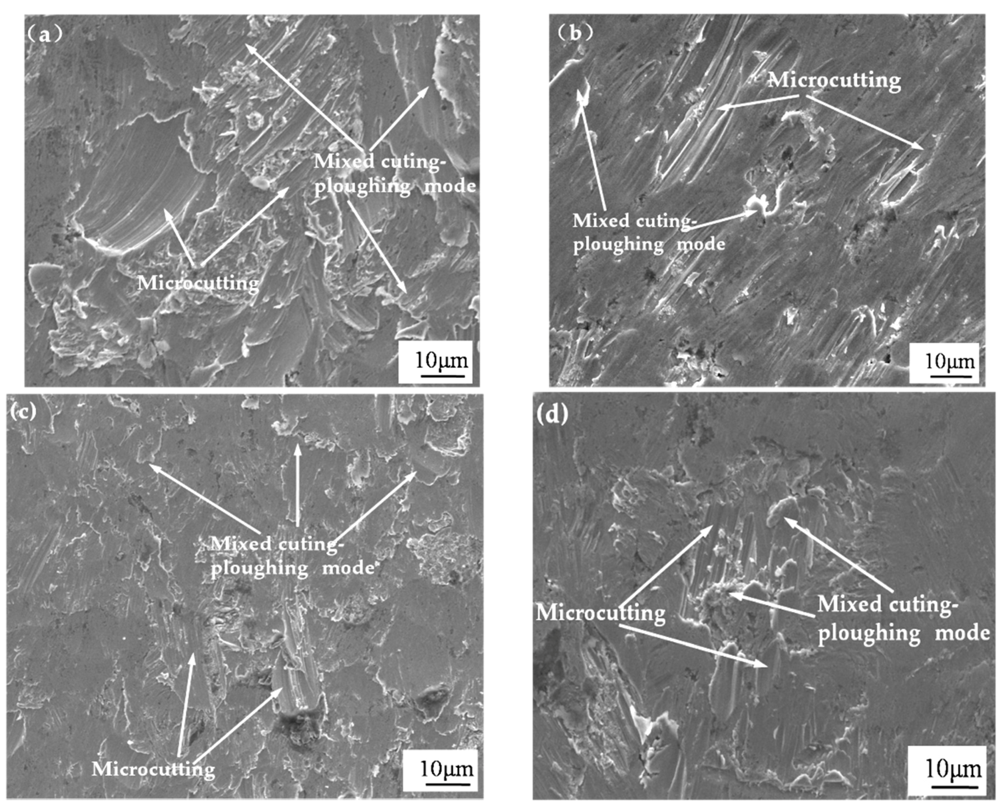
The SEM images showing the eroded surfaces of AlxCoCrFeNiTi0.5 HEA coatings are given in Figure 9 and Figure 10. Detailed examination of the images indicates that microcuting and mixed cutting and ploughing by irregularly shaped erodent particles are responsible for the material removal at 45° impingement angle. Grewal et al. [35] have proposed that with the impact of irregular particles, the primary mode of material removal was a mixture of cutting and ploughing at low impingement angle. Microcutting and mixed cutting-ploughing marks can be seen in Figure 9. At low impingement angle, the normal component of the impact force is too small compared to the tangential one. Material’s hardness is a predominant role against these deformation mechanisms. Compared to the hardness of sand particle, which is about 1100 HV, the highest hardness of AlxCoCrFeNiTi0.5 HEA coatings is only 801.3 HV.
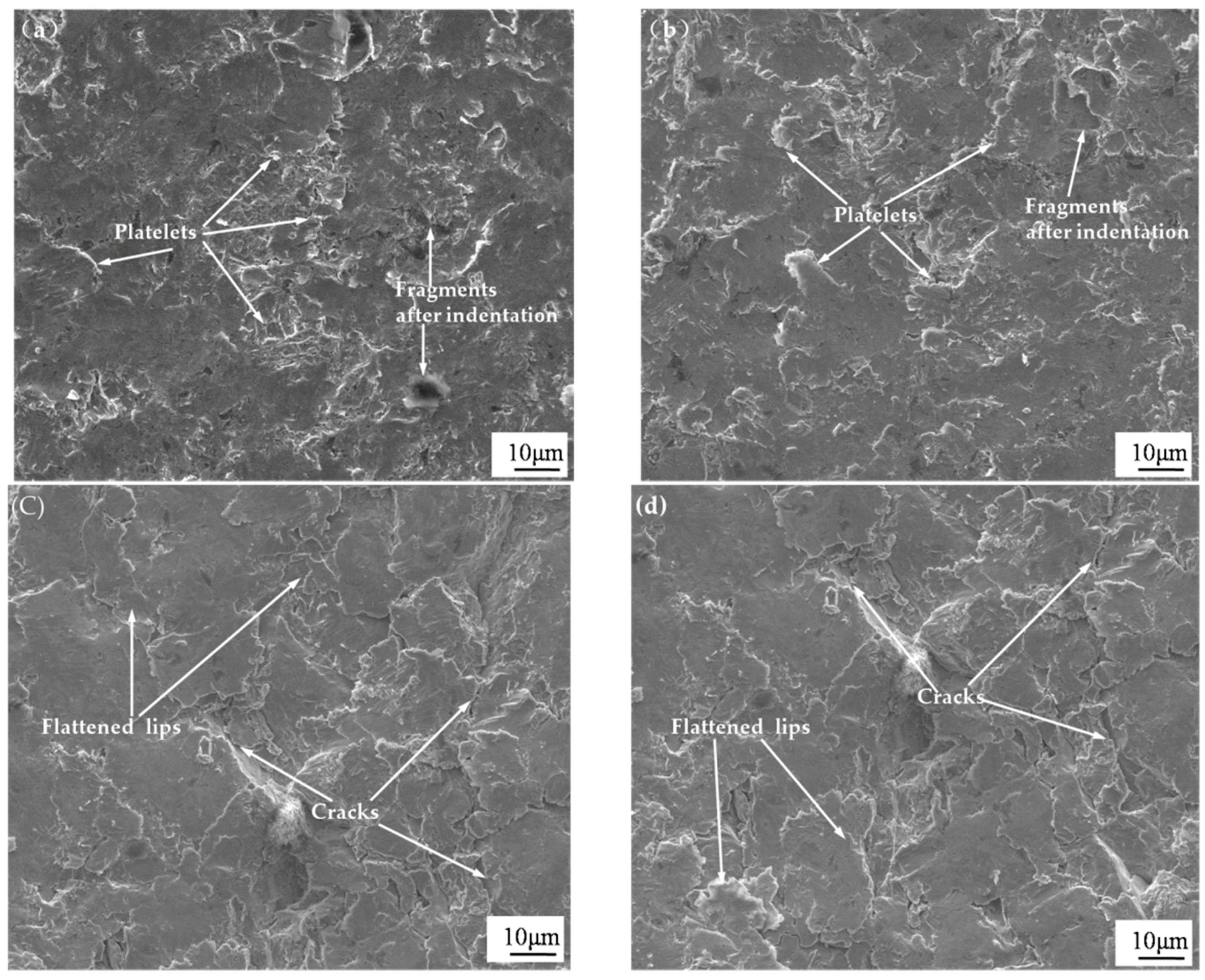
Figure 10a,b show the SEM images of eroded surfaces of Al1.0 and Al1.5HEA coatings. It can be observed that the eroded surfaces showed the presence of many deformed platelets and indentions. The formation of platelets was mainly through indention of impact sand particles. The material extruded from the craters tends to flow outward and accumulates around the periphery in form of platelets, which are removed by a number of subsequent normal impacts of the sand particles. The highly deformed surface of Al1.0 and Al1.5HEA coatings at 90° impingement indicates significant strain hardening. The major erosion mechanism for Al1.0 and Al1.5 HEA coatings is the formation and removal of material in the form of platelets at normal impingement angle. Figure 10c,d show the SEM micrographs of the eroded surface of Al2.0 and Al2.5 HEA coatings at 90° impingement angle. The presence of flattened lips indicates the limited ductility of coatings. Some cracks were also observed, which indicates that the coatings also were removed by brittle fracture. For brittle materials, the energy transfers as a result repeated particle impact results in a fatigue process at or close to normal incidence [36]. Due to high hardness and limited ductility, Al2.0 and Al2.5HEA coatings were undergone a rapid embrittlement during the continuous impact of erodent particles and fractured easily. In the case, erosion of Al2.0 and Al2.5 HEA coatings at 90° impingement is carried out by repetitive plastic deformation and brittle fracture. These observations of eroded surfaces appear to be back up the trend in erosion rates as discussed in Figure 6.
4. Conclusions
The phase composition and microstructure of as-laser cladding AlxCoCrFeNiTi0.5 HEA coatings have been studied. The effect of impingement angle, sand concentration and erosion time on the erosion behavior and mechanism of AlxCoCrFeNiTi0.5 HEA coatings were investigated by slurry erosion test. The following conclusions could be made.
- (1)
- AlxCoCrFeNiTi0.5 HEA coatings with few pores and the good metallurgical combination could be fabricated on Q345 substrate by laser cladding with the optimized processing parameters.
- (2)
- The crystal structures of AlxCoCrFeNiTi0.5 HEA coatings evolve from FCC plus BCC mixture phases for x = 1.0 to single BCC phase for x = 1.5, and then to BCC and IM mixture phases for x = 2.0 and 2.5. The microhardness of AlxCoCrFeNiTi0.5 HEA coatings increased obviously with the addition of Al element content. The Al2.5 HEA coating has the highest hardness of 801.1 HV.
- (3)
- AlCoCrFeNiTi0.5 HEA coating exhibits the ductile erosion mode under slurry erosion, a mixed erosion mode (neither ductile nor brittle) for Al1.5CoCrFeNiTi0.5HEA coating, whereas the Al2.0CoCrFeNiTi0.5 and Al2.5CoCrFeNiTi0.5HEA coatings exhibit the brittle erosion mode. AlCoCrFeNiTi0.5 HEA coating showed good slurry erosion resistance at all the investigated impingement angles due to its high hardness, good plasticity, and low stacking fault energy. The erosion rate of Al1.0 HEA coating is 1.78 times lower than Cr16 alloy at 45° impingement angle and 1.68 times lower at 90° impingement angle. The erosion rates of the test materials increase nonlinearly with the increase in the sand concentration at 45° and 90° impingement angles. The erosion time has no effect on the wear mechanism noticeably.
- (4)
- SEM observation confirms the dominant erosion mechanism for all HEA coatings was microcuting and mixed cutting and ploughing at low impingement angle. Platelets were observed to be the primary erosion mechanism for Al1.0 and Al1.5 HEA coatings at normal impingement angle, compared to repetitive plastic deformation and fatigue fracture being the prevailing material removal phenomenon for Al2.0 and Al2.5 HEA coatings.
Acknowledgments
The authors thankfully acknowledge to the financial support provided by the National Natural Science Foundation of China (No. 51475140), and the National Natural Science Foundation of China (No. 51774109).
Author Contributions
Aibin Ma and Xiulin Ji conceived and designed the experiments; Jianhua Zhao and Yayun Bao performed the experiments; Jinhua Jiang supervised experimental work and data analysis; Jianhua Zhao wrote the paper.
Conflicts of Interest
The authors declare no conflict of interest.
References
- Manisekaran, T.; Kamaraj, M.; Sharrif, S.M.; Joshi, S.V. Slurry erosion studies on surface modified 13Cr-4Ni steels: Effect of angle of impingement and particle size. J. Mater. Eng. Perform. 2007, 16, 567–572. [Google Scholar] [CrossRef]
- Nguyen, Q.B.; Lim, C.Y.H.; Nguyen, V.B.; Wan, Y.M.; Nai, B.; Zhang, Y.W.; Gupta, M. Slurry erosion characteristics and erosion mechanisms of stainless steel. Tribol. Int. 2014, 79, 1–7. [Google Scholar] [CrossRef]
- Varalakshmi, S.; Rao, G.A.; Kamaraj, M.; Murty, B.S. Hot consolidation and mechanical properties of nanocrystalline equiatomic AlFeTiCrZnCu high entropy alloy after mechanical alloying. J. Mater. Sci. 2010, 45, 5158–5163. [Google Scholar] [CrossRef]
- Wu, Z.; Bei, H.; Pharr, G.M.; George, E.P. Temperature dependence of the mechanical properties of equiatomic solid solution alloys with face-centered cubic crystal structures. Acta Mater. 2014, 81, 428–441. [Google Scholar] [CrossRef]
- Soare, V.; Mitrica, D.; Constantin, I.; Badilita, V.; Stoiciu, F.; Popescu, A.-M.J.; Carcea, I. Influence of remelting on microstructure, hardness and corrosion behaviour of AlCoCrFeNiTi high entropy alloy. Mater. Sci. Technol. 2015, 31, 1194–1200. [Google Scholar] [CrossRef]
- Shi, Y.Z.; Yang, B.; Liaw, P.K. Corrosion-resistance high-entropy alloys: A review. Metals 2017, 7, 43. [Google Scholar] [CrossRef]
- Chuang, M.H.; Tsai, M.H.; Wang, W.R.; Lin, S.J.; Yeh, J.W. Microstructure and wear behavior of AlxCo1.5CrFeNi1.5Tiy high-entropy alloys. Acta Mater. 2011, 59, 6308–6317. [Google Scholar] [CrossRef]
- Senkov, O.N.; Wilks, G.B.; Miracle, D.B.; Chuang, C.P.; Liaw, P.K. Refractory high-entropy alloys. Intermetallics 2010, 18, 1758–1765. [Google Scholar] [CrossRef]
- Ocelik, V.; Janssen, N.; Smith, S.N.; De Hosson, J.T.M. Additive manufacturing of high-entropy alloys by laser processing. JOM 2016, 68, 1810–1818. [Google Scholar] [CrossRef]
- Huang, C.; Zhang, Y.Z.; Vilar, R.; Shen, J.Y. Dry sliding wear behavior of laser clad TiVCrAlSi high entropy alloy coatings on Ti-6A1-4V substrate. Mater. Des. 2012, 41, 338–343. [Google Scholar] [CrossRef]
- Yue, T.M.; Xie, H.; Lin, X.; Yang, H.O.; Meng, G.H. Solidification behaviour in laser cladding of AlCoCrCuFeNi high-entropy alloy on magnesium substrates. J. Alloys Compd. 2014, 587, 588–593. [Google Scholar] [CrossRef]
- Kunce, I.; Polansk, M.; Karczewski, K.; Plocinski, T.; Kurzydlowski, K.J. Microstructural characterisation of high-entropy alloy AlCoCrFeNi fabricated by laser engineered net shaping. J. Alloys Compd. 2015, 648, 751–758. [Google Scholar] [CrossRef]
- Zhou, Y.J.; Zhang, Y.; Kim, T.N.; Chen, G.L. Microstructure characterizations and strengthening mechanism of multi-principal component AlCoCrFeNiTi0.5 solid solution alloy with excellent mechanical properties. Mater. Lett. 2008, 62, 2673–2676. [Google Scholar] [CrossRef]
- Jiao, Z.M.; Ma, S.G.; Chu, M.Y.; Yang, H.J.; Wang, Z.H.; Zhang, Y.; Qiao, J.W. Superior mechanical properties of AlCoCrFeNiTix high-entropy alloys upon dynamic loading. J. Mater. Eng. Perform. 2015, 25, 451–456. [Google Scholar] [CrossRef]
- Guo, S.; Liu, C.T. Phase stability in high entropy alloys: Formation of solid-solution phase or amorphous phase. Prog. Nat. Sci. Mater. Int. 2011, 21, 433–446. [Google Scholar] [CrossRef]
- Tang, Z.; Gao, M.C.; Diao, H.Y.; Yang, T.F.; Liu, J.P.; Zuo, T.T.; Zhang, Y.; Lu, Z.P.; Cheng, Y.Q.; Zhang, Y.W.; et al. Aluminum alloying effects on lattice types, microstructures, and mechanical behavior of high-entropy alloys systems. JOM 2013, 65, 1848–1858. [Google Scholar] [CrossRef]
- Zhang, K.B.; Fu, Z.Y. Effects of annealing treatment on phase composition and microstructure of CoCrFeNiTiAlx high-entropy alloys. Intermetallics 2012, 22, 24–32. [Google Scholar] [CrossRef]
- Tong, C.J.; Chen, M.R.; Chen, S.K.; Yeh, Y.W.; Shun, T.T.; Lin, S.J.; Chang, S.Y. Mechanical performance of the AlxCoCrCuFeNi high-Entropy alloy system with multiprincipal elements. Metall. Mater. Trans. A 2005, 36, 263–1271. [Google Scholar]
- Wang, Y.F.; Yang, Z.G. Finite element model of erosive wear on ductile and brittle materials. Wear 2008, 265, 871–878. [Google Scholar] [CrossRef]
- Okonkwo, P.C.; Shakoor, R.A.; Zagho, M.M.; Mohamed, A.M.A. Erosion behavior of API X100 pipeline steel at various impact angles and particle speeds. Metals 2016, 6, 232. [Google Scholar] [CrossRef]
- Wen, D.C. Erosion and wear behavior of nitrocarburized DC53 tool steel. Wear 2010, 268, 629–636. [Google Scholar] [CrossRef]
- Arora, H.S.; Grewal, H.S.; Singh, H.; Mukherjee, S. Zirconium based bulk metallic glass—Better resistance to slurry erosion compared to hydroturbine steel. Wear 2013, 307, 28–34. [Google Scholar] [CrossRef]
- Zhou, Y.J.; Zhang, Y.; Wang, Y.L.; Chen, G.L. Solid solution alloys of AlCoCrFeNiTix with excellent room-temperature mechanical properties. Appl. Phys. Lett. 2007, 90, 181904. [Google Scholar] [CrossRef]
- Nair, R.B.; Selvam, K.; Arora, H.S.; Mukherjee, S.; Singh, H.; Grewal, H.S. Slurry erosion behavior of high entropy alloys. Wear 2017, 386–387, 230–238. [Google Scholar] [CrossRef]
- Zaddach, A.J.; Niu, C.; Koch, C.C.; Irving, D.L. Mechanical properties and stacking fault energies of NiFeCrCoMn high-entropy alloy. JOM 2013, 65, 1780–1789. [Google Scholar] [CrossRef]
- Das, A. Revisiting stacking fault energy of steels. Metall. Mater. Trans. A 2016, 47, 748–768. [Google Scholar] [CrossRef]
- Zhao, J.; Zhang, G.C.; Xu, Y.J.; Wang, R.H.; Zhou, W.D.; Han, L.X.; Zhou, Y. Mechanism and effect of jet parameters on particle water jet rock breaking. Power Technol. 2017, 313, 231–244. [Google Scholar] [CrossRef]
- Burzynski, T.; Papini, M. Analytical models of the interference between incident and rebounding particles within an abrasive jet: Comparison with computer simulation. Wear 2007, 263, 1593–1601. [Google Scholar] [CrossRef]
- Ciampini, D.; Spelt, J.K.; Papini, M. Simulation of interference effects in particle streams following impact with a flat surface: Part II. Parametric study and implications for erosion testing and blast cleaning. Wear 2003, 254, 237–249. [Google Scholar] [CrossRef]
- Goyal, D.K.; Singh, H.; Kumar, H. An overview of slurry erosion control by the application of high velocity oxy fuel sprayed coatings. J. Eng. Tribol. 2011, 225, 1092–1105. [Google Scholar] [CrossRef]
- Padhy, M.K.; Saini, R.P. Effect of size and concentration of silt particles on erosion of Pelton turbine buckets. Energy 2009, 34, 1477–1483. [Google Scholar] [CrossRef]
- Grewal, H.S.; Arora, H.S.; Agrawa, A.; Singha, H.; Mukherjee, S. Slurry erosion of thermal spray coatings: Effect of sand concentration. Procedia Eng. 2013, 68, 484–490. [Google Scholar] [CrossRef]
- Singh, H.; Goyal, K.; Goyal, D.K. Experimental investigations on slurry erosion behaviorof HVOF and HVOLF sprayed coatings on hydraulic turbine steel. Trans. Indian Inst. Met. 2017, 70, 1585–1592. [Google Scholar] [CrossRef]
- Goyal, D.K.; Singh, H.; Kumar, H.; Sahni, V. Slurry erosion behavior of HVOF sprayed WC-10Co-4Cr and Al2O3 + 13TiO2 coatings on a turbine steel. Wear 2012, 289, 46–57. [Google Scholar] [CrossRef]
- Grewal, H.S.; Agrawal, A.; Singh, H. Slurry erosion mechanism of hydroturbine steel: Effect of operating parameters. Tribol. Lett. 2013, 52, 287–303. [Google Scholar] [CrossRef]
- Wheeler, D.W.; Wood, R.J.K. Erosion of hard surface coatings for use in offshore gate valves. Wear 2005, 258, 526–536. [Google Scholar] [CrossRef]
Figure 1.
Schematic view of the slurry erosion test rig.

Figure 2.
Micro-morphologies of the AlCoCrFeNiTi0.5 HEA (High-entropy alloy) coating for (a) surface and (b) cross-section single-track coating.
Figure 2.
Micro-morphologies of the AlCoCrFeNiTi0.5 HEA (High-entropy alloy) coating for (a) surface and (b) cross-section single-track coating.

Figure 3.
X-ray diffraction patterns of AlxCoCrFeNiTi0.5 HEA coatings.

Figure 4.
Vickers hardness of AlxCoCrFeNiTi0.5 HEA coatings with different aluminum contents.
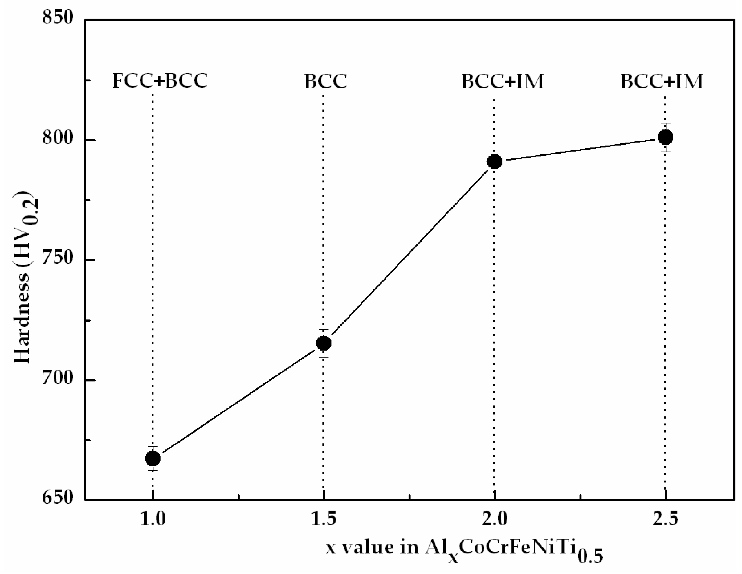
Figure 5.
SEM (scanning electron microscopy) images of the as-laser cladding AlxCoCrFeNiTi0.5 HEA coatings: (a) Al1.0; (b) Al1.5; (c) Al2.0; and (d) Al2.5.
Figure 5.
SEM (scanning electron microscopy) images of the as-laser cladding AlxCoCrFeNiTi0.5 HEA coatings: (a) Al1.0; (b) Al1.5; (c) Al2.0; and (d) Al2.5.
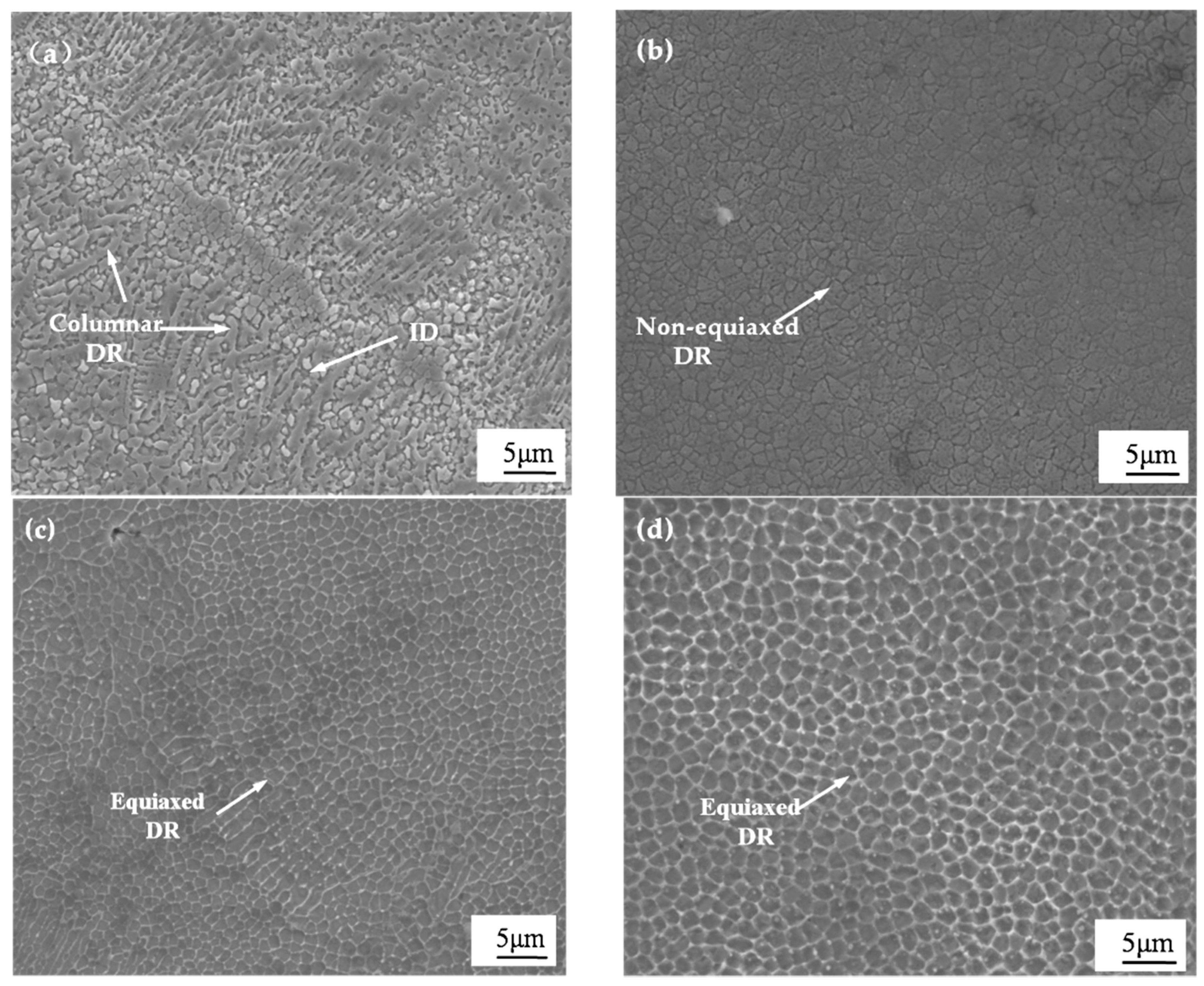
Figure 6.
Variation in erosion rate of AlxCoCrFeNiTi0.5 HEA coatings and Cr16 alloy with impact angle at a velocity of 10.08 m/s.
Figure 6.
Variation in erosion rate of AlxCoCrFeNiTi0.5 HEA coatings and Cr16 alloy with impact angle at a velocity of 10.08 m/s.

Figure 7.
Variation in erosion rate of AlxCoCrFeNiTi0.5 HEA coatings and Cr16 alloy with sand concentration at a velocity of 10.08 m/s and impingement angle of (a) 45° and (b) 90°.
Figure 7.
Variation in erosion rate of AlxCoCrFeNiTi0.5 HEA coatings and Cr16 alloy with sand concentration at a velocity of 10.08 m/s and impingement angle of (a) 45° and (b) 90°.
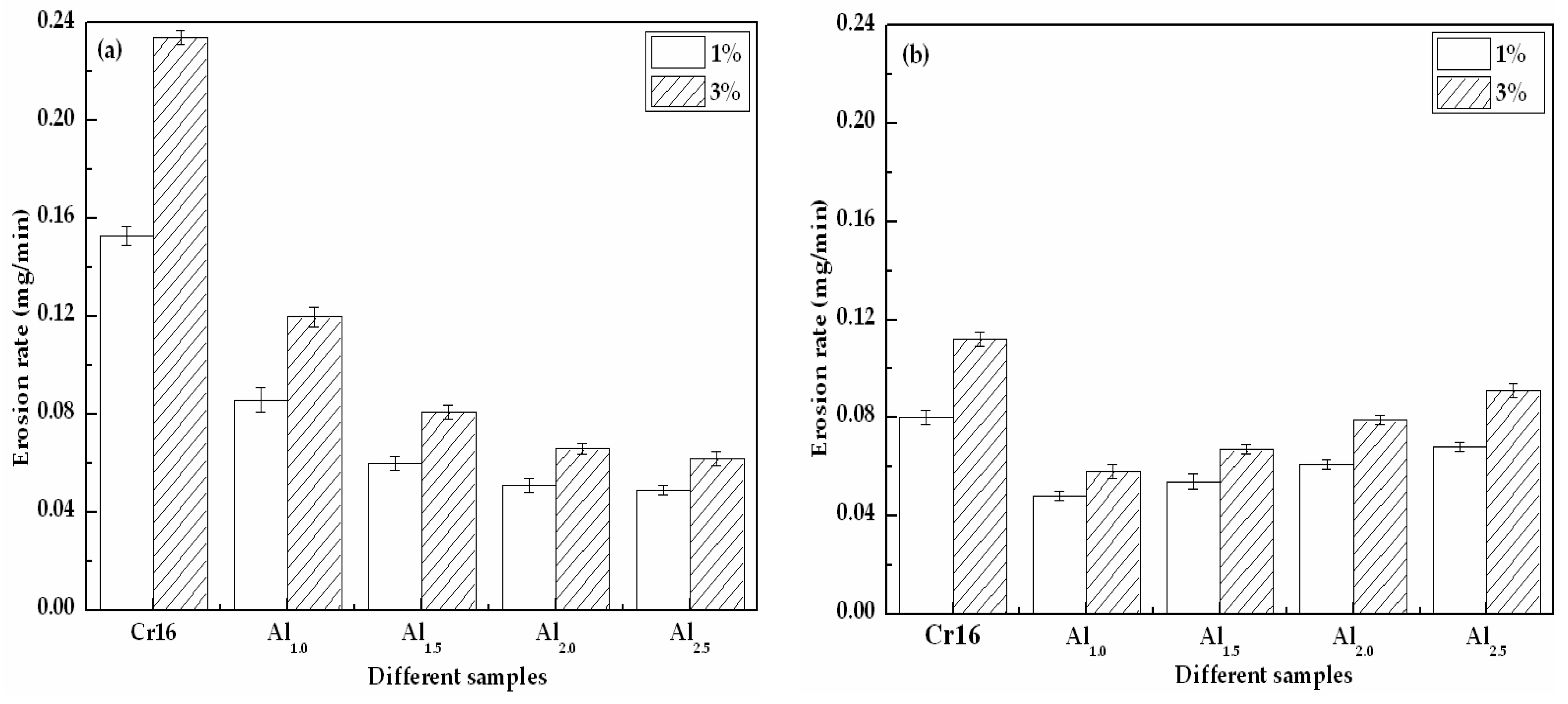
Figure 8.
Variation in erosion rate of AlxCoCrFeNiTi0.5 HEA coatings and Cr16 alloy with erosion time at a velocity of 10.08 m/s and impingement angle of (a) 45° and (b) 90°.
Figure 8.
Variation in erosion rate of AlxCoCrFeNiTi0.5 HEA coatings and Cr16 alloy with erosion time at a velocity of 10.08 m/s and impingement angle of (a) 45° and (b) 90°.
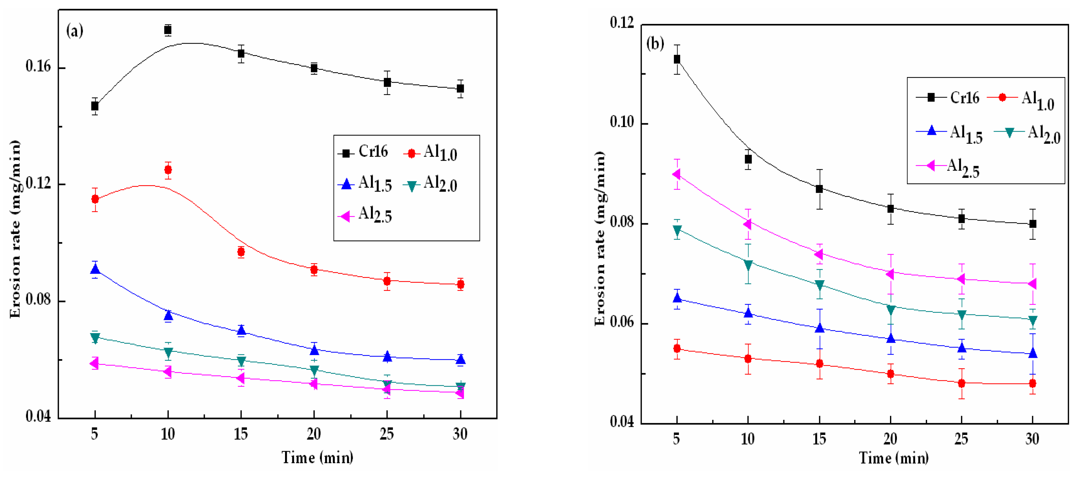
Figure 9.
The eroded surface SEM micrographs of AlxCoCrFeNiTi0.5 HEA coatings after 30-min slurry erosion: (a) Al1.0; (b) Al1.5; (c) Al2.0; and (d) Al2.5 at 10.08 m/s, 1.0 wt. % sand concentration and 45° impingement angle.
Figure 9.
The eroded surface SEM micrographs of AlxCoCrFeNiTi0.5 HEA coatings after 30-min slurry erosion: (a) Al1.0; (b) Al1.5; (c) Al2.0; and (d) Al2.5 at 10.08 m/s, 1.0 wt. % sand concentration and 45° impingement angle.

Figure 10.
The eroded surface SEM micrographs of AlxCoCrFeNiTi0.5 HEA coatings after 30-min slurry erosion: (a) Al1.0; (b) Al1.5; (c) Al2.0; and (d) Al2.5 at 10.08 m/s, 1.0 wt. % sand concentration and 90° impingement angle.
Figure 10.
The eroded surface SEM micrographs of AlxCoCrFeNiTi0.5 HEA coatings after 30-min slurry erosion: (a) Al1.0; (b) Al1.5; (c) Al2.0; and (d) Al2.5 at 10.08 m/s, 1.0 wt. % sand concentration and 90° impingement angle.

Table 1.
Parameters employed for slurry erosion testing.
| Parameters (Unit) | Quantitative Value |
|---|---|
| Impinged angle (°) | 15, 30, 45, 60, 90 |
| Impinged velocity (m/s) | 10.08 |
| Impinged medium | Tap water mixed with fresh river sand |
| Nozzle diameter (mm) | 8 |
| Erosion time (min) | 30 |
© 2018 by the authors. Licensee MDPI, Basel, Switzerland. This article is an open access article distributed under the terms and conditions of the Creative Commons Attribution (CC BY) license (http://creativecommons.org/licenses/by/4.0/).
Share and Cite
MDPI and ACS Style
Zhao, J.; Ma, A.; Ji, X.; Jiang, J.; Bao, Y. Slurry Erosion Behavior of AlxCoCrFeNiTi0.5 High-Entropy Alloy Coatings Fabricated by Laser Cladding. Metals 2018, 8, 126. https://doi.org/10.3390/met8020126
AMA Style
Zhao J, Ma A, Ji X, Jiang J, Bao Y. Slurry Erosion Behavior of AlxCoCrFeNiTi0.5 High-Entropy Alloy Coatings Fabricated by Laser Cladding. Metals. 2018; 8(2):126. https://doi.org/10.3390/met8020126
Chicago/Turabian StyleZhao, Jianhua, Aibin Ma, Xiulin Ji, Jinghua Jiang, and Yayun Bao. 2018. "Slurry Erosion Behavior of AlxCoCrFeNiTi0.5 High-Entropy Alloy Coatings Fabricated by Laser Cladding" Metals 8, no. 2: 126. https://doi.org/10.3390/met8020126
Note that from the first issue of 2016, this journal uses article numbers instead of page numbers. See further details here.