Mechanical Properties of Stainless-Steel Structures Fabricated by Composite Extrusion Modelling


Fluid Technology and Microfluidics, University of Rostock, Justus-von-Liebig Weg 6, 18059 Rostock, Germany
*
Author to whom correspondence should be addressed.
Metals 2018, 8(2), 84; https://doi.org/10.3390/met8020084
Submission received: 22 December 2017
/
Revised: 17 January 2018
/
Accepted: 19 January 2018
/
Published: 24 January 2018
(This article belongs to the Special Issue Metallic Additive Manufacturing: Design, Process and Post-processing)
Abstract
:Composite Extrusion Modelling (CEM) is a new additive manufacturing process for metal that uses Metal Injection Moulding (MIM) materials. The MIM material is printed on a build plate using a moveable extruder. Subsequently, the printed greenparts are debinded and sintered in a two-step oven process. In contrast to beam-based additive processes, the microstructure of the part is not generated layer-wise by melting and solidifying small areas, but in a steady manner during sintering from the outside of the part to the inside, in order to create dense metal parts. In this study, various structures were printed and sintered in order to investigate the mechanical properties and dimensional properties of the resulting stainless-steel structures, and their dependence on the infill percentage. The measured density of the dense sintered parts is 7.47 g/cm3 and the sintering shrinkage is in the range from 14.6 to 16.8%. The compressive strength (σdm50) of the specimens varies in the range from 1220 to 2345 MPa dependent on the infill percentage. The measured density and the sintering shrinkage are very close to the values specified by the manufacturer of the MIM material.
1. Introduction
Additive manufacturing (AM) technologies are gaining importance in industrial fields of application. The reasons for this include optimized processes, new materials and upcoming new technologies that match the requirements of modern industry. After decades of prototyping, some of the technologies are now in operative use for direct manufacturing of customized parts or small batch series production [1]. In particular, the additive manufacturing of metal parts using beam-based processes, such as selective electron beam or selective laser melting (SEBM/SLM), has significant potential to become part of future production complexes [2,3,4]. The increasing importance of AM technologies is demonstrated by the steady increase of the market and the corresponding machine sales. In 2016, the market for additive manufacturing grew 17.4% (CAGR) to a value of $6.063 billion [5].
A new metal AM technology developed at the University of Rostock is called Composite Extrusion Modelling (CEM). The CEM process is a two-step additive manufacturing process, based on two different technologies. One is the fused filament fabrication (FFF) process, which liquefies a thermoplastic wire in a heated extruder. Relative movements between extruder and build plate lead to the extruded filament building up the single layers of a three-dimensional object. This technology was initially presented by the company Stratasys Ltd. (Eden Prairie, MN, USA) [6]. It is limited to thermoplastic materials that are flexible enough to spool as a wire, which means that only thermoplastic polymers or thermoplastic polymers with a relatively small amount of additives, such as metal or ceramic, could be printed. These additives can change the look and the mechanical properties of the printed part but are not present in quantities high enough to build dense metal parts. The second technology is Metal Injection Moulding (MIM), which belongs to the field of powder metallurgy. It combines the advantages of injection moulding, such as high cost efficiency, reproducibility and a good design freedom, with the advantages of powder metallurgy, for example, the use of high-strength materials. The MIM process has four different steps. The first is the manufacturing of the raw material, known as “feedstock”. The feedstock is produced by mixing up to 50 vol. % metal powder particles and thermoplastic granules in a twin-screw extruder [7]. By extruding and cutting this blend, a granule is formed. In the next step an injection moulding process takes place. The feedstock is liquefied and injected into moulds by a three-zone screw extruder. In this manner, greenparts are formed. In the third process step, these greenparts are debinded. This means a part of the thermoplastic binder is dissolved chemically and or thermally. Subsequently these brown parts are sintered in a sintering oven under an inert gas atmosphere, which is the fourth step.
The CEM process combines these two basis technologies by using the FFF technology to replace the injection moulding within the MIM process in order to form the greenparts. The unique feature of the process is that conventional MIM granules are processed directly in a specially developed small-sized screw extruder. An overview of the CEM process is shown in Figure 1.
Eliminating the injection moulding process removes the need for moulds, which means parts can be produced in a quantity of one. To print a new part a three-dimensional surface model is necessary. This part may have the file format STL (Standard Tessellation Language) and can be exported from computer-aided design (CAD) software, 3D-scanning software or other 3D modellers. To print a model, the STL file has to be virtually cut into slices of the desired layer height. Simultaneously for each layer, tool paths are calculated that contain information about the contour and infill of the part. This tool path is called G-Code and contains the information for the printer regarding the movement of the axes and extrusion of the material.
Past studies presented the possibility of printing and sintering greenparts, as well as preliminary results on mechanical strength [8,9]. Properties such as absolute dimensional accuracy were not investigated, because these values are not process-relevant but rather depend on the accuracy of the used machine and their linear actors, which are not the focus of this study. The aim of this study is to show the potential of the CEM process for technical applications. Therefore, various process-relevant geometrical and mechanical properties are investigated.
2. Materials and Methods
2.1. 3D Printing Device
The device for printing with the CEM-process consists of a moveable extruder and an X, Y, Z kinematic controlled by drive electronics. The extruder consists of three zones, a feed zone, a heated liquefying zone and a heated extrusion zone [10]. The extruder is built up vertically and possesses a hopper that is attached to the feed zone and filled with the desired granules. Due to its small size of approximately 60 mm × 60 mm × 120 mm and its weight of 2 kg, the extruder can be moved on a linear kinematic. The setup that was used for the tests in this study used timing belt axis for X and Y movement of the extruder and screw drive axis for the movement of the build plate. The printer has a build volume of 150 mm × 150 mm × 150 mm (X, Y, Z). The axes are driven by NEMA 23 stepper motors (Nanotec Electronic GmbH & Co. KG, Feldkirchen, Germany) and controlled with an Arduino-based microcontroller called Minitronics by RepRapWorld B.V. (Nootdorp, The Netherlands) and open-source firmware called Marlin by Scott Lahteine. The software that was used to generate the G-Code and control the print process is Simplify3D (Simplify3d LLC, Blue Ash, OH, USA).
2.2. Test Structures
To demonstrate the feasibility of additive manufacturing with common MIM granules, and to test the resulting strength of the sintered parts, bars and cylinders were designed. The bars are used to determine the geometrical properties of the printed parts as well as investigate the shrinkage. The cylinders are used for geometrical investigations and compression strength tests. The bars have a length of 120 mm, a width of 10 mm and a height of 5 mm and were printed lying flat on the build platform. The cylinders have a height of 20 mm and a diameter of 10 mm and were printed upright on the build platform. To compensate the expected shrinkage these dimensions are multiplied by 1.15 according to the oversizing factor that is given by the manufacturer of the MIM material. This means the bars were printed with 138 mm length, 11.5 mm width and 5.75 mm height and the cylinders have a diameter of 11.5 mm and a height of 23 mm. The printing parameters for the bars and the cylinders are displayed in Table 1.
The bars were printed solid; the cylinders were printed with increasing infill percentage from 0% (hollow) to 100% (solid) in 20% steps. The chosen infill pattern was a rectilinear grid.
2.3. Material
For this study, the conventional MIM feedstock Catamold® 17-4PH F from BASF SE was used. The feedstock is a blend of the metallic alloy X5CrNiCuNb17-4 certified according to standard EN/DIN 1.4542 and polyoxymethylene (POM) as thermoplastic binder. Table 2 gives an overview of the technical data provided by the manufacturer (BASF SE. Carbonyl Iron Powder & Metal Systems. Product Specification, CAM-CAT_17-4PHF-E Revision 2, October 2008).
This information provided by BASF SE refers to the process information for the metal injection moulding standard process. A higher temperature than 200 °C is to be avoided because of the risk of dissolving formaldehyde. It has to be noted that the used extruder temperature of 215 °C in Table 1 refers to the measured temperature at the heater cartridges. The temperature loss through the wall of the extruder is approximately 15 to 20 °C. A dissolving of formaldehyde could not be recognized.
2.4. Debinding and Sintering
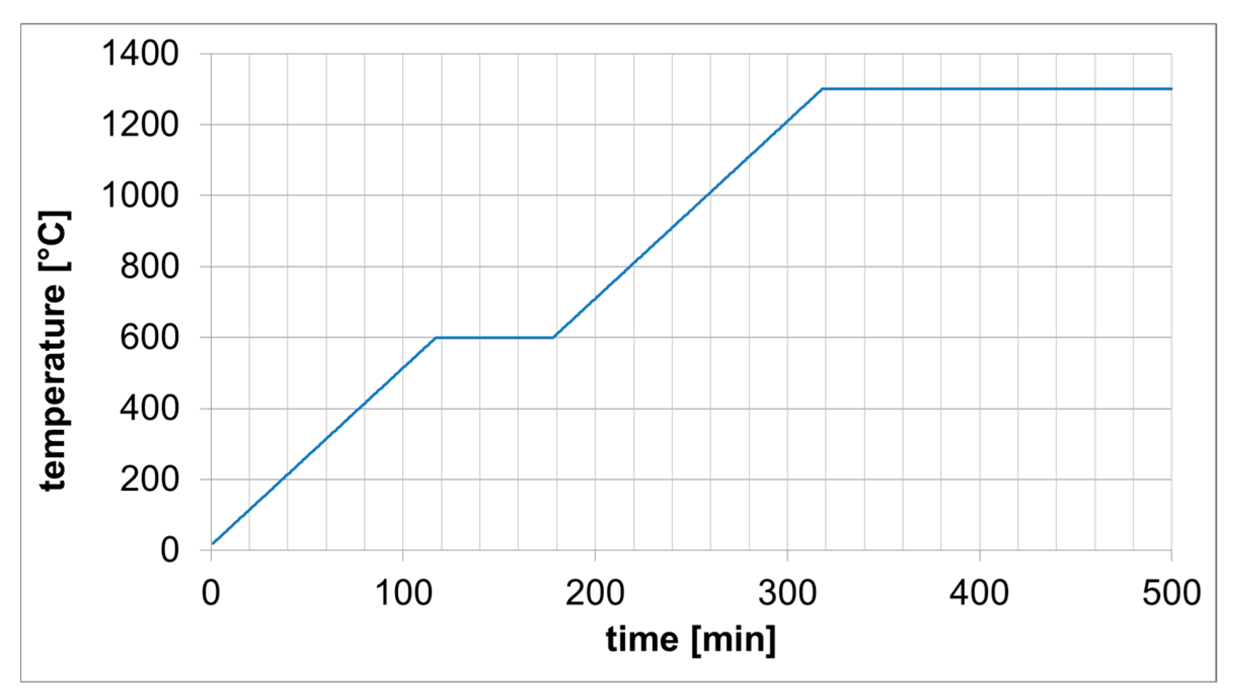
The debinding and sintering processes of the greenparts were carried out by ITB Precisietechniek (Boxtel, The Netherlands). The process was executed according to the standard sintering cycle for Catamold® 17-4PH F provided by BASF (Processing Instructions, VH/CA 046e, Ludwigshafen, Germany, February 2008). During the debinding process, POM is catalytically dissolved at 110 °C using HNO3 > 98%. The nitric acid has a throughput of 30 mL/h and is mixed with a feed of 500 mL/h purging gas (nitrogen) based on a 50 L oven. After a loss of 7.24 wt. %, the debinding process is finished, and the brown parts are subsequently put into the sintering oven. The sintering cycle is shown in Figure 2.
During the first hours of sintering, the remaining binder is pyrolysed and removed by ventilation. After that, the metal parts fuse together and the metallic microstructure forms from the outside of the part to the inside. The parts were sintered at the same orientation as they were printed, the bars lying flat and the cylinders standing upright.
2.5. Analysis
The geometrical measurements were accomplished with a tactile digital calliper (resolution 0.01 mm, accuracy ± 0.02 mm) and a confocal laser scanning microscope (CLSM) LEXT OLS 4000 (Olympus, Tokyo, Japan). Five bars and five cylinders for each infill gradient were analysed. The dimensions were determined by averaging of at least five measured values.
The mass was measured with a SBC31 precision scale (Scaltec Instruments GmbH, Heiligenstadt, Germany). The density was calculated from the mass and the volume of the printed greenparts and sintered specimens. Additionally, the sintered cylinders were turned for precise density investigations.
The mechanical characterizations were made using a uniaxial testing machine Zwick/Roell Z400 (Zwick GmbH & Co. Kg, Ulm, Germany) with a maximum load of 400 kN. The compression strength was determined according to DIN 50106 with cylindrical samples. The compressive strengths were determined for a given strain of 40% (σdm40) and 50% (σdm50). To increase the quality of the measurement the top and bottom surfaces of the cylinders were faced. The load was applied by two parallel plates, one rigid the other as compression stamp.
The plates were coated with silicon oil (WD40) and the probes were placed on the rigid plate. Multiplication of the required standard compression speed (0.0062 s−1) with the sample height (20 mm) results in the necessary test speed of 0.134 mm/s.
3. Results
3.1. Results of Geometrical Investigations and Mass Measurement
The dimensions of the 3D-printed greenparts parts were measured, the parts were marked with engravings on the bottom surface and sent to ITB Precisietechniek for debinding and sintering. After this, the dimensions of the sintered parts were measured again. The new measured values reveal the sintering shrinkage. Absolute dimensions and shrinkage are shown in Table 3 and Table 4, below.
Because of the high surface roughness after printing (Figure 3a), the cylinders were also turned (Figure 3b) for further investigation of the density.
The averaged measurements of the turned cylinders are shown in Table 5.
3.2. Results of Mechanical Investigations
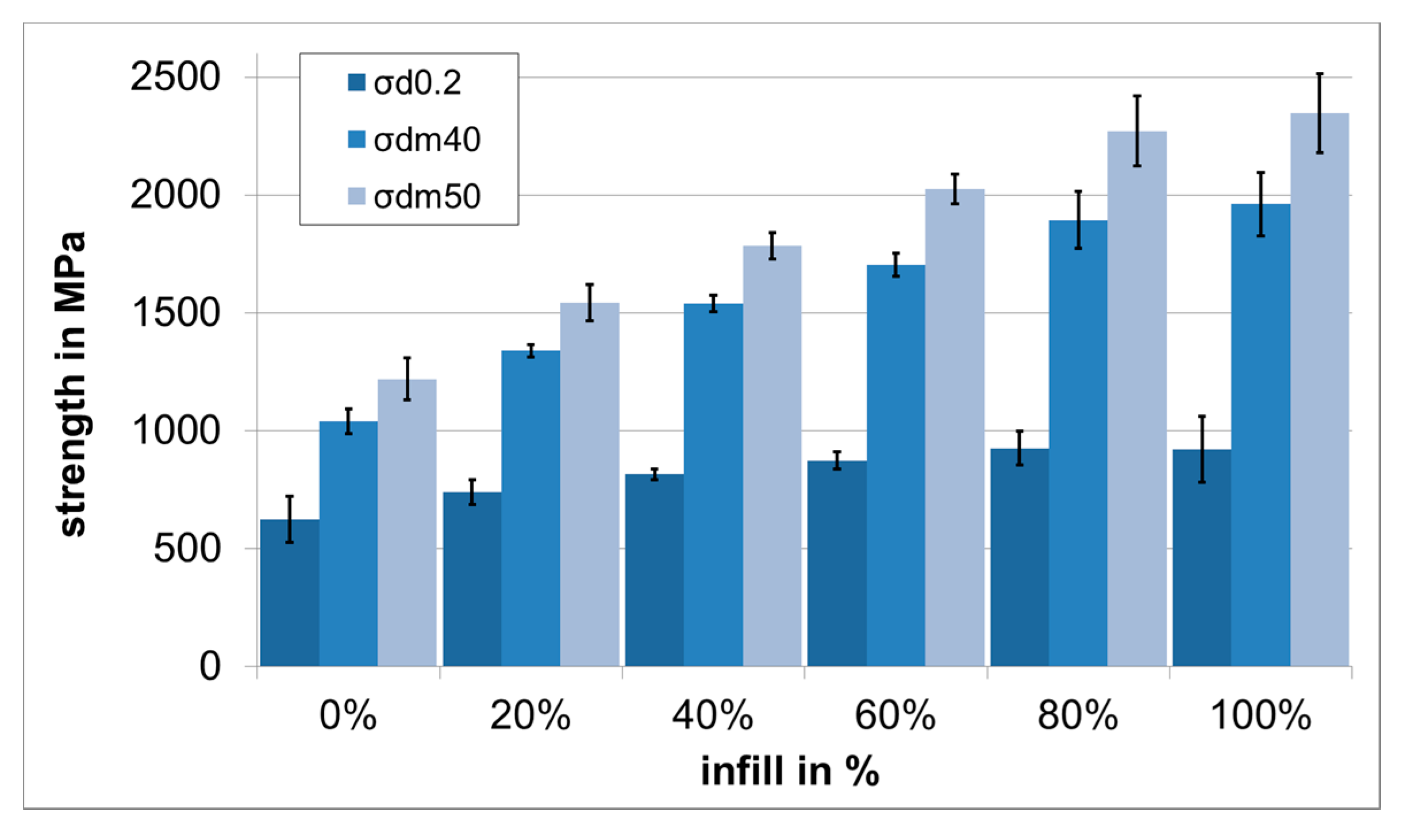
The compression strength tests showed average compression strength of 2345 MPa (σdm50) and a compressive yield strength σd0.2 of 922 MPa for specimens with an infill of 100%. For better comparison with the results from past studies, the compression strength for 40% compression σdm40 was also specified with 1961 MPa. The compression strength for all specimens with infills from 0% to 100% are shown in Table 6 and Figure 4.
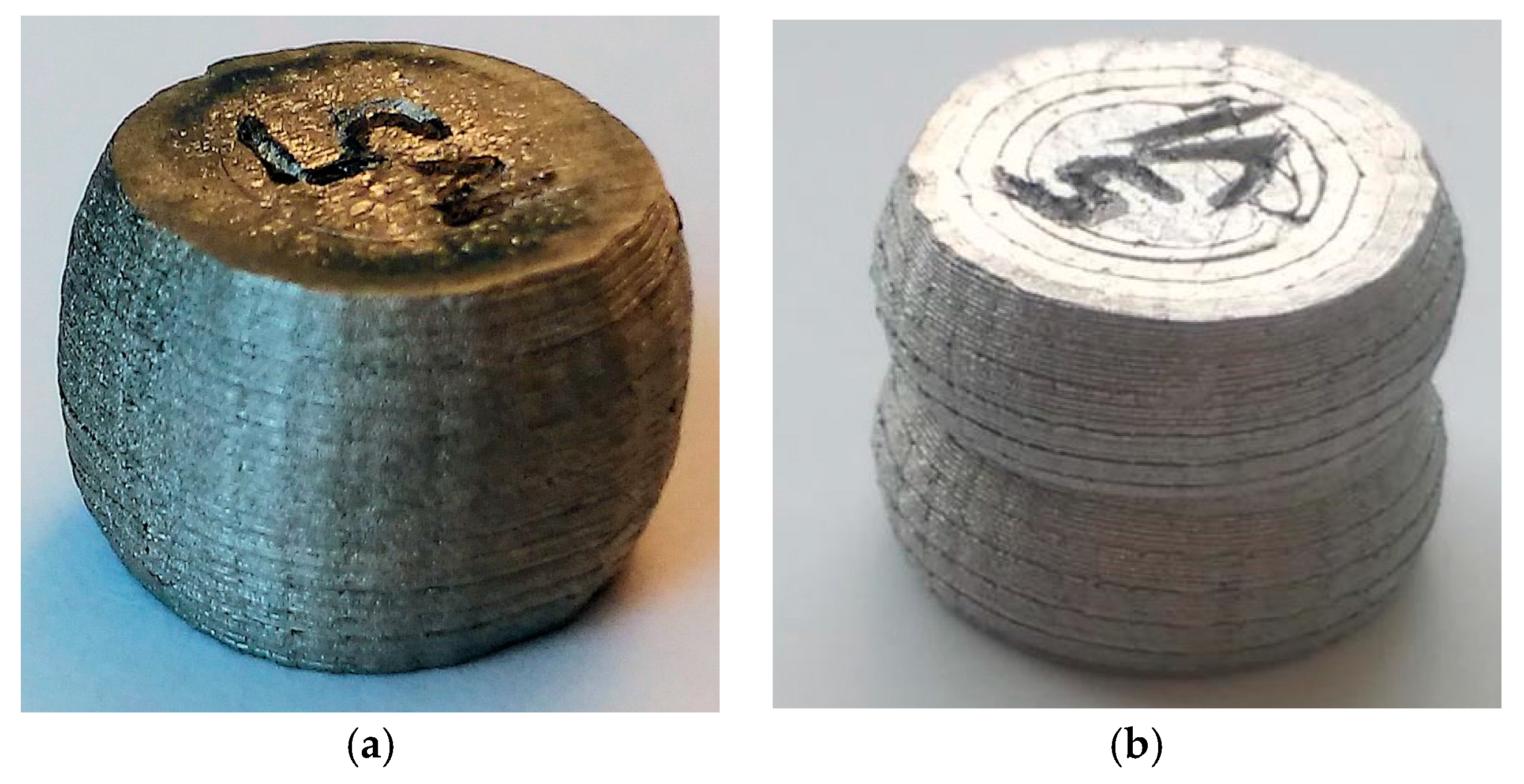
The impact to the deformation behaviour is clearly visible in Figure 5. The dense specimen shows a characteristic barrel shape after compression, whereas the hollow specimen shows the typical buckling behaviour of a hollow cylinder.
4. Discussion
The results of the geometrical investigations of the bars and the cylinders show that the sintering shrinkage in the X and Y build directions (length, width and height) is between 14.6 and 16.8 and comes very close to the specifications given by the material manufacturer. The shrinkage in the Z build direction is slightly higher, at 1.19 and 1.20. These results correspond to the results of past studies [8,9]. It is assumed that the shrinkage in Z is slightly higher because of the orientation in the oven during the sintering process. However, when printing with MIM materials the standard values for shrinkage that are given by the manufacturer cannot be adopted directly. The absolute dimensions of the greenpart indicate that there is a difference between target dimension and actual dimension of the printed parts. This is caused by the resolution of the printers’ axes, and is not investigated in this study.
The mechanical properties show better results than in past studies. For solid cylinders, there is a strength of 1961 MPa at compressive strain of 40%, compared to a strength of 1288 MPa in past studies [8]. The higher strength is caused by a more constant extrusion process that leads to parts with a higher density. The density of the turned cylinder (7.47 g/cm3) is close to the typical value for the density of 7.67 g/cm3 given by the materials manufacturer.
This study could show more clearly the relation of the compression strength to the infill. However, this finding is difficult to adapt to future applications. Because of the randomized placement of infill structures in the slicing process, this feature should not be used to regulate the specific strength of parts for a desired application. It is recommended to place hollow caverns, or areas with controlled infill, in specific areas of a part, depending on the mechanical requirements.
5. Conclusions
This study demonstrates that a constant extrusion process leads to higher density of the greenparts and subsequently of the sintered parts. However, the absolute dimension accuracy of the printed parts still strongly depends on the movement quality of the used kinematic of the 3D printer, and should be investigated in another study. Furthermore, the higher density of the parts resulted in higher compression strength values for solid parts. The influence of different gradients of rectilinear infill structure on the compression strength was investigated and conclusions were drawn about the specific strength. In future applications for 3D printing of MIM materials, controlled infill structures and hollow caverns could be used to adjust the mechanical properties of the parts to optimize lightweight properties, buoyancy and thermal properties.
Acknowledgments
This project was funded by the Federal Ministry for Economic Affairs and Energy “ZIM—Zentrales Innovationsprogramm Mittelstand”.
Author Contributions
Clemens Lieberwirth conceived and designed the experiments; Mohamed Sarhan performed the experiments; Clemens Lieberwirth and Hermann Seitz analysed the data; Clemens Lieberwirth and Hermann Seitz wrote the paper.
Conflicts of Interest
The authors declare no conflict of interest.
References
- Eyers, D.; Dotchev, K. Technology review for mass customisation using rapid manufacturing. Assem. Autom. 2010, 30, 39–46. [Google Scholar] [CrossRef]
- Frazier, W.E. Metal Additive Manufacturing: A Review. J. Mater. Eng. Perform. 2014, 23, 1917–1928. [Google Scholar] [CrossRef]
- Yap, C.Y.; Chua, C.K.; Dong, Z.L.; Liu, Z.H.; Zhang, D.Q.; Loh, L.E.; Sing, S.L. Review of selective laser melting: Materials and applications. Appl. Phys. Rev. 2015, 2, 041101. [Google Scholar] [CrossRef]
- Körner, C. Additive manufacturing of metallic components by selective electron beam melting—A review. Int. Mater. Rev. 2016, 61, 361–377. [Google Scholar] [CrossRef]
- Wohlers, T. Wohlers Report 2017; Wohlers Associates, Inc.: Fort Collins, CO, USA, 2017; ISBN 978-0-9913332-3-3. [Google Scholar]
- Crump, S.S. Apparatus and Method for Creating Three-Dimensional Objects. U.S. Patent 5121329 A, 9 June 1992. [Google Scholar]
- European Powder Metallurgy Association. Metal Injection Moulding: A Manufacturing Process for Precision Engineering Components, 3rd ed.; European Powder Metallurgy Association: Shrewsbury, UK, 2014; pp. 5–8. [Google Scholar]
- Lieberwirth, C.; Harder, A.; Seitz, H. Extrusion based additive manufacturing of metals parts. J. Mech. Eng. Autom. 2017, 7, 79–83. [Google Scholar] [CrossRef]
- Lieberwirth, C.; Seitz, H. Additive manufacturing with metal injection molding granules. In Proceedings of the 13th Rapid.Tech Conference, Erfurt, Germany, 14–16 June 2016; pp. 262–269. [Google Scholar] [CrossRef]
- Lieberwirth, C.; Seitz, H. Extruder for a System for the Additive Manufacture of Metal Parts Using the Composite Extrusion Modeling (CEM) Method. Patent No. WO 2017/202398 A1, 30 November 2017. [Google Scholar]
Figure 1.
Composite extrusion modelling (CEM) process scheme: (a) 3D printing of the greenpart using a CEM printer with small-sized extruder; (b) debinding of the greenpart in a debinding furnace; (c) sintering of the resulting brown part in a high-temperature furnace; (d) final metal part. The modification of the material structure is illustrated in the pictures below: metal injection moulding (MIM) granule with metal particles in a thermoplastic matrix (left), porous brown part (middle), densely sintered metal part (right).
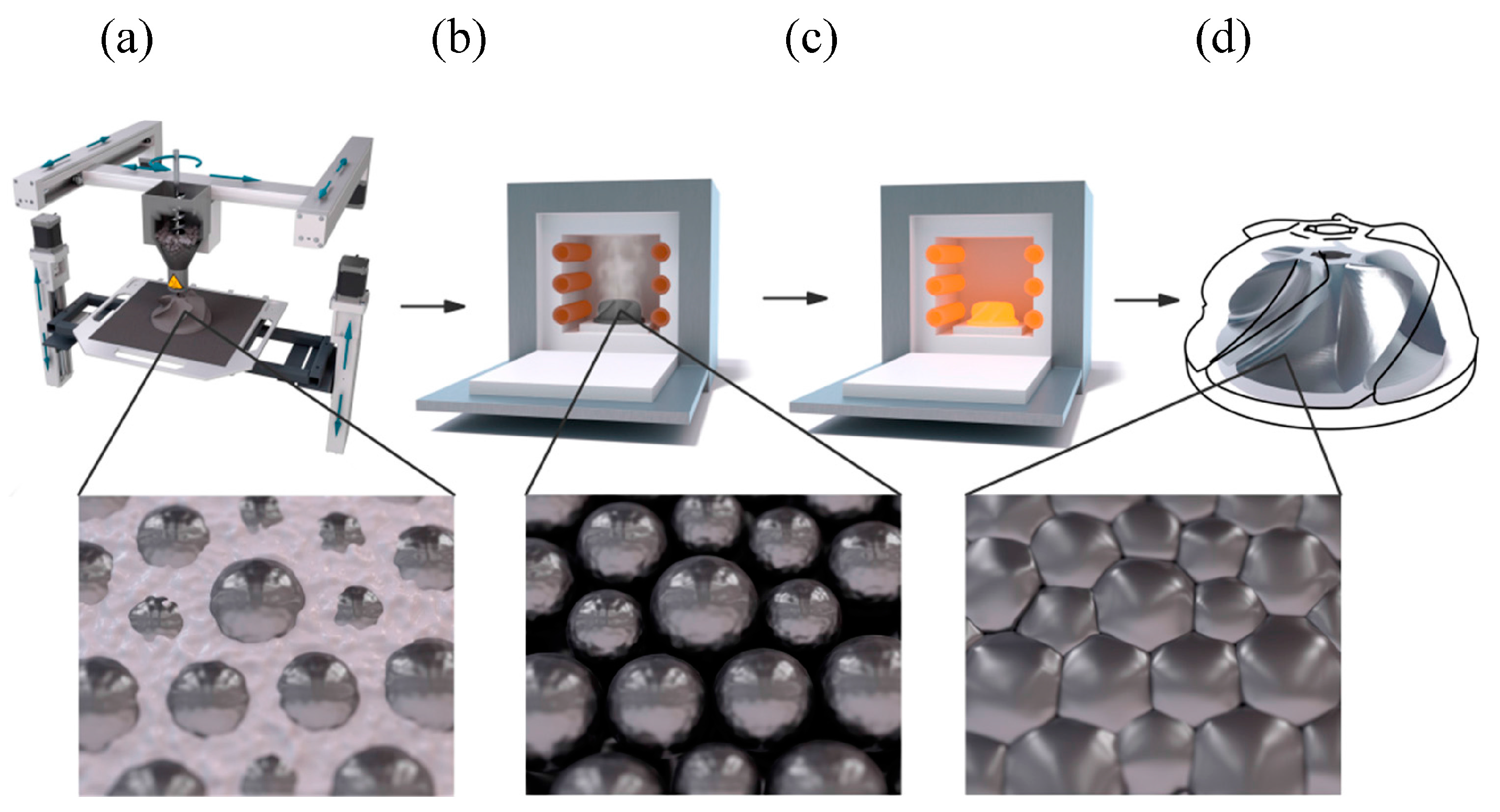
Figure 2.
Sintering cycle for Catamold® 17-4PH F.

Figure 3.
(a) Printed cylinders for geometrical and mechanical investigations; (b) turned cylinders for density investigation.
Figure 3.
(a) Printed cylinders for geometrical and mechanical investigations; (b) turned cylinders for density investigation.
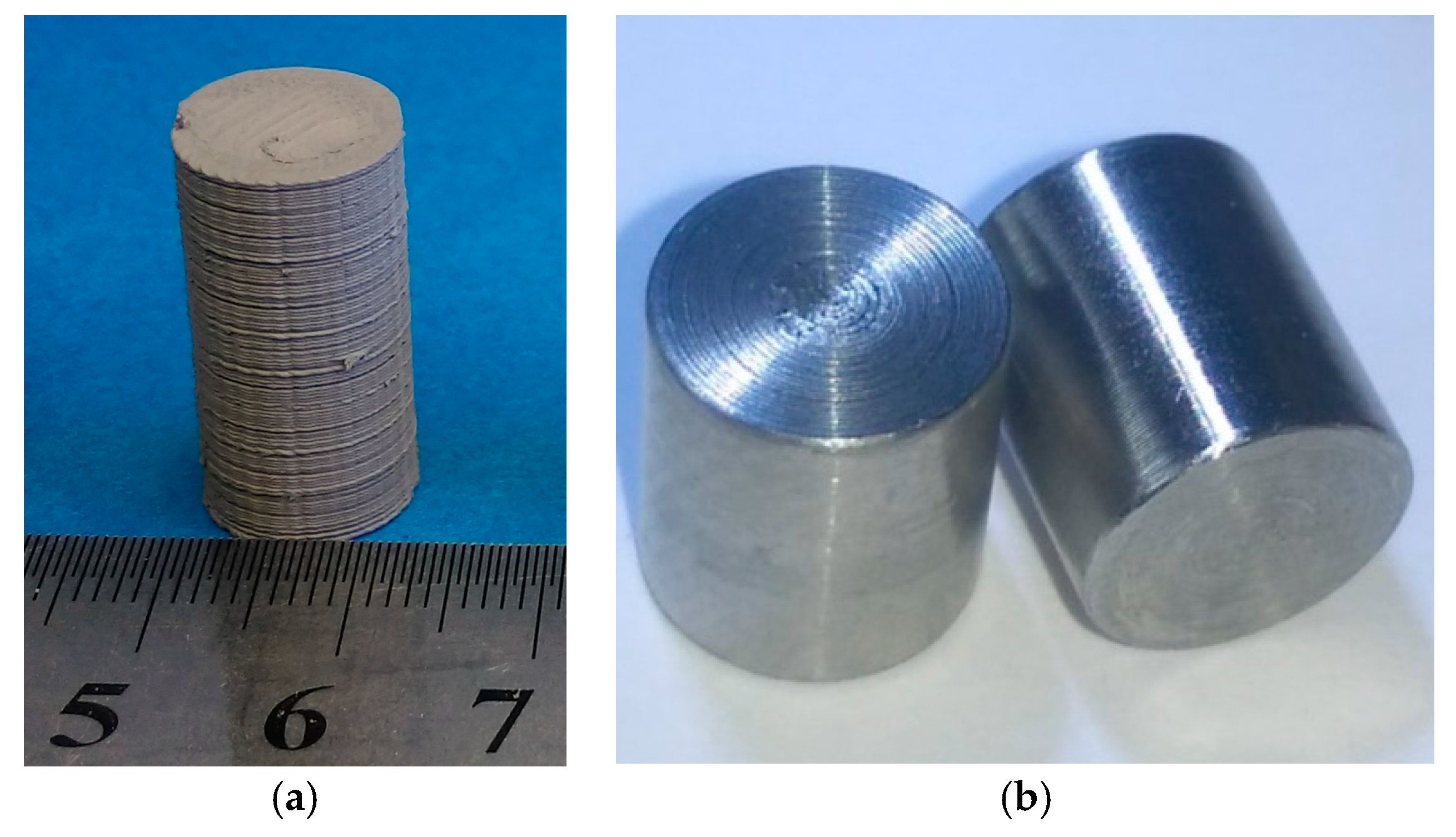
Figure 4.
Compressive strength σd0.2, σdm40 and σdm50 in relation to infill.

Figure 5.
(a) Tested cylinder with 100% infill; (b) tested cylinder with 0% infill.

Table 1.
Printing parameters.
| Parameter | Value |
|---|---|
| Extruder temperature | 215 °C |
| Bed temperature | 115 °C |
| Nozzle diameter | 0.5 mm |
| Layer height | 0.2 mm |
| First layer height | 0.25 mm |
| Infill type | rectilinear |
| Infill angle | 45° |
| Speed | 20 mm/s |
Table 2.
Technical data of Catamold® 17-4PH F.
| Parameter | Typical Value | Test Method |
|---|---|---|
| Mould Flow Index (MFI) | 700 g/10 min | ISO 1133 (190 °C, 21.6 kg) |
| Density (after sintering) | 7.67 g/cm3 | ISO 3369 |
| Oversizing factor | 1.1669 | RC/PQ-SH-1360 |
| Extrusion temperature | <200 °C | - |
Table 3.
Geometrical properties, mass and density of printed bars (n = 6).
| Parameter | Height | Width | Length | Volume | Weight | Density |
|---|---|---|---|---|---|---|
| (mm) | (mm) | (mm) | (mm3) | (g) | (g/cm3) | |
| Greenpart | 5.70 ± 0.22 | 11.6 ± 0.022 | 136.7 ± 0.12 | 9008 | 41.2 ± 1.24 | 4.57 |
| Sintered part | 4.74 ± 0.18 | 9.87 ± 0.09 | 116.7 ± 0.31 | 5460 | 37.6 ± 1.13 | 6.90 |
| Shrinkage in % | 16.8 | 14.7 | 14.6 | 39.4 | 8.66 | - |
| Oversizing factor | 1.20 | 1.17 | 1.17 | 1.65 | - | - |
Table 4.
Geometrical properties, mass and density of cylinders with 100% infill (n = 6).
| Parameter | Height | Diameter | Volume | Weight | Density |
|---|---|---|---|---|---|
| (mm) | (mm) | (mm3) | (g) | (g/cm3) | |
| Greenpart | 22.7 ± 0.8 | 11.8 ± 0.067 | 2484 | 12.1 ± 0.42 | 4.86 |
| Sintered part | 19.1 ± 0.05 | 10.1 ± 0.12 | 1513 | 11.0 ± 0.39 | 7.28 |
| Shrinkage in % | 15.9 | 14.9 | 39.1 | 8.64 | - |
| Oversizing factor | 1.19 | 1.18 | 1.64 | - | - |
Table 5.
Density of turned cylinders with 100% infill (n = 3).
| Height | Diameter | Volume | Weight | Density |
|---|---|---|---|---|
| (mm) | (mm) | (mm3) | (g) | (g/cm3) |
| 10.0 ± 0.02 | 8.95 ± 0.02 | 632.79 | 4.71 ± 0.01 | 7.47 |
Table 6.
Compressive strength in relation to infill percentage (n = 6).
| Infill in % | 0% | 20% | 40% | 60% | 80% | 100% |
|---|---|---|---|---|---|---|
| σd0.2 in MPa | 625 ± 97 | 740 ± 52 | 816 ± 22 | 874 ± 36 | 927 ± 72 | 922 ± 138 |
| σdm40 in MPa | 1040 ± 53 | 1339 ± 25 | 1540 ± 36 | 1703 ± 49 | 1893 ± 121 | 1961 ± 134 |
| σdm50 in MPa | 1220 ± 90 | 1543 ± 76 | 1783 ± 56 | 2024 ± 63 | 2271 ± 148 | 2345 ± 168 |
© 2018 by the authors. Licensee MDPI, Basel, Switzerland. This article is an open access article distributed under the terms and conditions of the Creative Commons Attribution (CC BY) license (http://creativecommons.org/licenses/by/4.0/).
Share and Cite
MDPI and ACS Style
Lieberwirth, C.; Sarhan, M.; Seitz, H. Mechanical Properties of Stainless-Steel Structures Fabricated by Composite Extrusion Modelling. Metals 2018, 8, 84. https://doi.org/10.3390/met8020084
AMA Style
Lieberwirth C, Sarhan M, Seitz H. Mechanical Properties of Stainless-Steel Structures Fabricated by Composite Extrusion Modelling. Metals. 2018; 8(2):84. https://doi.org/10.3390/met8020084
Chicago/Turabian StyleLieberwirth, Clemens, Mohamed Sarhan, and Hermann Seitz. 2018. "Mechanical Properties of Stainless-Steel Structures Fabricated by Composite Extrusion Modelling" Metals 8, no. 2: 84. https://doi.org/10.3390/met8020084
Note that from the first issue of 2016, this journal uses article numbers instead of page numbers. See further details here.