Article

An Efficient Approach to Address Issues of Graphene Nanoplatelets (GNPs) Incorporation in Aluminium Powders and Their Compaction Behaviour

1
Department of Mechanical Engineering, Universiti Teknologi PETRONAS, 32610 Bandar Seri Iskandar, Perak, Malaysia
2
Department of Fundamental and Applied Sciences, Universiti Teknologi PETRONAS, 32610 Bandar Seri Iskandar, Perak, Malaysia
3
Sustainable Energy Technologies Center, College of Engineering, King Saud University, Riyadh 11421, Saudi Arabia
4
Department of Chemical Engineering, College of Engineering, King Saud University, Riyadh 11421, Saudi Arabia
*
Author to whom correspondence should be addressed.
Metals 2018, 8(2), 90; https://doi.org/10.3390/met8020090
Submission received: 12 October 2017 / Revised: 31 December 2017 / Accepted: 22 January 2018 / Published: 25 January 2018
(This article belongs to the Special Issue Metallic Materials and Manufacturing)

Abstract

:
The exceptional potential of the graphene has not been yet fully translated into the Al matrix to achieve high-performance Al nanocomposite. This is due to some critical issues faced by graphene during its processing such as the dispersion uniformity, structure damage, compatibility/wettability, and low graphene embedding content in Al matrix. In the present work, a new integrative method was adopted and named as “solvent dispersion and ball milling” (SDBM) to address the issues above efficiently in a single approach. This strategy involves effective graphene nanoplatelets (GNPs) solvent dispersion via surfactant decoration and solution ball milling employed to polyvinyl alcohol (PVA) coated Al with various GNPs content (0.5, 1 and 1.5 wt. %). Flaky Al powder morphology attained by optimizing ball milling parameters and used for further processing with GNPs. Detailed powders characterizations were conducted to investigate morphology, graphene dispersion, group functionalities by FTIR (Fourier transform infrared spectroscopy) spectroscopy and crystallinity by powder XRD (X-ray diffraction)analysis. Compaction behaviour and spring back effect of the GNPs/Al powders was also investigated at different compaction pressure (300 to 600 Mpa) and varying GNPs fractions. In response, green and sintered relative density (%) along with effect on the hardness of the nanocomposites samples were examined. Conclusively, in comparison with the unreinforced Al, GNP/Al nanocomposite with 1.5 wt. % GNPs exhibited the highest hardness gives 62% maximum increase than pure Al validates the effectiveness of the approach produces high fraction uniformly dispersed GNPs in Al matrix.

1. Introduction

From last few decades, Aluminum matrix nanocomposites (AMNCs) reinforced with carbon nanofillers, such as CNTs and graphene, have attracted a great attention of the potential users such as automotive and aerospace sectors. AMNCs possess the full potential to satisfy the demands of the industries due to the extraordinary properties of the nanofillers translated into the metal matrix. This combination leads to AMNCs with lightweight, high mechanical and thermal properties suitable for many structural and thermal management applications [1]. Among carbon nanofiller, low-density graphene or graphene nanoplatelets (GNPs) possess perfect 2D honeycomb carbon arrangement considered as next-generation reinforcement for metals. A substantial amount of work is in progress to incorporate graphene into the Al matrix to get the full benefit of reinforcement due to its 2D sheet nature with sp2-type covalently strongly bonded carbon lead to high surface area and excellent mechanical properties [2]. Therefore, many researchers have attempted to incorporate graphene into Al matrix and obtained enhanced mechanical properties of graphene/Al matrix composite [3,4]. Despite constant efforts, the reinforcing effects of graphene in Al matrix are still notably lower than the theoretically predicted result. It is due to the multiple issues facing graphene in Al matrix during processing as summarized in Figure 1.
The above-highlighted issues of graphene are usually concerned with: (1) uniform dispersion (a prime necessity for full strengthening potential and enhance the mechanical properties; (2) Structural retention (an assurance to translate graphene properties to the composite); (3) Compatibility/Wettability (a strong interface with proper compatibility to ensure proper load transfer); (4) Low fraction addition (high concentration could lead to maximum strengthening and maximum increase in mechanical properties). Notable, many researchers reported enhancement of Al nanocomposite properties via favorable graphene dispersion but at low fraction addition mainly up to 0.5 wt. % [5,6,7,8] and few reports for 1 wt. % graphene in Al matrix. The reason for such low fraction graphene addition is due to graphene higher surface area and agglomeration problem at higher graphene contents.
Noteworthy, many researchers paid their most attention to disperse graphene in Al matrix, however, at the expense of deteriorating its structure following succeeding techniques. The including techniques are high energy ball milling (dry or wet), flake powder metallurgy, colloidal processing, molecular level mixing and nanoscale dispersion technique and so forth to address individual problems [9,10,11,12]. Zhang et al. [13] fabricated Al5083 alloy with graphene nanoplatelets (0.5 and 1.0 wt. %) by high energy ball milling. They reported an increase in mechanical properties on the other hand also accompanied unwanted reaction product due to the damaged structure of graphene during processing. Bustamante et al. [14] studied the effect of milling time on the GNPs (0.25, 0.50 and 1.0 wt. %) dispersion in Al matrix composite. Recently, Bisht et al. [15] synthesized graphene nanoplatelets reinforced aluminium composite by using probe sonication for dispersion and mechanical mixing. Khan et al. [16] employed a combination of the sonication dispersion and ball milling of dried GNPs/Al composite powder for uniform dispersion. Liu et al. [17] used graphene nanosheets (0.07, 0.15 and 0.3 wt. %) to reinforced aluminium matrix by sonication and mechanical mixing processing. Hence it can be seen that researchers have mainly adopted powder metallurgy route and focused on graphene dispersion on metal matrix with individual approaches.
In this research, issues emphasized in Figure 1 were addressed by adopting integrative methodology named as solvent dispersion and ball milling (SDBM) processing. In this approach, GNPs solvent dispersion and solution ball milling with PVA coated Al powders combination were adopted to obtain nanocomposite powders with a various fraction of GNPs. Detail characterizations were carried out on GNPs/Al powders to validate the effectiveness of the approach to address issues efficiently. In addition, developed nanocomposite powders characteristics and their compaction behaviour at various pressures were also studied. Furthermore, the influences of compaction pressures on GNPs/Al green and sintered samples gauged by measuring relative densities (%) along with effect on hardness were assessed.

2. Materials and Methods

Atomized spherical pure Al powder (99.7% purity, mean size 10 μm) purchased from CNPC powder group Co. Ltd., Shanghai China as shown in Figure 2a. As reinforcement, high-quality Graphene nanoplatelets (GNPs) having 99.5% carbon, 10–15 nm thickness with 6–26 µm length were obtained from Ugent Ltd., Selangor, Malaysia. Figure 2b presents the SEM image of the graphene nanoplatelets plate-like morphology consists of 10–15 graphene layers in stack form. A more detailed observation of GNPs morphology is presented in the TEM image (Figure 2c) showed low defect and few-layer GNPs stacking sheets.

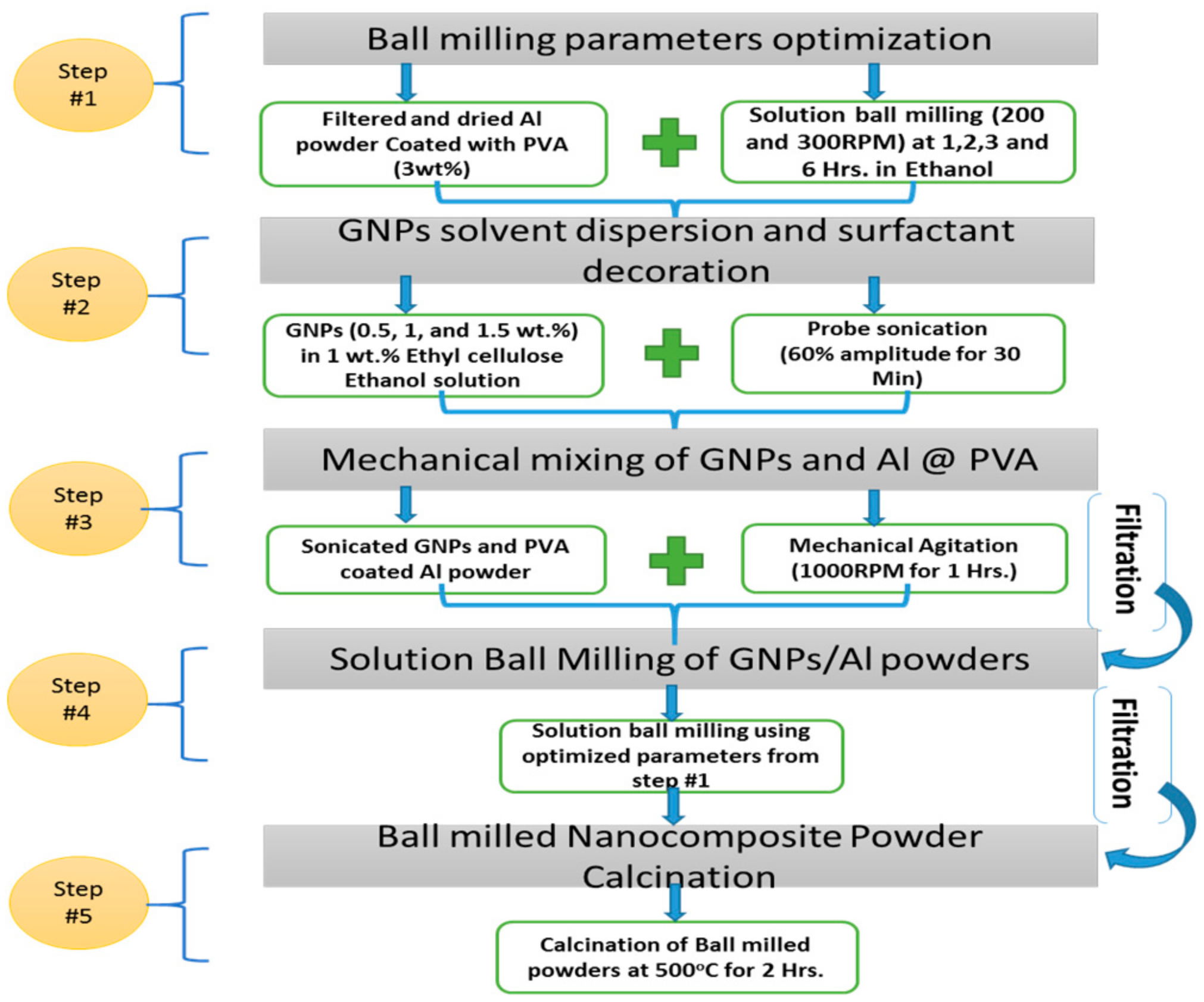
2.1. GNPs/Al Nanocomposite Powder and Samples Formation

Figure 3 represents the SDBM process develop in this study to address the issues exist in GNPs reinforced Al matrix composites. The processing of the GNPs/Al powder was performed in five successive steps. The first step is related to the solution ball milling parameter, i.e., 200 and 300 RPM and milling times (1, 2, 3 and 6 h.) optimization of the 3 wt. % polyvinyl alcohol (PVA) coated Al powders. This can be done purposely to get flake type morphology at specified parameters. The second step is the decoration of the different GNPs concentration (0.5, 1 and 1.5 wt. %) with 1 wt. % ethyl cellulose surfactant using probe sonication. The third step is the addition of the freshly prepared dry PVA coated Al powders into the dispersed solution of as prepared GNPs-surfactant. The solutions were mechanically agitated at 1000 rpm for 1 h. Figure 4 represents the visual observation of the mechanically agitated surfactant assisted sonicated GNPs incorporation into the PVA coated Al (PVA @ Al) solutions along with vacuum filtered powder ready for next step processing. Firstly, EC surfactant dissolves in an ethanol solvent to get a complete miscible solution. EC surfactant is decorating GNPs surface via sonication aid and responsible for effective GNPs dispersion and exfoliation in an ethanol solvent. Next to that is the GNPs sonicated solution showed highly dispersed solution with GNPs as verified by its dark colour appearance. Then, PVA @ Al powder is mixed to GNPs sonicated solution for mechanical mixing as depicted in Figure 4. After mixing, vacuum filtration of the GNPs/Al solution is carried out to acquire GNPs/Al powder.
In the next processing step, proposed solution ball milling by Chen et al. [18] was employed to the filtered GNPs/Al powder to assist GNPs dispersion further. The milling parameters were used as per step 1 optimization for flake type morphology and keeping in view the mild parameters to intact GNPs structure. After subsequent milling process, GNPs/Al powders were vacuum filtered and dried to remove the solvent. In the final stage of powder fabrication, calcination of the composite powders was carried out to decompose PVA and surface ingredient which can be detrimental to composite properties. Lastly, different fractions of GNPs/Al composite powders produced were compacted at various compaction pressures (300, 400, 500 and 600 Mpa) using steel die in Hydraulic Press (3000 kN) to obtain 30 mm Dia and 5 mm thick disc type samples. Finally, samples were consolidated at 620 °C under N2 atmosphere hold for 2 h using 5 °C/min dwell time. After furnace cooling samples were subjected to further characterization.

2.2. GNPs/Al Nanocomposite Characterization

The morphological state of the raw materials, ball milled and dispersed nanocomposite powders after processing were studied by scanning electron microscopy (SEM) (Phenom-Pro X, Eindhoven, The Netherlands) and FESEM (Zeiss Supra 55VP, Oberkochen, Germany) equipped with EDS analysis to detect element presence. The particle size and distribution of the dry nanocomposite powders were carried out by laser diffraction using (Malvern Mastersizer 2000, Worcestershire, UK) following ASTM standard B822-02. The aspect ratio of the powder particles was calculated measuring diameter to thickness ratio (d/t) of 10 particles of each batch and average reported. Apparent density and flowability of the powders were also determined by repeated three times, and average values were recorded. The Fourier transform infrared spectroscopy (FTIR) was performed by (Agilent ATR-FTIR, Santa Clara, CA, USA) in the region of 400−4000 cm−1 with resolution 4 cm−1 to investigate the related agents after surface treatment of Al and nanocomposite powders. X-ray diffraction (XRD) analysis was conducted by using (PANalytical X’pert, Almelo, The Netherlands), equipped Cu-Ka with λ = 0.154 nm) using 10–90 °C scan range and 1°/min step size to study initial Al powder, GNPs and nanocomposite powders. Green densities of the compacted samples were carried out by diameter and thickness dimensions of the compacted samples to evaluate GNPs incorporation effect at various compaction pressure. Relative green densities (%) measured by dividing compact green density (g/cm3) by theoretical density of the Al powder (2.7 g/cm3) and nanocomposite powders calculated via rule of mixture. Sintered densities of the pure Al and nanocomposite samples measured by using Archimedes’ Principle via standard test method (ASTM B962-17). The average values were taken by measuring three samples of each batch of powders. Using Vickers hardness tester (Leco LM 247AT, Saint Joseph, MO, USA), micro hardness of the polished sintered samples was calculated by applying 200 gf with 15 s dwelling time via standard test method (ASTM E92-82). At least five values were recorded for each sample and averaged.

3. Results and Discussion

3.1. Optimizing Solution Ball Milling Parameters for PVA @ Al Powder and Morphological Analysis

The primary aim of adopting solution ball milling approach is to obtain a uniform dispersion, flaky morphology and strong intactness of GNPs on Al surface. Figure 4 and Figure 5 present morphological changes of the PVA coated Al powder after ball milling at (200 and 300 rpm) and various time duration (1, 2, 3 and 6 h). Bustamante et al. [19] highlighted the effect of milling time on the dispersion of CNTs in Al alloy and its effect on the hardness of the nanocomposite. Therefore, optimizing milling time is important to get quality dispersion of the nanoparticles in the metal matrix. It can be seen in Figure 5; the spherical Al powder gets flattened with an increase of time, which was the effect of shearing effect of the balls as also reported by Liu et al. [20]. As shown in Figure 5, at the rotation speed of 200 rpm, the milling time increased up to 1 h; ductile aluminum particles started to flatten having high aspect ratios started to form. With further increase in milling time (2 h), plastic deformation was more pronounced which resulted in the formation of high aspect ratio (large dia and low thickness) particles having flake-like shape [21]. However, further increasing time lead to high particle deformation and resulted in considerable morphological change [22]. At last at higher milling time (6 h), milling imposes fracturing of particles initiated due to strain hardening, and brittle Al powders lead to irregular and equiaxed shape particles with smaller particles as also depicted in Figure 5. This type of particles behaviour under ball milling also highlighted by Fogagnolo et al. [23].
Similarly, Figure 6 demonstrates the morphological state of the PVA coated Al powder ball milled at 300 rpm. Rikhtegar et al. [21] claimed that rotation speed parameter is more operative than the time led to high deformation mechanism of Al powder. It is observed that with increasing speed (300 rpm), impact forces also increase which led to increasing number of flaky powders even at 1 h milling. After 2 h of milling, powders readily reached to highest flattening rate. Soon after 2 h milling, particles severely cold welded together and formed a large particle of irregular shape. At the end of 6 h milling, particles again experience high impact forces and get flattened with thick cake type particles as can be observed in Figure 6. So overall, milling time up to 2 h at both rotation speed is feasible to obtain flake type Al particles which can be considered as the optimized for ball milling. This conclusion is also exact in accordance with the previous studies results [24].
To verify our above assertion, particle size, distribution and aspect ratios of the milled powders were measured. Generally, higher the particle size and aspect ratio, higher will be the flaky morphology of the powders. As can be seen in Figure 7a, at a rotation speed of 200 rpm, maximum particle size received after 2 h of milling corresponds to flake particles morphology. With an average thickness of 2.08 μm and the mean diameter of 66.9 μm (aspect ratio of 32.16 μm) was obtained and evidently seen in SEM results (Figure 5). After 2 h of milling, particle size starts to reduce due to particles strain hardening lead to fracturing emerge large number small particle size. On the other hand, the rotation speed of 300 rpm (Figure 7b) readily raised the particle size from the first hour of milling up to 2 h resulted from particles flattening shape as depicted from particle size compared to a particle size of 200 rpm (Figure 7a). After 3 h of milling, particle size reaches to maximum size due to cold welding of particles of having an irregular shape having an average thickness of 1.51 μm and the mean diameter of 127 μm (aspect ratio of 84.11 μm) as shown in Figure 6. Lastly, higher milling time (6 h) at 300 rpm, a size of particles abruptly reduces due to the fracturing of particles under high shearing forces of milling balls which can be evidently seen in Figure 6. It is also important to note that both rotation speeds exhibited different particle size distribution. The most commonly used metrics when describing particle size distributions are D-Values (D10, D50 and D90) which are the intercepts for 10%, 50% and 90% of the cumulative mass and taken as volume distribution. At a speed of 200 rpm, D90 shows particle population less than 90 μm whereas at 300 rpm the particles are of mostly up to 150 μm size at d90. This can clearly indicate the effect of milling speed on the particle size evaluation.

3.2. GNPs/Al Nanocomposite Powder Formation

Analyzing the SEM results and particle size of the solution ball milled PVA coated Al powder from Figure 5, Figure 6 and Figure 7, the optimized time to obtain flaky morphology of the powders is 2 h of milling either at 200 rpm and 300 rpm. Therefore, to proceed with optimized milling speed and time, we selected mild conditions i.e., 2 h at 200 rpm as the desired parameter for processing of GNPs/Al composite powder. Figure 8a–d displays the SEM images exhibited morphologically and dispersion analysis of the dry PVA coated pure Al (Figure 8a) and dried mechanically mixed GNPs/Al composite powder with GNPs fractions of 0.5, 1 and 1.5 wt. % (Figure 8b–d) underwent solution ball milling. Firstly, all images depict the flaky as a general morphology for pure Al and all GNPs/Al powders also observed by Bustamante et al. [14]. At higher GNPs content (Figure 8d), some non-flake powders were also seen which can be attributed to reducing plastic deformation of Al powder. This happens due to decreased ball collision in solution and GNPs lubrication effect which acts as process controlling agent (PCA) in the ball milling process as also reported by Varol et al. [11,25]. Secondly, Ball milling is a well-known technique to disintegrate the graphene agglomerates due to the involvements of the high collision of balls impact. Furthermore, this processing effectively embed the graphene within Al powder or strongly attach the graphene to the surface [8,13,26]. Following the same strategy, in this work, solution ball milling effectively embedded the GNPs within Al powder which can be validated with the fact that no agglomerations were seen within Al powders as also confirmed by images of the all GNPs/Al powder mixture and in accordance with previous studies [27,28]. Another important aspect is the incorporation of GNPs at high content (1.5 wt. %) successfully embedded or strongly attached to the Al powder surface due to high surface available by flake shape.
In addition, the presence of PVA on the Al surface also played a vital role by forming hydrogen bonding with the decorated surfactant (ethyl cellulose) on GNPs surface to assist strongly attachment on the Al surface [29,30]. Due to nanosized and thickness, no visible graphene can be seen on the Al surface, therefore, EDS of the respective composite powders were carried out (as shown by arrows). It is important to highlight that PVA and surfactant presence were neglected as they have been completely removed after calcination. As illustrated in images showing EDS analysis, the presence of carbon evidently proves the GNPs existence. Noteworthy, atomic percentage of the carbon also increases with increase in GNPs concentration in the composite powder. So the authors can confidently claim that GNPs presence assures uniform distribution along with strongly attached to the flaky Al powder particles. Figure 9 demonstrates the 1.5 wt. % GNPs/Al composite powder morphology after milling operation along with a magnified view of the flaky shape powder having a diameter of 108.3 µm and thickness of 2.937 µm. Besides, high-resolution image of the attached GNPs can also be seen on the surface of the flaky Al powder.

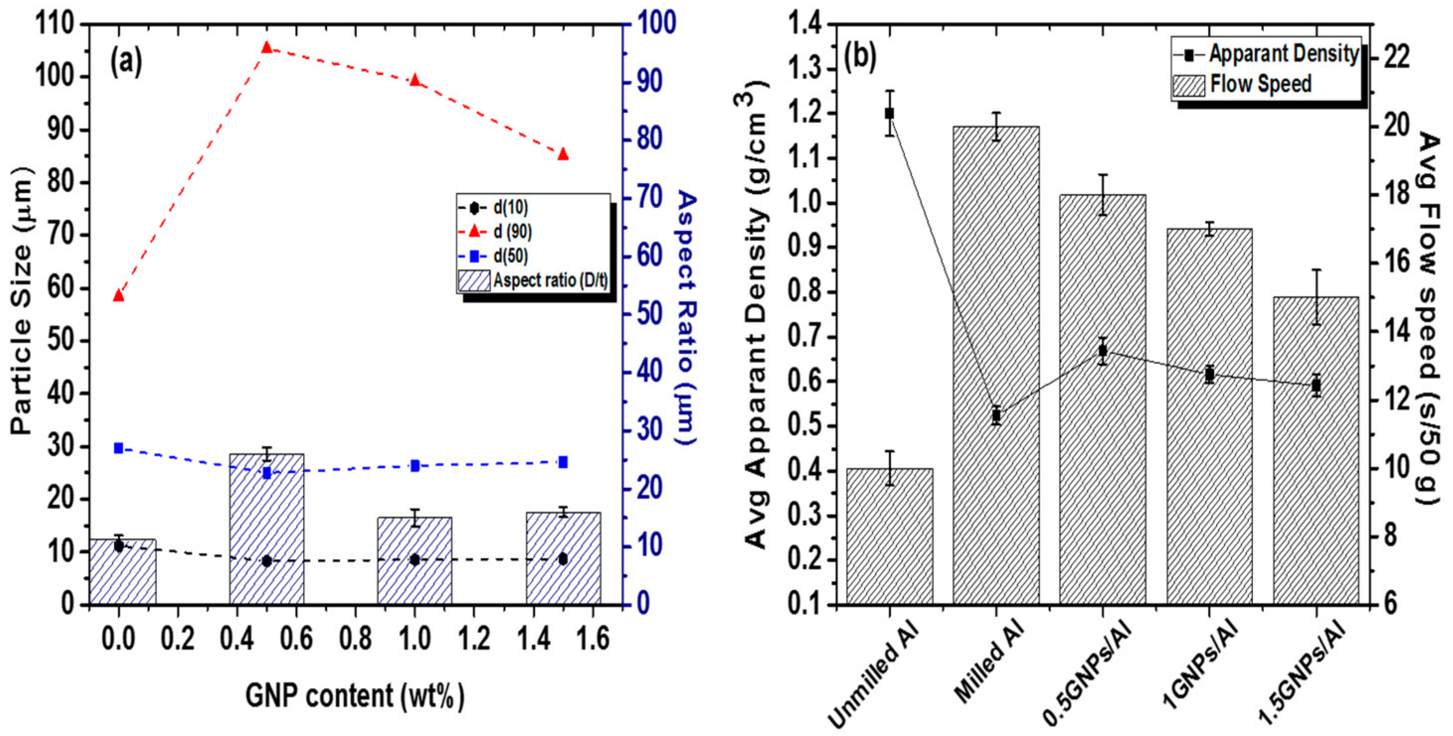
3.2.1. Particle Size and Powder Characteristics Analysis

Figure 10a displays change of average particle size distribution (D10, D50 and D90) of GNPs/Al nanocomposite powders. It is observed that with increasing GNPs particle content in Al powder, the particle size distribution (D10 and D50) reduced gradually, while D90 composite powder shows an abrupt decrease in particle size. This can be attributed to the increased number of GNPs particles in the composite powder mixture. It is shown that average particle size of the Al nanocomposite powders increases during milling process as compared to an initial particle size of as received Al matrix powder. This behaviour can be related to the formation of the composite powder flake morphology under subsequent milling processing. Similarly, the aspect ratio (Diameter/Thickness) of the particles was also calculated by determining their respective particles diameter and thickness after milling processing. It is also observed in Figure 10a that aspect ratio of the nanocomposite powder of GNPs (0.5 wt. %) increases to 25.56 µm as compared to initial Al particles aspect ratio (11.20 µm), which again confirms the evolution of flaky shape after the milling process. Though the aspect ratio of other GNPs content (1 and 1.5 wt. %) higher than initial Al powder decrease with increasing content which is due the GNPs lubrication effect provided hindrance for plastic deformation and resist to develop flake shape nanocomposite at higher content.
Figure 10b represents the results of the apparent density and flowability of powders suggests that they are affected mainly by the particle shape change to flake shape formation. As can be seen, initial raw pure Al powders showing the highest value of 1.2 g/cm−3 (45% of the density of wrought aluminium) deduced the higher the degree of its sphericity. However, on the other hand, pure Al after milling, apparent density reduces due to morphological transformation to flake shape significantly reduce the powder packing and provide significant interparticle friction [31]. Likewise, nanocomposite powders show lower apparent density with increasing GNPs content and as compared to milled pure Al powder. Apparently, milling powders morphology was same, apparent density can only change by GNPs content and increasing particle size than initial matrix powders [32]. During milling, GNPs effectively attached on the Al surface but not embedded within Al particles which accorded friction during particle rearrangement caused a decrease in apparent density [33]. Higher the GNPs content lower is the powder packing due to high friction results in lowering of apparent density couple with flaky shape morphology. Raw Al powders show high flowability due to spherical morphology whereas milled Al and nanocomposite powders show low flowability strongly favors morphological transformation dependency.

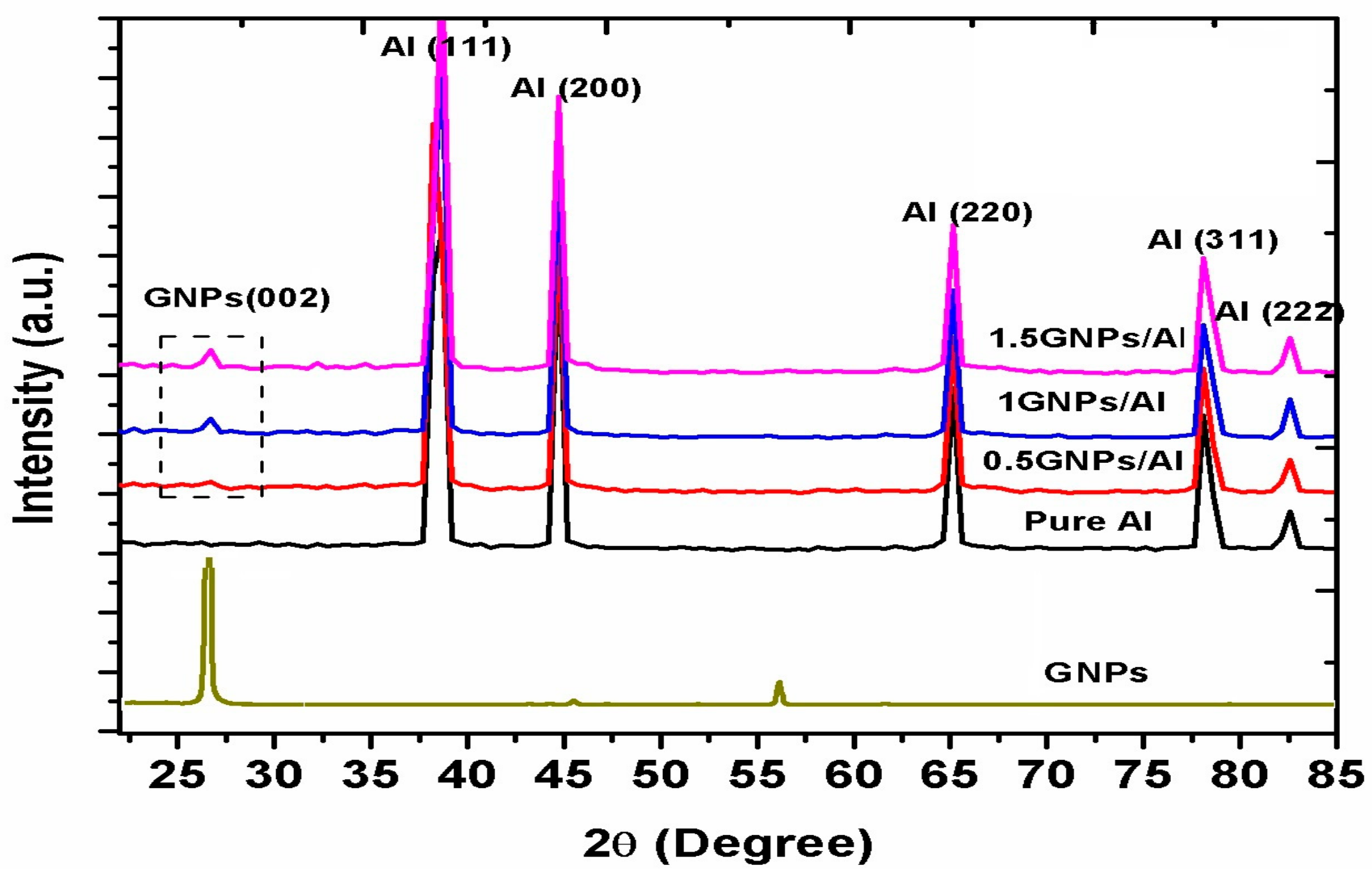
3.2.2. FTIR Spectroscopy and XRD Analysis of the Powders

In this strategy, PVA coated Al powders are used to reduce the Al powder surface energy and enhance compatibility/wettability of the Al powders for maximum GNPs adsorption on the surface during mechanical mixing and milling processing. PVA modification is an essential aspect of getting GNPs uniform adsorption on Al surface since un-treated Al surface possess very poor wettability as reported by Jiang et al. [34]. Therefore, PVA modified Al powders guarantee the high interaction of GNPs with Al powders as its hydrophilicity is improved to accomplish uniform distribution and to develop strong interaction between them. It should be noted that even after pyrolysis of PVA membranes from Al powder, nanoparticles were well retained on the surface [30]. In this regard, the presence of PVA membranes on the Al surface must be detected after modification and the retention of the membranes after subsequent mixing and milling processing is noteworthy. Figure 11 presents the FTIR of the PVA coated Al powders after successful modification; ball milled PVA coated Al powders at different rotation speed, PVA modified Al/GNPs nanocomposite powder and after PVA calcination. The presence of the C–H stretching and bending at 2920 and 2853 cm−1, C–O stretching vibrations (1050 cm−1) and C–OH stretching and vibrations (3000–3500 cm−1) evidently confirms the Al surface modification by PVA and preservation of membrane after milling processing [35]. In Figure 11, the characteristic peaks of the OH stretch and bend vibration of PVA are almost absent, validating that the PVA has been eliminated during the pyrolysis process [36].
Figure 12 presents the XRD spectra of the solution ball milled pristine Al powder and as produced GNPs/Al composite powder with different GNPs fractions. The composite samples have major peaks corresponding to Al at 2θ = ~38.74° (111), ~44.96° (200), ~65.29° (220), ~78.29° (311), and ~82.81° (222), respectively. Except that, there is no detectable second phase, i.e., Al3C4 and Al2O3 indicating, that all powders were not oxidized in the process of ball milling. It is worth noticing that carbon peak of graphene at 2θ = ~26.57° (002) was found in all composite powder samples (marked by dash block). The intensity of the carbon peak increases with increasing content of the GNPs. Similarly, the intensity of GNPs/composite powders with different GNPs content is higher than of pure Al powder which is attributed to the presence of graphene in the composite [15].

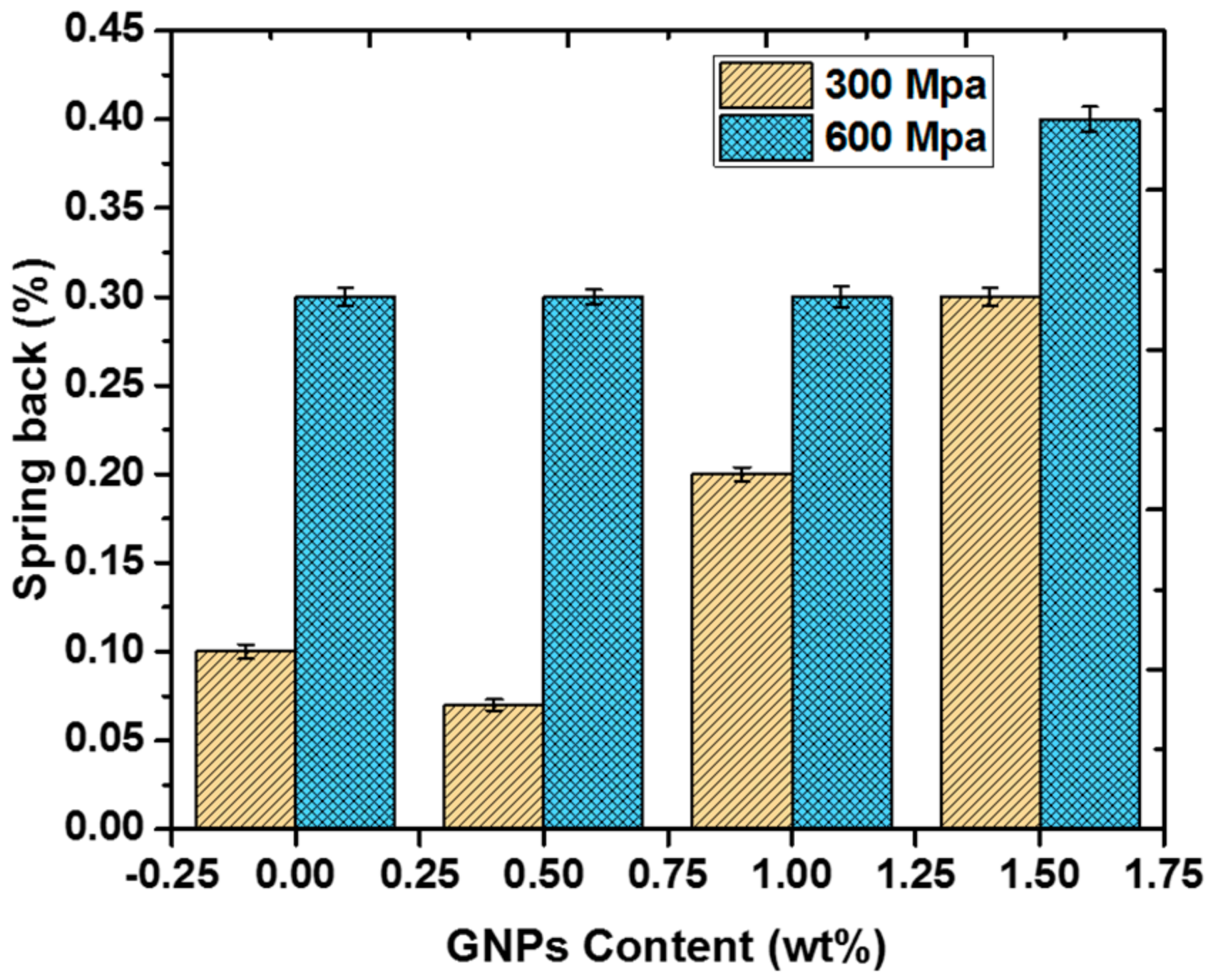
4. Compaction Behavior of GNPs/Al Nanocomposite

Compaction behaviour of milled, unmilled pure Al and nanocomposites powder was also testified at various compaction pressures (from 300 to 600 Mpa) and varying GNPs content (0.5, 1 and 1.5 wt. %) as shown in Figure 13a,b. As expected, green density (%) of all samples in Figure 3a increases with increasing compaction pressure due to particles rearrangement, decrease in the distance between the Al powder particles, and reduction of porosity with pressure [11,37]. Meanwhile, unmilled spherical Al powder exhibited the highest value of green density due to their good compressibility feature. Whereas, milled pure Al powder and GNPs/Al nanocomposite powder displayed decreasing compaction behaviour (shown by the downward arrow). This type of response can be ascribed to the (i) Morphological transformation from spherical to flake type; (ii) Mechanical interlocking and cold-welding inhibition between the Al powders due to GNPs presence; (iii) Powders characteristics (such as poor flowability) and enhance plastic deformation capacity. As can be observed that green density of 0.5 and 1 wt. % GNPs/Al exhibited the same trend up to 400 Mpa than at higher pressures. The 1.5 wt. % GNPs samples present the lowest green density (%) at all compaction pressures which could be due to the increased no of GNPs particles in the Al powder and their presence ultimately hinders the nanocomposite compaction as also reported by Seo et al. [38]. Another possible reason may be due to the graphene re-agglomeration at higher content as GNPs particles get close to each other. Figure 13b depicted the green density (%) outcome with different GNPs fractions. It can be seen that pure Al has the highest green density (%) whereas green density (%) decreases with increasing GNPs fraction at all compaction pressure. Further, green density (%) increases due to increase compaction behaviour with rising in GNPs fraction (as shown by the upward arrow). For example, at higher GNPs content i.e., 1.5 wt. %, green density increases from 87.8 to 92.2%. Similar kind of behaviour can be observed at other GNPs fractions (0.5 and 1 wt. %). Such improvement can be attributed to the GNPs effective dispersion and presence which effectively filled the gaps between powder particles.
Spring back (%) response of samples at different compaction pressure was also measured as shown in Figure 14. Spring back of the green compacts was calculated just after removal of compaction pressure and ejection of the compacts from die. % Spring back was measured according to the formula [39];
S (%) = 100 (λC − λD)/λD
where S (%) = Spring back (%), λC = transversal dimension of the (ejected) compact, λD = corresponding dimension of the compaction die (after ejection of the compact). It can be seen that spring back (%) found to be increased with increased GNPs fraction and compaction pressure (from 300 to 600 Mpa). Increased content of GNPs had resulted in the greater amount of elastic recovery, which resulted in higher spring back (%) value for high GNPs content in Al compacts and also observed when compaction increased from 300 Mpa to 600 Mpa. High spring back (%) shown by nanocomposite compacts at all pressures could be due to the GNPs low compressibility characteristics. Therefore, GNPs content has become the prominent factor for such higher spring back (%) of the GNPs/Al green compact.

5. Physical and Mechanical Properties of the Sintered GNPs/Al Nanocomposites

Figure 15a presents relative densities of the sintered samples at various compaction pressure. Pure Al and nanocomposites samples density decreases with increasing compaction pressure. Pure ball milled Al has shown lowest green density as compared to nanocomposite samples at all pressures. Interestingly, 0.5 wt. % GNPs/Al exhibited highest sintered density than 1 and 1.5 wt. % GNPs at all pressures. Similarly, sintered density of all samples decreases with increasing pressure. Figure 15b demonstrate increment of the sintered density from pure Al to 0.5 wt. % GNPs/Al samples then start decreasing with the rise in GNPs content. At compaction pressure 300 Mpa, highest sintered density was achieved for all samples and decrement in relative density was observed until 600 Mpa pressure. Such decreasing trend of sintered densities of pure Al and GNPs/Al samples in Figure 15a,b can be attributed to the presence of the low-density GNPs particles as also reported by Rashad et al. [40]. It can also be due to the uniform dispersion of GNPs in Al matrix which did not hinder during sintering operation and filled the gaps adequately which increased the density of nanocomposites than pure milled Al. High densities of nanocomposite than pure Al validates the good sinterability achieved at all pressure. It can be seen in Figure 15b, 1 and 1.5 wt. % have not shown much difference in relative density which could be related to re-agglomeration at high content with increase no of particles led to decrease the distance between themselves and ultimately act as micropores [38]. However, it should be noted that still, they provide useful sintering characteristics than pure Al. The potential reason for such trend of all samples could also be due to the change in powder characteristics which critically influenced density. As the powders have flaky morphology with large particle size and aspect ratio exhibited low packing density contributes to more air trap during compaction and not properly packed even at high pressure, i.e., 600 Mpa. With the increase in pressure, the trapped air was not able to remove during sintering and lowers densification. Also with increasing pressure particle were under severe plastic deformation and strain hardened which effects the final sintered densities [37].
Figure 16a signifies the mechanical property as Vickers hardness of pure Al and nanocomposites samples prepared at different compaction pressures. A marginal increase in hardness exhibited by pure Al and milled pure Al with an increase in pressure. Whereas, despite the decrease in relative density, the Vickers hardness increases linearly with the increasing GNPs content and compaction pressure of the nanocomposite samples. Interestingly, the maximum increase in hardness was observed up to compaction pressure of 500 Mpa at all GNPs content. Maximum hardness of 80 Hv displayed by 1.5 wt. % GNPs gives 62% increment as compared to pure ball milled Al. This effect was clearly displayed in Figure 16a (dotted box) and Figure 16b and also agrees with the findings made by Saboori et al. [37]. The upsurge of hardness exhibited by all GNPs/Al samples is ascribed to GNPs presence uniformly provided better transfer load, offers a larger interfacial area between aluminium particles and act as two-dimensional obstacles at the grain boundaries effectively restrains the dislocation movement produced grain pinning effect [8,41]. Further, maximum hardness at high content is due to the flaky Al powders capability to absorb and have large surface area results in good sinterability. Another aspect to be noted is the reduction in hardness at 600 Mpa which could possibly due to GNPs structure impairment and the tendency of GNPs to re-agglomerate at high pressure which acts as porosity or defect rendering a poor reinforcing effect [42]. It may also be possible due to the presence of the entrapped air inside the samples compacted at 600 Mpa that could not eliminate during sintering. The previous studies reported the hardness typically at low GNPs content because at high content a decrease in properties was observed due to agglomeration problem. Therefore, in our study, a continual increase in hardness up to 1.5 wt. % indicate that the used processing methodology successfully and uniformly dispersed GNPs in Al matrix lead to high reinforcement effect.

6. Conclusions

A newly adopted strategy named as solution dispersion and ball milling (SDBM) was successfully implemented to address the issues of GNPs dispersion, structure retention, wettability and high fraction addition in Al powder. Effective solvent dispersion of GNPs via probe sonication and strong attachment on the PVA coated Al powder was achieved. The flaky shape of the powders through solution ball milling provides further dispersion and high surface area for high GNPs content adsorption. SEM results of Al particles and their size validate the formation of flaky morphology with a uniformly dispersed high content of GNPs on the Al surface. XRD analysis showed the carbon peaks with increasing intensity of graphene content evidently prove the presence of graphene on the Al powder surface. An increase of green density (%) was observed with increasing compaction pressure of pure and composite powder samples. Pure Al green density (%) was increased from 90 to 95% whereas at highest GNPs fraction green density (%) showed the increment from 84 to 92% with an increased compaction from 300 to 600 Mpa. On the other side, green density (%) was decreased with an increased GNPs fraction in the Al powder due to hindrance provided by GNPs at all compaction pressure. A decrement in relative sintered density was seen with the increase in GNPs content and pressure. GNPs/Al exhibited higher sintered densities than pure Al. Lastly, the linear increment in hardness was observed with GNPs content up to 500 Mpa compaction pressure. 1.5 wt. % GNPs/Al showed the highest hardness of 80 Hv as compared to pure Al 39.4 Hv. Such enhancement in hardness at high content evidently confirmed the successful incorporation of the GNPs in Al matrix via SDBM approach adopted and fully utilized the GNPs reinforcing effect.

Acknowledgments

This work was supported by the University Teknologi PETRONAS as well as the department of mechanical engineering for providing technical facilities. The authors extend their sincere appreciation to the Deanship of Scientific Research (DSR) at King Saud University for its funding of this research through the Research Group no. RG-1437-029.

Author Contributions

All the authors contributed equally to this research activity. Zeeshan Baig initiated work plan, performed experiments and manuscript drafting; Othman Mamat and Mazli Mustapha supervised work development, results analysis and discussion; Asad Mumtaz helped in data interpretation and provided analysis tools; Mansoor Sarfraz helped evaluate and edit the manuscript; Sajjad Haider provided manuscript proofreading services and suggest revisions for final manuscript.

Conflicts of Interest

The authors declare no conflict of interest.

References

  1. Tjong, S.C. Recent progress in the development and properties of novel metal matrix nanocomposites reinforced with carbon nanotubes and graphene nanosheets. Mater. Sci. Eng. R Rep. 2013, 74, 281–350. [Google Scholar] [CrossRef]
  2. Baig, Z.; Mamat, O.; Mustapha, M. Recent Progress on the Dispersion and the Strengthening Effect of Carbon Nanotubes and Graphene Reinforced Metal Nanocomposites: A Review. Crit. Rev. Solid State Mater. Sci. 2016, 41, 1–46. [Google Scholar] [CrossRef]
  3. Li, G.; Xiong, B. Effects of graphene content on microstructures and tensile property of graphene-nanosheets/aluminum composites. J. Alloys Compd. 2017, 697, 31–36. [Google Scholar] [CrossRef]
  4. Huang, H.; Fan, G.; Tan, Z.; Xiong, D.; Guo, Q.; Guo, C.; Li, Z.; Zhang, D. Superplastic Behavior of Carbon Nanotube Reinforced Aluminum Composites Fabricated by Flake Powder Metallurgy. Mater. Sci. Eng. A 2017, 699, 55–61. [Google Scholar] [CrossRef]
  5. Bartolucci, S.F.; Paras, J.; Rafiee, M.A.; Rafiee, J.; Lee, S.; Kapoor, D.; Koratkar, N. Graphene–aluminum nanocomposites. Mater. Sci. Eng. A 2011, 528, 7933–7937. [Google Scholar] [CrossRef]
  6. Rashad, M.; Pan, F.; Tang, A.; Asif, M. Effect of Graphene Nanoplatelets addition on mechanical properties of pure aluminum using a semi-powder method. Prog. Nat. Sci. Mater. Int. 2014, 24, 101–108. [Google Scholar] [CrossRef]
  7. Gao, X.; Yue, H.; Guo, E.; Zhang, H.; Lin, X.; Yao, L.; Wang, B. Preparation and tensile properties of homogeneously dispersed graphene reinforced aluminum matrix composites. Mater. Des. 2016, 94, 54–60. [Google Scholar] [CrossRef]
  8. Yan, S.; Dai, S.; Zhang, X.; Yang, C.; Hong, Q.; Chen, J.; Lin, Z. Investigating aluminum alloy reinforced by graphene nanoflakes. Mater. Sci. Eng. A 2014, 612, 440–444. [Google Scholar] [CrossRef]
  9. Rikhtegar, F.; Shabestari, S.; Saghafian, H. Synthesis of Carbon Nanotube-Reinforced Al2024 Matrix Nanocomposite Using Flake Powder Metallurgy Method. Metall. Mater. Trans. A 2016, 47, 6428–6437. [Google Scholar] [CrossRef]
  10. Zhao, R.; Xu, R.; Fan, G.; Chen, K.; Tan, Z.; Xiong, D.-B.; Li, Z.; Kaloshkin, S.D.; Zhang, D. Reinforcement with in-situ synthesized carbon nano-onions in aluminum composites fabricated by flake powder metallurgy. J. Alloys Compd. 2015, 650, 217–223. [Google Scholar] [CrossRef]
  11. Varol, T.; Canakci, A. Microstructure, electrical conductivity and hardness of multilayer graphene/copper nanocomposites synthesized by flake powder metallurgy. Met. Mater. Int. 2015, 21, 704–712. [Google Scholar] [CrossRef]
  12. Baig, Z.; Mamat, O.; Mustapha, M.; Sarfraz, M. Influence of surfactant type on the dispersion state and properties of graphene nanoplatelets reinforced Aluminium matrix nanocomposites. Fuller. Nanotub. Carbon Nanostruct. 2017, 25, 545–557. [Google Scholar] [CrossRef]
  13. Zhang, H.; Xu, C.; Xiao, W.; Ameyama, K.; Ma, C. Enhanced mechanical properties of Al5083 alloy with graphene nanoplates prepared by ball milling and hot extrusion. Mater. Sci. Eng. A 2016, 658, 8–15. [Google Scholar] [CrossRef]
  14. Pérez-Bustamante, R.; Bolaños-Morales, D.; Bonilla-Martínez, J.; Estrada-Guel, I.; Martínez-Sánchez, R. Microstructural and hardness behavior of graphene-nanoplatelets/aluminum composites synthesized by mechanical alloying. J. Alloys Compd. 2014, 615, S578–S582. [Google Scholar] [CrossRef]
  15. Bisht, A.; Srivastava, M.; Kumar, R.M.; Lahiri, I.; Lahiri, D. Strengthening mechanism in graphene nanoplatelets reinforced aluminum composite fabricated through spark plasma sintering. Mater. Sci. Eng. A 2017, 695, 20–28. [Google Scholar] [CrossRef]
  16. Khan, M.; Amjad, M.; Khan, A.; Ud-Din, R.; Ahmad, I.; Subhani, T. Microstructural evolution, mechanical profile, and fracture morphology of aluminum matrix composites containing graphene nanoplatelets. J. Mater. Res. 2017, 32, 2055–2066. [Google Scholar] [CrossRef]
  17. Liu, J.; Khan, U.; Coleman, J.; Fernandez, B.; Rodriguez, P.; Naher, S.; Brabazon, D. Graphene oxide and graphene nanosheet reinforced aluminium matrix composites: Powder synthesis and prepared composite characteristics. Mater. Des. 2016, 94, 87–94. [Google Scholar] [CrossRef]
  18. Chen, B.; Li, S.; Imai, H.; Jia, L.; Umeda, J.; Takahashi, M.; Kondoh, K. An Approach for Homogeneous Carbon Nanotube Dispersion in Al Matrix Composites. Mater. Des. 2015, 72, 1–8. [Google Scholar] [CrossRef]
  19. Pérez-Bustamante, R.; Pérez-Bustamante, F.; Estrada-Guel, I.; Licea-Jiménez, L.; Miki-Yoshida, M.; Martínez-Sánchez, R. Effect of milling time and CNT concentration on hardness of CNT/Al 2024 composites produced by mechanical alloying. Mater. Charact. 2013, 75, 13–19. [Google Scholar] [CrossRef]
  20. Liu, Z.; Xu, S.; Xiao, B.; Xue, P.; Wang, W.; Ma, Z. Effect of ball-milling time on mechanical properties of carbon nanotubes reinforced aluminum matrix composites. Compos. Part A Appl. Sci. Manuf. 2012, 43, 2161–2168. [Google Scholar] [CrossRef]
  21. Rikhtegar, F.; Shabestari, S.; Saghafian, H. The homogenizing of carbon nanotube dispersion in aluminium matrix nanocomposite using flake powder metallurgy and ball milling methods. Powder Technol. 2015, 280, 26–34. [Google Scholar] [CrossRef]
  22. Hesabi, Z.; Kamrani, S.; Simchi, A.; Reihani, S. Effect of nanoscaled reinforcement particles on the structural evolution of aluminium powder during mechanical milling. Powder Metall. 2009, 52, 151–157. [Google Scholar] [CrossRef]
  23. Fogagnolo, J.; Velasco, F.; Robert, M.; Torralba, J. Effect of mechanical alloying on the morphology, microstructure and properties of aluminium matrix composite powders. Mater. Sci. Eng. A 2003, 342, 131–143. [Google Scholar] [CrossRef]
  24. Toozandehjani, M.; Matori, K.A.; Ostovan, F.; Abdul Aziz, S.; Mamat, M.S. Effect of Milling Time on the Microstructure, Physical and Mechanical Properties of Al-Al2O3 Nanocomposite Synthesized by Ball Milling and Powder Metallurgy. Materials 2017, 10, 1232. [Google Scholar] [CrossRef] [PubMed]
  25. Varol, T.; Canakci, A. The effect of type and ratio of reinforcement on the synthesis and characterization Cu-based nanocomposites by flake powder metallurgy. J. Alloys Compd. 2015, 649, 1066–1074. [Google Scholar] [CrossRef]
  26. Asgharzadeh, H.; Sedigh, M. Synthesis and mechanical properties of Al matrix composites reinforced with few-layer graphene and graphene oxide. J. Alloys Compd. 2017, 728, 47–62. [Google Scholar] [CrossRef]
  27. Shin, S.; Bae, D. Deformation behavior of aluminum alloy matrix composites reinforced with few-layer graphene. Compos. Part A Appl. Sci. Manuf. 2015, 78, 42–47. [Google Scholar] [CrossRef]
  28. Bastwros, M.; Kim, G.-Y.; Zhu, C.; Zhang, K.; Wang, S.; Tang, X.; Wang, X. Effect of ball milling on graphene reinforced Al6061 composite fabricated by semi-solid sintering. Compos. Part B Eng. 2014, 60, 111–118. [Google Scholar] [CrossRef]
  29. Guirguis, O.W.; Moselhey, M.T. Thermal and structural studies of poly (vinyl alcohol) and hydroxypropyl cellulose blends. Nat. Sci. 2012, 4, 57–67. [Google Scholar] [CrossRef]
  30. Jiang, L.; Fan, G.; Li, Z.; Kai, X.; Zhang, D.; Chen, Z.; Humphries, S.; Heness, G.; Yeung, W.Y. An approach to the uniform dispersion of a high volume fraction of carbon nanotubes in aluminum powder. Carbon 2011, 49, 1965–1971. [Google Scholar] [CrossRef]
  31. Hesabi, Z.R.; Hafizpour, H.; Simchi, A. An investigation on the compressibility of aluminum/nano-alumina composite powder prepared by blending and mechanical milling. Mater. Sci. Eng. A 2007, 454, 89–98. [Google Scholar] [CrossRef]
  32. Varol, T.; Canakci, A.; Ozkaya, S.; Erdemir, F. Determining the effect of flake matrix size and Al2O3 content on microstructure and mechanical properties of Al2O3 nanoparticle reinforced Al matrix composites. Part. Sci. Technol. 2016, 1–12. [Google Scholar] [CrossRef]
  33. Varo, T.; Canakci, A. Effect of the CNT Content on Microstructure, Physical and Mechanical Properties of Cu-Based Electrical Contact Materials Produced by Flake Powder Metallurgy. Arab. J. Sci. Eng. 2015, 40, 2711–2720. [Google Scholar] [CrossRef]
  34. Jiang, L.; Li, Z.; Fan, G.; Cao, L.; Zhang, D. The use of flake powder metallurgy to produce carbon nanotube (CNT)/aluminum composites with a homogenous CNT distribution. Carbon 2012, 50, 1993–1998. [Google Scholar] [CrossRef]
  35. He, C.-N.; Feng, C.; Lin, J.-C.; Liu, E.-Z.; Shi, C.-S.; Li, J.-J.; Zhao, N.-Q. Fabrication of Carbon Nanotube-Reinforced 6061Al Alloy Matrix Composites by an In Situ Synthesis Method Combined with Hot Extrusion Technique. Acta Metall. Sin. 2016, 29, 188–198. [Google Scholar] [CrossRef]
  36. Xiang, S.; Gupta, M.; Wang, X.; Wang, L.; Hu, X.; Wu, K. Enhanced overall strength and ductility of magnesium matrix composites by low content of graphene nanoplatelets. Compos. Part A Appl. Sci. Manuf. 2017, 100, 183–193. [Google Scholar] [CrossRef]
  37. Saboori, A.; Novara, C.; Pavese, M.; Badini, C.; Giorgis, F.; Fino, P. An investigation on the sinterability and the compaction behavior of aluminum/graphene nanoplatelets (GNPs) prepared by powder metallurgy. J. Mater. Eng. Perform. 2017, 26, 993–999. [Google Scholar] [CrossRef]
  38. Seo, H.Y.; Jiang, L.R.; Kang, C.G.; Jin, C.K. Effect of Compression Process of MWCNT-Reinforced Al6061 Powder on Densification Characteristics and Its Mechanical Properties. Metals 2017, 7, 437. [Google Scholar] [CrossRef]
  39. Höganäs AB. Höganäs Handbook for Sintered Components; Höganäs AB: Höganäs, Sweden, 2004. [Google Scholar]
  40. Rashad, M.; Pan, F.; Yu, Z.; Asif, M.; Lin, H.; Pan, R. Investigation on microstructural, mechanical and electrochemical properties of aluminum composites reinforced with graphene nanoplatelets. Prog. Nat. Sci. Mater. Int. 2015, 25, 460–470. [Google Scholar] [CrossRef]
  41. Shin, S.; Choi, H.; Shin, J.; Bae, D. Strengthening behavior of few-layered graphene/aluminum composites. Carbon 2015, 82, 143–151. [Google Scholar] [CrossRef]
  42. Gürbüz, M.; Can Şenel, M.; Koç, E. The effect of sintering time, temperature, and graphene addition on the hardness and microstructure of aluminum composites. J. Compos. Mater. 2017. [Google Scholar] [CrossRef]
Figure 1. Critical issues associated with GNPs incorporation in Al matrix exist and their related strategy adopted in present studies.
Metals 08 00090 g001
Figure 2. SEM images of the raw materials: (a) Pure Al powder and (b) graphene nanoplatelets (GNPs) and (c) TEM image of the GNPs.
Metals 08 00090 g002
Figure 3. Solvent dispersion and ball milling (SDBM) processing for the fabrication of the GNPs/Al composite powder.
Metals 08 00090 g003
Figure 4. Visual observation of the solutions after the respective processing steps of GNPs incorporation PVA @ Al powder via mechanical mixing.
Metals 08 00090 g004
Figure 5. SEM images of the PVA coated Al powders ball milled at 200 rpm and different timings (1, 2, 3 and 6 h).
Metals 08 00090 g005
Figure 6. SEM images of the PVA coated Al powders ball milled at 300 rpm and different timings (1, 2, 3 and 6 h).
Metals 08 00090 g006
Figure 7. Particle size analysis with distribution size (D10, D50 and D90) of the ball milled powders at (a) 200 rpm and (b) 300 rpm vs. milling time.
Metals 08 00090 g007
Figure 8. SEM micrographs of the pure Al (a); GNPs/Al composite powder (b) 0.5 wt. %; (c) 1 wt. %; (d) 1.5 wt. % with respective EDS analysis.
Metals 08 00090 g008
Figure 9. GNPs/Al composite powder is showing particle morphology with magnified view and presence of GNPs on the surface.
Metals 08 00090 g009
Figure 10. Particle size analysis and aspect ratio of the GNPs/Al composite powders after solution ball milling processing.
Metals 08 00090 g010
Figure 11. FTIR of the PVA coated Al; ball milled powders, PVA-Al/GNPs milled powder and after subsequent annealing.
Metals 08 00090 g011
Figure 12. XRD analysis of the Pure Al and GNPs/Al composite powders after solution ball milling.
Metals 08 00090 g012
Figure 13. Effect of compaction pressure (a) and GNPs content (b) on relative green density (%) of pure and GNPs/Al composite powder.
Metals 08 00090 g013
Figure 14. Spring back effect of the various GNPs content in Al compacts at 300 and 600 Mpa pressures.
Metals 08 00090 g014
Figure 15. Effect of compaction pressure (a) and GNPs content (b) on relative sintered density (%) of pure and GNPs/Al nanocomposite.
Metals 08 00090 g015
Figure 16. Effect of compaction pressure (a) and GNPs content (b) on the hardness of pure and GNPs/Al composite powder.
Metals 08 00090 g016

