Effect of Internal Stress of Incoming Strip on Hot Rolling Deformation Based on Finite Element and Infinite Element Coupling Method

1
National Engineering Research Center for Advanced Rolling Technology, University of Science and Technology Beijing, Beijing 100083, China
2
China Academy of Machinery Science and Technology, Beijing 100044, China
3
2250 Hot Strip Mill, Valin LY Steel Co., Ltd., Loudi 417009, China
*
Author to whom correspondence should be addressed.
Metals 2018, 8(2), 92; https://doi.org/10.3390/met8020092
Submission received: 10 October 2017
/
Revised: 4 January 2018
/
Accepted: 24 January 2018
/
Published: 26 January 2018
Abstract
:Limited by the deficiency of the finite element method (FEM) to deal with infinite domain problems, the traditional FEM rolling model is not suitable enough to study the effect of the complex internal stress of the incoming strip on hot rolling deformation. To solve this problem, the finite element and infinite element (FE-IE) coupling method is adopted, where the finite element is for the rolling area of the strip and the infinite element is for the elastic constraint of the strip end. Based on the improved rolls-strip coupling model, several internal stresses with typical distribution forms are applied to the strip by a programmed user subroutine, and the effect of the internal stress of the incoming strip on hot rolling deformation is evaluated. The results show that under the same average stress, the various distribution forms of internal stress have little effect on the total roll force, mainly because of the average effect. The uniform internal stress decreases the central thickness and quadratic crown of the strip. Under the symmetric stress and asymmetric stress, the thickness of each fiber along the strip width direction is closely related to the magnitude and distribution of the stress deviation (subtract the average stress from the longitudinal stress). Under the quadratic wave stress, the central thickness and quadratic crown vary almost linearly with the amplitude of the stress deviation. The efficiency coefficients obtained can be treated as a theoretical basis for the further development of an accurate prediction model of hot rolling.
1. Introduction
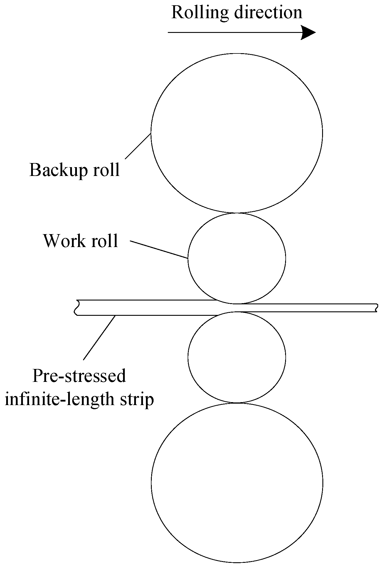
Strip steel is an important industrial raw material. With the development of modern industry, more and more attention has been paid to the accurate sizing of the strip [1,2,3]. As the core of size control, the hot rolling deformation model has been developed in which the influence of the incoming strip is naturally taken into account. In practical production, the aspect ratio (ratio of length to width) of the strip is very large during hot strip finishing rolling and the strip ends along the length direction can be regarded as an infinite region. Due to the uneven reduction and the transverse difference of temperature and microstructure, non-uniform stress is produced by the inhomogeneous longitudinal extension of each fiber along the strip width direction. With the restriction from the surrounding metal, the internal stress will not be released and remains in the strip until, finally, a pre-stressed strip will be formed and involved in the next rolling deformation, as shown in Figure 1. The plastic flow level of each fiber will not be identical under the non-uniform internal stress, which will finally influence the roll gap profile. Therefore, the effect of the internal stress of the incoming strip on hot rolling deformation should not be ignored. However, the existing models have paid more attention to the effect of the geometric dimensions of the incoming strip on the roll gap profile [4,5,6], and the effect of the internal stress of the incoming strip on hot rolling deformation is not fully emphasized, which results in a distorted result and limits the further improvement of the accuracy of the prediction model. Therefore, it is necessary to establish an effective rolling simulation model to study the effect of the internal stress of the incoming strip on hot rolling deformation.
Rolls-strip coupling models are widely used to simulate the rolling deformation. There are two main modelling methods: one establishes the rolls and strip deformation models, respectively, and builds up an iterative calculation between the two models according to the coordination relationship until the pre-set convergence condition is achieved [7,8]. The computing speed of this method is fast, but too many assumptions limit the accuracy of the calculation results. The other modelling method establishes the rolls-strip coupling model based on finite element analysis software, such as ABAQUS. The rolls are treated as elastic materials and the strip experiences elastic-plastic deformation. The two parts are linked by contact management to realize the coupling of the contact force and deformation [9,10,11,12]. This model can accurately describe the complex deformation of the strip under three-dimensional stress, and simultaneously output the transverse distribution of the roll force and roll gap profile. Thus, it is widely used for offline calculation of the strip gauge and profile.
In the traditional finite element rolling model, the strip is always defined as a short one for low computational cost. This is enough for the simulation of the rolling deformation of the strip without internal stress, but it will encounter the problem of how to apply the desired internal stress for the strip. In fact, the internal stress of the strip will be released at the beginning of rolling due to the free extension of the end metal. To avoid this problem, extending the strip is one available method. According to the Saint-Venant principle [13], if a large enough strip is truncated and the appropriate boundary conditions are imposed on the truncation ends, it can be approximately equal to the constraint effect of a nearly infinite domain. However, the disadvantages of this method are obvious: One is that the “large enough” truncated strip will bring a significant increase of the computational cost. The other is that the “appropriate boundary conditions” are difficult to determine.
The infinite element is proposed to make up the deficiency of the finite element in solving infinite domain problems, which is often introduced into the traditional finite element models. The finite element and infinite element (FE-IE) coupling model can not only consider the flexibility of the truncation boundary and the energy radiated into the infinite region, but also significantly eliminate the errors caused by inappropriate truncation and save the computational cost. Thus, it has already been widely used for “soil-structure interaction” analysis in earthquake engineering [14]. Yun et al. [15] developed dynamic infinite element formulations for soil-structure interaction analysis both in frequency and in time. The wave propagation characteristics in the far-field soil medium were represented. Zhang et al. [16] presented the coupling method of finite and infinite elements to simulate the propagating waves in a semi-infinite medium. The given examples indicated the feasibility of the model for analyzing the dynamic response of the foundation. Therefore, it is feasible to introduce the infinite element into the finite element rolling model to simulate the hot rolling deformation of nearly infinite-length strip with internal stress.
In this study, the improved rolls-strip coupling model based on the FE-IE coupling method is established. Several internal stresses with typical distribution forms are applied to the strip by a programmed user subroutine, which is used to evaluate the effect of the internal stress of the incoming strip on hot rolling deformation. The new model proposed is able to make up for the deficiency of the traditional finite element model and lay a theoretical foundation for further development of an accurate prediction model in the hot rolling process.
2. Coupling Principle of the Finite Element and Infinite Element
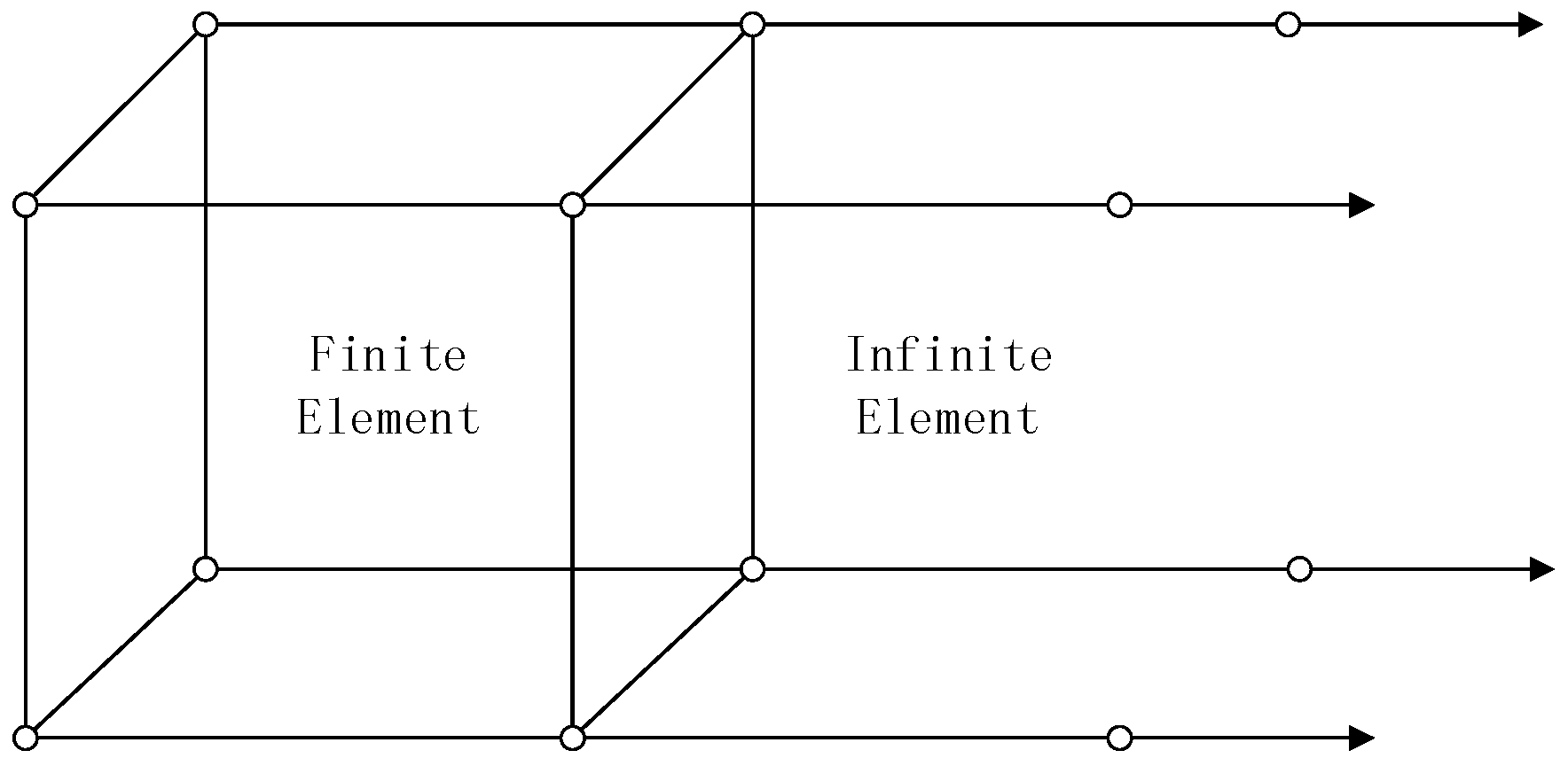
When solving infinite domain problems by the FE-IE coupling method, the research object is generally divided into two kinds of regions. The near-field region is modelled by the finite element, while the far-field region is modeled by the infinite element, as shown in Figure 2. Then, according to the equilibrium condition and consistency of the displacement on the interface between the finite element and infinite element, the displacement and stress of the nodes in the computation domain are calculated. The coupling calculation procedure is as follows:
- (1)
- Establish the equilibrium equations respectively for the near-field region and far-field region:where , are intermediate unknown variables; , are the interaction force between finite element and infinite element; and , are respectively the solution of the finite element region and infinite element region.
- (2)
- Obtain the displacement expression for finite element and infinite element on the interface:
- (3)
- Establish the continuous equations for the interface:
- (4)
- , are calculated by simultaneously solving the above equations, and then backward substituted to obtain the displacement and stress of the nodes.
3. Application of the Finite Element and Infinite Element (FE-IE) Coupling Method in Rolling Simulation
The FE-IE coupling model is established based on ABAQUS software (Dassault SIMULIA Company, version 6.13, Johnston, RI, USA). In the process of modelling, the complex internal stress is difficult to directly apply to the incoming strip in a dynamic explicit rolling model. In order to solve this problem, a static implicit stress field model is firstly established based on the FE-IE coupling method, and the programmed stress initialization subroutine SIGINI is adopted to realize the application of complex internal stress for the strip. Then the calculated stress field result is taken into the improved rolls-strip coupling model based on the FE-IE method to obtain the roll gap profiles under several internal stresses with typical distribution forms. The simulation technique route is shown in Figure 3.
3.1. Static Stress Field Model Based on FE-IE Coupling Method
In order to explain the advantage of the FE-IE coupling method in the rolling simulation, strips with different aspect ratios were established based on the static implicit analysis. Non-uniform internal stress was applied along the strip width by the programmed subroutine SIGINI at the initial time, of which the distribution function is shown as Equation (4). σ was the magnitude of the internal stress, MPa; B was the strip width, 1250 mm; and x was the position coordinate along the strip width direction. The stress results at a stable time were compared under different modelling methods and different aspect ratios to show the deficiency of the traditional FE method and the benefit of the FE-IE coupling method.
In the finite element models, “continuum, three-dimensional, eight-node linear brick, incompatible modes” element C3D8I (C means continuum, 3D means three-dimensional, 8 means eight-node linear brick, I means incompatible modes) and a hex mesh grid were adopted. The internal stress was applied to the strip by the programmed subroutine SIGINI. It can be seen from Figure 4a that the longitudinal stress in the whole strip is almost completely released in the case of a small aspect ratio (1:5). In the case of a medium aspect ratio (1:1), the longitudinal stress in nearly half of the strip is released and the amplitude of the remaining stress in the middle section decreases from 15 to about 8 MPa, as shown in Figure 5a. Until the strip is extended to large aspect ratio (5:1), most of the longitudinal stress is retained, except for the two ends, as shown in Figure 6a. It can be found that the traditional finite element model cannot realize the application of internal stress for the strip with a small aspect ratio. Although a long enough strip is able to simulate the elastic boundary of the surrounding metal and hold the internal stress, too long a strip means a significant increase in the computational cost. Therefore, it is necessary to find a highly efficient method to apply stable internal stress with a complex form to strips with a small aspect ratio.
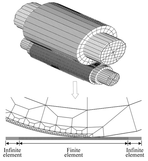
The FE-IE coupling method can be used to realize the accurate application of complex internal stress under any aspect ratio, especially under a small aspect ratio. The schematic diagram of the coupling method is shown in Figure 7. The strip was divided into a finite element region and an infinite element region. In the central finite element region, “3D, eight nodes, incompatible element” C3D8I and hex mesh grid were adopted. The strip was divided into four layers along the thickness direction and the mesh size along the length direction and width direction were, respectively, 2.5 mm and 4 mm. In the infinite element region at both strip ends, “3D, eight nodes, infinite element” CIN3D8 was adopted and a single-layer grid was meshed along the length direction. The internal stress was applied to the strip by the programmed subroutine SIGINI. The longitudinal stresses at stable time under different aspect ratios are shown in Figure 4b, Figure 5b and Figure 6b. It can be seen that the infinite element region is able to perfectly reflect the elastic boundary of the surrounding metal. The magnitude and distribution of the internal stress are unchanged. Therefore, the FE-IE coupling method can be used to realize the application of complex internal stress to the strip with a small aspect ratio.
3.2. Modified Rolls-Strip Coupling Model Based on FE-IE Coupling Method
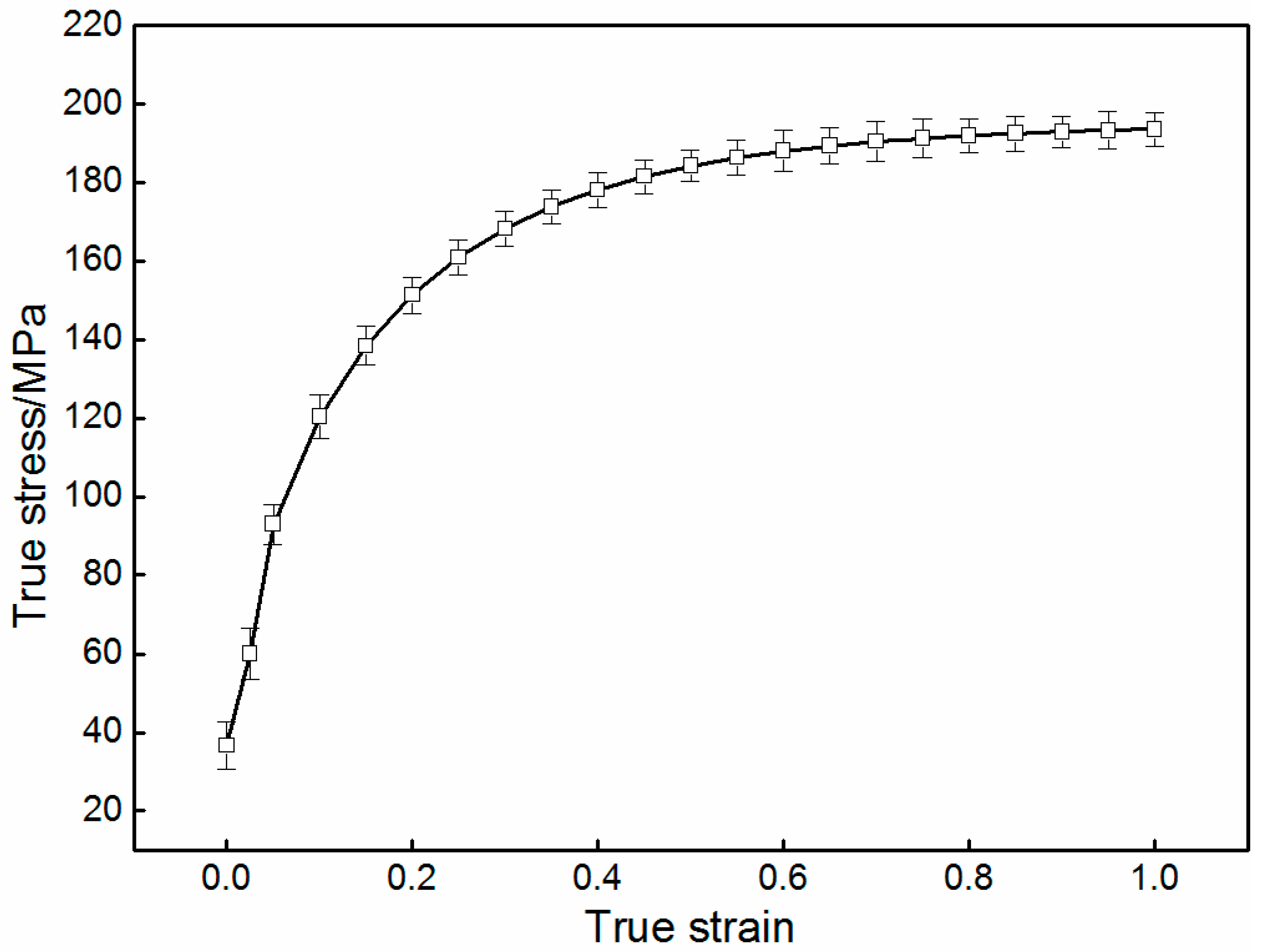
According to symmetry, the 1/2 improved rolls-strip coupling model was established based on the FE-IE coupling method, as shown in Figure 8. The analysis type was “dynamic, explicit”. The rollers were elastic, of which the element type was C3D8I. The strip was elastic-plastic, of which the geometrical dimensions, mesh size, element type, and modelling method were the same as for the previous static stress field model. The flow stress of the strip material was obtained by a thermal compression experiment, in which the test specimen was non-oriented electrical steel 50W800, the deformation temperature was 960 °C, and the strain rate was 10 s−1, which was close to the actual hot rolling production, as shown in Figure 9. Then the flow stress obtained was written into the elastic-plastic parameter table in the form of discrete points. The previous stress results calculated by the static stress field model were transferred to the strip. The contact surfaces of the backup rolls and work rolls, work rolls and strip were specially refined to improve the accuracy of the simulation results. The discrete rigid sheets were created and tied to the roller ends to simulate the rotation of the rollers. A smooth loading curve was adopted to make all the contacts steadily built. The main size and mechanical parameters of the rolling mill investigated are shown in Table 1.
3.3. Typical Distribution Forms of Internal Stress
The internal stress, which may be imposed stress or residual stress in the incoming strip, is not only related to the looper tension, but also dependent on the additional non-uniform stress caused by uneven reduction or thermal expansion before the current rolling. Therefore, the internal stress can be divided into two parts: One is the average stress, which is the mean value of the longitudinal stress of the fibers and is equal to the looper tension. The other is stress deviation (subtract the average stress from the longitudinal stress), which reflects the fluctuation of the longitudinal stress of each fiber around the average stress. The sum of stress deviations is zero to meet the self-balance. The typical distribution forms of the full-width internal stresses are as follows:
where σavg is the average stress, which is derived from setting the value of the looper tension, defined as 10 MPa; A is the amplitude of the stress deviation, defined as 5 MPa; B is the strip width; and k is the stress coefficient. k = 1 represents the quadratic wave stress, and k = 2 represents the quartic wave stress. Considering the similarity of the calculation results, only one case in “+” or “−” is chosen to be analyzed for the asymmetric stress. The magnitudes and distributions of typical internal stresses are shown in Figure 10.
4. Results and Discussion
4.1. Effect of Distribution Forms of Internal Stress on the Total Roll Force
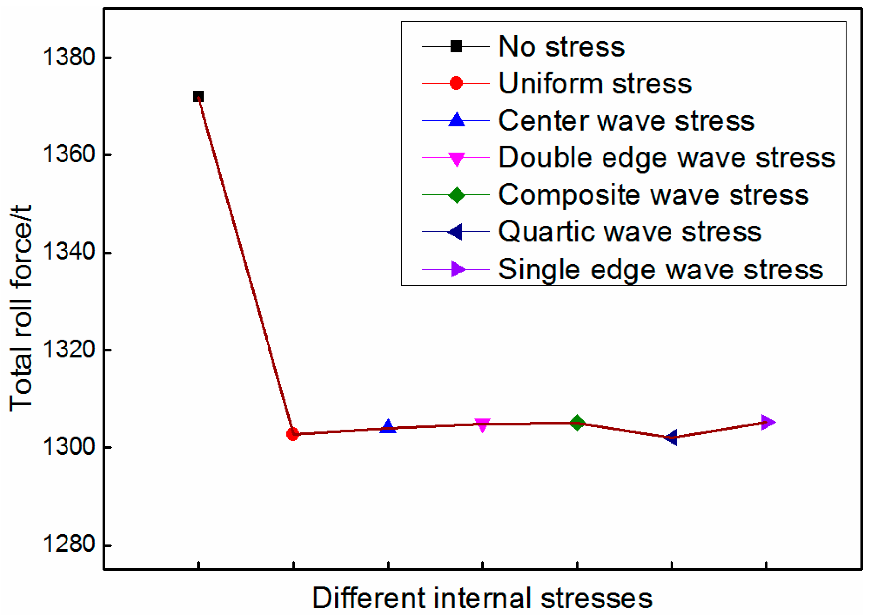
It can be seen from Figure 11 that the looper tension reduces the total roll force. As the distribution form of the internal stress varies, there is almost no change in the total roll force. This is because the sum of the stress deviation is zero. Under the average effect, the various distribution forms of internal stresses have little effect on the total roll force. Actually, the stress deviation only influences the extension of each fiber along the strip width direction, and further changes the distribution of the rolling force.
4.2. Effect of Uniform Stress on Roll Gap Profile
According to Equation (5), the uniform stress and no stress are respectively taken into the rolling model as the initial condition. It can be seen from Figure 12a that when uniform stress is applied to the strip, the central thickness and quadratic crown are decreased by 0.052 mm and 10 μm compared to the case of no stress. The reason is that tensile stress is helpful for metal flow along the rolling direction, and the longitudinal strain is enhanced along the whole width, as shown in Figure 12b, which results in the decrease of the roll force and central thickness. At the same time, the decrease of roll deflection makes the transverse thickness deviation decrease, and finally leads to the decrease of the quadratic crown.
4.3. Effect of Symmetric Stress on the Roll Gap Profile
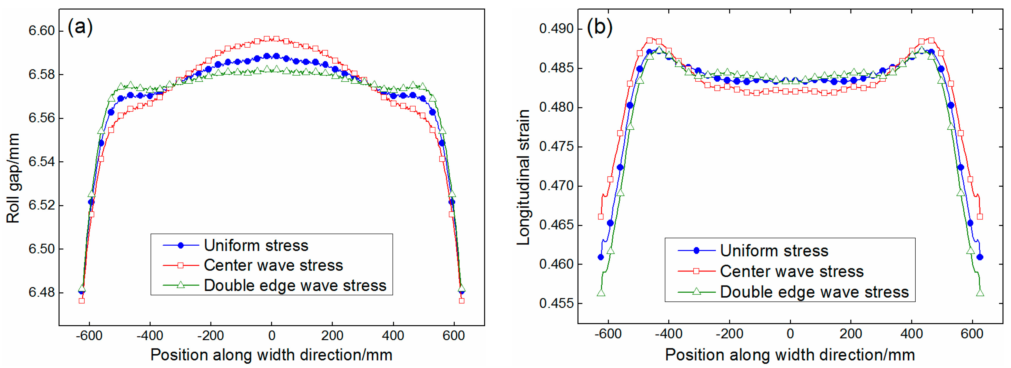
According to Equations (5) and (6), the uniform stress and the quadratic wave stress (including the middle wave stress and the double-edge wave stress) are respectively taken into the rolling model as the initial condition. It can be seen from Figure 13a that the roll gap profile is closely related to the magnitude and distribution of the stress deviation. When the double-edge wave stress is applied to the strip, the tensile stress of the central metal is greater than that of the edge. The metal in the middle is more likely to convert the reduction into a longitudinal plastic flow. Compared to the case of uniform stress, the central thickness of the strip is decreased by 0.006 mm. At the same time, the compression deformation of the edge metal becomes difficult and the longitudinal strain at the edge is suppressed, as shown in Figure 13b, which reduces the edge drop and makes the roll gap profile smooth, and the quadratic crown is decreased by 10 μm. Instead, when the middle wave stress is applied to the strip, the central thickness and quadratic crown are increased by 0.008 mm and 14 μm, respectively.
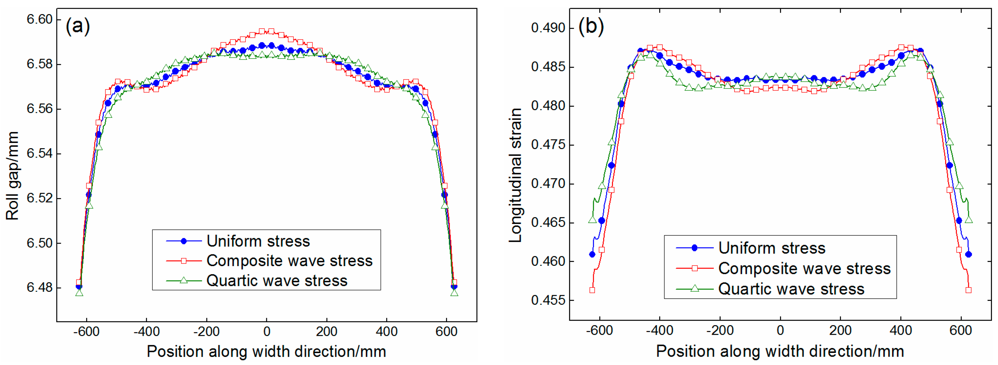
According to Equations (5) and (6), the uniform stress and the quartic wave stress (including the composite wave stress and the quarter wave stress) are respectively taken into the rolling model as the initial condition. It can be seen from Figure 14a that, compared to the case of uniform stress, the changes of the central thickness due to the composite wave stress and the quarter-wave stress are, respectively, 0.008 and −0.006 mm. These two kinds of quartic wave stress have little influence on the quadratic crown (respectively, 2 and 1 μm), but have a great effect on the quartic crown (respectively, 10 and −8 μm). It can also be seen from Figure 14b that the variation of longitudinal strain along the width direction is in accordance with the distribution form of the stress.
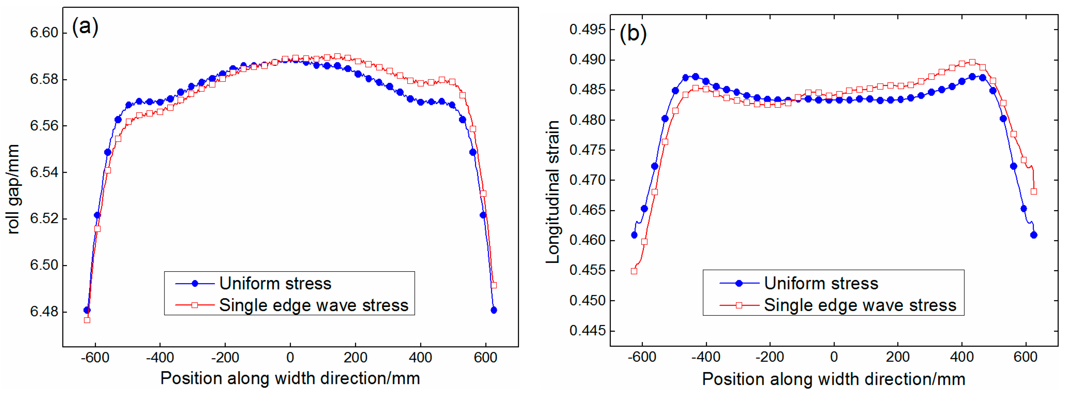
4.4. Effect of Asymmetric Stress on Roll Gap Profile
According to Equations (5) and (7), the uniform stress and the single-wave stress are respectively taken into the rolling model as the initial condition. It can be seen from Figure 15a that, because the stress values of the central fiber in the two cases are identical, the central thicknesses are the same. However, due to the asymmetry of the single-wave stress, the difficulty levels of metal flow on both sides are different, which leads to an obvious asymmetrical deformation. The thickness is smaller on the side with the larger tensile stress. Due to the average effect, this inclined deformation has little effect on the quadratic crown and quartic crown, but increases the wedge from 0 to 16 μm. At the same time, the longitudinal strain also appears asymmetrical, as shown in Figure 15b. The longitudinal strain on the tensile-stress side is greater than that on the compressive-stress side.
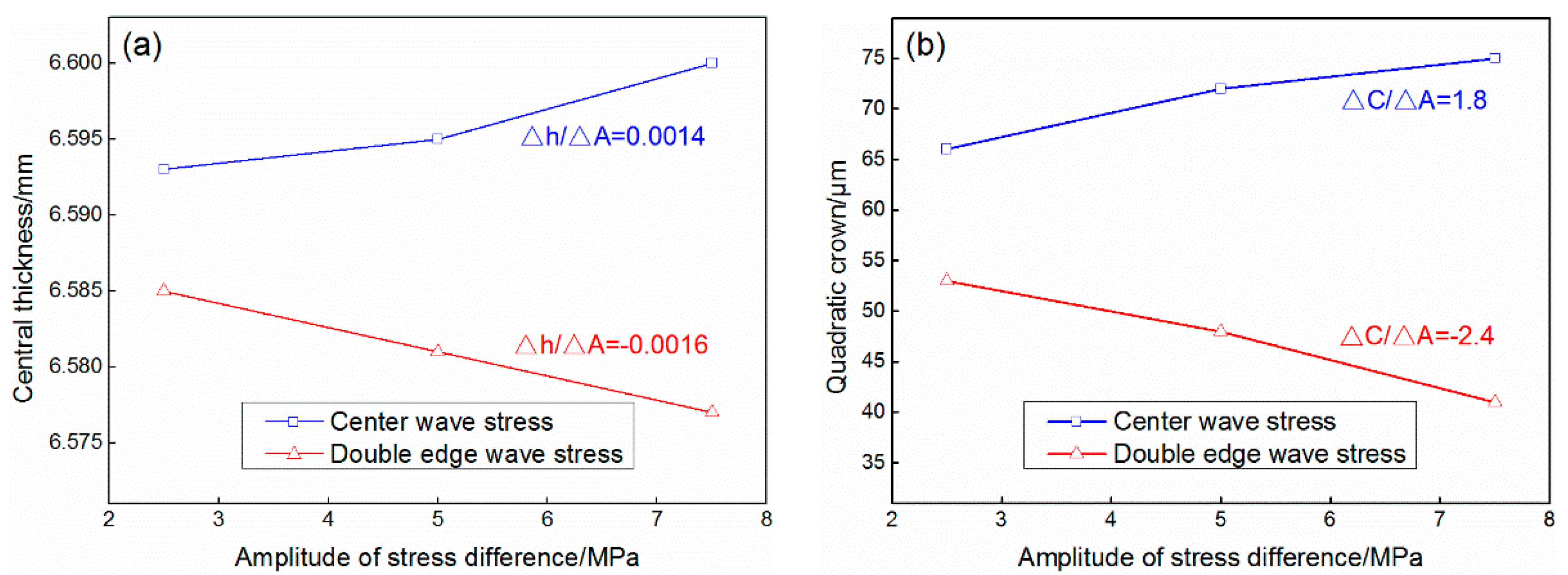
4.5. Efficacy Coefficients of Quadratic Wave Stress on the Central Thickness and Quadratic Crown
In order to quantify the effect of internal stress on the roll gap profile, for the most common quadratic wave stress, the roll gap profiles under different amplitudes of stress deviation are calculated to determine the efficacy coefficients of the quadratic wave stress on the central thickness and quadratic crown.
In detail, the amplitudes of stress deviation were selected as 2.5, 5, and 7.5 MPa, and respectively taken into the rolling model as the initial condition. The calculated results of the roll gap profiles corresponding to the middle wave stress and the double-edge wave stress are shown in Figure 16. The curves of the central thickness and quadratic crown varying with the amplitude of the stress deviation are shown in Figure 17. It can be seen from Figure 17a that when the middle wave stress is applied to the strip, the middle metal is subject to compressive stress compared to the edge. As the amplitude of stress deviation increases, the plastic flow of the middle metal becomes more and more difficult and the middle thickness is increased. The variation trend is almost linear and the efficacy coefficient of the middle wave stress on the central thickness is 0.0014 mm/MPa by fitting. Similarly, the efficacy coefficient of the double-edge wave stress on the central thickness is −0.0016 mm/MPa. It can be seen from Figure 17b that the variation trend of the quadratic crown varying with the amplitude of stress deviation is the same as the central thickness, and the efficacy coefficients of the middle wave stress and the double-edge wave stress on the quadratic crown are, respectively, 1.8 and −2.4 μm/MPa.
5. Conclusions
- (1)
- It is original to introduce the infinite element into the traditional finite element rolling model and this provides a new method to simulate the hot rolling deformation of a nearly infinite-length strip with complex internal stress.
- (2)
- Due to the average effect, the various distribution forms of the internal stress only change the distribution of the rolling force, but have little effect on the total roll force.
- (3)
- The strip profile is closely related to the distribution form of internal stress. Compared to the case of no stress, the central thickness and quadratic crown are decreased when uniform stress or double-edge wave stress is applied to the strip. The middle wave stress has an opposite effect on these two indicators. The quartic wave stress has little influence on the quadratic crown, but has a great effect on the quartic crown. The single-edge wave stress has little effect on the quadratic crown and the quartic crown, but increases the wedge.
- (4)
- The central thickness and quadratic crown of the strip vary almost linearly with the amplitude of the quadratic wave stress deviation, and the efficacy coefficients of the middle wave stress and the edge wave stress on the central thickness and quadratic crown are obtained, respectively.
Acknowledgments
The authors would like to thank the National Natural Science Foundation of China (no. 51674028 and no. 51404021) for the support to this research.
Author Contributions
Chao Liu did the simulation and wrote the paper. Anrui He, Yi Qiang and Jian Shao participated in the discussion on the results and guided the writing of the article. Defu Guo provided the test specimen.
Conflicts of Interest
The authors declare no conflict of interest.
References
- Li, H.J.; Xu, J.Z.; Wang, G.D.; Shi, L.J.; Xiao, Y. Development of strip flatness and crown control model for hot strip mills. J. Iron Steel Res. Int. 2010, 17, 21–27. [Google Scholar] [CrossRef]
- Kpogan, K.; Tampango, Y.; Zahrouni, H.; Potier-Ferry, M.; Ben-Dhia, H. Computing flatness defects in sheet rolling by Arlequin and Asymptotic numerical methods. Key Eng. Mater. 2014, 611, 186–193. [Google Scholar] [CrossRef]
- Fukushima, S.; Washikita, Y.; Sasaki, T.; Nakagawa, S.; Buei, Y.; Yakita, Y.; Yanagimoto, J. Mixed Scheduled Rolling of High Tensile Strength and Mild Steel Using a High-accuracy Profile Model in Hot Strip Finishing Mill. Tetsu Hagane 2014, 100, 1499–1507. [Google Scholar] [CrossRef]
- Xu, J.Z.; Gong, D.Y.; Zhang, W.C.; Chang, X.W.; Liu, X.H.; Wang, G.D. Model building of the initial crown effect rate in 4-high mill. J. Mater. Sci. Technol. 2005, 21, 165–169. [Google Scholar]
- Hu, Y.; Gong, D.Y.; Jiang, Z.Y.; Xu, J.Z.; Zhang, D.H.; Liu, X.H. Effect of initial crown on shape of hot rolled strip. J. Iron Steel Res. Int. 2009, 16, 32–34. [Google Scholar] [CrossRef]
- Aoh, J.N.; Hsu, H.K.; Dai, W.T.; Lin, C.Y.; Yeh, Y.L. Numerical simulation on correcting camber and wedge of steel slabs in hot rolling mill. Key Eng. Mater. 2014, 626, 570–575. [Google Scholar] [CrossRef]
- Abdelkhalek, S.; Montmitonnet, P.; Legrand, N.; Buessler, P. Coupled approach for flatness prediction in cold rolling of thin strip. Int. J. Mech. Sci. 2011, 53, 661–675. [Google Scholar] [CrossRef]
- Nakhoul, R.; Montmitonnet, P.; Legrand, N. Manifested flatness defect prediction in cold rolling of thin strips. Int. J. Mater. Form. 2015, 8, 283–292. [Google Scholar] [CrossRef] [Green Version]
- Wang, T.; Xiao, H.; Zhao, T.Y.; Qi, X.D. Improvement of 3-D FEM coupled model on strip crown in hot rolling. J. Iron Steel Res. Int. 2012, 19, 14–19. [Google Scholar] [CrossRef]
- Xu, H.B.; Ding, S.R.; Huo, Y.Z. Coupled thermo-mechanical FEM simulation of multi-pass vertical-horizontal rolling process. Adv. Mater. Res. 2014, 941, 1726–1734. [Google Scholar] [CrossRef]
- Jiang, Z.Y.; Hu, W.P.; Zhang, X.M.; Liu, X.H.; Wang, G.D. Coupled deformation and temperature analysis of strip rolling with a local perturbation of deformation using a 3D rigid-plastic FEM. Scand. J. Metall. 2004, 33, 29–38. [Google Scholar] [CrossRef]
- Jiang, Z.Y.; Xiong, S.W.; Tieu, A.K.; Wang, Q.J. Modeling of the effect of friction on cold strip rolling. J. Mater. Process. Technol. 2008, 201, 85–90. [Google Scholar] [CrossRef]
- Knops, P.J.; Payne, L.E. A Saint-Venant principle for nonlinear elasticity. Arch. Ration. Mech. Anal. 1983, 81, 1–12. [Google Scholar] [CrossRef]
- Seo, C.G.; Yun, C.B.; Kim, J.M. Three-dimensional frequency-dependent infinite elements for soil-structure interaction. Eng. Struct. 2007, 29, 3106–3120. [Google Scholar] [CrossRef]
- Yun, C.B.; Kim, D.B.; Kim, J.M. Analytical frequency-dependent infinite elements for soil-structure interaction analysis in two-dimensional medium. Eng. Struct. 2000, 22, 258–271. [Google Scholar] [CrossRef]
- Zhang, C.H.; Zhao, C.B. Coupling method of finite and infinite elements for strip foundation wave problems. Earthq. Eng. Struc. 1987, 15, 839–851. [Google Scholar]
Figure 1.
Schematic illustration of the rolling process of a pre-stressed infinite-length strip.

Figure 2.
Finite element and infinite element (FE-IE) coupling model.

Figure 3.
Simulation technique route.
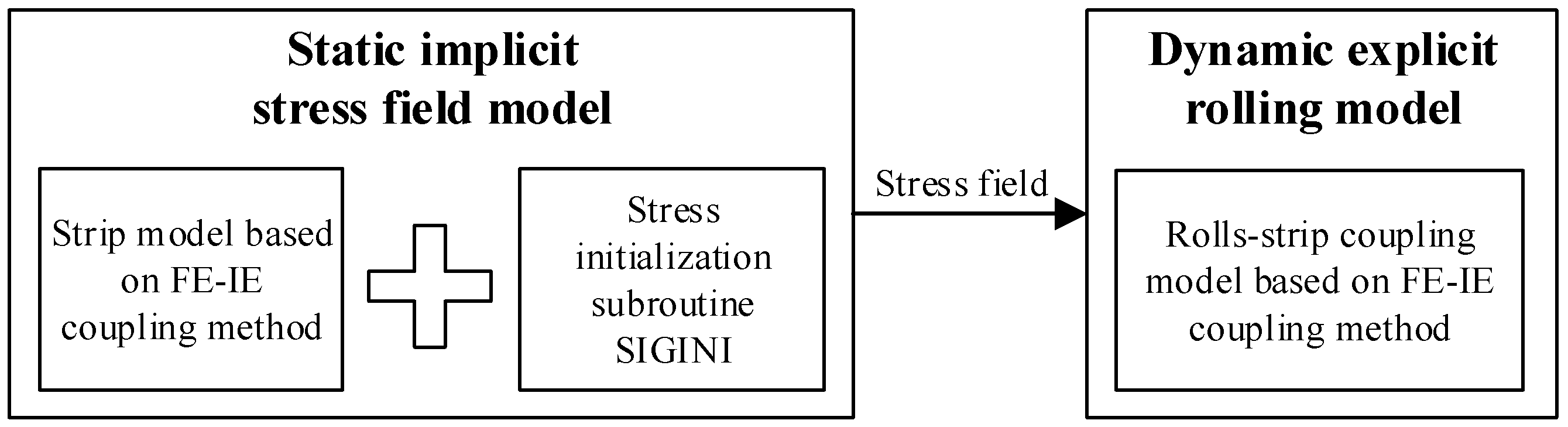
Figure 4.
Longitudinal stress at a stable time calculated by different methods under a small aspect ratio of 1:5: (a) finite element method (FEM); and (b) FE-IE coupling method.
Figure 4.
Longitudinal stress at a stable time calculated by different methods under a small aspect ratio of 1:5: (a) finite element method (FEM); and (b) FE-IE coupling method.
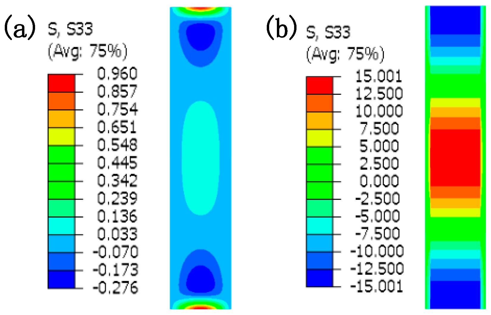
Figure 5.
Longitudinal stress at a stable time calculated by different methods under a medium aspect ratio of 1:1: (a) FEM; and (b) FE-IE coupling method.
Figure 5.
Longitudinal stress at a stable time calculated by different methods under a medium aspect ratio of 1:1: (a) FEM; and (b) FE-IE coupling method.
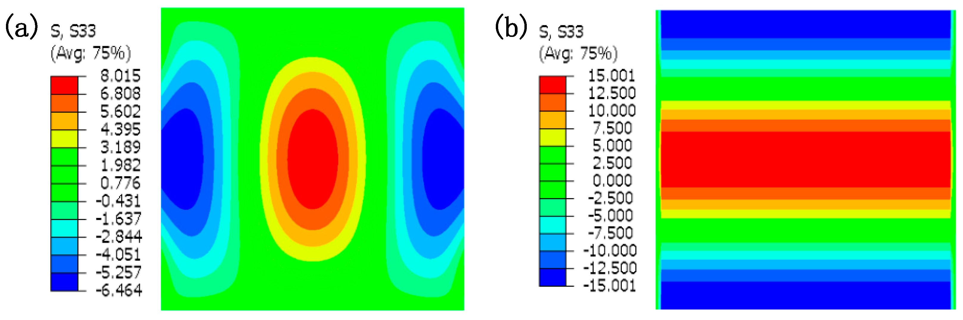
Figure 6.
Longitudinal stress at a stable time calculated by different methods under a large aspect ratio of 5:1: (a) FEM; and (b) FE-IE coupling method.
Figure 6.
Longitudinal stress at a stable time calculated by different methods under a large aspect ratio of 5:1: (a) FEM; and (b) FE-IE coupling method.
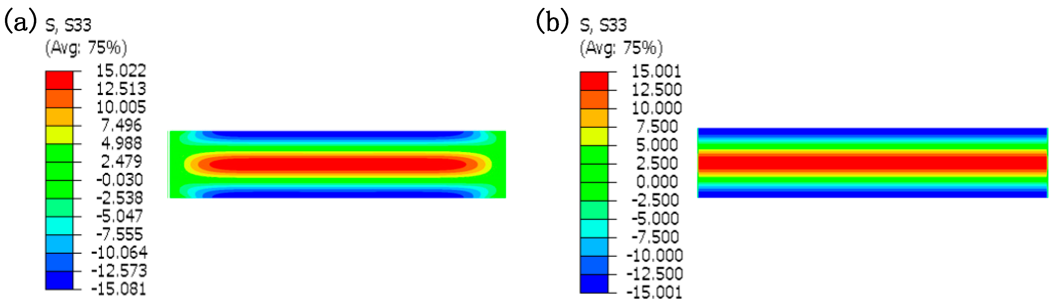
Figure 7.
Strip model based on FE-IE coupling method.
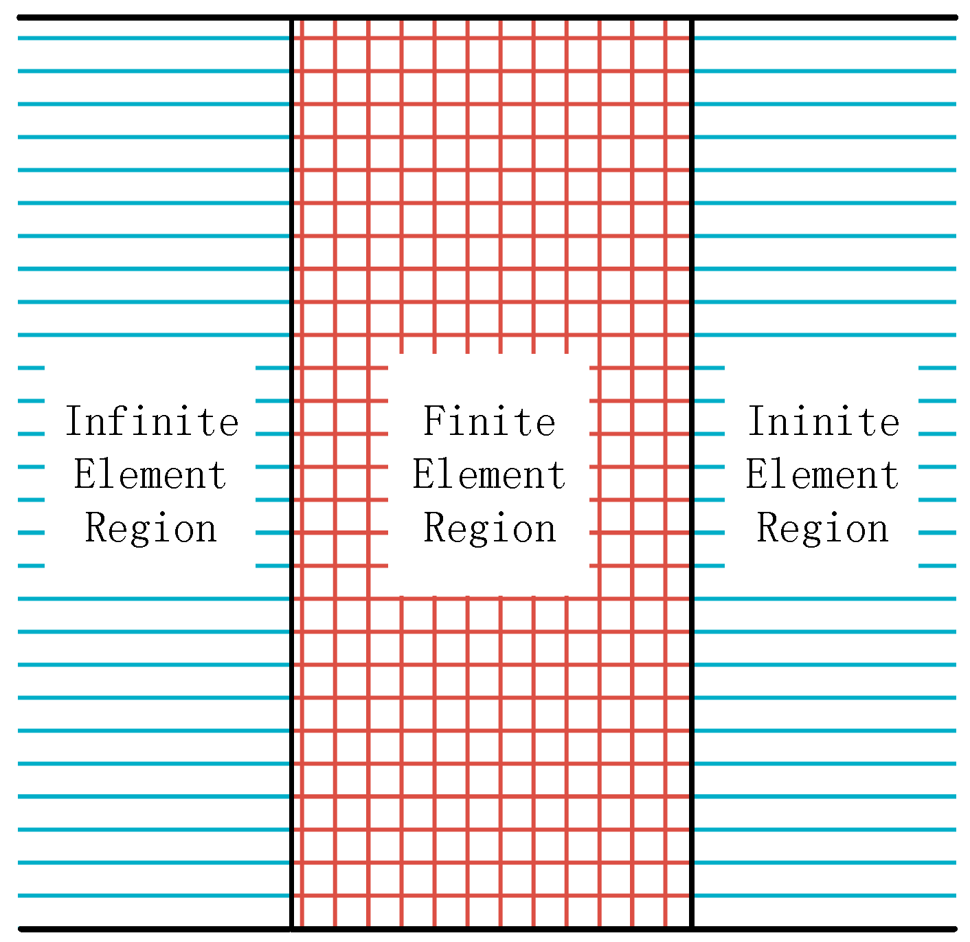
Figure 8.
Improved rolls-strip coupling model based on FE-IE coupling method.
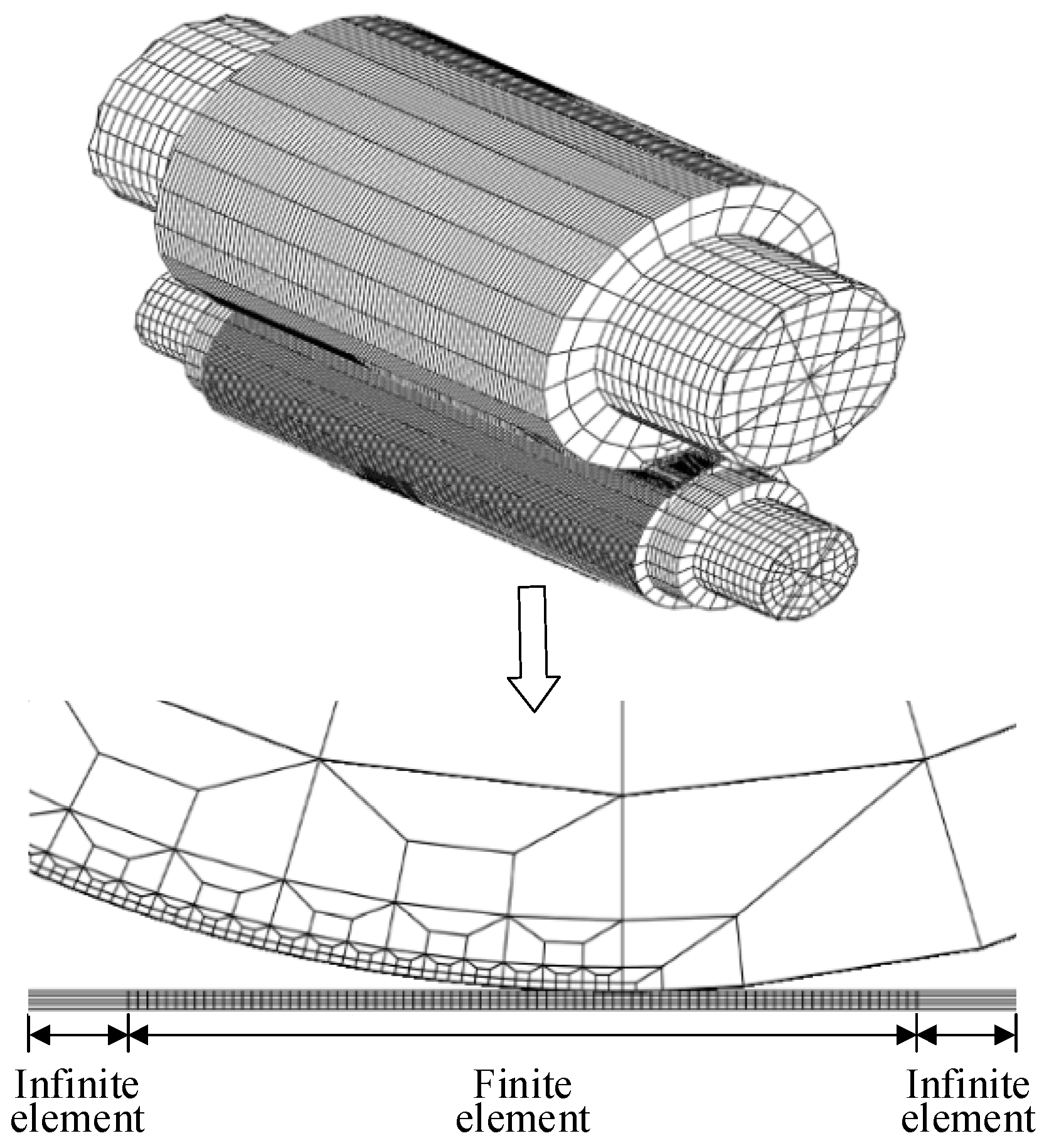
Figure 9.
Flow stress curve of the strip material.

Figure 10.
Magnitudes and distributions of typical internal stresses: (a) uniform stress; (b) middle wave stress; (c) double-edge wave stress; (d) composite wave stress; (e) quartic wave stress; and (f) single-edge wave stress.
Figure 10.
Magnitudes and distributions of typical internal stresses: (a) uniform stress; (b) middle wave stress; (c) double-edge wave stress; (d) composite wave stress; (e) quartic wave stress; and (f) single-edge wave stress.
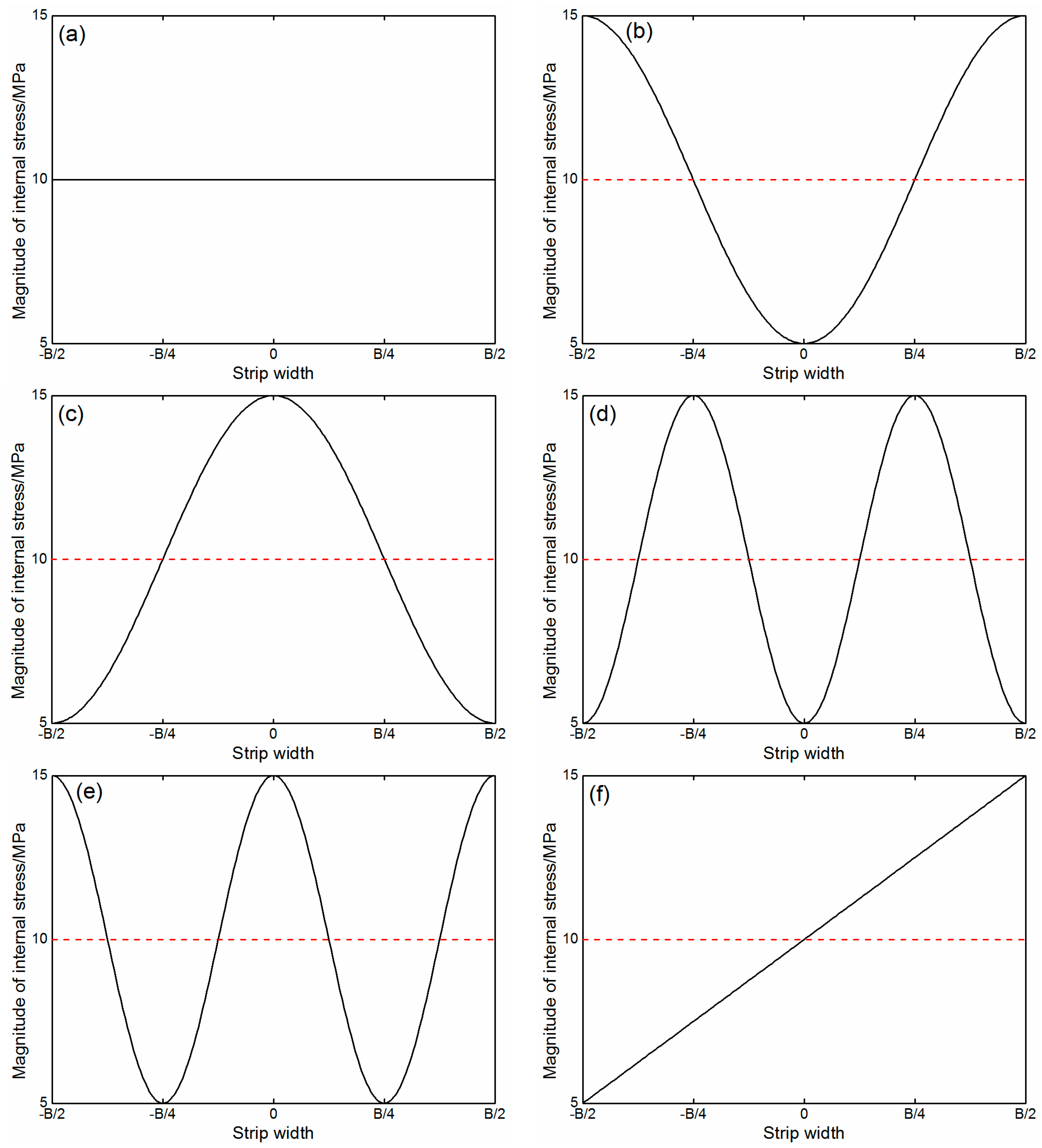
Figure 11.
Total roll force under internal stresses with various distribution forms.

Figure 12.
Effect of uniform stress on the roll gap profile and longitudinal strain: (a) effect on the roll gap profile; and (b) effect on the longitudinal strain.
Figure 12.
Effect of uniform stress on the roll gap profile and longitudinal strain: (a) effect on the roll gap profile; and (b) effect on the longitudinal strain.
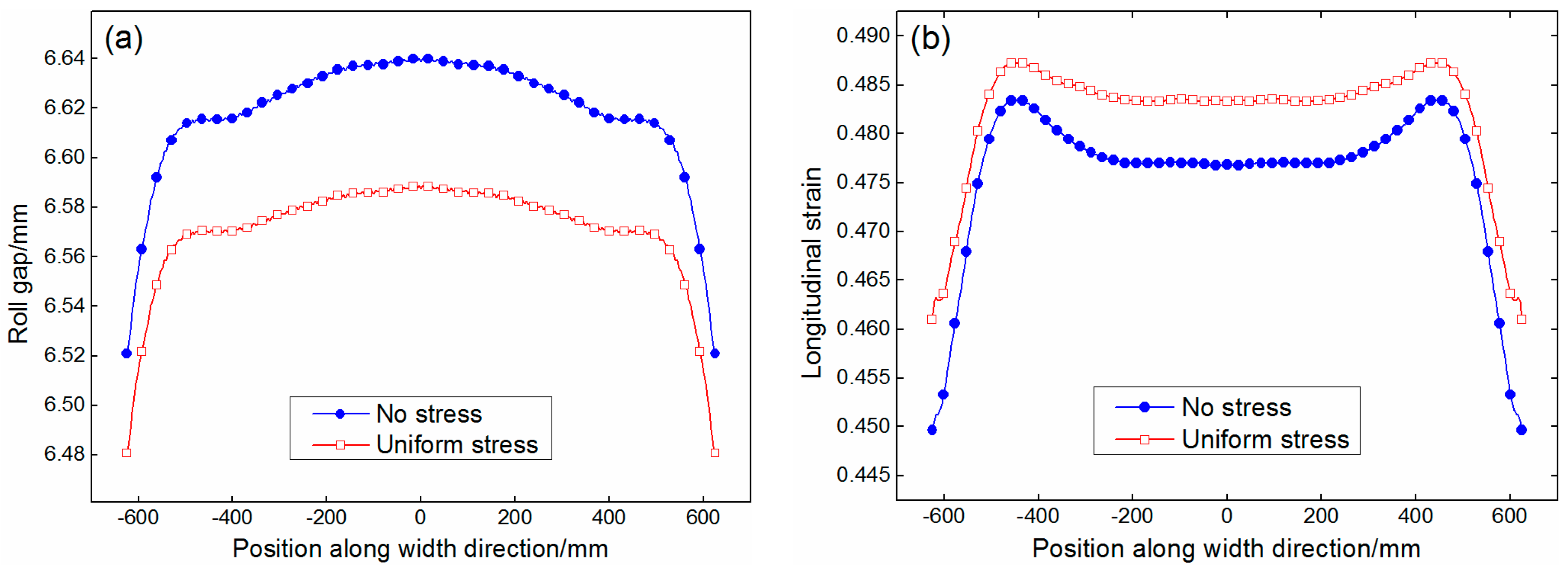
Figure 13.
Effect of quadratic wave stress on the roll gap profile and longitudinal strain: (a) effect on the roll gap profile; and (b) effect on the longitudinal strain.
Figure 13.
Effect of quadratic wave stress on the roll gap profile and longitudinal strain: (a) effect on the roll gap profile; and (b) effect on the longitudinal strain.

Figure 14.
Effect of quartic wave stress on the roll gap profile and longitudinal strain: (a) effect on the roll gap profile; and (b) effect on the longitudinal strain.
Figure 14.
Effect of quartic wave stress on the roll gap profile and longitudinal strain: (a) effect on the roll gap profile; and (b) effect on the longitudinal strain.

Figure 15.
Effect of asymmetric stress on the roll gap profile and longitudinal strain: (a) effect on the roll gap profile; and (b) effect on the longitudinal strain.
Figure 15.
Effect of asymmetric stress on the roll gap profile and longitudinal strain: (a) effect on the roll gap profile; and (b) effect on the longitudinal strain.

Figure 16.
Effect of quadratic wave stress on the roll gap profile under different amplitudes of stress deviation: (a) middle wave stress; and (b) double-edge wave stress.
Figure 16.
Effect of quadratic wave stress on the roll gap profile under different amplitudes of stress deviation: (a) middle wave stress; and (b) double-edge wave stress.
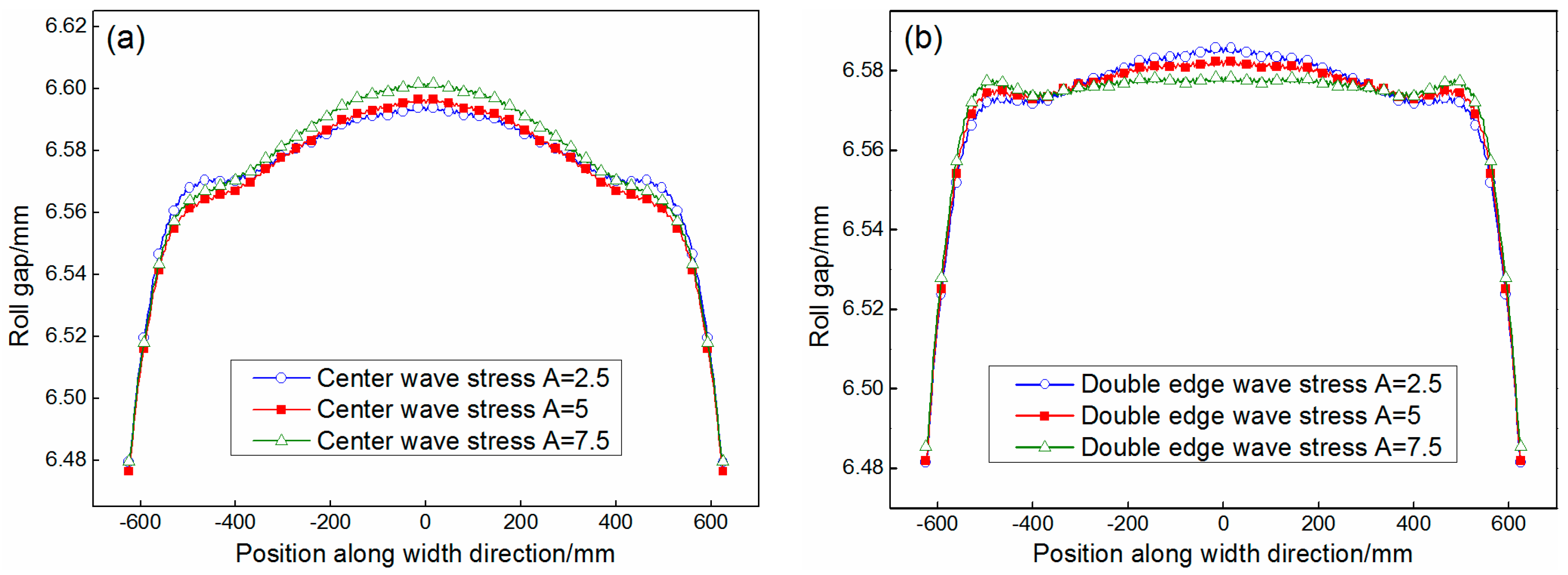
Figure 17.
Efficacy coefficient of quadratic wave stress on central thickness and quadratic crown: (a) efficacy coefficient on the central thickness; and (b) efficacy coefficient on the quadratic crown.
Figure 17.
Efficacy coefficient of quadratic wave stress on central thickness and quadratic crown: (a) efficacy coefficient on the central thickness; and (b) efficacy coefficient on the quadratic crown.


Table 1.
Size and mechanical parameters of the rolling mill investigated.
| Type of Mill | 4-High |
|---|---|
| Strip width/mm | 1250 |
| Entry strip thickness/mm | 10.66 |
| Exit strip thickness/mm | 6.6 |
| Body diameter of WR/BUR/mm | 730/1372 |
| Body length of WR/BUR/mm | 2000/1800 |
| Bending force/kN | 1200 |
| Looper tension/MPa | 8–12 |
| Friction coefficient between rolls | 0.1 |
| Friction coefficient between roll and strip | 0.1 |
© 2018 by the authors. Licensee MDPI, Basel, Switzerland. This article is an open access article distributed under the terms and conditions of the Creative Commons Attribution (CC BY) license (http://creativecommons.org/licenses/by/4.0/).
Share and Cite
MDPI and ACS Style
Liu, C.; He, A.; Qiang, Y.; Guo, D.; Shao, J. Effect of Internal Stress of Incoming Strip on Hot Rolling Deformation Based on Finite Element and Infinite Element Coupling Method. Metals 2018, 8, 92. https://doi.org/10.3390/met8020092
AMA Style
Liu C, He A, Qiang Y, Guo D, Shao J. Effect of Internal Stress of Incoming Strip on Hot Rolling Deformation Based on Finite Element and Infinite Element Coupling Method. Metals. 2018; 8(2):92. https://doi.org/10.3390/met8020092
Chicago/Turabian StyleLiu, Chao, Anrui He, Yi Qiang, Defu Guo, and Jian Shao. 2018. "Effect of Internal Stress of Incoming Strip on Hot Rolling Deformation Based on Finite Element and Infinite Element Coupling Method" Metals 8, no. 2: 92. https://doi.org/10.3390/met8020092
Note that from the first issue of 2016, this journal uses article numbers instead of page numbers. See further details here.