Preparation and Characterization of MoB Coating on Mo Substrate

1
School of Materials Science and Engineering, Hunan University of Science and Technology, Xiangtan 411201, China
2
Hunan Provincial Key Defense Laboratory of High Temperature Wear-Resisting Materials and Preparation Technology, Hunan University of Science and Technology, Xiangtan 411201, China
3
School of Materials Science and Engineering, Central South University, Changsha 410083, China
4
Key Laboratory of Ministry of Education for Non-ferrous Materials Science and Engineering, Central South University, Changsha 410083, China
5
Key Laboratory of Hunan Province for Metallurgy and Material Processing of Rare Metals, Central South University, Changsha 410083, China
*
Author to whom correspondence should be addressed.
Metals 2018, 8(2), 93; https://doi.org/10.3390/met8020093
Submission received: 30 December 2017
/
Revised: 19 January 2018
/
Accepted: 24 January 2018
/
Published: 26 January 2018
Abstract
:A molybdenum boride (MoB) coating was prepared on molybdenum (Mo) by an in-situ chemical vapor deposition method. To develop a fuller understanding of the effect of depositional conditions on the growth of MoB coating formed on Mo substrate, this paper studied the phase composition and microstructure of the coating at varied conditions. At the same time, the relationships between the growth of the coating in thickness and depositional conditions were also investigated. The phase composition of the coating, which was prepared using 0.2 wt % boron (B), was composed of MoB and Mo2B phases. The single MoB phase was obtained using a high B content (above 0.2 wt %). The microstructure of the coating showed that MoB coating could be prepared at temperatures over 900 °C. With the increase of temperature and time, the thickness of the coating increased. The growth of the coating was also influenced by the content of NaF. With increasing content, the thickness of the coating first increased, and then decreased. In addition, the prepared coating had a high hardness (3130.85 HV), and the mass change of the coated sample was only 4.92 mg/cm2 after isothermal oxidation at 600 °C for 100 h. The MoB coating could provide a good oxidation resistance for Mo at 600 °C.
1. Introduction
Boriding is a reliable surface hardening process which is widely used in industrial production to form a superhard wear-resistant surface. Boriding has been explored in the past by various ways, such as molten salt boriding [1], plasma-electrolysis boriding [2], and pack boriding [3]. The formation of boride coatings is influenced by the metal substrate, the boriding method, the composition of the boriding medium, the temperature, and the time of treatment.
Among boriding processes, halide-activated pack cementation (HAPC) is widely used because it is a low-cost, simple, and flexible process, allowing complex geometry components to be coated. HAPC is actually an in-situ chemical vapor deposition technique. In HAPC, the substrate is placed in a closed chamber, which is filled with a powder mixture called the pack, and then heated at a desired temperature in an inert atmosphere for a varied amount of time. The pack is composed of a master alloy or pure element powder, a halide salt activator, and an inert filler (such as Al2O3). Gaseous species of the element formed in the pack at high temperature are easily brought to the substrate surface, and the element is deposited on the surface of the substrate followed by a solid-state diffusion, which is considered as the rate-limiting step [4]. It is a diffusion coating process, so metallurgical bonding is formed between the coating and metal substrate. The composition and properties of the coating are sensitive to the process parameters, such as the pack composition, substrate composition, temperature, and time. Recent research shows that HAPC is mostly used for producing silicide-based coating on the surface of metals to improve their oxidation and corrosion resistance at elevated temperature [5,6,7,8,9]. In addition, to improve the life of the graphite substrate in an oxidizing environment, a SiC coating was prepared by HAPC [10]. Many studies have been done about boride coatings on steel [11,12,13,14], Ti [15,16], Nb [17], and W [18]. However, there are very few studies available about boride coatings on Mo prepared by HAPC. Akca et al. [19] studied the forming of boride on Mo by HAPC using the pack of composition 90SiC-5KBF4-5B4C (wt %), where the temperature (1000 °C, 1100 °C) and time (2–8 h) were investigated. In addition, electrochemical boriding of molybdenum was also studied [20]. The formed boride layers consisted of two distinct Mo2B4.027 and Mo2B5 phases. Although MoB coating on Mo prepared by HAPC was reported in our previous work [21,22], a more detailed study about MoB coating needs to be carried out. To develop a fuller understanding of the effect of depositional conditions on the growth of MoB coating formed on Mo substrate, in this work, the phase composition and microstructure of the coating at varied conditions were investigated, and the relationships between the growth of the coating in thickness and depositional conditions were revealed. At the same time, the hardness, elastic modulus, and low-temperature oxidation behavior of MoB coating were also studied.
2. Experimental
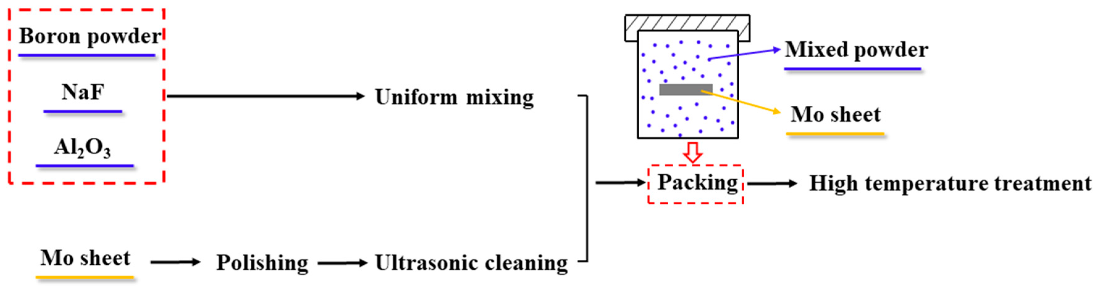
Mo sheets with the dimensions of Ø18 mm × 2 mm were used as the substrate for the coating experiments. A schematic diagram of the preparation of MoB coating on Mo is shown in Figure 1. All specimens were polished, ultrasonically cleaned, and dried. The coatings were applied on the above specimens by HAPC. The packs consisted of B (0.2–1.2 wt %), NaF (activator; 1–25 wt %), and Al2O3 (inter filler; balance). The as-prepared Mo specimens were embedded in Al2O3 crucibles, which were filled with the packs. The crucibles were then sealed with an alumina lid using alumina base cement. The cement sealing was dried at 60 °C for 12 h followed by controlled heating under argon flow. The temperature was gradually increased to the actual coating temperature (800–1050 °C) at a heating rate of 10 °C/min and held for a desired time (1–20 h). If only considering the heating and cooling stages, the holding time was designated as 0 h. After the end of each experiment, the as-coated specimens were washed in a water jet to remove any residual powder from the surface. Then, the specimens were ultrasonically cleaned and dried.
The microhardness and elastic modulus of MoB coating were measured at the polished cross-section of the coating by an Ultra Nanoindentation Tester (UNHT; CSM Anton Paar, Peseux, Switzerland) using a pyramidal indenter at room temperature (with a maximum load of 20 mN and a dwell time of 10 s). Five indentations were randomly done on the coating to get representative values of the microhardness and elastic modulus. The indentions were spaced sufficiently far apart so that the indention behavior was not affected by the adjacent indentations. The mean value was regarded as the microhardness and elastic modulus of the coating. The oxidation behavior of the coating at low temperature was evaluated by exposure oxidation at 600 °C for 100 h in air.
Scanning electron microscopy (SEM; FEI Quanta 2000, Hillsboro, OR, USA) was used for studying the cross-section microstructure of the coating. The thickness of the coating was estimated using image analysis on the backscattered electron (BSE) images of the cross-sectional microstructure of the coating. For each cross-section, 15 images were measured. The chemical composition analysis of the coating was carried out by an electron probe microanalyzer (EMPA; JEOL JXA-8230, Kyoto, Japan) with a wavelength-dispersive spectrometer (WDS; JEOL JXA-8230, Kyoto, Japan). The phase constitution of the coating was identified by X-ray diffraction (XRD; Rigaku D/max 2500, Kyoto, Japan) with Cu-Kα radiation under 40 kV and 250 mA.
3. Results and Discussion
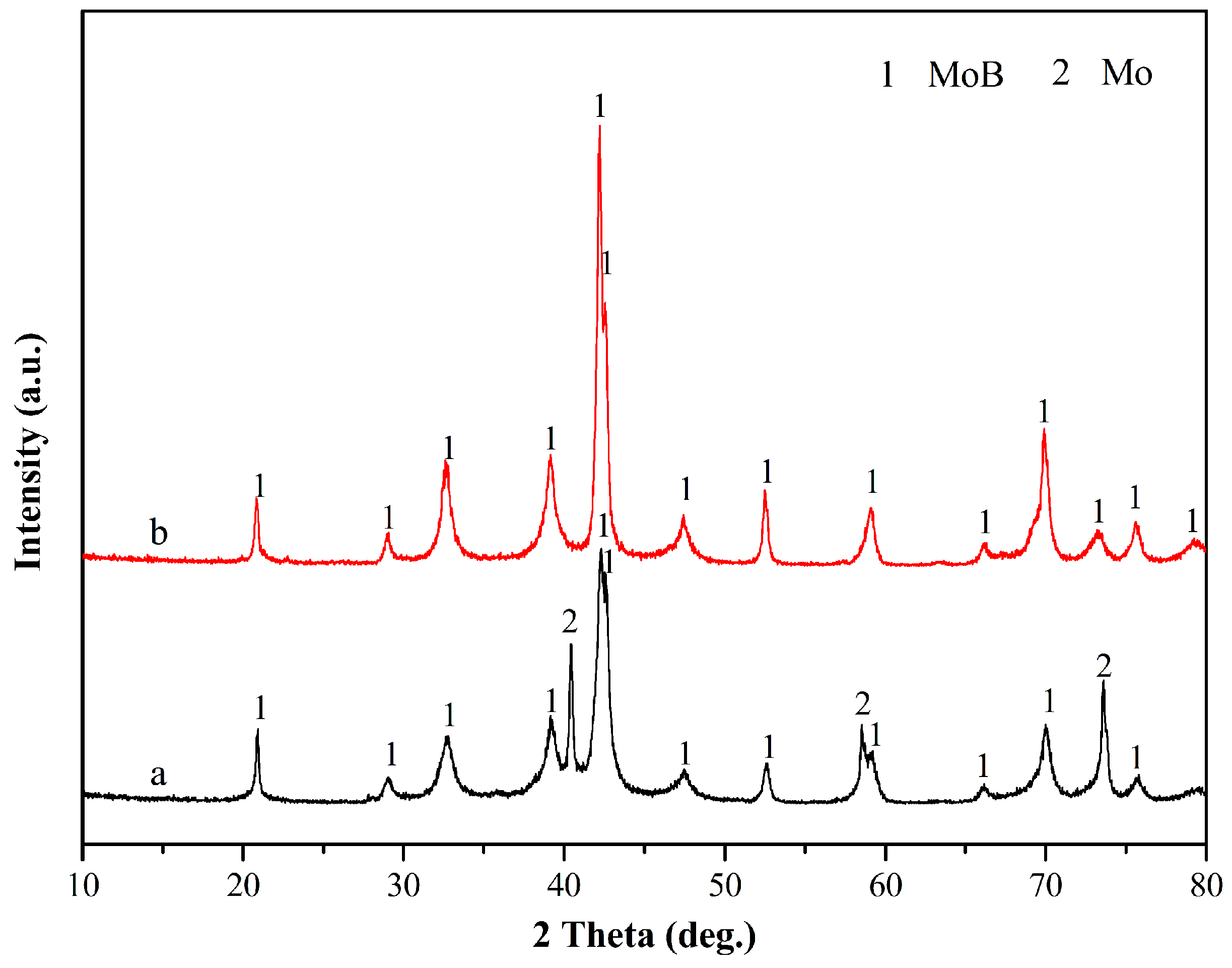
Figure 2 shows the surface XRD patterns of the MoB coatings prepared at 1000 °C with different time. As shown from the results of XRD analysis, the MoB coating was formed on Mo substrate due to B reacting with Mo during the HAPC. Moreover, the coating developed during the heating and cooling stages (Figure 2a). However, the thickness of the coating was very thin due to a very short duration of the reaction. Therefore, the composition of the substrate was detected by XRD.
The surface XRD patterns of the coated Mo prepared at different temperatures with 10 h are shown in Figure 3. The results of XRD analysis show only a small quantity of MoB formed on the surface of the substrate at 800 °C owing to a low diffusion rate of B or Mo at that temperature [23]. The diffusion of B would be increased at high temperatures (above 900 °C), resulting in an increase of the coating thickness, and only MoB phase was detected (Figure 3d). Consequently, a high temperature (above 900 °C) should be used for the preparation of MoB coating on Mo. The high temperature (above 900 °C) was also required to prepared Mo borides by solid-state reaction [24,25], mechanochemical synthesis [23], and electrochemical synthesis [26].
Figure 4 presents the surface XRD patterns of the borided Mo prepared with varied B content at 1000 °C for 5 h. The composition of the coating—which was prepared with 0.2 wt % B—consisted of MoB and Mo2B phases (Figure 4a). A small amount of B was deposited on the surface of the substrate during HAPC due to the low B content. The shortage of the B source resulted in the formation of a Mo2B phase. With the increase of the B content in the packs, a single phase-MoB coating formed on the Mo substrate as a result of sufficient B supply.
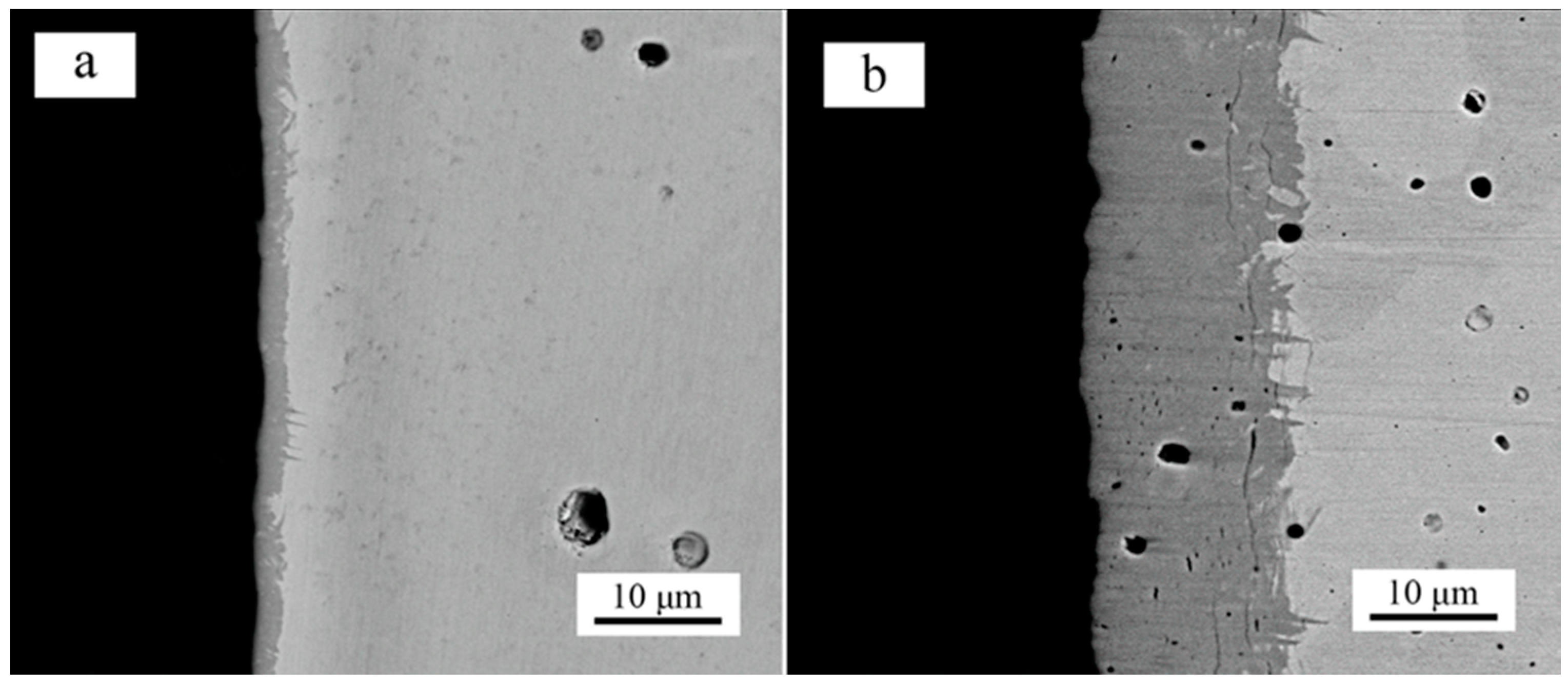
The backscattered electron (BSE) images of the cross-sectional microstructure of the MoB coating prepared at 1000 °C for 0 h and 5 h are shown in Figure 5. The coatings were composed of MoB phase (Figure 2). The thickness of the coating increased with prolonged holding time. Figure 6 shows the cross-sectional BSE images of the MoB coating prepared at different temperatures for 10 h. the coatings prepared at 800 °C and 850 °C were not observed (Figure 6a,b). However, a very thin MoB layer would be observed in the image with further magnification (an illustration in Figure 6b). Combined with the XRD results (Figure 3), MoB could be formed on the surface of Mo at 800 °C. However, the layer was not observed with further magnification. The poor diffusion of B at the low temperatures (below 900 °C) resulted in a slow growth of MoB. The diffusion of B increased with increasing temperature, which led to a fast growth of the MoB coating (Figure 6c–f).
The effect of the NaF content on the thickness of the coating was studied by varying the NaF content from 1 wt % to 25 wt % and keeping the B content at 0.8 wt %. The coating was prepared at 1000 °C for 10 h. The relationship between the thickness of the MoB coating and the NaF content in the packs is shown in Figure 7. With increasing the content of NaF, the thickness of the coating first increased and then decreased. More B was deposited on Mo with the increase of the NaF content (≤5 wt %), which led to an increase in the thickness of the coating. However, with the NaF content further increased (>5 wt %), a large number of B-containing gaseous fluorides were generated during the initial stage of reaction, which resulted in a steep increase in the crucible vapor pressure and the formation of cracks in the cement layer at the top of the crucible [27]. Most of the vapors would have exited the crucible. The quantities of the available B-containing gaseous fluorides, which are used for the growth of the coating, would have decreased. Therefore, the thickness of the coating decreased with increasing NaF content.
The effect of the holding time on the thickness of the coating was studied at a constant temperature (1000 °C) using a pack of composition 0.8B-5NaF-94.2Al2O3 (wt %). Figure 8 shows the relationship between the thickness of the coating and the holding time. The straight line in Figure 8 is a least-squares fit of the experimental data points, which follows Equation (1):
where h is the coating thickness (μm) and t is the time (h). A relatively low offset value of 0.70 was probably due to the fast heating and cooling rates. As shown from the result, with further increasing the holding time (>20 h), the growth of the coating in thickness slowed. This is because the growth of the coating is controlled by the solid-state diffusion of B, which is a rate-limiting step.
h = 7.11t1/2 + 0.70,
The relationship between the thickness of the MoB coating and the deposition temperature is presented in Figure 9. A pack of composition 0.8B-5NaF-94.2Al2O3 (wt %) was used for those experiments at the constant duration of 10 h. With increasing deposition temperature, the thickness of the coating increased. The solid-state diffusion process of B through the MoB coating from the surface to the interface of MoB/Mo is a rate-limiting step for the growth of the coating. The diffusion of B increased with increasing temperature, which led to the increase of the thickness of the coating. The B concentration in the coating was constant. As confirmed by XRD and EPMA, the composition of the coatings formed at all temperatures was identified as the MoB phase. Thus, the temperature only affected the thickness or the growth rate of the coating, not the B concentration in the coating. It was also observed that the effect of the temperature on the growth of the coating was more significant than that of time (t; h) because the diffusion of B was significantly influenced by the temperature—especially at higher temperatures. While keeping other conditions constant, the relationship between the coating thickness (h; μm) and the temperature (T; K) can be given according to Equation (2) [4].
where Ea (kJ/mol) is the activation energy of the coating growth process, R (J/(mol·K)) is a gas constant, and C0 is a constant. Figure 9 shows a good linear fit between ln(T1/2h) and 1/T (by the least-squares method) to the experimental data points. The activation energy obtained from the slope was 271.74 ± 32.41 kJ/mol. That is a qualitative value for the overall coating process.
ln(T1/2h) = −Ea/(RT) + C0,
The influence of the B content on the growth of the MoB coating was also studied at 1000 °C for 5 h using a 5 wt % NaF. The B content varied from 0.4 wt % to 1.2 wt %. Figure 10 shows the relationship between the coating thickness and the content of B. The thickness of the coating increased with increasing B content, but the composition of the coating did not change. Therefore, the variation of the B content in the packs did not influence the composition of the coating due to sufficient B supply during HAPC. The straight line in Figure 10 was drawn by a least-squares fit to data points [4], which gives:
where h (μm) is the coating thickness, and WB (wt %) is the content of B. The negative offset value could be due to the slower initiation of the coating process.
h = 26.17WB1/2 − 4.99,
The hardness and elastic modulus of the MoB coating are presented in Table 1. As shown in the table, the coating has a high hardness (3130.85 HV) and elastic modulus (519.31 GPa). Thus, the coating is usually used as a hardening layer or wear-resistant layer on the surface of metals in industry.
To study the oxidation behavior of the MoB coating at low temperature (600 °C), the coating was prepared at 1000 °C for 10 h using a pack composition of 0.8B-5NaF-94.2Al2O3 (wt %).
Figure 11 shows the mass change of the uncoated and coated Mo during isothermal oxidation. The results reveal that the oxidation rate of the coated Mo is lower than that of the uncoated Mo. Namely, much higher mass gain was observed for the uncoated Mo as compared to the Mo coated with MoB. The mass change of the Mo coated with MoB was only 4.92 mg/cm2 after isothermal oxidation at 600 °C for 100 h. However, the mass change of the uncoated Mo was up to 38.57 mg/cm2 after oxidation for 40 h. During the oxidation, the formation of B2O3—which has a good self-healing effect due to its melting flowing at the temperature [27]—could effectively inhibit oxidation. Thus, the MoB coating showed a relatively slow oxidation behavior. However, the formation of a loose MoO3—which can supply a diffusion path for O2—led to a rapid oxidation of the uncoated Mo. With increasing thickness of the oxide layer, the oxidation of the uncoated Mo was controlled by the diffusion of oxygen in the oxide layer. Thus, the uncoated Mo showed a parabolic oxidation (Figure 11). The oxidation behavior of the uncoated Mo was similar to the results reported by Kuznetsov et al. [28].
The relationships between the squared mass change per unit area of the samples (uncoated and coated Mo) and the oxidation time are presented in Figure 12. The oxidation rate constants were calculated from the slopes of the fitting straight lines in Figure 12, and listed in Table 2. The oxidation rate constants of the uncoated and coated Mo were 37.91 and 0.218 mg2/(cm4·h), respectively. This indicates that the MoB coating could provide a good oxidation resistance at 600 °C.
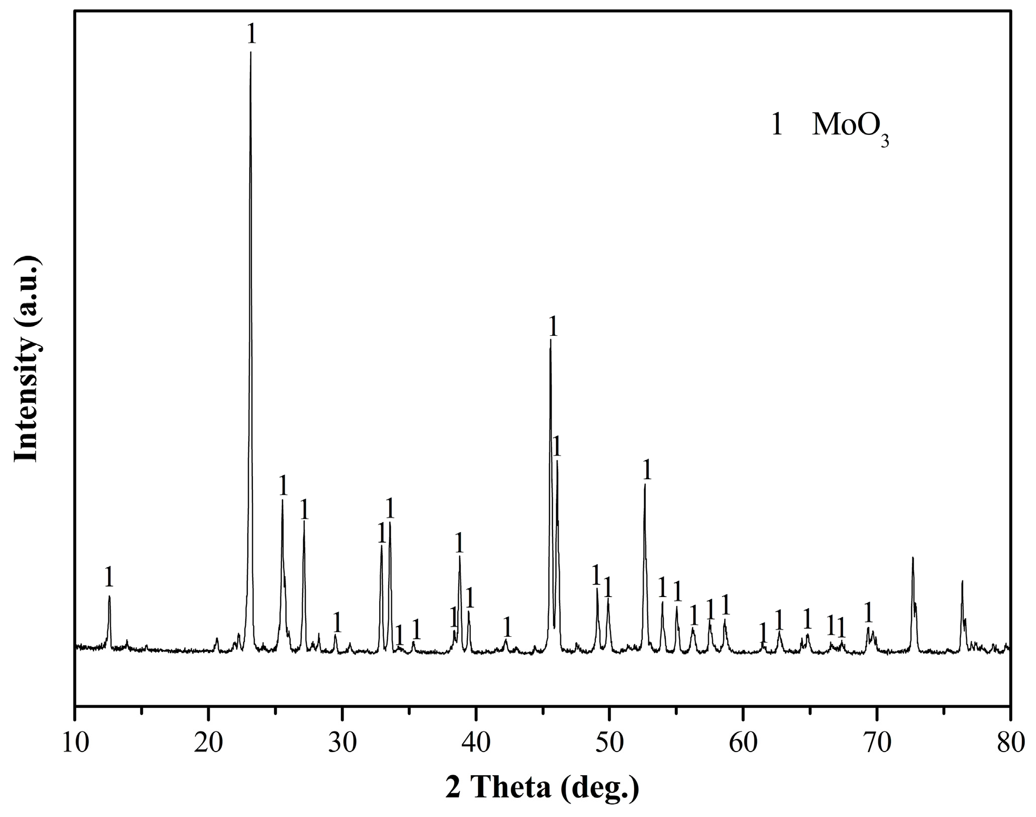
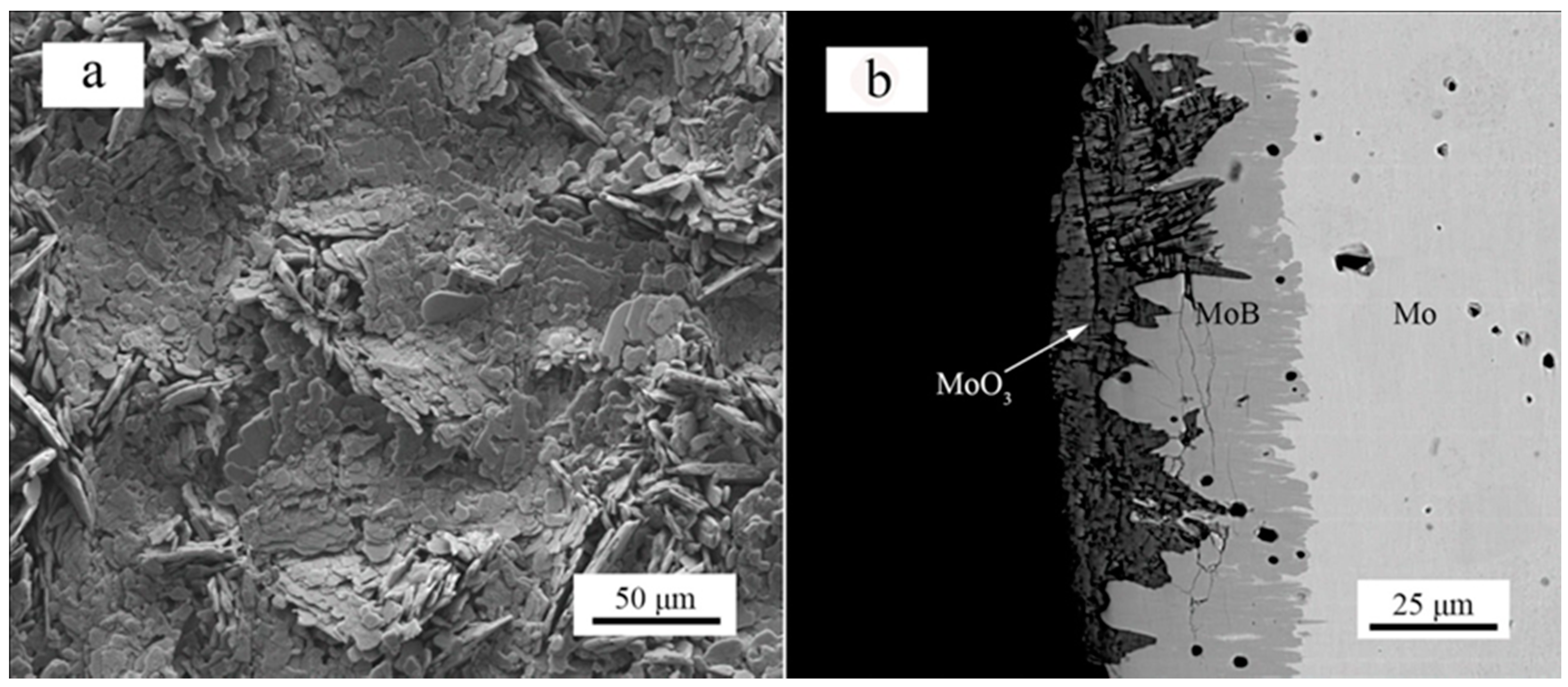
The surface XRD pattern of the coating after oxidation is shown in Figure 13. Only MoO3 phase was detected on the coating, probably due to a good melting flowing of B2O3 at 600 °C. The surface and cross-sectional images of the MoB coating after oxidation are shown in Figure 14. Scale-like MoO3 formed on the surface of the coating (Figure 14a). The coating was mainly composed of MoO3 and MoB (Figure 14b).
4. Conclusions
MoB coating was successfully prepared on Mo by a pack cementation process. The single MoB phase could be obtained using a high B content (above 0.2 wt %). MoB coating could be prepared at temperatures over 900 °C. The thickness of MoB coating first increased first and then decreased with increasing content of NaF. With the increase of the temperature and time, the thickness of MoB coating increased. The effect of the temperature on the thickness was more significant than that of the time because the temperature could significantly improve the diffusion of B. The growth of the coating in thickness also increased with increasing B content in the pack. The as-prepared MoB coating had a high hardness (3130.85 HV) and elastic modulus (519.31 GPa). The weight gain of the MoB-coated Mo was only 4.92 mg/cm2 after isothermal oxidation at 600 °C for 100 h. MoB coating could improve the oxidation resistance of Mo at 600 °C.
Acknowledgments
This work was supported by National Nature Science Foundation of China (51475161), the Research Foundation of Education Bureau of Hunan Province (15A059), Scientific Research Fund of Hunan Provincial Education Department (17C0622), and Scientific Research Project of Hunan University of Science and Technology (E51511). The work is also supported by State Key Laboratory of Powder Metallurgy of Central South University. We also thank the Key Laboratory of Non-ferrous Materials Science and Engineering (Central South University), Ministry of Education, for research facilities.
Author Contributions
Yi Wang and Haiyan Shi conceived and designed the experiments; Yi Wang and Haiyan Shi prepared the coating samples and performed the oxidation test; Yi Wang performed the XRD measurements; Jianhui Yan performed SEM measurements; Yi Wang and Dezhi Wang wrote the paper.
Conflicts of Interest
The authors declare no conflict of interest.
References
- Ma, L.S.; Duan, Y.H.; Li, P. Microstructure, growth kinetics and some mechanical properties of boride layers produced on pure titanium by molten-salt boriding. J. Mater. Eng. Perform. 2017, 26, 4544–4555. [Google Scholar] [CrossRef]
- Béjar, M.A.; Henríquez, R. Surface hardening of steel by plasma-electrolysis boronizing. Mater. Des. 2009, 30, 1726–1728. [Google Scholar] [CrossRef]
- Aytekin, H.; Akçin, Y. Characterization of borided Incoloy 825 alloy. Mater. Des. 2013, 50, 515–521. [Google Scholar] [CrossRef]
- Majumdar, S.; Sharma, I.; Samajdar, I.; Bhargava, P. Relationship between pack chemistry and growth of silicide coatings on Mo-TZM alloy. J. Electrochem. Soc. 2008, 155, D734–D741. [Google Scholar] [CrossRef]
- Chaia, N.; Portebois, L.; Mathieu, S.; David, N.; Vilasi, M. On the interdiffusion in multilayered silicide coatings for the vanadium-based alloy V-4Cr-4Ti. J. Nucl. Mater. 2017, 484, 148–156. [Google Scholar] [CrossRef]
- Sun, J.; Fu, Q.G.; Guo, L.P.; Wang, L. Silicide coating fabricated by HAPC/SAPS Combination to protect niobium alloy from oxidation. ACS Appl. Mater. Interfaces 2016, 8, 15838–15847. [Google Scholar] [CrossRef] [PubMed]
- Tian, X.D.; Guo, X.P.; Sun, Z.P.; Qu, J.L.; Wang, L.J. Oxidation resistance comparison of MoSi2 and B-modified MoSi2 coatings on pure Mo prepared through pack cementation. Mater. Corros. 2015, 66, 681–687. [Google Scholar] [CrossRef]
- Cheng, J.; Yi, S.; Park, J.S. Simultaneous coating of Si and B on Nb–Si–B alloys by a halide activated pack cementation method and oxidation behaviors of the alloys with coatings at 1100 °C. J. Alloys Compd. 2015, 644, 975–981. [Google Scholar] [CrossRef]
- Tian, X.; Guo, X.; Sun, Z.; Yin, Z.; Wang, L. Formation of B-modified MoSi2 coating on pure Mo prepared through HAPC process. Int. J. Refract. Met. Hard Mater. 2014, 45, 8–14. [Google Scholar] [CrossRef]
- Paul, B.; Prakash, J.; Sarkar, P.S. Formation and characterization of uniform SiC coating on 3-D graphite substrate using halide activated pack cementation method. Surf. Coat. Technol. 2015, 282, 61–67. [Google Scholar] [CrossRef]
- Wei, X.; Chen, Z.; Zhong, J.; Wang, L.; Hou, Z.; Zhang, Y.; Tan, F. Facile preparation of nanocrystalline Fe2B coating by direct electro-spark deposition of coarse-grained Fe2B electrode material. J. Alloys Compd. 2017, 717, 31–40. [Google Scholar] [CrossRef]
- Xie, F.; Wang, X.J.; Pan, J.W. Accelerate pack boriding with reused boriding media by simultaneously employing Al and alternating current field. Vacuum 2017, 141, 166–169. [Google Scholar] [CrossRef]
- Balokhonov, R.R.; Romanova, V.A.; Schmauder, S.; Martynov, S.A.; Kovalevskaya, Z.G. A mesomechanical analysis of plastic strain and fracture localization in a material with a bilayer coating. Compos. Part B Eng. 2014, 66, 276–286. [Google Scholar] [CrossRef]
- Márquez-Herrera, A.; Fernandez-Muñoz, J.L.; Zapata-Torres, M.; Melendez-Lira, M.; Cruz-Alcantar, P. Fe2B coating on ASTM A-36 steel surfaces and its evaluation of hardness and corrosion resistance. Surf. Coat. Technol. 2014, 254, 433–439. [Google Scholar] [CrossRef]
- Tsipas, S.A.; Vázquez-Alcázar, M.R.; Navas, E.M.R.; Gordo, E. Boride coatings obtained by pack cementation deposited on powder metallurgy and wrought Ti and Ti–6Al–4V. Surf. Coat. Technol. 2010, 205, 2340–2347. [Google Scholar] [CrossRef]
- Sarma, B.; Tikekar, N.M.; Ravi Chandran, K.S. Kinetics of growth of superhard boride layers during solid state diffusion of boron into titanium. Ceram. Int. 2012, 38, 6795–6805. [Google Scholar] [CrossRef]
- Dokumaci, E.; Özkan, I.; Özyigit, M.B.; Önay, B. Effect of boronizing on the oxidation of niobium. Int. J. Refract. Met. Hard Mater. 2013, 41, 276–281. [Google Scholar] [CrossRef]
- Ingole, S.; Liang, H.; Usta, M.; Bindal, C.; Ucisik, A.H. Multi-scale wear of a boride coating on tungsten. Wear 2005, 259, 849–860. [Google Scholar] [CrossRef]
- Akca, B.; Calik, A. Characterization of borided pure molybdenum under controlled atmosphere. Prot. Met. Phys. Chem. 2017, 53, 511–517. [Google Scholar] [CrossRef]
- Feridun, O.K.; Sista, V.; Eryilmaz, O.L.; Erdemir, A. Electrochemical boriding of molybdenum in molten borax. Surf. Eng. 2015, 31, 575–580. [Google Scholar] [CrossRef]
- Wang, Y.; Wang, D.; Yan, J. Preparation and characterization of MoSi2/MoB composite coating on Mo substrate. J. Alloys Compd. 2014, 589, 384–388. [Google Scholar] [CrossRef]
- Wang, Y.; Yan, J.; Wang, D. High temperature oxidation and microstructure of MoSi2/MoB composite coating for Mo substrate. Int. J. Refract. Met. Hard Mater. 2017, 68, 60–64. [Google Scholar] [CrossRef]
- Çamurlu, H.E. Preparation of single phase molybdenum boride. J. Alloys Compd. 2011, 509, 5431–5436. [Google Scholar] [CrossRef]
- Yeh, C.L.; Hsu, W.S. Preparation of MoB and MoB–MoSi2 composites by combustion synthesis in SHS mode. J. Alloys Compd. 2007, 440, 193–198. [Google Scholar] [CrossRef]
- Yeh, C.L.; Hsu, W.S. Preparation of molybdenum borides by combustion synthesis involving solid-phase displacement reactions. J. Alloys Compd. 2008, 457, 191–197. [Google Scholar] [CrossRef]
- Kuznetsov, S.A.; Rebrov, E.V.; Mies, M.J.M.; de Croon, M.H.J.M.; Schouten, J.C. Synthesis of protective Mo-Si-B coatings in molten salts and their oxidation behavior in an air-water mixture. Surf. Coat. Technol. 2006, 201, 971–978. [Google Scholar] [CrossRef]
- Wu, J.; Wang, W.; Zhou, C. Microstructure and oxidation resistance of Mo–Si–B coating on Nb based in situ composites. Corros. Sci. 2014, 87, 421–426. [Google Scholar] [CrossRef]
- Kuznetsov, S.A.; Kuznetsova, S.V.; Rebrov, E.V.; Mies, M.J.M.; de Croon, M.H.J.M.; Schouten, J.C. Synthesis of molybdenum borides and molybdenum silicides in molten salts and their oxidation behavior in an air-water mixture. Surf. Coat. Technol. 2005, 195, 182–188. [Google Scholar] [CrossRef]
Figure 1.
Schematic diagram of the preparation of MoB coating on Mo.

Figure 2.
The surface XRD patterns of the MoB coating prepared at 1000 °C with varying time. (a) 0 h; (b) 5 h.
Figure 2.
The surface XRD patterns of the MoB coating prepared at 1000 °C with varying time. (a) 0 h; (b) 5 h.

Figure 3.
The surface XRD patterns of the coated Mo prepared at different temperatures for 10 h. (a) 800 °C; (b) 850 °C; (c) 900 °C; (d) 950 °C; (e) 1050 °C.
Figure 3.
The surface XRD patterns of the coated Mo prepared at different temperatures for 10 h. (a) 800 °C; (b) 850 °C; (c) 900 °C; (d) 950 °C; (e) 1050 °C.
Figure 4.
The surface XRD patterns of the borided Mo prepared with varied B content at 1000 °C for 5 h. (a) 0.2 wt %; (b) 0.4 wt %; (c) 0.6 wt %; (d) 1.0 wt %; (e) 1.2 wt %.
Figure 4.
The surface XRD patterns of the borided Mo prepared with varied B content at 1000 °C for 5 h. (a) 0.2 wt %; (b) 0.4 wt %; (c) 0.6 wt %; (d) 1.0 wt %; (e) 1.2 wt %.
Figure 5.
Backscattered electron (BSE) images of the cross-sectional microstructure of MoB coating prepared at 1000 °C for (a) 0 h and (b) 5 h.
Figure 5.
Backscattered electron (BSE) images of the cross-sectional microstructure of MoB coating prepared at 1000 °C for (a) 0 h and (b) 5 h.

Figure 6.
The cross-sectional BSE images of the MoB coating on Mo prepared at varied temperatures for 10 h. (a) 800 °C; (b) 850 °C; (c) 900 °C; (d) 950 °C; (e) 1000 °C; (f) 1050 °C.
Figure 6.
The cross-sectional BSE images of the MoB coating on Mo prepared at varied temperatures for 10 h. (a) 800 °C; (b) 850 °C; (c) 900 °C; (d) 950 °C; (e) 1000 °C; (f) 1050 °C.
Figure 7.
The relationship between the thickness of the MoB coating and the NaF content in the packs (the red: error bars).
Figure 7.
The relationship between the thickness of the MoB coating and the NaF content in the packs (the red: error bars).
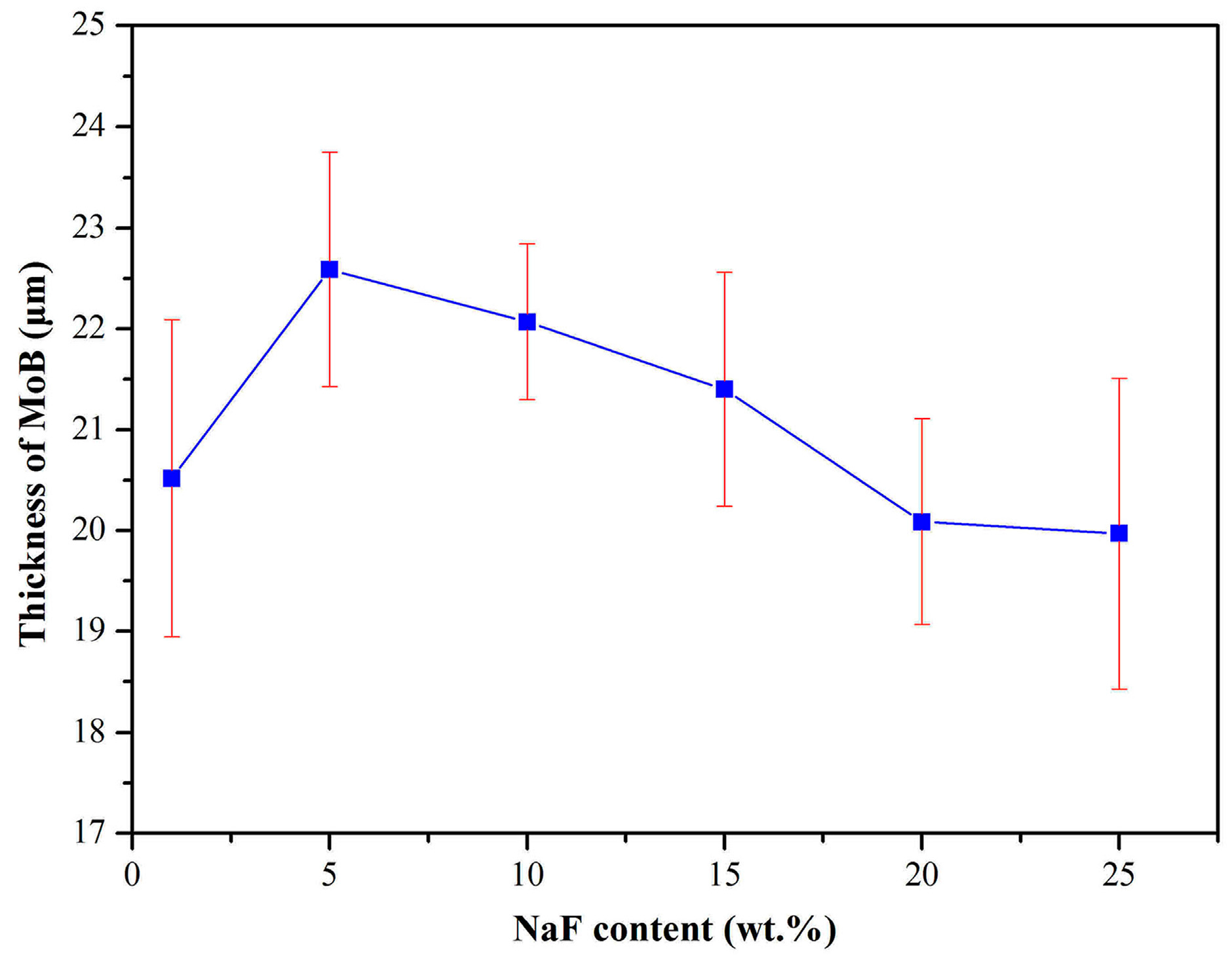
Figure 8.
The variation of the MoB coating thickness with the holding time.
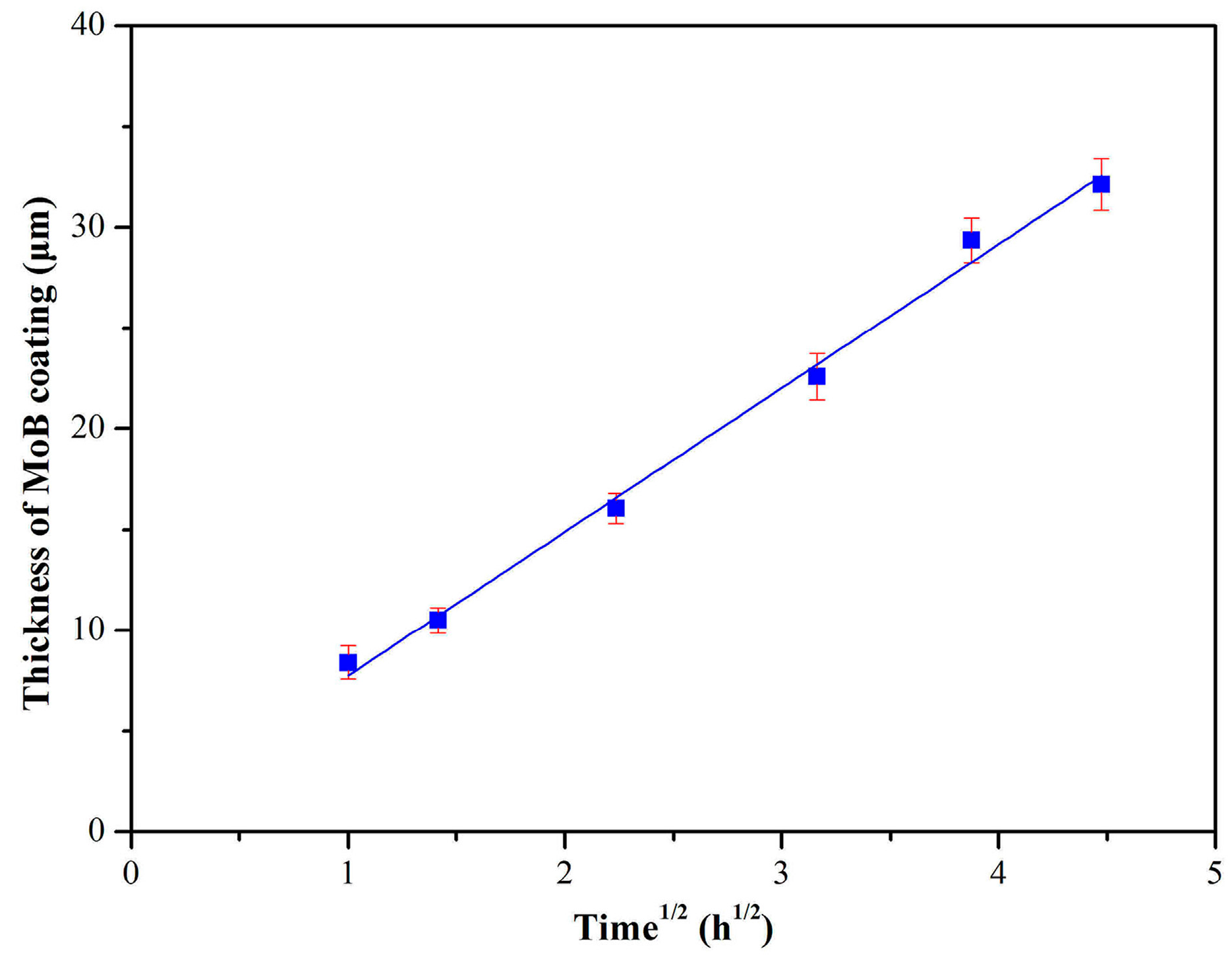
Figure 9.
The relationship between the thickness of the MoB coating and the deposition temperature.
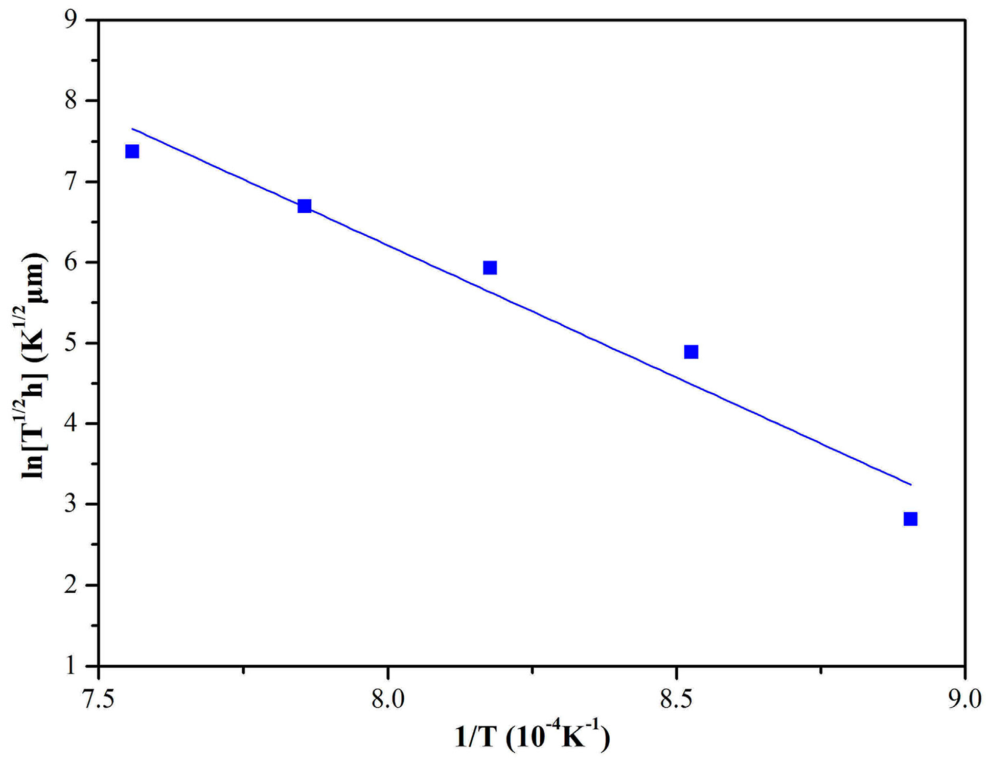
Figure 10.
The relationship between the coating thickness and the B content.
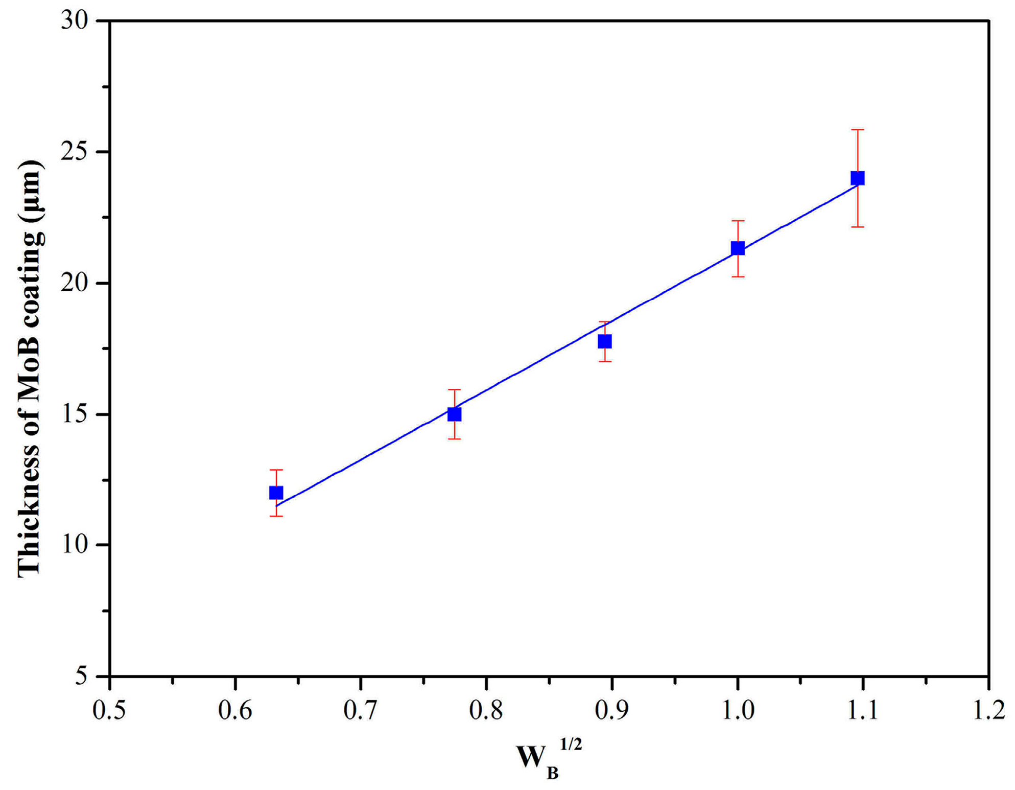
Figure 11.
The mass change of uncoated and coated MoB Mo samples during isothermal oxidation test.
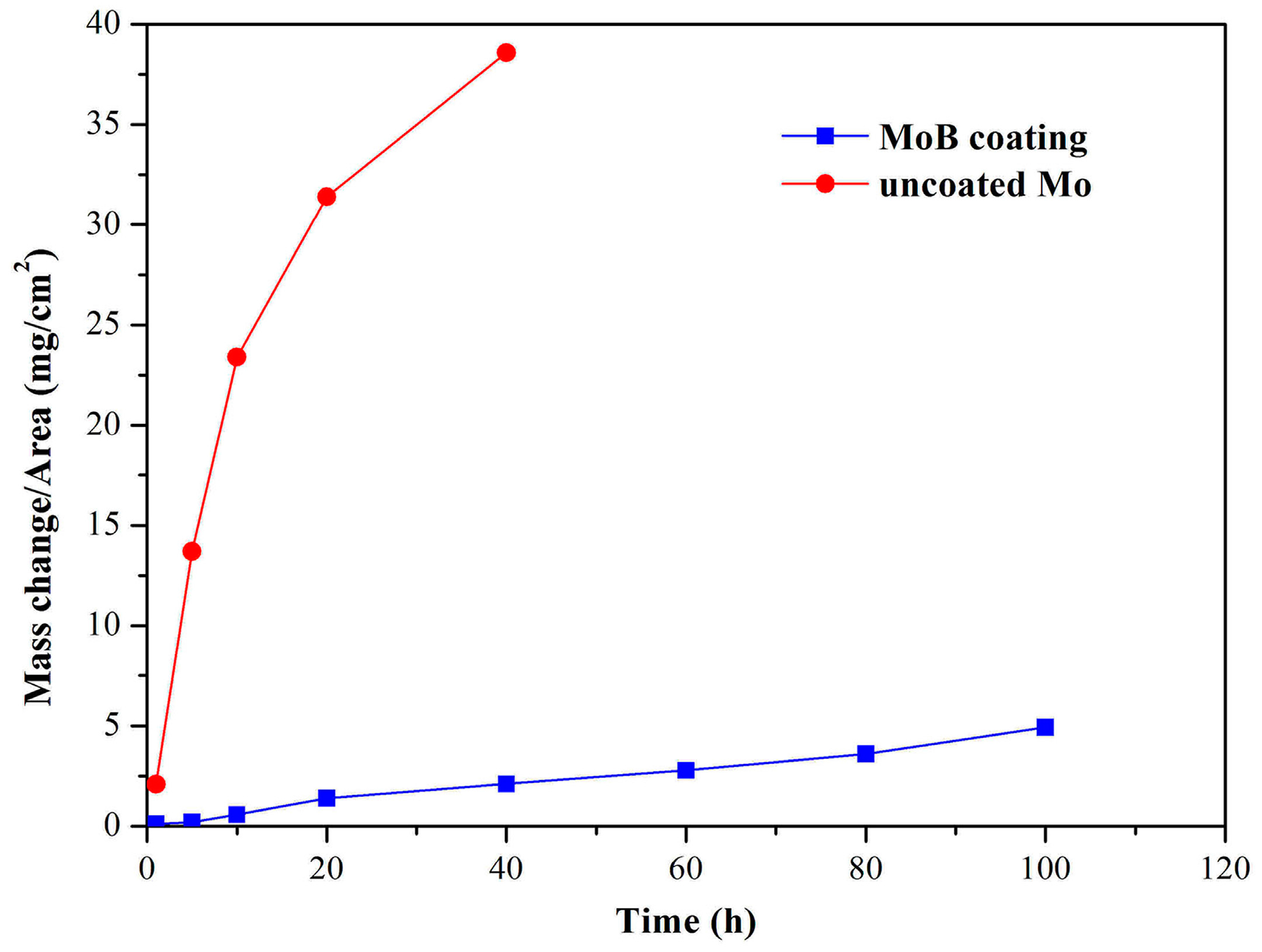
Figure 12.
The relationships between the squared mass change per unit area of the uncoated and coated Mo and the oxidation time during isothermal oxidation at 600 °C in air.
Figure 12.
The relationships between the squared mass change per unit area of the uncoated and coated Mo and the oxidation time during isothermal oxidation at 600 °C in air.
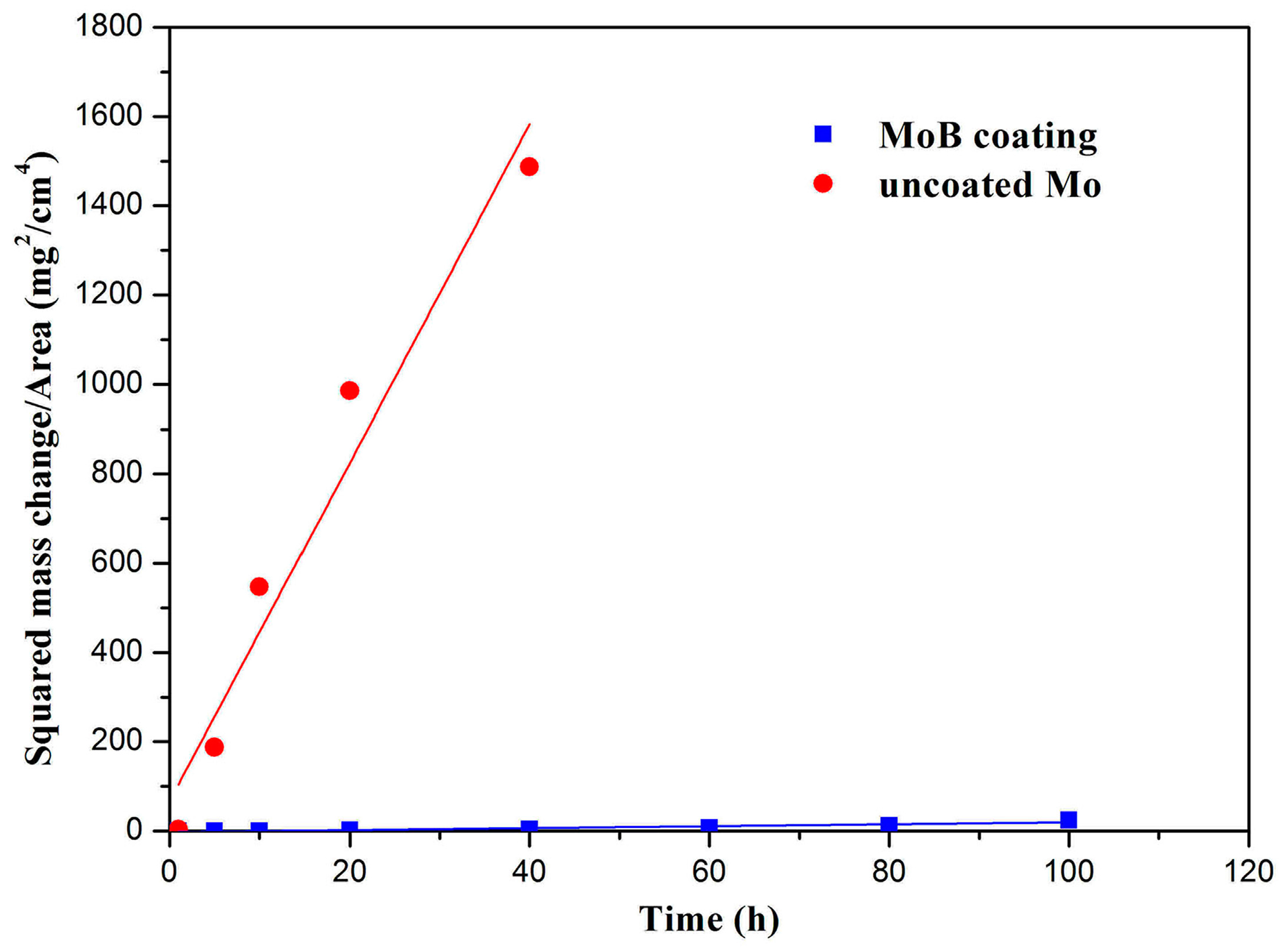
Figure 13.
The surface XRD pattern of MoB coating on Mo after oxidation.

Figure 14.
The surface (a) and cross-sectional (b) images of MoB coating after oxidation.


Table 1.
Hardness (Indentation hardness (HIT)) and elastic modulus (EIT) of MoB coating.
| Coating | HIT (GPa) | Hardness (HV) | EIT (GPa) |
|---|---|---|---|
| MoB | 33.81 | 3130.85 | 519.31 |
Table 2.
The oxidation rate constant (kp) of uncoated and coated Mo at 600 °C.
| Temperature (°C) | kp (mg2·cm−4·h−1) | |
|---|---|---|
| Pure Mo | MoB | |
| 600 | 37.91 | 0.218 |
© 2018 by the authors. Licensee MDPI, Basel, Switzerland. This article is an open access article distributed under the terms and conditions of the Creative Commons Attribution (CC BY) license (http://creativecommons.org/licenses/by/4.0/).
Share and Cite
MDPI and ACS Style
Wang, Y.; Shi, H.; Yan, J.; Wang, D. Preparation and Characterization of MoB Coating on Mo Substrate. Metals 2018, 8, 93. https://doi.org/10.3390/met8020093
AMA Style
Wang Y, Shi H, Yan J, Wang D. Preparation and Characterization of MoB Coating on Mo Substrate. Metals. 2018; 8(2):93. https://doi.org/10.3390/met8020093
Chicago/Turabian StyleWang, Yi, Haiyan Shi, Jianhui Yan, and Dezhi Wang. 2018. "Preparation and Characterization of MoB Coating on Mo Substrate" Metals 8, no. 2: 93. https://doi.org/10.3390/met8020093
Note that from the first issue of 2016, this journal uses article numbers instead of page numbers. See further details here.