Process Chain for the Production of a Bimetal Component from Mg with a Complete Al Cladding

Virtual Production Engineering, Chemnitz University of Technology, 09111 Chemnitz, Germany
*
Author to whom correspondence should be addressed.
Metals 2018, 8(2), 97; https://doi.org/10.3390/met8020097
Submission received: 2 January 2018
/
Revised: 15 January 2018
/
Accepted: 19 January 2018
/
Published: 27 January 2018
(This article belongs to the Special Issue Scientific and Engineering Progress on Aluminum-Based Light-Weight Materials: Research Reports from the German Collaborative Research Center 692)
Abstract
:With respect to its density, magnesium (Mg) has a high potential for lightweight components. Nevertheless, the industrial application of Mg is limited due to, for example, its sensitivity to corrosion. To increase the applicability of Mg, a process chain for the production of a Mg component with a complete aluminum (Al) cladding is presented. Hydrostatic co-extrusion was used to produce bar-shaped rods with a diameter of 20 mm. The bonding between the materials was verified by ultrasonic testing. Specimens with a length of 79 mm were cut off from the rods and forged by using a two-staged process. After the first step (Heading), the Mg core was removed partially by drilling to ensure a complete enclosing of the remaining Mg during the second forging step (Net shape forging). The geometry of the drilling hole and the heading die design were dimensioned with the Finite Element-simulation software FORGE. Hence, a complete Al-enclosed Mg component was achieved by using the described process chain and forming processes. Microstructural investigations confirm the formation of an intermetallic interface as expected.
1. Introduction
The use of lightweight construction and materials is one way for the automotive industry to limit CO2 emissions. However, the weight-saving potential of using a single material is limited. Material composites and composite materials can contribute to overcome this challenge by combining two or more different or similar materials. This results in tailored properties and emphasizes the positive properties of the materials and reduces the negative ones. With respect to weight saving, the use of lightweight materials is obvious, and especially the combination of Al and Mg as a material composite. Mg has a low density, but it is sensitive to corrosion. Al alloys (6xxx) provide corrosion resistance and are low-cost lightweight materials. Consequently, a material composite made from Al and Mg should be significantly lighter, depending on the content of Mg, and provide complete protection of the Mg from corrosive media. One approach is the production of a bar-shaped rod by co-extrusion and its use as a semi-finished product for a subsequent forging process. Co-extrusion has been investigated by several authors with different material combinations since the early 1970s [1,2,3,4,5]. Material composites from Mg and Al showed a good formability in contrast to other material combinations, where core fracture was observed [6]. Many investigations have focused on pressing billet geometry, variations of cladding and core material (cladding: Mg, core: Al, and vice versa) [7], or geometry of co-extruded products (e.g., sheets [6], profiles [8], tubes [9] or bar-shaped rods [10,11,12]). Such studies have shown that an interface between Al and Mg is formed by diffusion during co-extrusion. It comprises two intermetallic phases, Al3Mg2 and Al12Mg17, and ensures the connection between the materials. Their structure and properties depend on the formation conditions [10,11,12]. Due to the brittle mechanical properties, the co-extrusion often results in cracks along the interface. The fracture and mechanical properties of the material composites have been investigated in detail by Lehmann [13,14] and Kirbach [15,16]. They found that the interface tensile strength at room temperature was 125 to 145 MPa, and the formability increased at elevated temperatures. The work on the forming of metallic macroscopic composites is very limited. Li et al. produced Al-Mg-Al sheets by hot roll bonding, and investigated the deep drawability [17]. Other investigations have focused on the forging of powder composites [18,19] or metal matrix composites with different particle reinforcement [20,21]. Foydl et al. investigated steel-reinforced aluminum. They used continuous reinforcement only for co-extrusion and discontinuous for forging, and produced a component with different distributions of the wire reinforcement [22]. This was confirmed by Feuerhack [23], who investigated the processing of co-extruded Al-Mg rods by die forging. It was shown that the interface remains intact if compression stresses dominate. Shear stresses caused a fragmentation of the interface, but a new interface was built between the fragments [23].
At the front ends of the bar-shaped rods, the Mg is left unprotected. This problem also remains after subsequent forging. To prevent the Mg from corrosion and increase the durability of the components, it is essential to achieve a complete enclosing by the Al cladding. Therefore, the production of a bimetal component from Mg with a complete Al cladding by using conventional forming processes was investigated.
2. Materials and Methods
For the production and processing of the Al-Mg material composites, commercially available alloys of magnesium (AZ31) and aluminum (AA-6082) were used. Their chemical compositions are given in Table 1. The bar-shaped rods had a diameter of 80 mm (Al) and 60 mm (Mg). For the production of the pressing billets for the co-extrusion process, a blind hole of 58 mm in diameter was drilled and machined into 290 mm-long sections of the Al rods. The Mg rods were also machined to a diameter of 58 mm, and were loose fit into the Al. Figure 1a,b shows a cross-sectional schematic view of the pressing billets with a Mg core and an Al cladding.
2.1. Hydrostatic Co-Extrusion
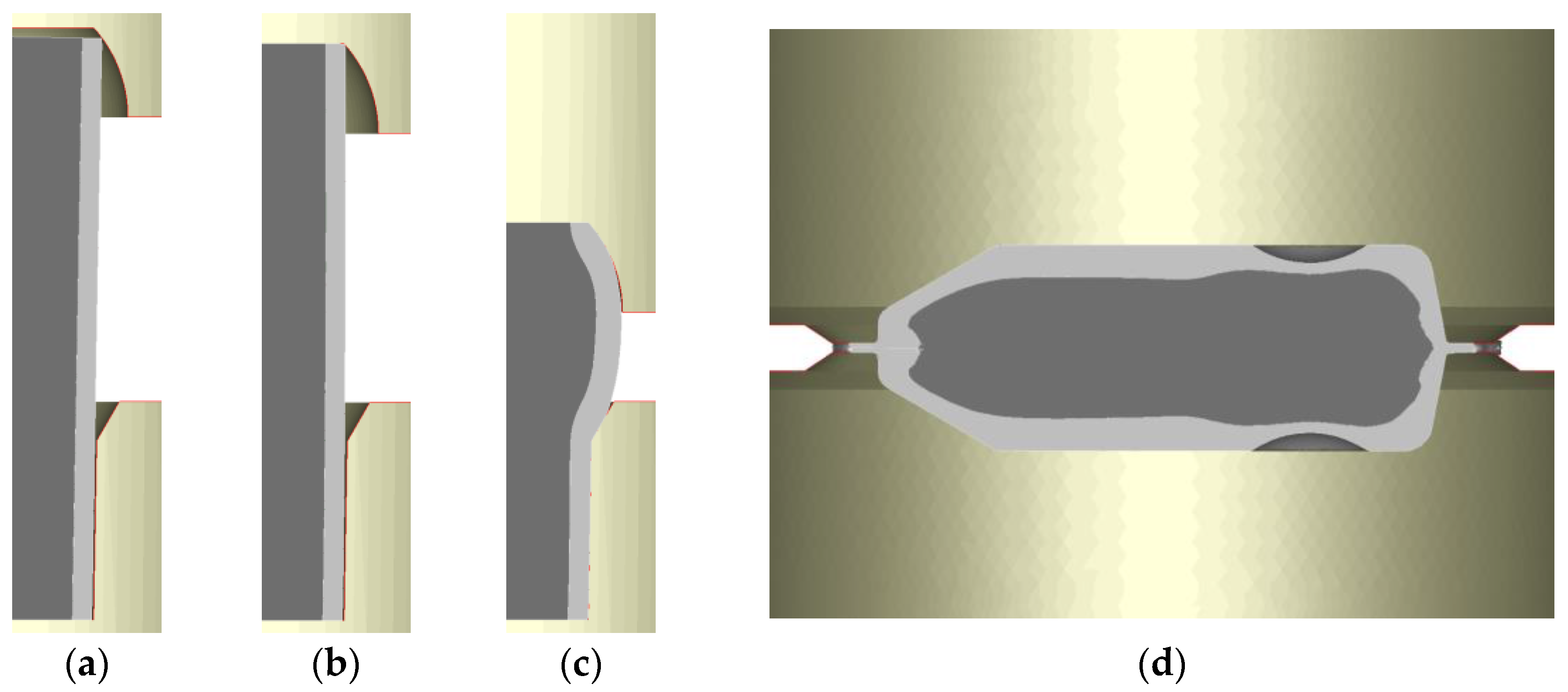
The hydrostatic co-extrusion process of Al-Mg material composites was extensively investigated by Kittner [24,25,26]. The container of the press limited the dimensions of the pressing billet to a length of 290 mm and an outer diameter of 80 mm. He varied parameters such as material combinations, the ratio of cladding and core outer diameter, die geometries, and pressing temperatures. The best results were achieved with the material combination AA-6082 (cladding) and AZ31 (core) pressed at a temperature of about 300 °C with an extrusion ratio of 16. Thus, these parameters were used in this investigation. The pressing billet geometry used by Kittner is given in Figure 1a. This geometry with its conical shape leads to contact between the Al-Mg interface and the extrusion die during infeed, as shown in Figure 1c. Thus, lubricant is pressed into the gap between the materials, often preventing bonding. Therefore, the pressing billet geometry was adapted as shown in Figure 1b,d by flattening and shortening the Mg core. The Al protrudes the Mg, and a touching of the contact zone can be prevented.
After the production of the pressing billets, they were heated to extrusion temperature and lubricated before the insertion into the extrusion press. It must be ensured that the lubricant is only applied on the outer surfaces of the cladding material; otherwise, the lubricant may reach the contact zone between the materials and prohibit the bonding between them during co-extrusion. Subsequently, the pressing billets were inserted into the extrusion press and co-extruded with a plunger speed of 3.6 mm/s, as presented schematically in Figure 1c,d. The chamfer at the front end of the pressing billet seals the hydraulic fluid (Ricinus oil). Thus, the pressing pressure can be built up. The hydraulic fluid also acts as a lubricant, by being pressed and hauled between the die and pressing billet. It was found that a mechanical cleaning of the extrusion die from adhering aluminum after each extrusion significantly increases the surface quality of the strands. With the given dimensions of the pressing billet, extruded strands with a length of about 3500 mm and an outer diameter of 20 mm were produced.
2.2. Die Forging
The co-extruded strands were used as semi-finished products for the forging investigations. Basic investigations on the formability of the material composites by die forging were performed by Feuerhack [27,28]. He used three one-stage processes with simple die geometries (as shown in Figure 2) to induce different stress conditions in the components, especially at the interface. The process parameters—including die temperature, specimen temperature and tribology—were investigated regarding their influence on the forging results. He found that best results were achieved with a lubricated die (Gleitmo 820, FUCHS lubritec, Kaiserslautern, Germany) at a temperature of 200 °C and a specimen temperature of 300 °C.
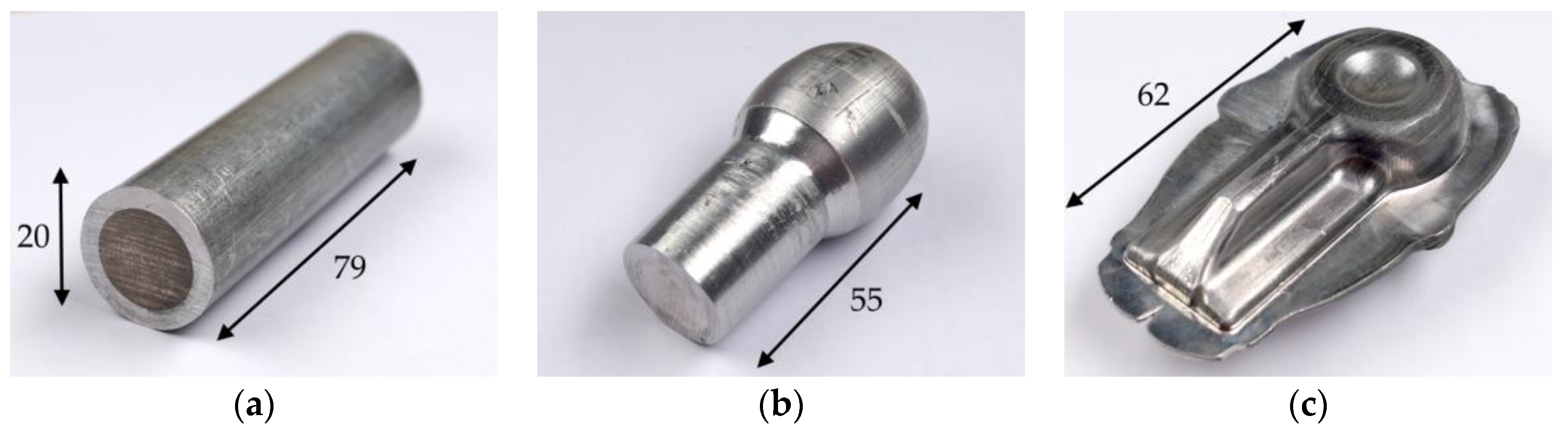
Based on these findings, he developed a more complex component he called SMART-Body. The production of the SMART-Body is a two-stage process comprising heading and net shape forging. This component was also used in the present investigation, and the process steps are given in Figure 3. To achieve a complete filling of the die, the length of the initial billet was increased by 11 mm to 79 mm and cut off from the strand (Figure 3a). The risk of buckling during heading also increased. With an adaptation of the heading die as presented in Section 2.3, this problem could be solved. After cutting off, the billet was heated for half an hour to 350 °C, and the heading die was heated to 200 °C. Subsequently, the billet was forged (Figure 3b). A mechanical press (Raster Zeulenroda, PED 100.3-S4, Zeulenroda, Germany) with a maximum force of 1000 kN was used for the investigation. Thereafter, the Mg core was removed partially by drilling at both front ends of the preform. Variation of the drill hole geometry, drilling depth, and forging temperature was investigated to find the combination for the complete cladding of the Mg during net shape forging. Based on numerical analysis, a drill with a diameter of 15 mm and a drilling angle of 118° was chosen. The drilling depth was 3 mm. Subsequently, the preform was heated up to 350 °C again and forged to net shape with a die temperature of 200 °C (Figure 3c). MoS2 was used for lubrication.
2.3. Numerical Analysis of the Forging Process
The development of the process chain was fully accompanied by numerical investigations for parameter identification, process design, and process understanding. A detailed analysis of the co-extrusion process with respect to the prediction of the bonding can be found at KITTNER [26]. Basic investigations on the formability of the material composites by die forging were performed by Feuerhack [28]. He used the simulation system FORGE by Transvalor with implicit time integration. The software was also used for the forging processes in the present investigation based on the process parameters identified by Feuerhack [23,28]. The models can be seen in Figure 4. To limit the computation time, all dies are modeled as rigid bodies, and only the billet was fully deformable. The billet comprises the two bodies cladding (Al) and the core (Mg), connected by a sticking condition, and was thermo-mechanically coupled. The temperature field of the Al and Mg was measured during heating to forging temperature, and no significant differences were found. In accordance with Feuerhack [28], the heat transfer coefficient between the materials was set to 106 W∙(m2∙K)−1/2 to ensure an equal temperature distribution within the component. The heat transfer between the dies and the component was set to 30 × 103 W∙(m2∙K)−1/2 [28]. In the beginning of the simulation, the die temperature was set to 200 °C and the billet temperature to 350 °C. Tetrahedral elements with a size of 0.6 were used for meshing the billet and 7.6 for the dies. The material data is from the literature [29,30,31] and Hensel–Spittel equation was used to model the material behavior. It considers the temperature-, strain-, and stress-dependence of materials. The forming history from heading was also considered during net shape forging. Based on experimental investigations, a Tresca friction factor of 0.2 was used to model the lubrication conditions.
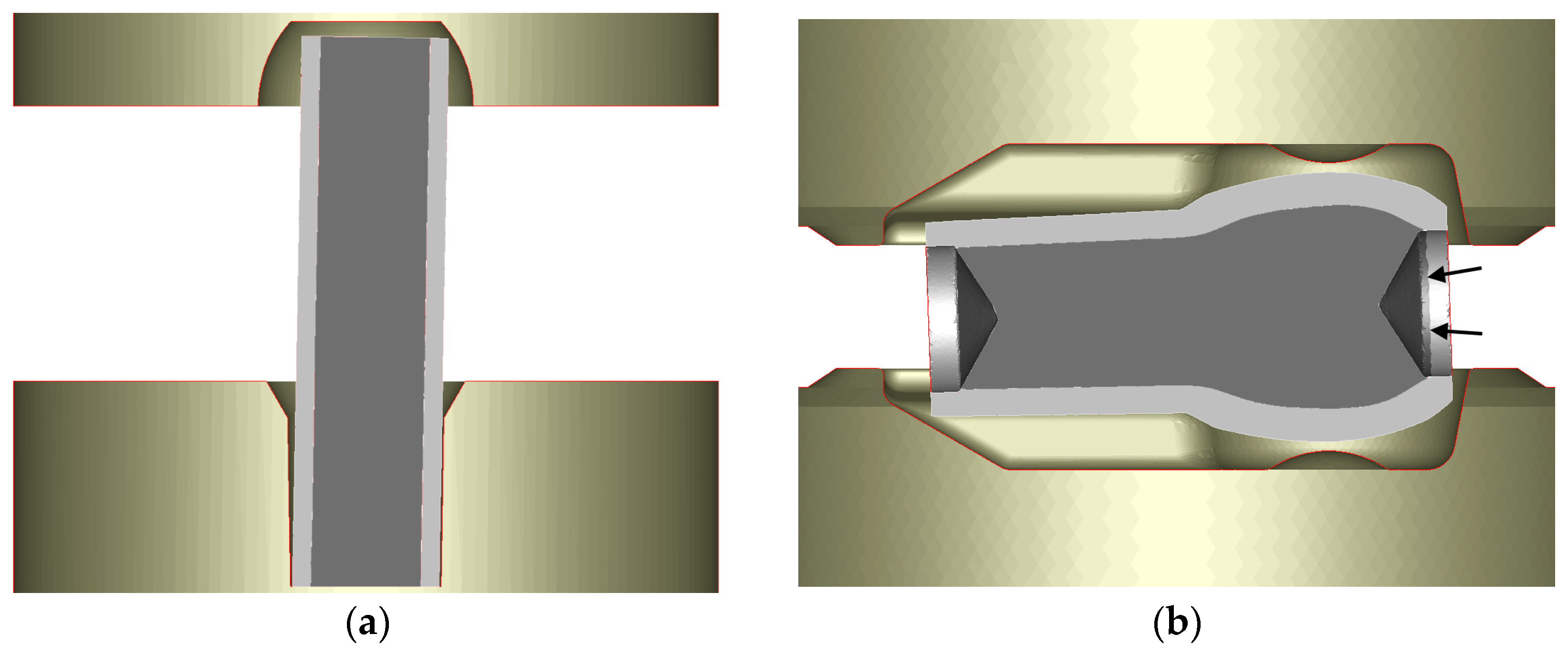
Prior to the forging experiments, the heading process was investigated. To ensure a complete die filling, a longer billet was used. Therefore, the model of the former used heading die was adapted to prevent the specimens from buckling. By using a longer billet, the lower die was deepened 9 mm to keep the same size of the head. Additionally, a cavity with the same geometry as the upper part of the head was machined into the upper die. The cavity ensures centering of the billet at the beginning of the heading process, and buckling should be prevented. This was verified with an inclined billet, as can be seen in Figure 4a. The angle between the middle axes of the forging dies and the billet was 1°. Based on these results, the forging dies were also adapted.
After heading, the model of the billet was transferred into a new simulation for the investigation of the removal of the Mg-core and its influence on net shape forging. FORGE provides a special trimming tool to remove material volume by deleting elements. Removing material volume is often problematic in numerical analysis, especially if the model is used in further processing. The elements are connected to forming data (stress, strain, force, etc.), which are also deleted. This missing data can lead to a failing remeshing during transfer from one simulation to the other. In this case, the tool was used to remove the Mg core for the net shape forging after heading with no loss of forming data. Different geometries of the drilling hole (conical, blind), drilling depths (1–4 mm), and forging temperature (300 °C, 350 °C, 400 °C) were investigated and validated with experiments. Figure 4b shows the headed preform with removed Mg core on both sides with a depth of 3 mm and a drilling angle of 118° placed in the net shape forging die.
3. Results
3.1. Hydrostatic Co-Extrusion
Figure 5a–c shows the longitudinal cross-sections of the co-extruded strands. Due to the conical shape of the formerly used pressing billet, there is a section of about 200 mm at the beginning of the strand, where the Mg has no Al cladding (Figure 5a). By contrast, the improved pressing billet geometry results in an enclosed Mg core from the beginning of the process (Figure 5b). The process parameters of the co-extrusion must be adjusted in such a way that an undamaged strand and a sufficient bonding between the materials are ensured. Due to the substantial surface enlargement during co-extrusion, the oxide layers on the materials break up, and the pure materials enter in contact. This results in an accelerated diffusion process and the formation of an interface with two intermetallic phases, Al3Mg2 and Al12Mg17, as shown in Figure 5d,e.
After co-extrusion, the interface had a thickness of 1–2 µm. It is essential to keep the extrusion temperature below the eutectic melting temperatures (436 °C or 450 °C) of the intermetallic phases; otherwise, a eutectic cast microstructure develops at the interface with worse mechanical properties than a diffusion-based microstructure [14,26].
Ultrasonic testing is a straightforward method of investigating whether bonding was achieved. With this non-destructive method, the entire strand can be evaluated by the ultrasonic reflections, as shown in Figure 6. If there is a complete bonding, the ultrasonic waves are reflected at the opposite edge of the strand, resulting in one single strong peak. The two smaller peaks arise from the partial reflection at the interface (Figure 6a). If there is no bonding, the ultrasonic waves are reflected completely and can be identified by many strong peaks corresponding to the repeated reflection at the interface (Figure 6b).
3.2. Die Forging
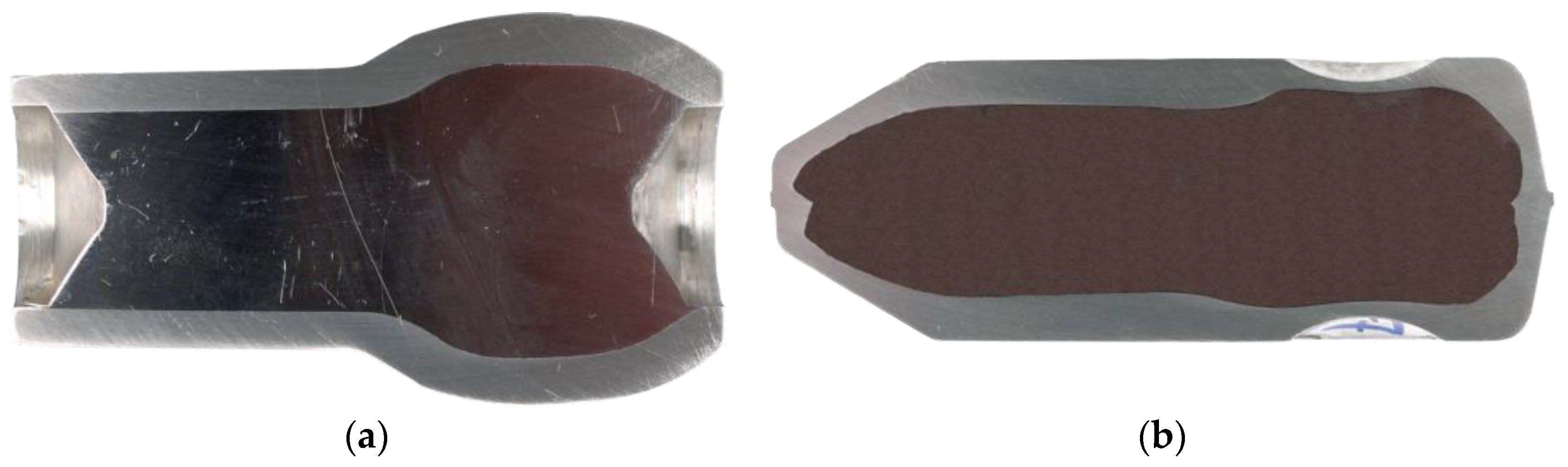
The investigations on the removal of the Mg core showed that a conical drilling hole results in a complete closing of the front ends, as shown in Figure 7. A complete closing was achieved if the drilling depth was at least 2 mm. An overly-deep drilling hole can lead to the voids remaining between Al and Mg. If the drilling hole is not deep enough, the enclosure is incomplete. The increase of the temperature increases the flash formation by lowering the yield stress. This can promote a flowing of the Mg into the flash due to the increased formability. The interaction of these parameters depends on the component geometry, and must be evaluated for each geometry individually. For the SMART-Body, a complete enclosure of the Mg-core was achieved with a 15 mm conical drilling hole and a depth of 3 mm forged at 350 °C. Depending on the state of closing at the front ends, forging forces of 800 to 1000 kN were measured.
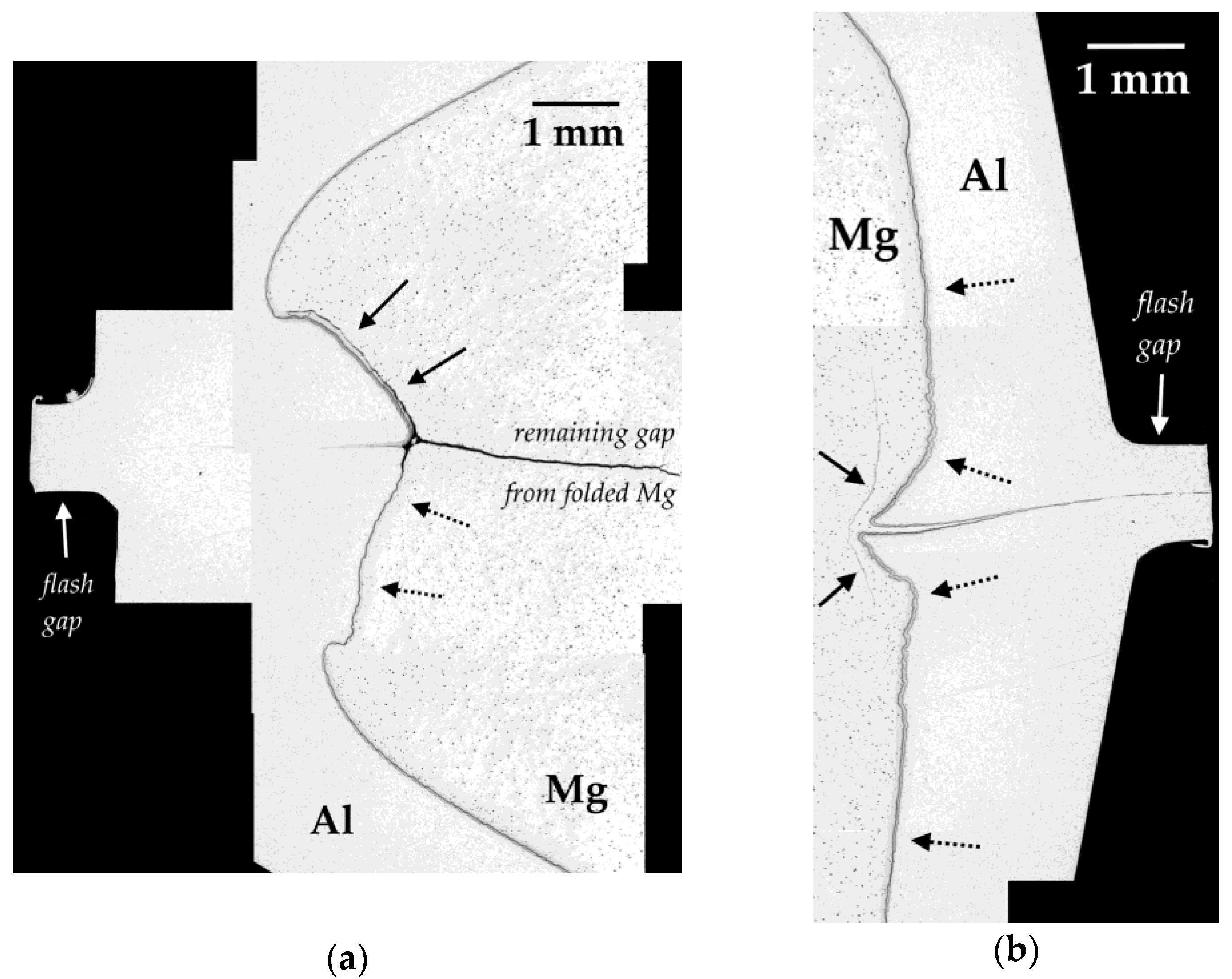
Figure 8 shows the micrographs of closed front ends and the flash region. They confirm a complete Al cladding. Due to the pressure during forging, the Al is formed around the front ends of the Mg and flows out of the flash gap. The conical Mg core is folded, as indicated by the gap in Figure 8a. A precise positioning of the drilling hole is essential to ensure a complete removal of the Mg at the drilling hole walls. This was the case in the lower part of the component. The interface-free region (dashed arrows) indicates the former drilling hole wall folded onto the Mg. No diffusion was observed between Al and Mg in this region. Due to the compression stress and the missing surface enlargement, the oxide layers (not visible) could not be broken up, and hence prohibit diffusion. In the upper part, the interface (black arrows) was not removed during drilling, and thus it folded onto the Mg. The gap indicates the former drilling hole wall. One part of the interface was partially pressed into the flash gap. Thus, the interface could be pressed out through the flash gap and lower the corrosion resistance by preventing diffusion between the Al. The contact zone of the Al can hardly be identified in Figure 8a. Due to the forming pressure, high strains and temperature influence in that region, and self-diffusion between Al is supposed. No self-diffusion is observed between Mg.
Due to the different Mg core geometry at the opposite side, it is not possible to remove the Mg sufficiently (also see arrows in Figure 3b). As shown in Figure 8b, the drilling hole walls with the remaining interface were formed onto the Mg, similar to Figure 8a. The contact zone is indicated by black arrows. Together with Mg, the interface was also pressed through the flash gap. Self-diffusion was not observed here, being potentially inhibited by lubricant and other contaminants on the surfaces, which are also pressed through the flash gap. Such impurities must be eliminated to allow diffusion and prevent the contact zone from corrosion. Furthermore, the micrographs show an increase in interface thickness (dashed arrows in Figure 8b). The increase starts from the average value of about 27 µm and reaches values of about 35 µm, and cannot be related to differences in thermal history. This phenomenon was found and described by Feuerhack [28] during upsetting and is confirmed in the present investigation. The hydrostatic pressure during compression of the interface offers a certain formability of the interface and prevents it from fragmentation.
3.3. Numerical Analysis of the Forging Process
The function of the cavity in the upper die is demonstrated in Figure 9a–c for several process steps. After the contact of the inclined billet with the cavity (Figure 9a), it is aligned to the center axis of the forging dies (Figure 9b). Thus, the heading process can be finished without buckling of the billet (Figure 9c). Figure 9d shows the simulation results of the net shape forging of the SMART-Body with a partially-removed Mg core (conical; diameter 15 mm; depth 3 mm). A comparison with the cross-section of the forged component in Figure 7c shows a good agreement between the shape of the Mg core obtained from Finite Element simulation and experiment. Furthermore, the enclosure of the Mg core by the Al is in good agreement with the experimental results. With respect to the chosen boundary conditions, the forging force of about 900 kN was calculated.
4. Conclusions
A process chain for the production of a completely Al-cladded bimetal component with Mg core has been presented. Semi-finished products are produced by hydrostatic co-extrusion at 300 °C with a diameter of 20 mm and a length of about 3500 mm. The bimetal component was produced by die forging in a two-stage process. Billets with a length of 79 mm were cut off from the bar-shaped rods and forged at a temperature of 350 °C. The first process step—heading—is to achieve an appropriate distribution of material volume before net shape forging. To prevent the billets from buckling, the heading die was adapted with an additional cavity in the upper die. The cavity ensures centering of the billets in the first process steps. After heading, the Mg core was partially removed by drilling at the front ends. The remaining and protruding Al encloses the Mg core during the second forging step. The contact zone of the enclosing Al is located in the center of the flash gap and self-diffusion is supposed between the Al-cladding at the front ends.
The described process chain shows one approach to producing lightweight components from a metallic material composite. However, the size of such components is limited with respect to the size of the co-extruded rods. Nonetheless, there is strong potential in this field for future investigations. The focus might be on the improvement of this process chain or the development of other strategies and material combinations.
Acknowledgments
The authors are grateful to the German Research Foundation for their financial support of these investigations.
Author Contributions
W. Förster was responsible for performing the experimental and numerical investigations and wrote this paper. All authors have discussed the results.
Conflicts of Interest
The authors declare no conflict of interest.
References
- Osakada, K.; Limb, M.; Mellor, P.B. Hydrostatic extrusion of composite rods with hard cores. Int. J. Mech. Sci. 1973, 15, 291–307. [Google Scholar] [CrossRef]
- Story, J.M.; Avitzur, B.; Hahn, W.C. The effect of receiver pressure on the observed flow pattern in the hydrostatic extrusion of bimetal rods. ASME J. Eng. Ind. 1976, 98, 909–913. [Google Scholar] [CrossRef]
- Avitzur, B.; Wu, R.; Talbert, S.; Chou, Y.T. An analytical approach to the problem of core fracture during extrusion of bimetal rods. ASME J. Eng. Ind. 1985, 107, 247–253. [Google Scholar] [CrossRef]
- Kleiner, M.; Schomäcker, M.; Schikorra, M.; Klaus, A. Manufacture of extruded and continuously reinforced aluminum profiles for ultra-lightweight constructions. Mater. Werkst. 2004, 35, 431–439. [Google Scholar] [CrossRef]
- Jang, D.H.; Hwang, B.B. Deformation Analysis of Co-Extrusion Process of Aluminum Alloy and Copper Alloy. Key Eng. Mater. 2007, 340, 645–648. [Google Scholar] [CrossRef]
- Engelhardt, M.; Grittner, N.; Haverkamp, H.; Reimche, W.; Bormann, D.; Bach, F.-W. Extrusion of hybrid sheet metals. J. Mater. Process. Technol. 2012, 212, 1030–1038. [Google Scholar] [CrossRef]
- Feng, B.; Xin, Y.; Hong, R.; Yu, H.; Wu, Y.; Liu, Q. The effect of architecture on the mechanical properties of Mg–3Al–1Zn rods containing hard Al alloy cores. Scr. Mater. 2015, 98, 56–59. [Google Scholar] [CrossRef]
- Muehlhause, J.; Gall, S.; Mueller, S. Simulation of the co-extrusion of hybrid Mg/Al profiles. Key Eng. Mater. 2010, 424, 113–119. [Google Scholar] [CrossRef]
- Golovko, O.; Bieliaiev, S.M.; Nürnberger, F.; Danchenko, V.M. Extrusion of the bimetallic aluminum-magnesium rods and tubes. Forsch. Ingenieurwesen 2015, 79, 17–27. [Google Scholar] [CrossRef]
- Negendank, M.; Mueller, S.; Reimers, W. Coextrusion of Mg–Al macro composites. J. Mater. Process. Technol. 2012, 212, 1954–1962. [Google Scholar] [CrossRef]
- Priel, E.; Ungarish, Z.; Navi, N.U. Co-extrusion of a Mg/Al composite billet: A computational study validated by experiments. J. Mater. Process. Technol. 2016, 236, 103–113. [Google Scholar] [CrossRef]
- Paramsothy, M.; Srikanth, N.; Gupta, M. Solidification processed Mg/Al bimetal macrocomposite: Microstructure and mechanical properties. J. Alloys Compd. 2008, 461, 200–208. [Google Scholar] [CrossRef]
- Lehmann, T.; Stockmann, M.; Kittner, K.; Binotsch, C.; Awiszus, B. Fracture mechanical properties of Al/Mg compounds and yield behavior of the material during the production process. Mater. Werkst. 2011, 42, 612–623. [Google Scholar] [CrossRef]
- Lehmann, T. Experimentell-numerische Analyse Mechanischer Eigenschaften von Aluminium/Magnesium-Werkstoffverbunden. Ph.D. Thesis, Chemnitz University of Technology, Chemnitz, Germany, 29 June 2012. [Google Scholar]
- Kirbach, C.; Lehmann, T.; Stockmann, M.; Ihlemann, J. Digital image correlation used for experimental investigations of Al/Mg compounds. Strain 2015, 51, 223–234. [Google Scholar] [CrossRef]
- Kirbach, C.; Stockmann, M.; Ihlemann, J. Rate dependency of interface fragmentation in Al-mg-compounds. In Proceedings of the Conference Abstract of the 34th Danubia-Adria Symposium on Advances in Experimental Mechanics, Trieste, Italy, 19–22 September 2017; pp. 167–168, ISBN 978-88-8303-863-1. [Google Scholar]
- Li, C.; Chi, C.; Lin, P.; Zhang, H.; Liang, W. Deformation behavior and interface microstructure evolution of Al/Mg/Al multilayer composite sheets during deep drawing. Mater. Des. 2015, 77, 15–24. [Google Scholar] [CrossRef]
- Behrens, B.-A.; Kosch, K.-G.; Frischkorn, C.; Vahed, N.; Huskic, A. Compound forging of hybrid powder-solid-parts made of steel and aluminum. Key Eng. Mater. 2012, 504, 175–180. [Google Scholar] [CrossRef]
- Shishkina, Y.A.; Baglyuk, G.A.; Kurikhin, V.S.; Verbylo, D.G. Effect of the deformation scheme on the structure and properties of hot-forged aluminum-matrix composites. Powder Metall. Met. Ceram. 2016, 55, 5–11. [Google Scholar] [CrossRef]
- Liao, W.; Ye, B.; Zhang, L.; Zhou, H.; Guo, W.; Wang, Q.; Li, W. Microstructure evolution and mechanical properties of SiC nanoparticles reinforced magnesium matrix composite processed by cyclic closed-die forging. Mater. Sci. Eng. A 2015, 642, 49–56. [Google Scholar] [CrossRef]
- Purohit, R.; Qureshi, M.M.U.; Kumar, B. Effect of Forging on Aluminum Matrix Nano Composites: A Review. Mater. Today Proc. 2017, 4, 5357–5360. [Google Scholar] [CrossRef]
- Foydl, A.; Pfeiffer, I.; Kammler, M.; Pietzka, D.; Matthias, T.; Jäger, A.; Tekkaya, A.E.; Behrens, B.-A. Manufacturing of Steel-reinforced Aluminum Products by Combining Hot Extrusion and Closed-Die Forging. Key Eng. Mater. 2012, 504, 481–486. [Google Scholar] [CrossRef]
- Feuerhack, A.; Binotsch, C.; Awiszus, A. Formability of hybrid aluminum-magnesium compounds. Key Eng. Mater. 2013, 554, 21–28. [Google Scholar] [CrossRef]
- Kittner, K.; Awiszus, B. Numerical and experimental investigations of the production processes of coextruded Al/Mg-compounds and the strength of the interface. Key Eng. Mater. 2019, 424, 129–135. [Google Scholar] [CrossRef]
- Kittner, K.; Awiszus, B. The process of co-extrusion—An analysis. Key Eng. Mater. 2012, 491, 81–88. [Google Scholar] [CrossRef]
- Kittner, K. Integrativer Modellansatz bei der Co-Extrusion von Aluminium-Magnesium-Werkstoff-Verbunden. Ph.D. Thesis, Chemnitz University of Technology, Chemnitz, Germany, 11 May 2012. [Google Scholar]
- Binotsch, C.; Nickel, D.; Feuerhack, A.; Awiszus, B. Forging of Al-Mg compounds and characterization of interface. Procedia Eng. 2014, 81, 540–545. [Google Scholar] [CrossRef]
- Feuerhack, A. Experimentelle und Numerische Untersuchungen von Al-Mg-Verbunden Mittels Verbundschmieden. Ph.D. Thesis, Chemnitz University of Technology, Chemnitz, Germany, 23 May 2014. [Google Scholar]
- Kammer, C. Aluminium-Taschenbuch, 16th ed.; Aluminium-Verlag: Düsseldorf, Germany, 2000; ISBN 3870172754. [Google Scholar]
- Kammer, C. Magnesium-Taschenbuch, 1st ed.; Aluminium-Verlag: Düsseldorf, Germany, 2000; ISBN 3870172649. [Google Scholar]
- Doege, E.; Janssen, S.; Wieser, J. Characteristic values for the forming of the magnesium alloy AZ31. Mater. Werkst. 2001, 32, 48–51. [Google Scholar] [CrossRef]
Figure 1.
Geometries of the pressing billets and material flow during co-extrusion. (a) Longitudinal cross-section of formerly used billet with conical shaped Mg core and (b) of the improved billet with shortened Mg core; (c) Material flow during infeed of the formerly used billet with contact of the Al-Mg interface on the extrusion die; (d) Improved pressing billet geometry ensures that only the Al is in contact with the extrusion die.
Figure 2.
Three simple geometries for the one-staged basic forging investigations. (a) Upsetting; (b) Spreading; (c) Rising [28].
Figure 2.
Three simple geometries for the one-staged basic forging investigations. (a) Upsetting; (b) Spreading; (c) Rising [28].
Figure 3.
Production stages of the bimetal component with dimensions in mm. (a) Initial billet, cut off from a co-extruded rod; (b) Preform after first forging step (Heading); (c) bimetal component after second forging step (Net shape forging).
Figure 3.
Production stages of the bimetal component with dimensions in mm. (a) Initial billet, cut off from a co-extruded rod; (b) Preform after first forging step (Heading); (c) bimetal component after second forging step (Net shape forging).

Figure 4.
Cross-sections of the numerical models for the forging processes. (a) Heading die with additional cavity in the upper die, to prevent the billets from buckling; (b) Preform after heading with partially-removed Mg core, placed in the net shape forging die; arrows indicate remaining Mg.
Figure 4.
Cross-sections of the numerical models for the forging processes. (a) Heading die with additional cavity in the upper die, to prevent the billets from buckling; (b) Preform after heading with partially-removed Mg core, placed in the net shape forging die; arrows indicate remaining Mg.

Figure 5.
Macro- and micrographs from the co-extruded rods. (a) Longitudinal cross-section of the beginning of the rod from the formerly used pressing billet with the Mg preceding the Al; (b) Improved pressing billet with the Al enclosing the Mg core; (c) transversal cross-section of the co-extruded rods. Micrographs of the interface on the (d) longitudinal and (e) transversal cross-section.
Figure 6.
Investigations on the bonding of the co-extruded rods by ultrasonic testing. (a) Ultrasonic signals indicating a complete bonding and (b) no bonding.
Figure 6.
Investigations on the bonding of the co-extruded rods by ultrasonic testing. (a) Ultrasonic signals indicating a complete bonding and (b) no bonding.
Figure 7.
Cross-sections of (a) the preform with partially-removed Mg core and (b) the net shape forged component.
Figure 7.
Cross-sections of (a) the preform with partially-removed Mg core and (b) the net shape forged component.

Figure 8.
Micrographs of the flash gap region at the front ends of the bimetal component.

Figure 9.
Cross-sections of the simulation results of the forging processes. (a–c) Centering and forming of the inclined billet by the cavity of the upper die; (d) Net shape forging of the SMART-Body with partially-removed Mg-core.
Figure 9.
Cross-sections of the simulation results of the forging processes. (a–c) Centering and forming of the inclined billet by the cavity of the upper die; (d) Net shape forging of the SMART-Body with partially-removed Mg-core.


Table 1.
Chemical compositions of the alloys used for this investigation.
| Composition in wt % | Al | Mg | Zn | Mn | Si | Cu | Fe | Ni | Ti | Cr |
|---|---|---|---|---|---|---|---|---|---|---|
| AA-6082 | Balance | 0.851 | 0.082 | 0.489 | 0.887 | 0.107 | 0.272 | - | 0.019 | 0.167 |
| AZ31 | 2.71 | Balance | 0.77 | 0.251 | 0.017 | <0.001 | <0.001 | <0.002 | - | - |
© 2018 by the authors. Licensee MDPI, Basel, Switzerland. This article is an open access article distributed under the terms and conditions of the Creative Commons Attribution (CC BY) license (http://creativecommons.org/licenses/by/4.0/).
Share and Cite
MDPI and ACS Style
Förster, W.; Binotsch, C.; Awiszus, B. Process Chain for the Production of a Bimetal Component from Mg with a Complete Al Cladding. Metals 2018, 8, 97. https://doi.org/10.3390/met8020097
AMA Style
Förster W, Binotsch C, Awiszus B. Process Chain for the Production of a Bimetal Component from Mg with a Complete Al Cladding. Metals. 2018; 8(2):97. https://doi.org/10.3390/met8020097
Chicago/Turabian StyleFörster, Wolfgang, Carolin Binotsch, and Birgit Awiszus. 2018. "Process Chain for the Production of a Bimetal Component from Mg with a Complete Al Cladding" Metals 8, no. 2: 97. https://doi.org/10.3390/met8020097
Note that from the first issue of 2016, this journal uses article numbers instead of page numbers. See further details here.