Anodic Lodes and Scrapings as a Source of Electrolytic Manganese
by
 , ,
, ,
Daniel Fernández-González
1,* ,
,
José Sancho-Gorostiaga
2,
Juan Piñuela-Noval
1 and
Luis Felipe Verdeja González
1 1
Laboratorio de Metalurgia, Dpto. de Ciencia de los Materiales e Ingeniería Metalúrgica, Escuela de Minas, Energía y Materiales, Universidad de Oviedo, 33004 Oviedo, Asturias, Spain
2
Departamento de Medioambiente, Gobierno del Principado de Asturias, 33005 Oviedo, Asturias, Spain
*
Author to whom correspondence should be addressed.
Metals 2018, 8(3), 162; https://doi.org/10.3390/met8030162
Submission received: 26 December 2017
/
Revised: 23 February 2018
/
Accepted: 1 March 2018
/
Published: 7 March 2018
(This article belongs to the Special Issue Sustainable Utilization of Metals - Processing, Recovery and Recycling)
Abstract
:Manganese is an element of interest in metallurgy, especially in ironmaking and steel making, but also in copper and aluminum industries. The depletion of manganese high grade sources and the environmental awareness have led to search for new manganese sources, such as wastes/by-products of other metallurgies. In this way, we propose the recovery of manganese from anodic lodes and scrapings of the zinc electrolysis process because of their high Mn content (>30%). The proposed process is based on a mixed leaching: a lixiviation-neutralization at low temperature (50 °C, reached due to the exothermic reactions involved in the process) and a lixiviation with sulfuric acid at high temperature (150–200 °C, in heated reactor). The obtained solution after the combined process is mainly composed by manganese sulphate. This solution is then neutralized with CaO (or manganese carbonate) as a first purification stage, removing H2SO4 and those impurities that are easily removable by controlling pH. Then, the purification of nobler elements than manganese is performed by their precipitation as sulphides. The purified solution is sent to electrolysis where electrolytic manganese is obtained (99.9% Mn). The versatility of the proposed process allows for obtaining electrolytic manganese, oxide of manganese (IV), oxide of manganese (II), or manganese sulphate.
1. Introduction
Some secondary products, such as muds, collected powders, and slags, are considered as wastes in different industries, especially in metallurgy. They are sent to controlled disposal as sometimes they contain hazardous substances, being an economical and environmental problem for the factory. In some cases, these wastes are mixed/recycled with the raw materials, as, for instance, in the iron metallurgy (in the iron ore sintering process mill scale, LD (Linz and Donawitz, LD) slag, sludges, and refractory oxides [1], are recycled in the sintering process, others, such as blast furnace slags, are used in the manufacture of cement, and certain gases are burnt in power stations) [2,3,4,5,6] or in the ferroalloys industry (ultrafine oxidized dust from the ferromanganese and silicomanganese production is mixed with cement and recycled in the process) [7]. Mixing is not always an option, even though some of these wastes are produced in small amounts. This is the case of the waste produced in the zinc electrowinning, known as anode manganese-lead waste, which is produced in amounts of 15–35 kg per 103 kg of zinc [8]. This waste cannot be mixed with other manganese ores in the ferroalloys industry as a consequence of the presence of lead (the incompatibility of lead in the metallurgy of manganese is related with the easily reducibility of lead compounds and the volatility of this metal at the temperatures that are involved in the carbothermic reduction furnace employed in the ferromanganese industry, see Sancho et al., pages 386–394 [9]). As said, some of these wastes are considered toxic-hazardous and their deposit is regulated and carried out in controlled areas with high costs, especially due to preparation, inertization, and the control of the area. On another note, sustainability is deeply rooted in developed countries policies leading to take advantage of the metallic content of the wastes produced in metallurgical plants, becoming them in by-products of interest for the metallurgical industry, as is the case of anode manganese-lead waste.
The origin of the waste used in this process is found in the zinc metallurgy. Zinc is produced in large plants (0.20–0.55 × 10⁹ kg of zinc) through electrolysis (the full description of the process can be read in Sancho et al., pages 354–369 [9]). First, blende is lixiviated with sulfuric acid solution in a return cell. After the purification of the solution from the nobler metals than zinc, the solution is electrolyzed, and high-quality zinc is produced [9]. Jarosite precipitation for iron elimination from the solution requires iron in solution as 3+. This can be guaranteed by using or in solution, which is achieved by adding the corresponding manganese compounds. The existence of in the rich solution produces, when electrolyzing zinc, some deposition of on the anode’s surface because of the reaction (1).
This layer is beneficial as avoids the contamination of the electrodes with lead. Manganese is also present in zinc ores (depending on the rock containing the zinc deposit, and consequently, manganese can appear as MnCO3 or MnO·SiO2 [10]). Mn is not harmful for the process, as it was previously mentioned, because deposits on the surface of the anodes (Pb-0.5Ag anodes), avoiding its corrosion, and the correspondingly contamination in the cathode. The lode falls and forms the anodic lodes sweeping along some Cu, As, Sb, and Co, and for that reason, facilitates de purification of the electrolyte. Mn content in the electrolyte is around 7 g/L (maximum considered reasonable 25 g/L) [9]. The problem is when the crust of MnO2 is too deep and this causes the increase of voltage, making the removal of both the lodes and the crust (scrapings) necessary. The granulometry of the lode is mainly lower than 0.1 mm, while the granulometry of the crust (scrapings) depends on the removal system, usually mechanic, forming the scraps with a granulometry higher than 1 mm. Homogenization is, for that reason, required, partially achieved by milling the material (milling also facilitates de leaching [11]) and the screening. For that reason, there are two products susceptible of being treated for manganese recovery: anode scraps and bottom cell lodes. Both the anode scraps and the cell lodes are mainly formed by oxides, and there is an important mechanical contamination of lead sulphate with strontium and little silver [8].
Manganese finds its main applications in steel production since 85–90% of all manganese is consumed in the steel industry [12], mainly as ferromanganese and silicomanganese. These products are typically produced by pyrometallurgical methods and using metallurgical grade manganese ores (>40%) [12,13]. The development of processes to recover low-grade manganese ores and other secondary sources has taken emphasis in the last decades as the manganese demand has grown rapidly [12,13], and the depletion of high manganese ore sources. Several processes have been studied to recover low grade manganese ores (20–30% Mn) by using different methods: leaching of manganese carbonate in ammonium sulfate solution [14]; recovery of manganese from electric arc furnace dust of ferromanganese by using sulfuric acid as leaching agent, and oxalic acid, hydrogen peroxide, and glucose as reducing reagents [15]; reduction-roasting of low-grade manganese dioxide ores by using sulfuric acid as leaching solvent and cornstalk as reducing reagent [16]; sulfuric acid leaching of ocean manganese nodules using phenols as reducing agents [17]; sulfur-based reduction roasting-acid leaching of low-grade manganese oxide ores [18]; reductive leaching of low-grade manganese ores, using cane molasses as reducing reagent and sulfuric acid as solvent [19]; reduction-acid leaching of low grade manganese ores using CaS as reductant [20]; recovery of manganese from spent batteries [21]; reuse of anode slime from the zinc electrolysis [22]; and, recovering manganese from treated sludge of the exhaust gases of ferroalloy production furnaces [23].
As mentioned, manganese finds its main applications in the steel industry; for instance, high strength steels contain more than 1% manganese, representing 3–4% of the tonnage of steel produced worldwide [24,25], but also in the modern TRIP/TWIP (Transformation Induced Plasticity/Twining Induced Plasticity) steels with >20% Mn [26,27,28,29,30]. Other steels, such as stainless steels, also contain important amounts of manganese [24,25]. Electrolytic manganese (99.9% Mn) is used in the production of aluminum (as improves corrosion resistance) and copper (manganese bronzes are strengthened by small additions of manganese) alloys, special grades of stainless steels and other special steels, and for electronic applications [13]. Other non-metallurgical applications include potassium permanganate, which is used in chemistry and medicine as a disinfectant agent [31], and, manganese dioxide in dry cell batteries [32].
The treatment of these two by-products (anode manganese-lead waste and scrapings), but also low-grade manganese ores and other by-products of the manganese industry, could be performed following Jacobs patent [33], the inventor of the electrolytic process, by a combination of a pyrometallurgical treatment, to reduce using carbon or hydrocarbides to compound, mainly MnO. Once it has been done, the material can be etched with strong acids, like sulfuric acid water solution, below boiling temperature in a typical hydrometallurgical process. Doing that, is dissolved but also some other heavy metals (Zn, Cu, Ni, Cd) that is necessary to eliminate. Finally, the electrolytic process could be carried out to obtain electrolytic manganese.
The objective of this work is the production of electrolytic manganese from anode lodes and scrapings obtained in the zinc electrolysis cells. The obtaining of other manganese products, such as oxide of manganese (IV), oxide of manganese (II), or manganese sulphate would also be possible.
2. Materials, Methods, and Results
2.1. Manganese Residue
Treated residues/by-products were, as previously mentioned, anodic lodes and scrapings from the zinc electrolysis process. First of all, the characterization of the anodic lodes and scrapings, which are recovered from the zinc electrolysis cells as a single product, is carried out.
The chemical composition of the by-product (anodic lode and scrapings) is given in Table 1, from which we can find that both manganese and lead are the most important elements. X-ray fluorescence was used to analyze the by-product. X-ray fluorescence measurements were performed with wavelength dispersive X-ray fluorescence (WDXRF) spectrometer (Axios, PANalytical, Faculty of Materials Science and Ceramics, AGH University, Krakow, Poland) equipped with an Rh-anode X-ray tube with maximum power 4 kW. The samples were measured in vacuum with 15–50 eV energy resolution. For quantitative analysis of the spectra, the PANalytical standardless analysis package Omnian was used. Manganese exists as MnO2, as shown in Equation (1), because it is the result of an oxidation electrochemical reaction in the anode of the zinc electrolysis cell.
As shown in Table 1, the residue is rich in manganese (>30% Mn). It could be considered as a manganese source if compared with traditional manganese ore deposits (pyrolusite, 63.2% Mn; braunite, 48.9–56.1% Mn; manganite, 62.5%; etc. [13]), near to the contents of manganese carbonates (around 47.6% Mn, [13]). The main difficulty that makes unusable this residue is the high lead content (Table 1). If this residue was briquetted and used in the production of ferroalloys, lead would be volatilized at the temperatures of the furnace [11], and this question would be inadmissible since the environmental point of view. In this way, hydrometallurgical processes are more suitable to treat this residue/by-product, in order to separate lead from manganese, but mainly because the anodic lode and scraps are very reactive facing to acids (such as dissolved H2SO4) similar to manganese carbonates (manganese carbonates are susceptible to be used as neutralizing agents instead of the lime in the proposed process). The amount of silver is also important, and for that reason these anodic lodes and scrapings could be considered as a silver source.
2.2. Industrial Process
In our project we propose treating anodic lodes and scrapings from the zinc electrolysis. It would be also possible to recover other raw materials/residues of manganese, classified in: chemically refractories (difficultly lixiviated, such as slags, powders, or other residues coming from the pyrometallurgy of manganese) and reactive (easily lixiviated, such as anodic lodes and scrapings of the zinc electrolysis and manganese carbonates). We designed a process that we have divided into four sub-processes (see Figure 1): acid leaching at low temperature (50 °C), acid leaching at high temperature (150–200 °C), neutralization with CaO (s), and chemical purification and electrolysis process. In this way, a conceptual design of plant was carried out while considering a production of 1000 kg of Mn (metal) every day. Even when the objective is obtaining electrolytic manganese, widely used in the production of aluminum and copper alloys, for special grades of stainless steel and other special steels, and for electronic applications [13], the process described could be applied for the obtaining of manganese sulphate, which could be sold as MnSO4 or used in the production of manganese oxide (IV) and manganese oxide (II).
The basic characteristics of the process for obtaining manganese aqueous solutions used in the manufacture of electrolytic manganese are:
- -
- aqueous medium of sulphate basis (SO42− (aq));
- -
- proposal of combined leaching: pyrometallurgical (T < 300 °C) and hydrometallurgical (T = 50 °C); and,
- -
- utilization of non-conventional raw materials-wastes: wastes with high Mn contents as those coming from the zinc hydrometallurgy; powders and slags (of oxidized characteristics) generated in the manganese pyrometallurgy; powders of metallic characteristics, which are generated in the ferromanganese or silicomanganese production; and, other raw materials, which nowadays are not considered by the manganese pyrometallurgic industry, with low grade of Mn and high reactivity facing to the sulfuric acid, such are the manganese carbonates.
As it was previously mentioned, the proposed industrial process was divided into four stages or sub-processes. We will describe each one of the stages separately, being each of them supported by laboratory trials.
2.2.1. Sulphation at Low Temperature (50 °C)
The objective of this stage of the process is reducing MnO2 in presence of a reductant agent, SO2 (g) (other reducing reagents have been used in treating manganese ores, such as oxalic acid, hydrogen peroxide and glucose [15], cornstalk [16], phenols [17], cane molasses [19], CaS [20], carbon [23] or waste tea [34]) and obtaining a solution of MnSO4 (aq) to be sent to the neutralization stage, and then to electrolysis. The mixed leaching allows for recovering almost all of the manganese of the anodic lodes and scrapings (95% is supposed in the calculations). The reactivity of the waste is exploited in this stage as a kind of neutralization of the sulfuric acid coming from other stages, supported by the utilization of SO2 as reductant reagent. The low manganese waste contains valuable elements, such as lead and silver (see Table 2), coming from both the low and high temperature leaching processes.
The laboratory scale process begins with the drying of the lodes and scrapings in stove at 110 °C, and homogenization of the by-product. It was then mixed with Na2SO3, H2SO4 and water to obtain a solution containing manganese as sulphate and impurities, and leaving a solid product that contained lead sulphate and impurities (Table 2). The presence of Na2SO3 (s) allows for the generation of SO2 (g) that acts as reductant agent of the by-product.
Tests were carried out in a hastelloy reactor (Laboratorio de Metalurgia, Dpto. de Ciencia de los Materiales e Ingeniería Metalúrgica, Universidad de Oviedo, Oviedo (Asturias), Spain) with different entries, allowing the introduction of a thermocouple to control the temperature and the feeding of the reagents. Besides, the reactor has an agitation system to homogenize and mix the different reagents. As the reaction of decomposition of the Na2SO3 (s) to generate SO2 (g) is exothermic, the reactor is insulated with refractory wool with the purpose of minimizing the heat loss (this heat is used to make more favorable the process). In the proposed industrial process, the SO2 (g) can be supplied directly as gas instead of using Na2SO3 (s) in the decomposition of H2SO4 (aq) to obtain SO2 (g) used as reducing agent.
Once the amounts of the different reagents previously mentioned were weighted, they were loaded in the reactor. The feeding process had a sequence that was: with the reactor open the Na2SO3 (s) was previously loaded with the manganese by-product and 2/3 of the water; the reactor is then closed and the agitation system is connected (at low agitation speed, around 30 rpm), while the H2SO4 (aq) is loaded into the vessel in small amounts; finally, 1/3 of the water is loaded into the reactor, it is completely closed and from this moment and the process has a duration of 30 min. A thermocouple was used to control the temperature, and it is observed that it was kept at 40–60 °C because of the exothermic reaction previously mentioned. Once the process finished, the solution is filtrated and an aqueous solution of MnSO4 and a solid by-product, containing PbSO4 (lead sulphate is poorly soluble in water) and other impurities, are obtained, being the solution analyzed by atomic absorption spectroscopy to evaluate the amount of manganese in the solution. The by-product coming from the filtration process was analyzed by using X-ray fluorescence and the results are shown in Table 2. Lead, as well as manganese and zinc, appear in this by-product as sulphate. This by-product (RA in Figure 1) contains significant amounts of lead and silver that could be treated with the purpose of recovering both of them (see pages 378–404 in [9]), thus making the process much more economically profitable.
The amounts of reagent in this process at low temperature were calculated by means of the following chemical reaction considering 15 g. of anodic lode as base of calculus:
This reaction is thermodynamically favorable (), according to the software HS5.1 (Outokumpu Research Oy, 5.11, Pori, Finland) even at room temperature. However, the real process includes other reactions of importance like that one:
As is unstable, it decomposes and:
And the simplified reaction for the reduction of the MnO2 in the anodic lode is:
Being the the reductant agent used in the process (see Equation (5)). For that reason, when the amount of reductant agents was calculated (verifying the last equations) the amount of water and lode were kept constant. In this way, anodic lode and scrapings were a constant value of 15 g. To evaluate the effect of milling two situations were considered after 30 s milling and after 90 s milling (a finer granulometry will increase the leaching, but also a product with a more homogenous granulometry is obtained as lodes and scrapings have different initial granulometries). The results are shown in Table 3 and Table 4.
It should be considered that the manual introduction of H2SO4 and the nearly simultaneous generation of SO2 (g) cause the release of this gas, and consequently the loss of reducing gas. If the supply of H2SO4 had carried out automatically, then the manganese extraction would be better. Moreover, the direct supply of SO2 (g) would also increase the manganese extraction. This is the reason of a lower recovery in Condition 2 (in the industrial scale process the SO2 supply will be automatic). It is also significant the improvement in the manganese extraction when the higher the milling, as the lower the particle size the easier the chemical lixiviation as the surface is increased and the reactions solid-gas became more favorable [11].
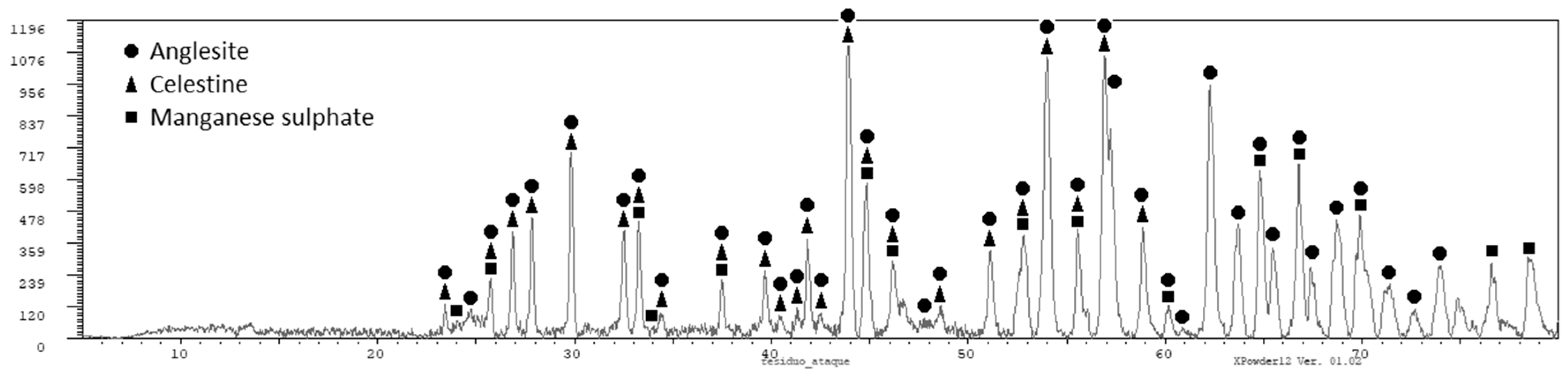
The residue obtained after filtering was analyzed by X-ray diffraction (PANalytical X’Pert Powder, Servicios Científico-Técnicos, Universidad de Oviedo, Oviedo (Asturias), Spain) and the following phases were obtained (see Figure 2, which is consistent with the information provided in Table 2): anglesite (PbSO4) as the main phase, and sulphates of manganese and strontium. Lead is recovered in the solid residue obtained after the filtration as lead sulphate. This lead sulphate could be used in the manufacture of lead [9]. The presence of certain amount of manganese in the solid residue is always unavoidable, as we did not reach a full extraction of manganese. Other impurities also end in the solid residue as calcium, strontium, and potassium, but also silver. The presence of silver and lead in the solid residue of filtration makes it economically interesting. The solution containing most of the manganese (as MnSO4) should be purified before being used to produce electrolytic manganese.
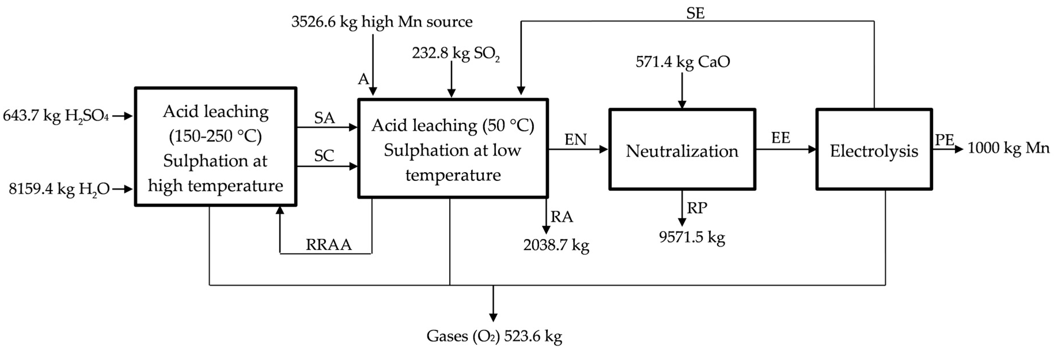
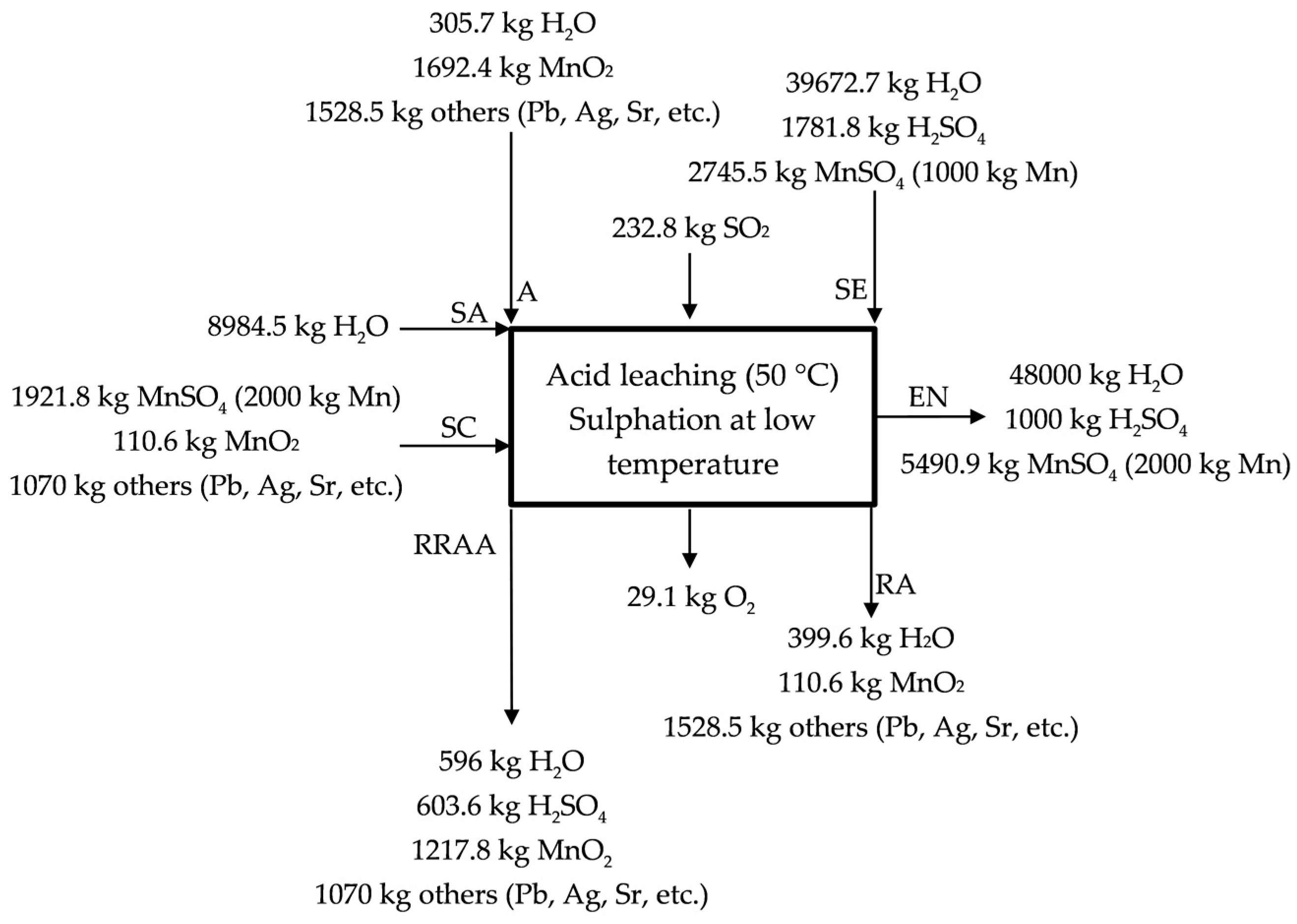
The acid leaching/sulphation at low temperature (50 °C, temperature reached because of the exothermic reactions) is described in Figure 3 for the industrial scale process. The by-product/waste is loaded in a reactor (A, high MnO2 source), where it is leached with SO2 (g) (like that proposed in a laboratory scale but replacing Na2SO3 (s), used in the generation of SO2 (g), by using directly SO2 (g)) (see Equation (5)) and H2SO4 (aq) (see Equation (7)). MnO2 is reduced in presence of both SO2 (g) (20% of the initial manganese, according to Equation (5)) and H2SO4 (aq) (10% of the initial according to Equation (7)) from to , and a solution of MnSO4 (aq) is obtained (a neutralization also happens in this stage as H2SO4 (aq) is used in the lixiviation of the manganese source). The presence of a reducing agent is always necessary for the complete extraction of the manganese, for instance, in the process described by Sanchez-Recio and Sancho [23], they take advantage of the presence of carbon in the powders used as manganese source [23]. The acid solution of MnSO4 (aq) is sent with the MnSO4 (aq) solution obtained in the acid leaching at high temperature (SC, hot sulfated) to neutralization (EN, entrance to neutralization). 70% of the initial manganese is treated in the acid leaching at high temperature (RRAA, recycled residue of acid leaching). The manganese source (anodic lodes and scrapings) contains significant amounts of impurities (lead, strontium, silver, etc.) that leave the process as a product, which we call RA (Residue low MnO2). Most of the impurities enter and leave the process as sulphate so there are not H2SO4 (aq) losses, but ~3.5% Mn is lost in this residue that leaves the process wet. Figure 3 describes the acid leaching at low temperature.
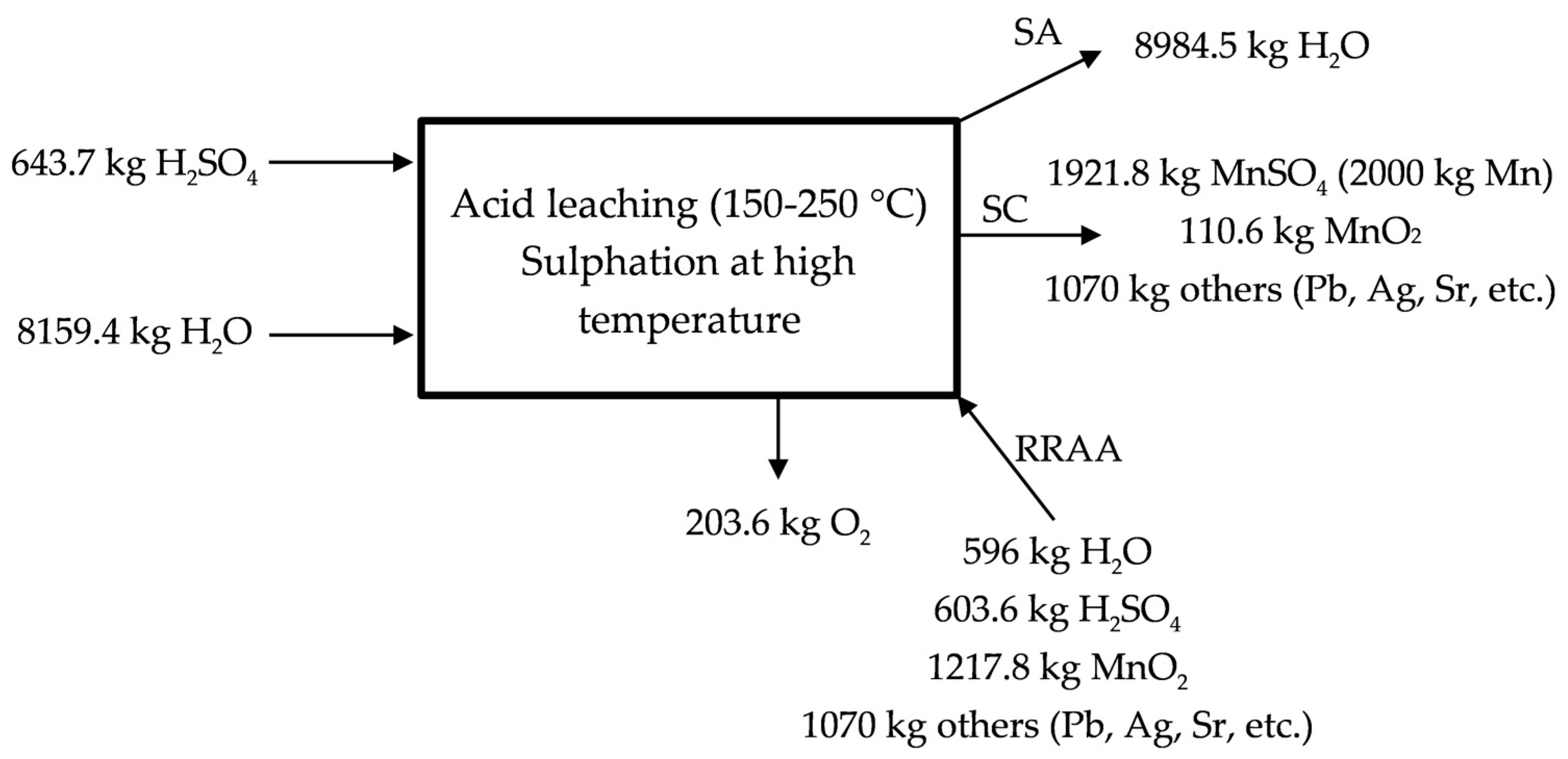
2.2.2. Sulphation at High Temperature (150–200 °C)
The high temperature leaching was also considered in our research project with the idea of recovering all manganese from anodic lodes and scrapings by using a combination of high (70% of the raw material) and low (30% of the raw material) temperature leaching processes. First of all, a study of temperatures, where leaching with carbon and without carbon takes place, was carried out. The reactions that were considered were:
Tests were carried out in thermal balance and it was observed that all of the reactions take place at temperatures below 250 °C, and for that reason experiments were carried out at temperatures of 200 and 225 °C. Other authors worked at higher temperatures [22], but as observed in the thermal analysis, it is not necessary. We have as other variables: milling, the presence of reducing agents and time.
The procedure was: samples were mixed in crucibles (H2SO4 was added with 33% excess with the purpose of facilitating the extraction of manganese as sulphate) and then loaded into the furnace. After that, the samples were heated up to the reaction temperature slowly, and then held at that temperature for the considered time (45 or 60 min). With the purpose of facilitating the removal of the sample from the crucible, crucibles were removed at 100 °C and the product was filtered in presence of water, being the solution analyzed by atomic absorption spectroscopy in order to know the extraction of manganese. The extraction of manganese depending on the conditions is shown in Table 5, Table 6 and Table 7. As in the low temperature leaching, milling increases the extraction of manganese. Extractions would improve with a better control of the furnace temperature avoiding the risks of sulfuric acid evaporation (not pure sulfuric acid was used).
It is observed that increasing the time does not improve the extraction, the same as increasing the temperature. In thermal analysis, it was observed that reactions took place at 200 °C. As happened in low temperature leaching, there were two products after the process: the solid residue containing lead sulphate and other impurities, and the solution containing manganese as MnSO4 to be used in the production of electrolytic manganese (water was added to put MnSO4 in solution, while PbSO4 remained as solid residue because lead sulphate is poorly soluble in water).
The acid leaching at high temperature is described in Figure 4 for the industrial scale proposed process. The process would be like that described in Equation (7), but when considering the industrial scale. It is necessary to supply water and sulfuric acid in this stage to obtain the solution of manganese sulphate. 70% of the initial manganese is lixiviated in this stage by following the reaction presented in the Equation (7). A MnSO4 (aq) solution is sent with the MnSO4 (aq) solution obtained in the low temperature lixiviation to the neutralization process. The residue containing lead, silver, strontium, etc., leaves the process as RA in Figure 1.
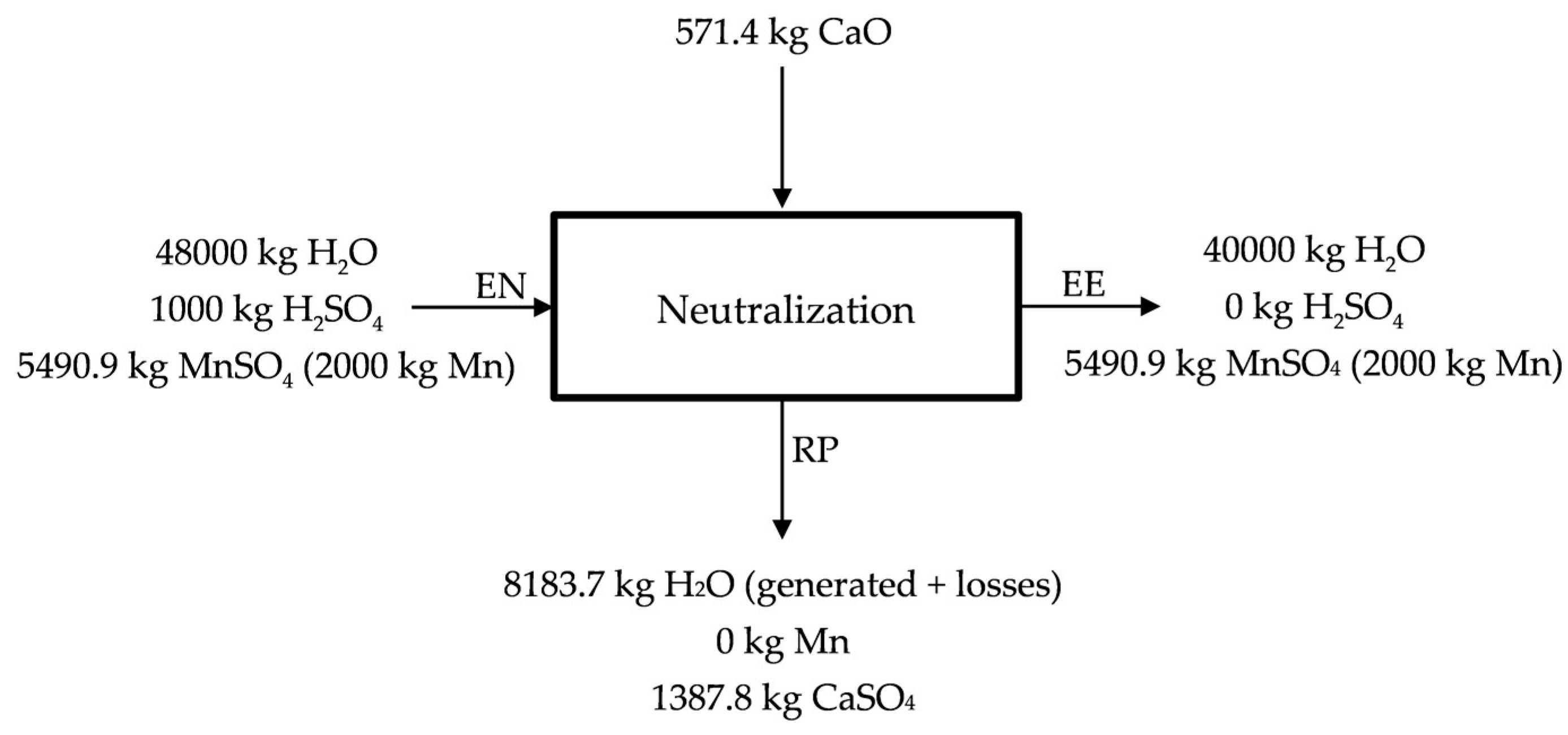
2.2.3. Neutralization with CaO
The objective of the neutralization, apart from the purification of the solution from the elements that could compete with manganese in the electrolytic process, is changing the pH from the acid of the previous stage to the almost neutral that is required in the entrance of the electrolysis process.
Free acidity (pH < 1) is assumed at the entrance of the neutralization process (EN), while at the end of the neutralization pH = 6 is considered (~0 kg free H2SO4) (EE). The neutralization process is described in Figure 5. As neutralizing agent, CaO (s) is used, leaving a residue containing CaSO4 (s) hydrated and most of the impurities (Zn, Co, Cu and Ni) (RP) that could make impure the solution used in the obtaining of manganese by electrolysis. Lime (CaO) is proposed in Figure 5 as neutralizing agent, however, manganese carbonates and even lodes could be used as neutralizing agents. The MnSO4 (aq) solution that is enriched in Mn (50 g Mn/kg H2O) is sent to electrolysis. Part of the water would be recirculated in the process.
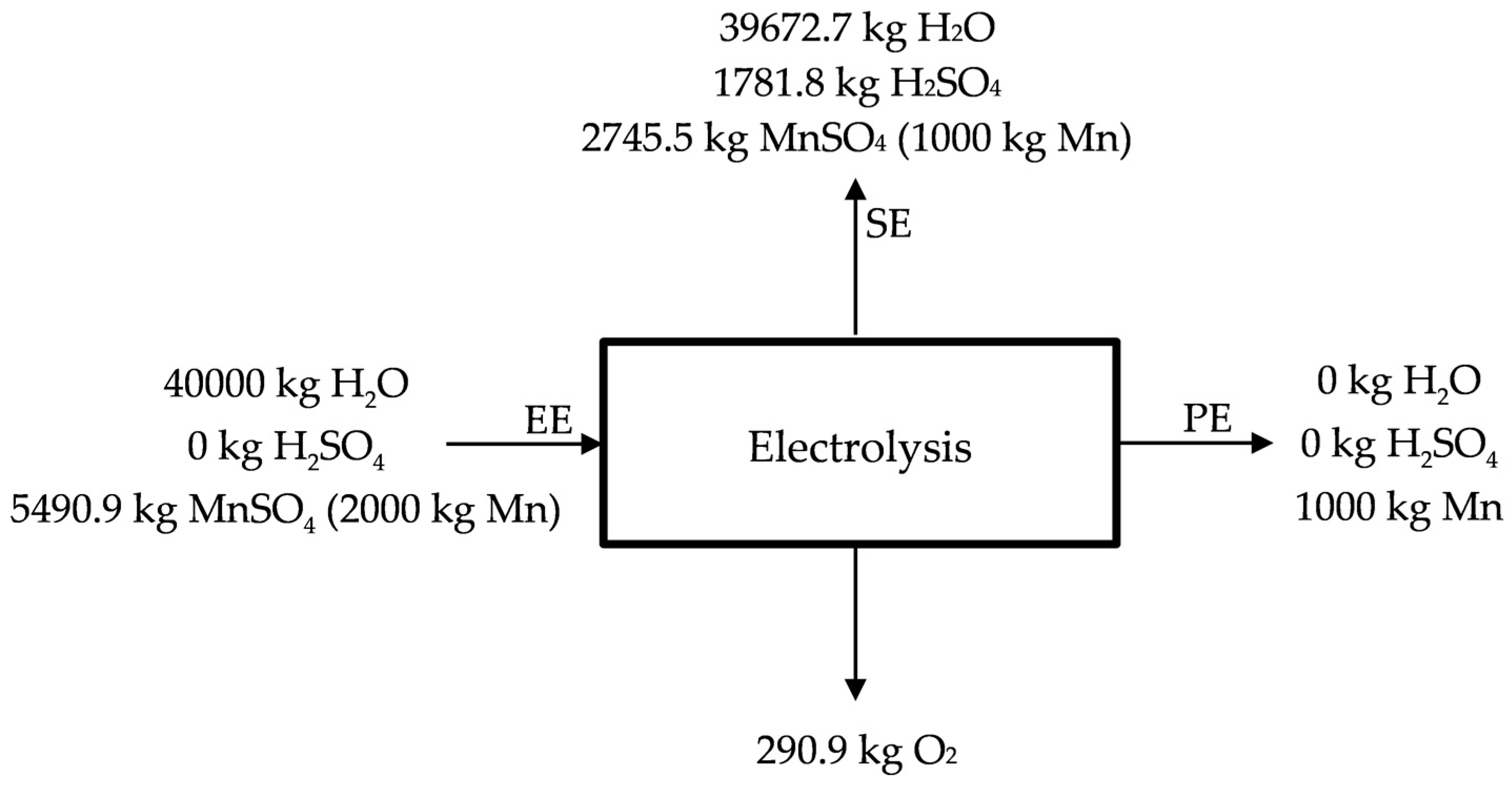
2.2.4. Chemical Purification. Electrolytic Process
The electrolysis process is the final stage for obtaining electrolytic manganese. However, depending on the market conditions, it could be interesting the production of oxide of manganese (IV), oxide of manganese (II), or manganese sulphate, and, for that reason, this stage is optional. Anyway, the process is described in Figure 6.
The reactions involved in the electrolysis process are:
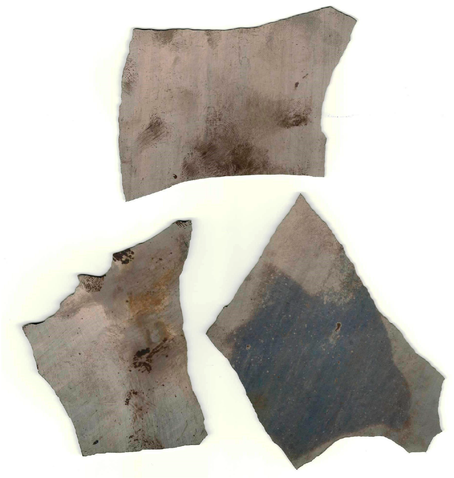
The result of the process is electrolytic manganese (Figure 7), although other products are obtained as it is possible to see in the previous equations (H2SO4, H2O, and O2). H2SO4 and H2O are sent back to the previous stages of lixiviation (SE), the same as the poor liquor (25 g Mn/kg H2O) (see Figure 6) (SE). Manganese deposits on the surface of the cathode as flakes with small amounts of manganese dioxide on the anode (see Figure 7) acting as catalyst [35]. The deposited manganese plate is then removed from the cathode surface by mechanical means, and is prepared to be sold, obtaining manganese qualities of 99.9%. Conditions for the electrolysis process are deeply described by Sánchez-Recio and Sancho [23].
As previously mentioned, several metals are separated in previous stages, for instance, the waste identified as RA in Figure 1 contains most of the lead and the silver present in the initial waste (this residue could be treated with the purpose of recovering both lead and silver). However, certain undesirable metals remain in the solution, and as a consequence, it should be purified before the electrolysis process. The first stage is based on separating several impurities by pH control following the Pourbaix diagrams (potential-pH) keeping the manganese in solution. Iron and aluminum, as well as other less problematic contaminants (such as cobalt and nickel), are removed during this stage. The pH is increased by adding lime to the pulp while it is stirred. The precipitate containing the impurities is separated by filtration. Finally the solution is passed through an active carbon filter.
The second stage of purification is applied to contaminants that cannot be removed by pH control. In this group of contaminants are included those that are nobler than manganese, being the most important the zinc. The removal is achieved by their precipitation as sulphide at slightly acid pH (see that pH at the end of the neutralization process is slightly acid). The problem is the formation of manganese sulphide and for that reason the precipitation requires a sufficient residence time allowing for the manganese sulphide to redissolve, but avoiding the re-dissolution of the other impurities that we wanted to remove.
The introduction in special electrolysis tanks (diaphragm cells, anolyte and catholyte are separated by a membrane) of the purified liquor requires a pH almost neutral and for that reason is conditioned by addition of a base. Finally, the pulp with a manganese concentration of around 30–50 g Mn/L is passed through a crystallizer, where calcium and magnesium are removed as ammonium salts. Ammonium sulphate and hydroxylamine sulphate are added as manganese stabilizer and buffering agent, and antioxidant, respectively. Electrolysis process is carried out in a diaphragm cells with separated anolyte and catholyte. The consumed electrolyte is then recirculated to the process.
The metallic manganese is deposited on the surface of the cathode in the form of flakes (99.9% Mn; 0.015% C; 0.05% S; 0.002% P; 0.001% Ti; 0.004% Mg; 0.006% Fe; 0.004% K; 0.002% Si; 0.003% Ca; 0.004% Zn; 0.001% Cu; 0.002% Co; 0.004% Ni), which is then removed by mechanical means (manganese oxide deposited in the anode acts a catalyst for the desired anodic reaction [35]).
2.2.5. Mass Balance of the Process
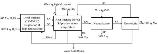
The process that was described in previous pages was summarized in Figure 1. The objective of the process is the obtaining of electrolytic manganese, as shown in Figure 7, from a high manganese source (now considered a waste), such are the anode lodes and scrapings (it could be also applied to other wastes containing high manganese). The amounts of reagents, sub-products, and raw materials are calculated considering 1000 kg of electrolytic manganese at the end of the process produced every day, and the results are supported by the laboratory tests. These amounts are summarized in Table 8, considering an efficiency of the 95% in the recovery of manganese.
3. Discussion
In this paper, we proposed a mixed leaching (low temperature and high temperature) to treat anodic lodes and scrapings from the zinc electrolysis process. The objective of the mixed leaching is taking advantage of the reactivity of the lodes and scrapings facing to sulfuric acid and SO2 in solid solution (low temperature leaching; partial neutralization of the acidity) and achieve a complete the extraction of the manganese by using H2SO4 at high temperature. Even when in the paper, the process could seem divided into four stages independents; in fact, the proposed process would operate in a continuous way. As we see from Section 2.2.2., Sulphation at high temperature, manganese is lixiviated in presence of sulfuric acid without any kind of reducing agent at temperatures of around 200 °C, while from Section 2.2.1., Sulphation at low temperature, we see that manganese extraction is better than in the other case at room temperature (temperature will rise to nearly 50 °C as a consequence of the exothermic behavior of reaction [2]). We also see from the studies of lixiviation at high temperature that the addition of a reducing agent improves the manganese extraction, the same as the milling (the finer the granulometry the higher the manganese extraction). Manganese extractions are more or less two times higher in the presence of carbon or SO2 than those that wer obtained without any kind of reducing agent. For that reason, a combined leaching allows for reaching efficiencies of around 95% in manganese extraction. Better experimental procedure (control of the temperature in the furnace and supply of SO2) would have improved the manganese extractions that are shown in the tables.
Under the premise of a double leaching, a proposal for industrial upscaling was presented for the treatment of anodic lodes and scraping from the zinc electrolysis (this process could be applied in the treatment of other wastes/raw materials, as described in the Section 2.2). Even when the calculations of the main raw materials consumed in the process (water, sulfuric acid, residue and lime) were carried out under the objective of obtaining 1000 kg of electrolytic manganese with recirculation of the sulfuric acid that is generated in the electrolysis, it could be applied in the obtaining of manganese oxide (II), manganese oxide (IV), or manganese sulphate, depending on the market and economic conditions (for instance, high price of the electricity or strong demand of the each one of the manganese products). In that case, the process could be stopped after the mixed leaching (sulfuric acid supply would be increased). The obtaining of manganese oxides (II) and (IV) would be carried out through the following chemical reactions. First of all, manganese is precipitated by using ammonia ():
Ammonium sulphate could be recycled by adding lime (NH3), and manganese hydroxide (II) is obtained. Manganese hydroxide (II) could be roasted, and manganese oxide (II) would be obtained:
And finally, manganese oxide (II) could be oxidized to obtain manganese oxide (IV):
Aluminothermy of the manganese oxides could be performed with the purpose of obtaining metallic manganese (with lower quality than that obtained through the electrolysis process), but that could be used in the aluminum industry.
The treatment of the anodic lodes and scraping would mean for zinc plants an improvement in the competitiveness as the current practice with this material is disposing it in controlled areas with increasing costs. The treatment of this residue implies finishing with the costs of disposing the waste, but it also implies an economic value for the factories, as they will produce a valuable material that could be sold in a market with a strong demand of manganese coming from the steel and aluminum metallurgies. The versatility of the process would allow adapting to the market requirements.
4. Conclusions
Solid residues coming from metallurgical industries are being considered secondary sources of metals in a context of depletion of rich ores and environmental protection awareness. In this way, zinc production by electrowinning produces a waste/by-product of great interest, especially for the manganese industry, known as anodic lodes and scrapings. The interest of this waste/by-product comes from its high manganese content (>30%), and by means of the process that is described in this paper, electrolytic manganese could be obtained. Electrolytic manganese has interest in the aluminum industry (as it provides resistance and ductility to the alloys), in the steel industry (as desulphurizing and fine alloying agent for high performance stainless steels and HSLA (High Strength Low Alloy) steels), in copper and nickel alloys industry and other applications including the production of manganite or zinc-manganese ferrites.
The process described in this paper includes a mixed leaching at low temperature and high temperature, allowing for an optimization of costs and operating conditions (taking advantage of the lodes and scrapings would: reduce costs of storage for this waste; produce an economic impact derived from the sale of the manganese compound (metal, oxide, or sulphate) and the high lead and silver residue; and, optimize the zinc production process as less invaluable products would be generated) for zinc plants. In this way, low temperature lixiviation is supported by the addition of SO2 (g) directly or through Na2SO3 (s) (used in the generation of SO2 (g) as described in the paper), while high temperature lixiviation is based on the lixiviation achieved with H2SO4 at 150–250 °C, as described in the thermal analysis. The combination of both processes allows reaching the almost full leaching of the waste/by-product proposed.
The described process would have special interest for zinc factories, as they are the generators of anodic lodes and scrapings, but also because they produce H2SO4 that is used as a sulphation agent. They would also avoid the cost and dangers of storing this residue in specially prepared places. Economically, the profitability of the process depends on the capacity of the plant, the amortization costs, the electricity price, and electrolytic manganese price.
The described process is considered for anodic lodes and scraping obtained during the zinc electrolysis process, but it could be applied to other wastes/raw materials that we classified in: chemically refractories (low reactivity, slags, powders or other residues coming from the pyrometallurgy of manganese) and reactive (high reactivity, anodic lodes, and scrapings of the zinc electrolysis and manganese carbonates ores). The same as for the raw materials we could talk for the final products, as it would be possible to obtain manganese oxides (MnO and MnO2) and manganese sulphate (MnSO4).
Acknowledgments
The authors want to thank the advices and help of José Pedro Sancho Martínez during the research. We could not forget the valuable information provided by María Teresa Suárez Rodríguez. We thank Juan Carlos Sánchez Recio and Alberto Fuentes for their cooperation during the research. Finally, we want to thank Janusz Prazuch of the AGH University for his help during the research. The research was also supported by the Spanish Ministry of Education, Culture, and Sports via an FPU (Formación del Profesorado Universitario) grant to Daniel Fernández González (FPU014/02436).
Author Contributions
Luis Felipe Verdeja and José Sancho-Gorostiaga designed the work and supervised the experiments. Daniel Fernández-González performed the tests and wrote the manuscript. Juan Piñuela Noval helped in the revision of the manuscript.
Conflicts of Interest
The authors declare no conflict of interest.
References
- Verdeja, L.F.; Sancho, J.P.; Ballester, A.; González, R. Refractory and Ceramic Materials, 1st ed.; Editorial Síntesis: Madrid, Spain, 2014; ISBN 9788490775837. [Google Scholar]
- Fernández-González, D.; Ruiz-Bustinza, I.; Mochón, J.; González-Gasca, C.; Verdeja, L.F. Iron ore sintering: Raw materials and granulation. Miner. Process. Extr. Metall. Rev. 2017, 38, 36–46. [Google Scholar] [CrossRef]
- Fernández-González, D.; Ruiz-Bustinza, I.; Mochón, J.; González-Gasca, C.; Verdeja, L.F. Iron ore sintering: Process. Miner. Process. Extr. Metall. Rev. 2017, 38, 215–227. [Google Scholar] [CrossRef]
- Fernández-González, D.; Ruiz-Bustinza, I.; Mochón, J.; González-Gasca, C.; Verdeja, L.F. Iron ore sintering: Quality indices. Miner. Process. Extr. Metall. Rev. 2017, 38, 254–264. [Google Scholar] [CrossRef]
- Fernández-González, D.; Ruiz-Bustinza, I.; Mochón, J.; González-Gasca, C.; Verdeja, L.F. Iron ore sintering: Environment, automatic and control techniques. Miner. Process. Extr. Metall. Rev. 2017, 38, 238–249. [Google Scholar] [CrossRef]
- Fernández-González, D.; Martín-Duarte, R.; Ruiz-Bustinza, I.; Mochón, J.; González-Gasca, C.; Verdeja, L.F. Optimization of sínter plant operating conditions using advanced multivariate statistics: Intelligent data processing. JOM-J. Miner. Met. Mater. Soc. 2016, 68, 2089–2095. [Google Scholar] [CrossRef]
- Ordiales, M.; Iglesias, J.; Fernández-González, D.; Sancho-Gorostiaga, J.; Fuentes, A.; Verdeja, L.F. Cold agglomeration of Ultrafine Oxidized Dust (UOD) from ferromanganese and silicomanganese industrial process. Metals 2016, 6, 203. [Google Scholar] [CrossRef]
- Chandra, N.; Amritphale, S.S.; Pal, D. Recovery of manganese and lead values from zinc industry anode mud. J. Solid Waste Technol. Manag. 2010, 36, 116–125. [Google Scholar]
- Sancho, J.P.; Verdeja, L.F.; Ballester, A. Metalurgia Extractiva: Procesos de Obtención, 1st ed.; Editorial Síntesis: Madrid, Spain, 2008; Volumen II, pp. 319–375. ISBN 84-7738-803-2. [Google Scholar]
- Bateman, A.M. Geology of zinc deposits. In Zinc the Science and Technology of the Metal, Its Alloys and Compounds, 1st ed.; Mathewson, C.H., Ed.; Reinhold Publishing Corporation: New York, NY, USA, 1959; pp. 36–37. [Google Scholar]
- Ballester, A.; Verdeja, L.F.; Sancho, J. Metalurgia Extractiva. Fundamentos, 1st ed.; Editorial Síntesis: Madrid, Spain, 2000; ISBN 84-7738-802-4. [Google Scholar]
- Zhang, W.; Cheng, Z. Manganese metallurgy review. Part I: Leaching of ores/secondary materials and recovery of electrolytic/chemical manganese dioxide. Hydrometallurgy 2007, 89, 137–159. [Google Scholar] [CrossRef]
- Olsen, S.E.; Tangstad, M.; Lindstad, T. Production of Manganese Ferroalloys, 1st ed.; Tapir Academic Press: Trondheim, Norway, 2007; ISBN 978-82-519-2191-6. [Google Scholar]
- Lu, J.; Dreisinger, D.; Glück, T. Electrolytic manganese metal production from manganese carbonate precipitate. Hydrometallurgy 2016, 161, 45–53. [Google Scholar] [CrossRef]
- Ghafarizadeh, B.; Raschchi, F.; Vahidi, E. Recovery of manganese from electric arc furnace dust of ferromanganese production units by reductive leaching. Miner. Eng. 2011, 24, 174–176. [Google Scholar] [CrossRef]
- Cheng, Z.; Zhu, G.; Zhao, Y. Study in reduction-roast leaching manganese from low-grade manganese dioxide ores using cornstalk as reductant. Hydrometallurgy 2009, 96, 176–179. [Google Scholar] [CrossRef]
- Zhang, Y.; Liu, Q.; Sun, C. Sulfuric acid leaching of ocean manganese nodules using phenols as reducing agents. Miner. Eng. 2001, 14, 525–537. [Google Scholar] [CrossRef]
- Zhang, Y.; You, Z.; Li, G.; Jiang, T. Manganese extraction by sulfur-based reduction roasting-acid leaching from low-grade manganese oxide ores. Hydrometallurgy 2013, 133, 126–132. [Google Scholar] [CrossRef]
- Su, H.; Wen, Y.; Wang, F.; Sun, Y.; Tong, Z. Reductive leaching of manganese from low-grade manganese ore in H2SO4 using cane molasses as reductant. Hydrometallurgy 2008, 93, 136–139. [Google Scholar] [CrossRef]
- Li, C.; Zhong, H.; Wang, S.; Xue, J.; Wu, F.; Zhang, Z. Manganese extraction by reduction-acid leaching from low grade manganese oxide ores using CaS as reductant. Trans. Nonferrous Met. Soc. 2015, 25, 1677–1684. [Google Scholar] [CrossRef]
- Buzatu, M.; Saceanu, S.; Petrescu, M.I.; Ghica, G.V.; Buzatu, T. Recovery of zinc and manganese from spent batteries by reductive leaching in acidic media. J. Power Sources 2014, 247, 612–617. [Google Scholar] [CrossRef]
- Ayala, J.; Fernández, B. Reuse of anode slime generated by the zinc industry to obtain a liquor for manufacturing electrolytic manganese. JOM-J. Miner. Met. Mater. Soc. 2013, 65, 1007–1014. [Google Scholar] [CrossRef]
- Sanchez-Recio, J.C.; Sancho, J. Method of Obtaining Electrolytic Manganese from Ferroalloy Production Waste. U.S.Patent 8,911,611 B2, 4 December 2014. [Google Scholar]
- Pero-Sanz, J.A. Aceros Metalurgia Física, Selección y Diseño, 1st ed.; Editorial CIE Dossat: Madrid, Spain, 2004; ISBN 84-89656-54-1. [Google Scholar]
- Pero-Sanz, J.A.; Quintana, M.J.; Verdeja, L.F. Solidification and Solid-State Transformations of Metals and Alloys, 1st ed.; Elsevier: Amsterdam, The Netherlands, 2017; pp. 255–324. ISBN 978-0-12-812607-3. [Google Scholar]
- Grässel, O.; Krüger, L.; Frommeyer, G.; Meyer, L.W. High strength Fe-Mn-(Al, Si) TRIP/TWIP steels development—Properties—Application. Int. J. Plast. 2000, 16, 1391–1409. [Google Scholar] [CrossRef]
- Frommeyer, G.; Brüx, U.; Neuman, P. Supra-Ductile and High-Strength Manganese-TRIP/TWIP Steels for High Energy Absorption Purposes. ISIJ Int. 2003, 43, 436–446. [Google Scholar] [CrossRef]
- Yang, P.; Xie, Q.; Meng, L.; Ding, H.; Tang, Z. Dependence of deformation twinning on grain orientation in a high manganese steel. Scr. Mater. 2006, 55, 629–631. [Google Scholar] [CrossRef]
- Sipos, K.; Remy, L.; Pineau, A. Influence of austenite predeformation on mechanical properties and strain-induced martensitic transformations of a high manganese steel. Metall. Mater. Trans. A 1976, 7, 857–864. [Google Scholar] [CrossRef]
- Ueji, R.; Tsuchida, N.; Terada, D.; Tsuji, N.; Tanaka, Y.; Takemura, A.; Kunishige, K. Tensile properties and twinning behavior of high manganese austenitic steel with fine-grained structure. Scr. Mater. 2008, 59, 963–966. [Google Scholar] [CrossRef]
- Ordiales, M.; Fernández, D.; Verdeja, L.F.; Sancho, J. Potassium permanganate as an alternative for gold mining wastewater treatment. JOM-J. Miner. Met. Mater. Soc. 2015, 67, 1975–1985. [Google Scholar] [CrossRef]
- Compton, T.R. Battery Reference Book, 3rd ed.; Newnes Reed Educational and Professional Publishing Ltd.: Oxford, UK, 2000; ISBN 978-0-7506-4625-3. [Google Scholar]
- Carosella, M.C.; Culbertson, J.B.; Jacobs, J.H. Electrolytic Manganese. U.S. Patent 2,805,195 A, 3 September 1957. [Google Scholar]
- Tang, Q.; Zhong, H.; Wang, S.; Li, J.; Liu, G. Reductive leaching of manganese oxide ores using waste tea as reductant in sulfuric acid solution. Trans. Nonferrous Met. Soc. 2014, 24, 861–867. [Google Scholar] [CrossRef]
- Wiechen, M.; Berends, H.-M.; Kurz, P. Water oxidation catalyzed by manganese compounds: From complexes to “biomimetic rocks”. Dalton Trans. 2012, 41, 21–31. [Google Scholar] [CrossRef] [PubMed]
Figure 1.
Process used for treating anodic lodes and scrapings from the zinc electrolysis process. SA, exit of acid leaching at high temperature; SC, hot sulfated; RRAA, recycled residue of acid leaching; A, high MnO2 source; SE, exit of electrolysis; EN, entrance to neutralization; RA, residue low MnO2; RP, residue of the neutralization process; EE, entrance to electrolysis; and, PE, product of electrolysis.

Figure 2.
X-ray diffraction pattern for the residue of filtration.

Figure 3.
Description of the acid leaching at low temperature (50 °C).

Figure 4.
Description of the acid leaching at temperatures <300 °C.

Figure 5.
Description of the neutralization stage.

Figure 6.
Manganese electrolytic process.

Figure 7.
Electrolytic manganese flakes.


Table 1.
Compositions of anodic lodes and scrapings from zinc electrolysis process. Determined by X-ray fluorescence (mass %).
Table 1.
Compositions of anodic lodes and scrapings from zinc electrolysis process. Determined by X-ray fluorescence (mass %).
| Mn (%) | O (%) | Pb (%) | S (%) | Ca (%) | Si (%) | Sr (%) | Cd (%) |
| 34.45 | 25.47 | 24.53 | 5.992 | 2.862 | 1.975 | 1.120 | 1.107 |
| Zn (%) | Al (%) | K (%) | Fe (%) | Ag (%) | Cl (%) | Cu (%) | Others (%) |
| 0.9183 | 0.3871 | 0.2803 | 0.2604 | 0.2552 | 0.2064 | 0.1081 | 0.034 |
Table 2.
Compositions of the filtration by-product (mass %). Determined by X-ray fluorescence.
| Pb (%) | O (%) | S (%) | Mn (%) | Sr (%) | Si (%) | Ca (%) | Zn (%) |
| 55.48 | 23.03 | 9.743 | 3.553 | 3.546 | 1.129 | 0.995 | 0.6289 |
| Ag (%) | Al (%) | Fe (%) | Cl (%) | Hg (%) | K (%) | Ba (%) | Others (%) |
| 0.6289 | 0.4730 | 0.2408 | 0.2164 | 0.1191 | 0.09077 | 0.08992 | 0.0682 |
Table 3.
Low temperature process after 30 s milling.
| Test | Na2SO3 | H2SO4 | Mn Extraction (%) |
|---|---|---|---|
| Condition 1 | 25% defect | 11% excess | 10.11 |
| Condition 2 | 15% defect | 18.5% excess | 29.03 |
| Condition 3 | Stoichiometric | 30% excess | 39.82 |
| Condition 4 | 15% excess | 55% excess | 79.92 |
Table 4.
Low temperature process after 90 s milling.
| Test | Na2SO3 | H2SO4 | Mn Extraction (%) |
|---|---|---|---|
| Condition 1 | 25% defect | 11% excess | 55.33 |
| Condition 2 | 15% defect | 18.5% excess | 45.77 |
| Condition 3 | Stoichiometric | 30% excess | 71.04 |
Table 5.
Test carried out at 200 °C for 45 min.
| Test | Mn Extraction (%) |
|---|---|
| After milling 90 s with C | 85.55 |
| Without milling with C | 63.01 |
| After milling 90 s without C | 46.11 |
| Without milling without C | 33.81 |
Table 6.
Test carried out at 200 °C for 60 min.
| Test | Mn Extraction (%) |
|---|---|
| After milling 90 s with C | 55.23 |
| Without milling with C | 58.30 |
| After milling 90 s without C | 38.90 |
| Without milling without C | 33.70 |
Table 7.
Test carried out at 225 °C for 45 min.
| Test | Mn Extraction (%) |
|---|---|
| After milling 90 s with C | 68.60 |
| Without milling with C | 66.10 |
| After milling 90 s without C | 42.80 |
| Without milling without C | 33.70 |
Table 8.
Summary of the amounts of reagents, raw materials and sub-products involved in the industrial process (1000 kg of electrolytic manganese, daily).
Table 8.
Summary of the amounts of reagents, raw materials and sub-products involved in the industrial process (1000 kg of electrolytic manganese, daily).
| Raw Materials | |
| High Mn source: MnO2 waste (~35.5% Mn; ~10% H2O; others (Pb, Sr, etc.), ~50%) (kg) | 3526.6 |
| Reagents | |
| H2SO4 (kg) | 643.7 |
| H2O (kg) | 8159.4 |
| SO2 (kg) | 232.8 |
| CaO (kg) | 571.4 |
| Sub-Products | |
| Residue low MnO2 (~3.5% Mn; ~16.5% H2O; balance others (Pb, Ag, etc.)) (kg) | 2038.7 |
| Residue of neutralization (H2O + CaSO4 + H2SO4) (kg) | 9571.5 |
| Gases (O2 (kg)) | 523.6 |
| Final Product | |
| Electrolytic Mn (kg) | 1000 |
© 2018 by the authors. Licensee MDPI, Basel, Switzerland. This article is an open access article distributed under the terms and conditions of the Creative Commons Attribution (CC BY) license (http://creativecommons.org/licenses/by/4.0/).
Share and Cite
MDPI and ACS Style
Fernández-González, D.; Sancho-Gorostiaga, J.; Piñuela-Noval, J.; Verdeja González, L.F. Anodic Lodes and Scrapings as a Source of Electrolytic Manganese. Metals 2018, 8, 162. https://doi.org/10.3390/met8030162
AMA Style
Fernández-González D, Sancho-Gorostiaga J, Piñuela-Noval J, Verdeja González LF. Anodic Lodes and Scrapings as a Source of Electrolytic Manganese. Metals. 2018; 8(3):162. https://doi.org/10.3390/met8030162
Chicago/Turabian StyleFernández-González, Daniel, José Sancho-Gorostiaga, Juan Piñuela-Noval, and Luis Felipe Verdeja González. 2018. "Anodic Lodes and Scrapings as a Source of Electrolytic Manganese" Metals 8, no. 3: 162. https://doi.org/10.3390/met8030162
Note that from the first issue of 2016, this journal uses article numbers instead of page numbers. See further details here.