Metal Injection Moulding of High Nb-Containing TiAl Alloy and Its Oxidation Behaviour at 900 °C


1
Institute for Advanced Materials and Technology, University of Science and Technology Beijing, Beijing 100083, China
2
Waikato Centre for Advanced Materials, School of Engineering, University of Waikato, Hamilton 3240, New Zealand
3
Shaanxi Hongyuan Aviation Forging Co., Ltd., Xianyang 713801, China
*
Authors to whom correspondence should be addressed.
Metals 2018, 8(3), 163; https://doi.org/10.3390/met8030163
Submission received: 4 February 2018
/
Revised: 25 February 2018
/
Accepted: 3 March 2018
/
Published: 7 March 2018
(This article belongs to the Special Issue Powder Synthesis and Processing)
Abstract
:High Nb-containing TiAl alloy with a nominal composition of Ti-45Al-8.5Nb-0.2W-0.2B-0.02Y (at %) was fabricated by metal injection moulding (MIM) technology with an improved wax-based binder. The critical powder loading and feedstock rheological behaviour were determined. The influence of sintering temperature on microstructures and mechanical properties of the sintered samples and their oxidation behaviour were also investigated. Results showed that a feedstock, with a powder loading of 68 vol % and good flowability, could be obtained by using the improved binder, and oxygen pick-up was lower than that of the sample prepared by using a traditional binder. The ultimate tensile strength (UTS) and plastic elongation of the sample sintered at 1480 °C for 2 h were 412 MPa and 0.33%, at room temperature, respectively. The 1480 °C-sintered sample consisted of γ/α2 lamellar microstructure with the average colony size of about 70 µm, and its porosity was about 4%. The sintered alloy showed better oxidation resistance than that of the cast alloy counterpart.
1. Introduction
TiAl alloys exhibit unique properties, including low density, high specific strength, and excellent oxidation resistance. The combination of those properties makes TiAl attractive for high-temperature applications [1,2,3]. Currently, the latest generation of TiAl alloys with high Nb content (5–10 at %) are considered as candidate structural materials in aerospace and automobile industries [4,5,6] because they exhibit higher oxidation and creep resistance compared with that of conventional TiAl alloys. Unfortunately, the application of these alloys is limited due to poor room-temperature ductility and insufficient oxidation resistance when the working temperature is higher than 900 °C [7]. High Nb-containing TiAl alloys are generally fabricated through the ingot metallurgy method, which is a costly approach, including a multi-step process of vacuum arc melting, annealing, and machining. As a result, an alternative fabrication method for TiAl alloys needs to be developed to reduce the production cost.
Metal injection moulding (MIM) technology is a cost-effective method that can fabricate small components with complex geometry on large scale. In addition, MIM is able to form near-net shaped parts with homogeneous and refined microstructures. In the past few years, the fabrication of Ti alloy parts though MIM technology has been very successful, while only a few works on MIM TiAl alloys have been reported [8,9,10,11,12]. Gerling et al. [10] investigated the MIM process of Ti-47Al-4(Nb, Mn, Cr, Si, B) (at %) alloy, and found that the impurity content of the sintered sample under an argon atmosphere was increased compared to that of vacuum-sintered parts. High impurity content would result in an increase in strength of the sintered materials, while its plastic elongation decreased. Limberg et al. [11] produced Ti-45Al-5Nb-0.2B-0.2C (at %) alloy by metal injection moulding of gas-atomized powder with a wax-based binder. Aluminum evaporation was observed when the samples were sintered under vacuum and the residual porosity of the sintered samples increased proportionally with the applied argon gas pressure. In our previous work [12], Ti-45Al-8.5Nb-(W, B, Y) alloy was fabricated by MIM process, and a relative density could reach 96.2% when the sample was sintered at 1480 °C for 2 h. The ultimate tensile strength and plastic elongation were 382 MPa and 0.46%, respectively. The low level of mechanical properties is mainly attributed to the high impurity content. Contamination is usually a significant concern for producing titanium alloys by MIM, due to the high affinity of titanium to interstitial elements, like oxygen, carbon, and nitrogen [13]. These impurities deleteriously reduce the mechanical properties even when the impurities level is low. Hence, the ASTM F2885-11 standard specification of the minimum content of carbon, oxygen, and nitrogen for MIM-Ti6Al4V components are 0.08 wt %, 0.25 wt %, and 0.05 wt %, respectively. Apart from the selection of a high-quality starting powder, the binder design and debinding techniques are also main technical issues which need to be considered to optimise for reducing impurities contamination [14]. Despite that the traditional binder has been proved to work well, contaminants from the binder are still a big concern for researchers. An improved binder has been developed to minimize impurity contamination and facilitate rapid binder removal. In addition, extensive research on oxidation resistance of TiAl alloys have been carried out, but the reported oxidation data had a large scatter [15], and also few reports are focused on the oxidation behaviour of MIM-processed TiAl alloys.
This study was aimed at preparing high Nb-containing TiAl alloy by the MIM process with an improved wax-based binder. The rheological characteristics of the feedstock and residual impurity content were characterized. The effects of the sintering process parameters on the microstructure and mechanical properties of the sintered alloy were investigated, and the oxidation behaviour of the sintered alloy at 900 °C in the air was also discussed.
2. Experiments
2.1. Materials
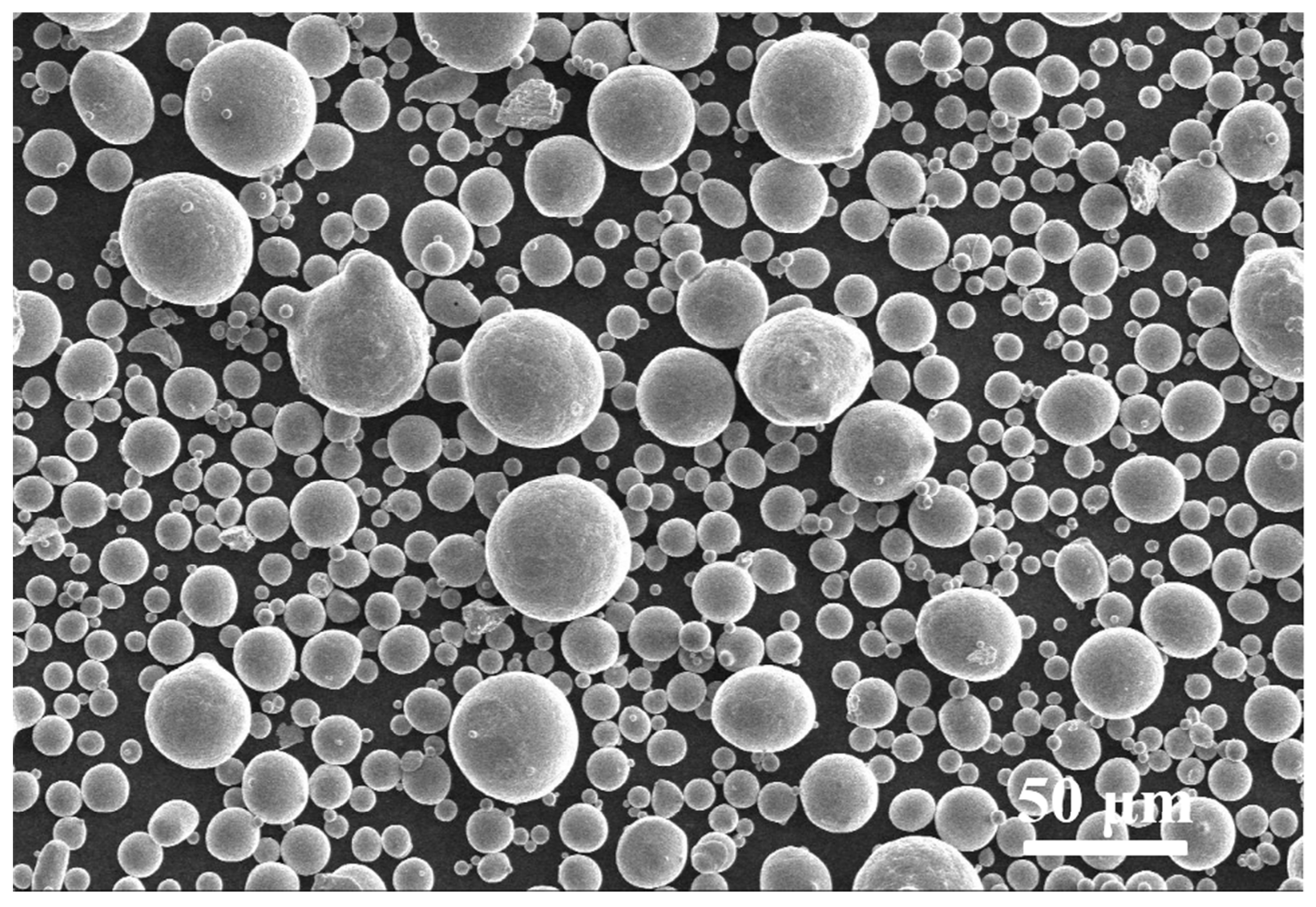
The powder used was gas atomized from a high Nb-containing TiAl alloy ingot with the nominal composition of Ti-45Al-8.5Nb-0.2W-0.2B-0.02Y (at %). The powder preparation details are given in [16]. For injection moulding, the selected powders had a diameter of not larger than 45 μm (d50 = 32 μm). As shown in Figure 1, the powder particles are spherically-shaped and a small number of satellite particles are observed. The used binder system consisted of paraffin wax (PW) and liquid paraffin wax (LPW), as major fillers to control viscosity; polyethylene glycol (PEG) and naphthalene, as leachable components to enhance interaction among binder compositions; polymers polypropylene (PP) and low-density polyethylene (LDPE), as backbone components to give green strength; and stearic acid (SA), as a surfactant and lubricant. The reagents were provided by Sinopharm Chemical Reagent Co., Ltd, Beijing, China. The multiple components of the binder allow for progressive extraction in debinding and were developed based on our long-term studies of the MIM of titanium alloys. For comparison, the traditional binder system (polyethylene, polypropylene, stearic acid, and paraffin wax), which was used in our previous work, was also used for feedstock preparation. The two binders were denoted as F1 and F2 throughout the text. Characteristics of pure components and compositions of binders are listed in Table 1. The composition ranges are presented due to some confidentiality of the binder composition.
2.2. Experimental Procedure
Powder and binder were mixed with different powder loadings (50–73 vol %) in a XSK-160 mixer (Karcher Machinery Co., Ltd., Nanjing, China), at a temperature of 120 °C for 1 h. The feedstock was first granulated and then moulded to form specimens, with dimensions of 35 mm × 20 mm × 6 mm, using a CJ-ZZ50 injection moulding machine (Chen De Plastics Machinery Co., Ltd., Foshan, China). The injection speed and hold time were 95 mm·s−1 and 3 s, respectively. The injection pressure, injection temperature, and mould temperature were 90 MPa, 160 °C, and 45 °C, respectively.
A two-step debinding process was required for removing the binder: (1) the paraffin component was removed in hexane solution at 45 °C for 24 h, and (2) thermal debinding was conducted in the temperature range from 20 to 500 °C under an argon atmosphere. Sintering was carried out under vacuum (10−3 Pa) at the temperature range of 1440 to 1500 °C for 2 h, then the sintered samples were furnace-cooled to room temperature.
2.3. Characterization
The density of the specimens was measured by the Archimedes water immersion method. Microstructural analyses were carried out on a LEO-1450 scanning electron microscope (Zeiss, Oberkochen, Germany) coupled with energy-dispersive X-ray spectroscopy (EDS). The viscosities of the feedstock were measured on an Instron 3211 capillary rheometer (Instron, High Wycombe, UK). The thermogravimetric analysis (TGA) for the sample was conducted on a NETZSCH STA409C machine (Netzsch, Selb, Germany) at a heating rate of 10 °C/min under argon. Oxygen and nitrogen concentration was determined using a Leco TC400 analyser (LECO, St Joseph, MI, USA). The carbon concentration was measured on a Leco CS230 analyser (LECO, St Joseph, MI, USA). Phase constituents were analysed utilizing a Dmax-RB X-ray diffractometer (Cu Kα, λ = 0.15406 nm) (Rigaku, Tokyo, Japan). Tensile tests were conducted at room temperature on an Instron universal test machine at a strain rate of 1 × 10⁻³ s−1. The tensile test specimens were wire-cut into the form of a plate with a gauge size of 25 mm × 3 mm × 1.5 mm using electric discharge machining, and then the specimens’ surface was polished. Three specimens were tested for each condition.
Isothermal oxidation tests were performed at 900 °C in static air for 100 h, and the samples, having a dimension of about 10 × 10 × 3 mm3 were ground using 1200-grit SiC paper, and then ultrasonically cleaned in acetone and dried in air. Each specimen, with the crucible, was weighed before and after oxidation testing with an accuracy of 0.1 mg. A cast alloy with the same chemical composition was employed for comparison. The preparation process of the cast alloy is stated elsewhere [17].
3. Results and Discussion
3.1. Powder Loading and Rheological Behaviour of the Feedstocks
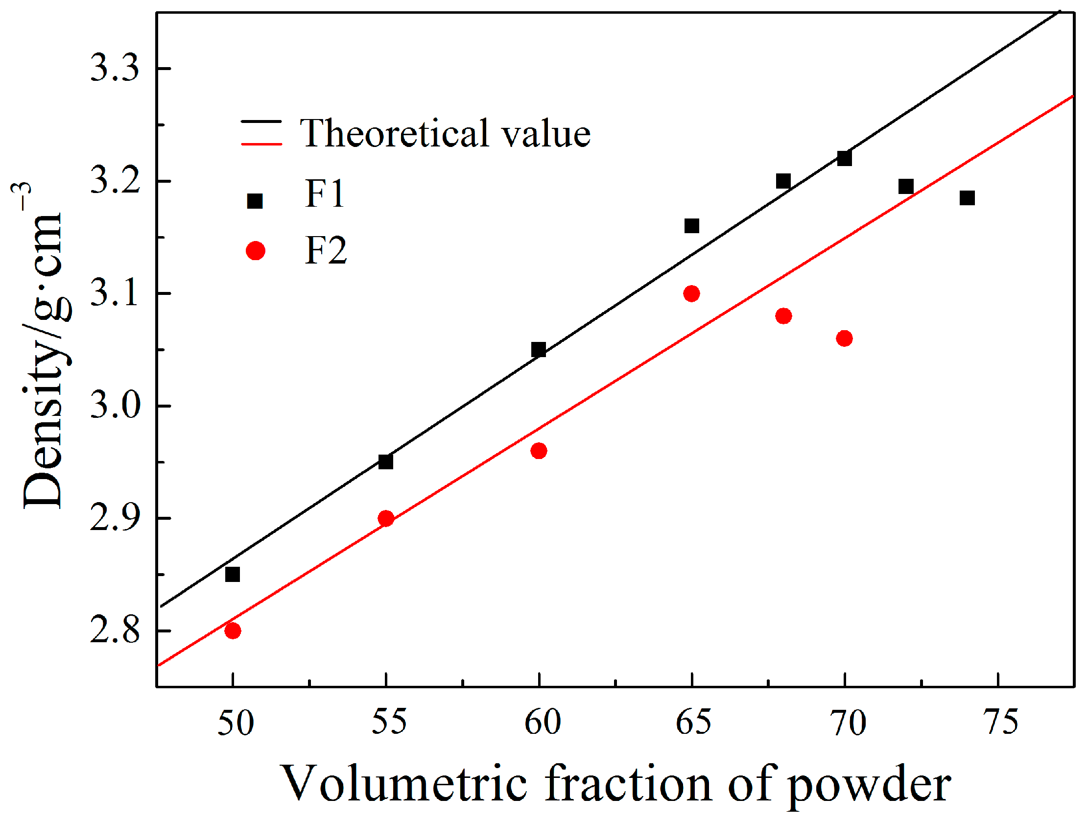
Powder loading represents the volume ratio of powder to the powder-binder mixture. High powder loading helps to enhance sintering and minimize shrinkage. It is well known that there is a critical powder loading which ensures that the binder is just sufficient to form a compact layer on the powder particles and completely fill the intergranular pores [18]. The feedstock becomes stiff and exhibits poor fluidity due to a lower quantity of binder when the powder loading exceeds a threshold value. Figure 2 exemplifies the influence of the powder loading on feedstock density. With increasing the powder loading, the density increases linearly. However, the density is decreased when the powder loading reaches the critical limit. Thus, the critical powder loading is about 70 vol % for binder F1 and 65 vol % for binder F2. According to [19], the optimum powder loading is about 2%–5% lower than the critical powder loading. Thus, the optimum powder loading used in our study is 68 vol % for binder F1 and 63 vol % for binder F2.
For a pseudo-plastic fluid, the general shear rate-dependence of viscosity could be calculated based on the following equation:
where η is the feedstock viscosity, K is a constant, is the shear rate, and n is the flow behaviour index. The value of n indicates the viscosity dependence on the shear rate, which is very important in producing intricate parts. Feedstocks are pseudoplastic fluids and suitable for MIM when n < 1. During the injection molding process, a feedstock with a smaller value of n will show a higher shear sensitivity and hence the viscosity decreases more quickly with increasing shear rate. On a log viscosity versus log shear rate plot, shown in Figure 3, the value of n can be calculated from the plot slope and is listed in Table 2. It can be seen that the viscosity of feedstocks decreased with an increasing shear rate, suggesting both of the feedstocks are pseudoplastic at all testing temperatures. The obtained flow behavior indexes with a minor difference are in the same range that other researchers have reported [14,18,19]. Feedstock F1 exhibits a lower flow behaviour index at all testing temperatures compared to that of Feedstock F2 (Table 2), and this indicates that Feedstock F1 shows a higher shear thinning behaviour.
The effect of temperature on viscosity can be explained by the Arrhenius equation:
where η0 is the viscosity at a reference temperature, R is the gas constant, E is the activation energy, and T is the absolute temperature. A lower value of E suggests a low sensitivity of viscosity to the temperature variation, which reduces the risk of forming defects caused by viscosity changes in the injection molded component. The activation energy can be estimated by fitting the plot of the experimental results with a shear rate of 1066 s−1 (ln η vs. 1/T), as shown in Figure 4. The data show that the value of E is 18.50 KJ/mol for Feedstock F1 and 19.86 KJ/mol for Feedstock F2. This result indicates that Feedstock F1 could be injection moulded in a relatively wider temperature range than Feedstock F2 due to the lower activation energy. The small difference of E between Feedstock F1 and Feedstock F2 has little effect on injection moulding. Flow activation energies of the feedstocks are relatively low and are identified in a suitable range for PIM. These values are similar or lower than those of other feedstocks that have been reported in the literature [14,18,19].
3.2. Binder Decomposition Behavior
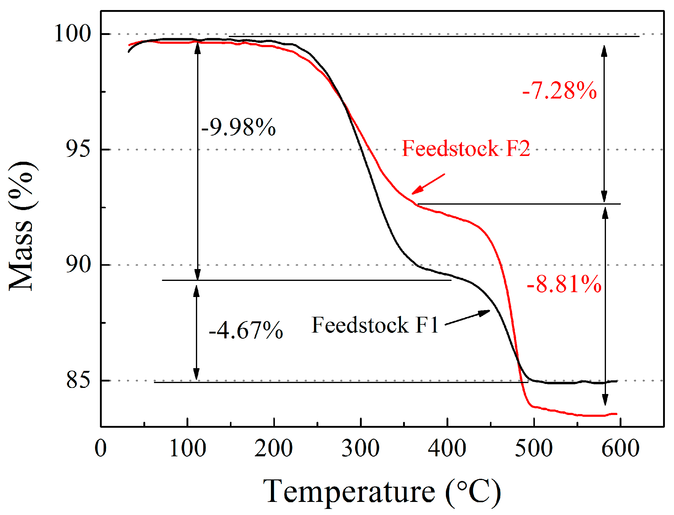
Since the impurities, such as oxygen, nitrogen, and hydrogen, have detrimental effects on titanium alloys, it is required that the pick-up of those impurities during debinding is limited so that the binder is removed completely at a low temperature [20,21]. Figure 5 shows the weight loss of prepared feedstocks under given thermal cycles. The difference of the total weight loss reflects the different powder loadings of the feedstocks. Feedstock F1 with higher powder loading shows a lower mass loss comparing to Feedstock F2. It can be seen that the binders are mainly removed in two stages. For the case of Feedstock F1, the first decomposition stage occurs at about 170 °C and ends about 400 °C because of the loss of PW, PEG, and the evaporation of LPW and naphthalene. Sixty-eight percent of the binder is removed at this stage. The second decomposition stage starts around 400 °C and ends around 500 °C. This is because of the loss of the PP and LDPE. For the case of Feedstock F2, the first decomposition stage occurs at 170 °C and ends around 350 °C, at which 45% of the binder is removed. The second decomposition stage starts at about 350 °C and completes around 550 °C, respectively. The first decomposition stage of Feedstock F1 is completed much quicker than that of Feedstock F2, because the LPW, naphthalene, and PEG are removed continuously at a low temperature. This allows the gaseous products of degradation of the remaining binder to diffuse out of the part though open pore channels generated in the first stage and, hence, is beneficial for the removal of the residual backbone component. In fact, it should be noted that the PW and LPW are removed by solvent extraction in practical terms. With the lower content of the high melting point component PP and LDPE, the weight loss of Feedstock F1 is, as expected, lower than Feedstock F2 during the second stage. This result also leads to a quick removal of the residual component.
Table 3 shows the impurity levels of the raw powder and debound parts. It can be seen that the raw powder shows low impurity levels. During the debinding process, all those three impurities are increased but the increment of the impurities is less in Feedstock F1 compared to Feedstock F2. After debinding, the impurity contents of Feedstock F1 of C, O, and N are 0.04 wt %, 0.13 wt %, and 0.032 wt %, respectively. The low concentrations of those impurities reflect the low contamination during debinding, which enables better control of the impurity levels of the final as-sintered component.
3.3. Phase Analysis and Microstructure
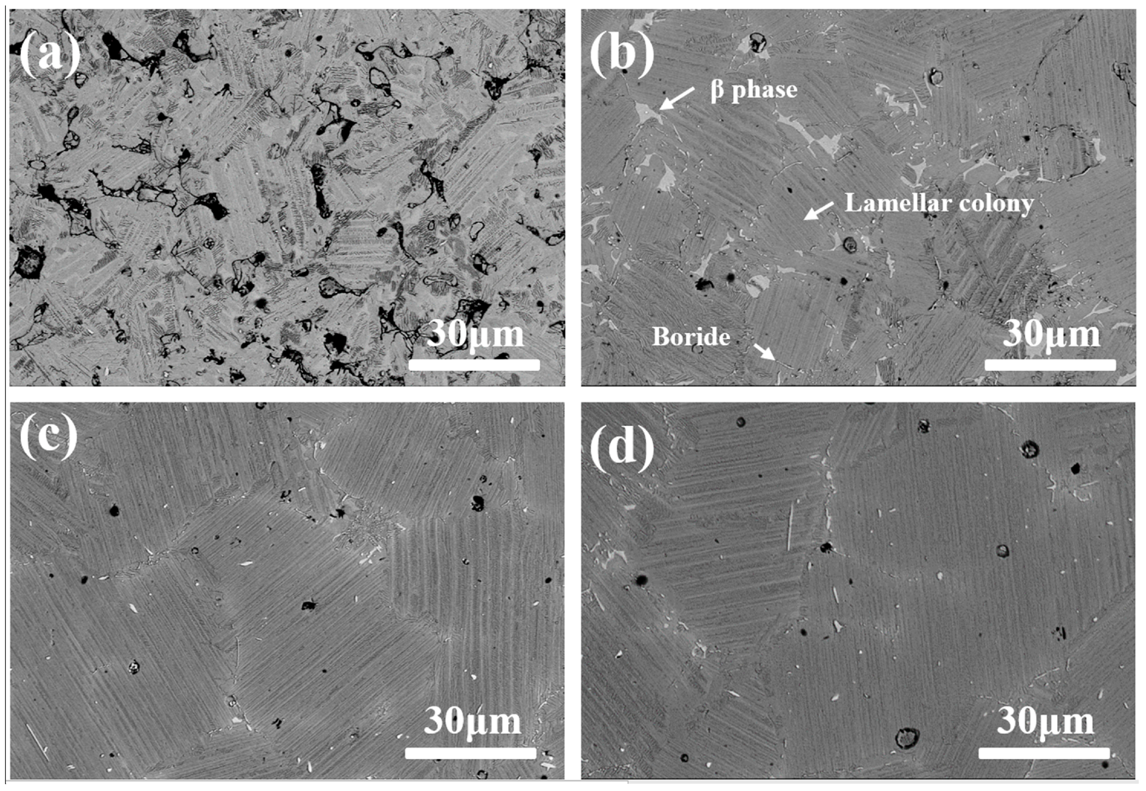
Figure 6 shows the microstructures of the samples made from Feedstock F1 sintered at different temperatures. As shown in Figure 6a, the sample sintered at 1440 °C shows notable sintering necks and the original particles are still visible. When the sintering temperature is increased up to 1460 °C, a nearly fully-dense material is obtained, as shown in Figure 6b. In the meantime, a near lamellar (NL) microstructure is achieved, with a bright-white phase preferentially located at the colony boundaries and triple junctions, which is determined as the β phase by EDS analysis (Table 4). Qualitative EDS analysis also indicates that the white needle-shaped features are titanium borides. A slightly coarser microstructure dominated by lamellar colonies is obtained by sintering at 1480 °C (Figure 6c). The average size of the lamellar colonies is approximately 70 μm and the morphology of the β phase becomes lighter and wider, indicating that the β phase has partly transformed to the α2 and γ phases. A further increase of the sintering temperature to 1500 °C, the lamellar colonies are coarsened (Figure 6d).
Figure 7 shows the XRD patterns of the samples sintered at different temperatures. The clear diffraction peaks suggest that all the specimens consist of a γ-TiAl phase and an α2-Ti3Al phase, and the β phase is only observed for the sample sintered at 1460 °C. The results are consistent with the microstructures observed in Figure 6b.
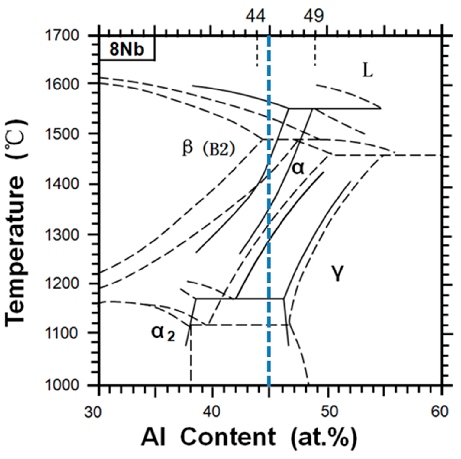
The microstructure of titanium aluminides is very sensitive to the sintering temperature, which is near to the solidus. Slight variations in temperature would change phase transitions during cooling and this will influence the final microstructure. According to the phase diagram (Figure 8) [22], the phase transformation path of the alloy is β → β + α → α → α2 + γ. The segregation caused by the low diffusion rate of Nb and W results in the existence of the β phase. The absence of β phase can be attributed to higher diffusion rate in the high temperature for samples sintered above 1480 °C.
3.4. Mechanical Properties
The results of room temperature tensile tests for the samples sintered at various temperature are listed in Table 5. The tensile properties vary considerably as a function of the temperature when the sintering is below 1480 °C. The ultimate tensile strength increases with increasing of the sintering temperatures from 272 MPa for the sample sintered at 1440 °C to 412 MPa for the sample sintered at 1480 °C. Meanwhile, the elongation shows an increase from 0.15% to 0.33%. This improvement in mechanical properties is related to a drop in porosity (from 7% to 4%), which is in accordance with the microstructure observations. However, for the sample sintered at 1500 °C, the ultimate tensile strength and elongation decrease slightly, and the porosity level is reduced. Generally, higher sintering temperature leads to higher density, which in turn enhances strength and ductility. On the other hand, grain coarsening and oxygen pick-up will also be more important, affecting these properties detrimentally. It is apparent that the positive effects of the lower porosity on mechanical properties have been offset by the negative effects of the colonies growth. This effect is associated with the predominant influence of the coarsening mechanism over densification and investigated by Obasi et al. [23].
It is worth noting that the microstructures of MIM alloys exhibit finer lamellar colony size and without macrosegregation, compared with as-cast alloys. However, the values of the UTS and elongation at room temperature are still lower than those of as-cast alloys and wrought alloys (Table 5). The reasons can be related to the higher oxygen content and higher porosity levels in the MIM alloys comparing to the as-cast alloys counterparts. The sample sintered at 1480 °C has a porosity of 4% and oxygen content of 0.20 wt %, which are much higher than those of cast alloys (~0 and 0.055 wt %). A high sintering temperature generally leads to high impurities pick-up. Apart from the porosity that can be eliminated by hot isostatic pressing (HIP), the high impurity level is a challenge for MIM-TiAl. To obtain better mechanical properties, further improvement is still required to limit the impurity pick-up during the debinding and sintering processes.
3.5. Oxidation Behaviour
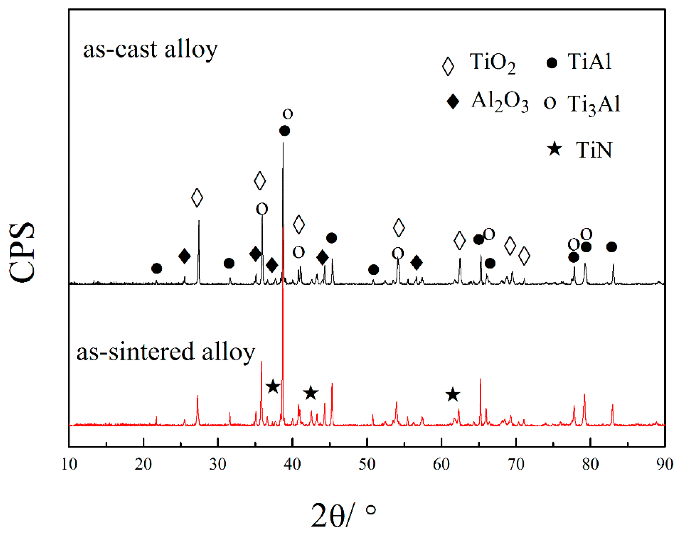
Samples sintered at 1480 °C are used to conduct the oxidation test. Figure 9 shows the microstructure of the as-cast alloy. The alloy exhibits mainly a uniform near-lamellar (NL) structure with a colony size of about 100 μm and retained β phase at colony boundaries and triple junctions is observed. Figure 10 shows the isothermal oxidation kinetics of the alloys at 900 °C in air. The mass changes of the as-sintered alloy and as-cast alloy are 2.46 mg/cm2 and 2.88 mg/cm2, respectively. Oxide scale spallation is not observed in both cases. Figure 11 shows the X-ray diffraction patterns of both as-casted and as-sintered TiAl alloys after oxidation at 900 °C for 100 h. It can be seen that the oxide scales of both alloys are dominated by TiO2, besides a minor amount of α-Al2O3, and a small amount of TiN is observed only in the as-sintered alloy.
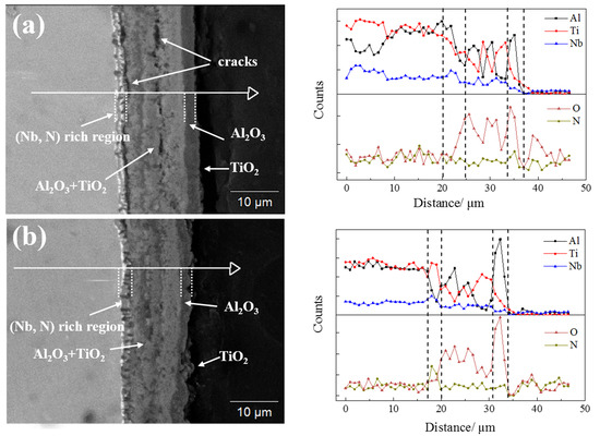
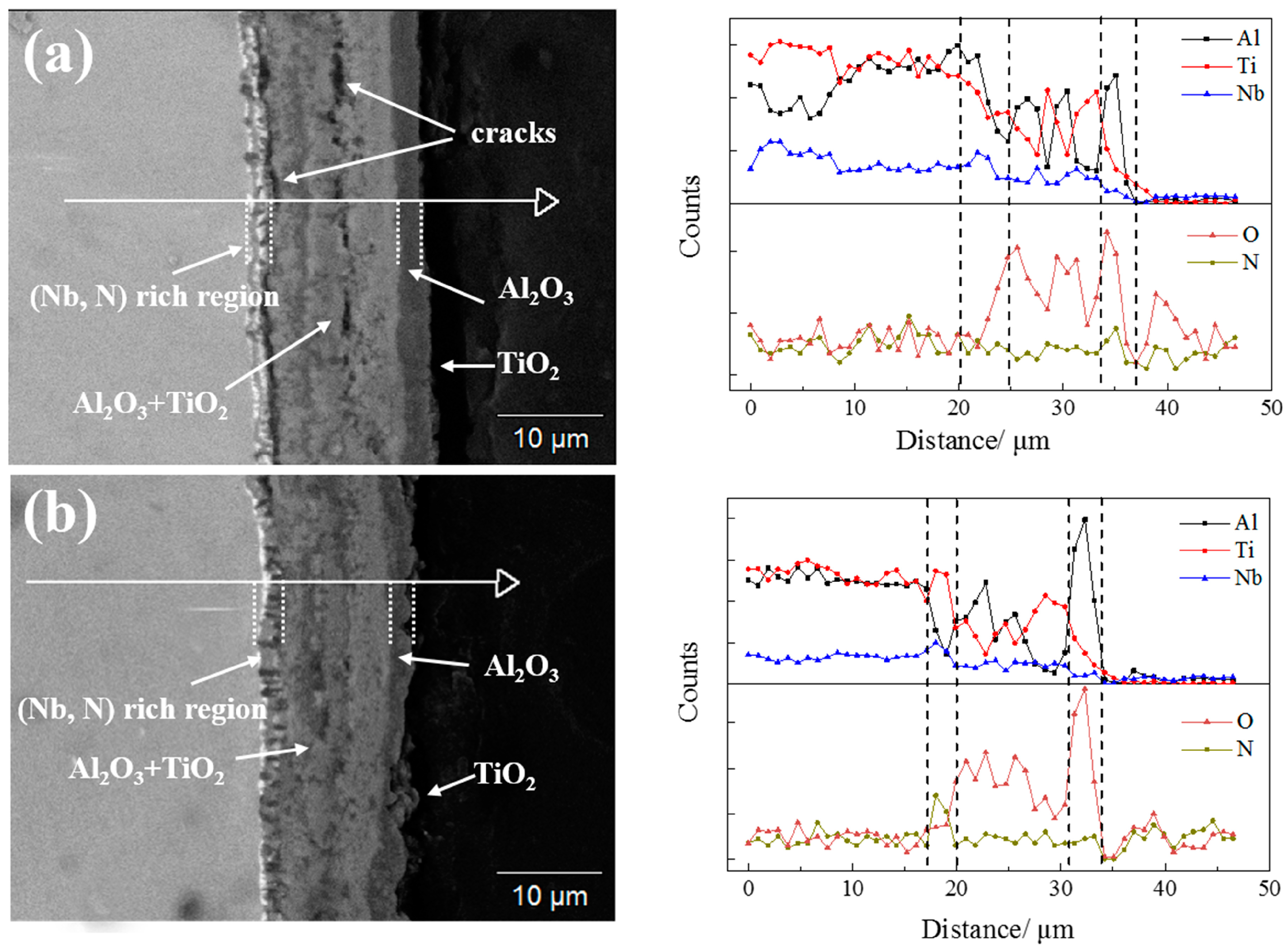
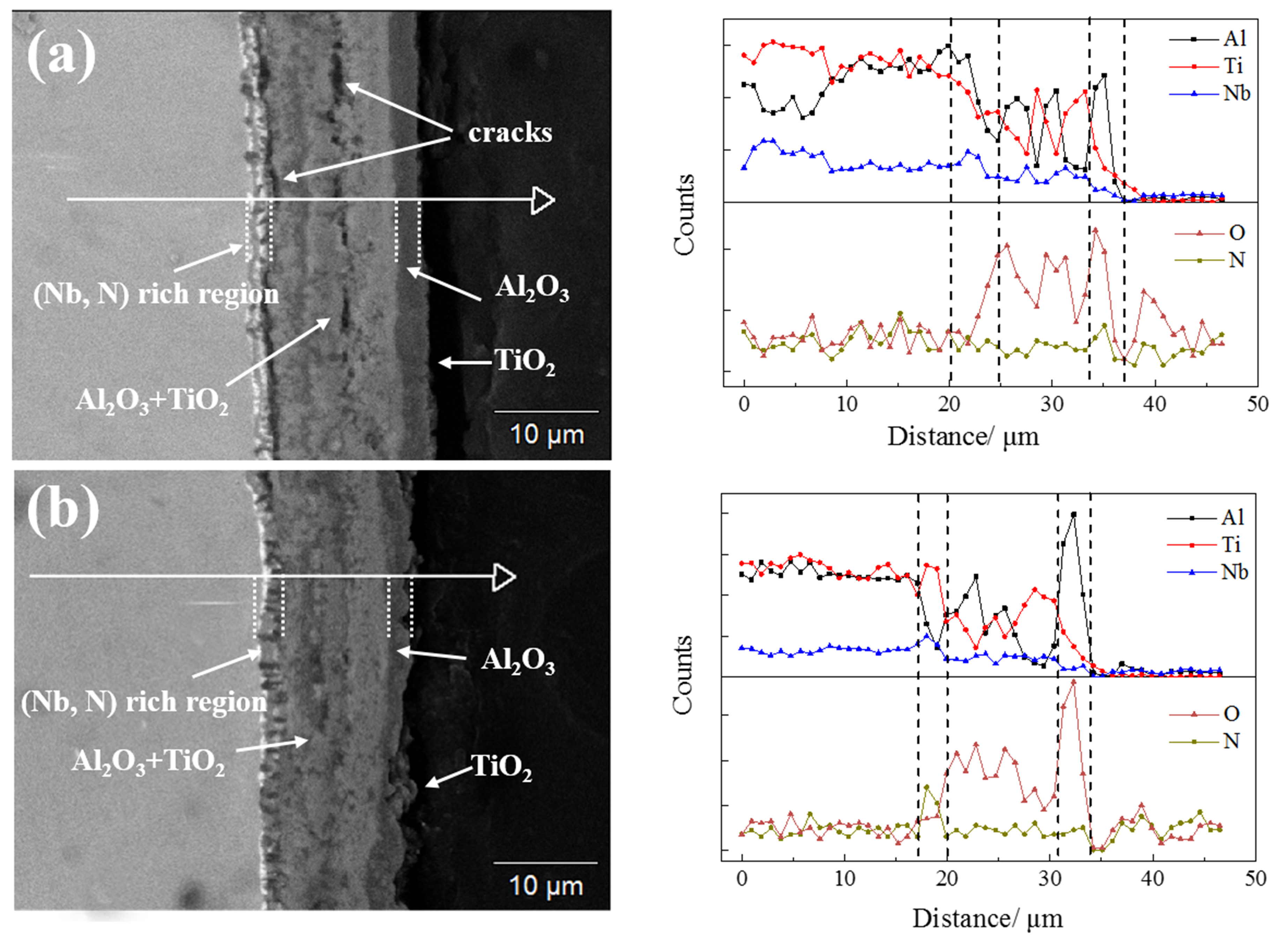
The surface morphologies of the investigated alloys after isothermal oxidation at 900 °C for 100 h are shown in Figure 12. For the as-cast alloy, the specimen surface is covered with large polygon TiO2 grains and fine Al2O3 grains with an irregular shape. For as-sintered alloy, the very fine-grained TiO2 and Al2O3 (~0.5 μm) is presented on the top of the scale, reflecting their low growth rate [7]. Figure 13 shows the cross-section morphologies of the oxide layers of both alloys. EDS line scanning is performed from the base alloy to the outer of oxide scale. It shows the thickness of the oxide scale is about 18 μm for the as-cast alloy and 15 μm for the as-sintered alloy. The cracks are found to form at the oxide scale/alloy interface, resulting in insufficient adherence to the substrate for the as-cast alloy (Figure 13a).
According to XRD and SEM-EDS analysis, it can be inferred that the phase constitution of the oxide scale formed on both alloys is substantially similar. In both cases, the outermost layer of the scale consists of thin and loose TiO2 layer with small amount of Al2O3, the underneath is the thick Al2O3 layer. Mixed metal oxides of Al2O3 and TiO2 are present between the thick Al2O3 layer and (Nb, N)-rich layer next to the alloy substrate. Therefore, the observed result suggests the oxide scale for both alloys is composed of TiO2 layer/Al2O3 layer/mixed TiO2 + Al2O3 layer/(Nb, N)-rich transition layer, from outside to inside, and the result is similar to other reported works [7,26,27]. It is obvious that cracks formed at the scale/alloy interface of the as-cast alloy, which will lead to spallation of the oxide layer and, thus, an enhanced growth rate of the scale.
The results above demonstrate that the as-sintered alloy has a better oxidation resistance than that of the as-cast alloy. Considering the same chemical composition of the alloys, the improved oxidation resistance could be mainly attributable to the compact and adherent oxide scale of the as-sintered alloy. Fine oxide grains can effectively relieve the thermal stress and suppress the crack formation by diffusional plastic deformation [28]. Generally, the deformation rate of the scale decreases with increasing grain size [29]. The as-cast alloy with large gain size cannot tolerate the stress generated in the oxidation process, which results in the formation of cracks. On the other hand, the enrichment of N is more distinct for the as-sintered alloy, as shown in Figure 13b. It has been reported that the layer of TiN can play a role as a barrier against the inward diffusion of oxygen [30]. It is worth mentioning that there is a zone with relatively large grains of Al2O3 caused by internal oxidation and it is close to the as-sintered scale/substrate interface. The insertion of Al2O3 grains to the alloy substrate gives rise to oxygen scale adhesion which in turn, results in better oxygen resistance to the as-sintered alloy. However, Becker et al. [31] reported that the Al2O3 grains have no long-term stability and will dissolve in the further oxidation. The influence of the Al2O3 grains on oxygen resistance is not clear and needs further investigation.
4. Conclusions
Ti-45Al-8.5Nb-0.2W-0.2B-0.02Y alloys were successfully prepared by the MIM process, and the following conclusions can be drawn from the study:
- (1)
- Using the improved binder, a feedstock with powder loading of 68 vol % was obtained. The viscosity of the feedstock accords with the pseudo-plastic behaviour and the flow behaviour index n at 160 °C and activation energy E were 0.547 and 18.50 KJ/mol, respectively.
- (2)
- The improved binder was easier to remove during thermal debinding and the impurity contents of the debound part using an improved binder were lower than those of the traditional binder feedstock.
- (3)
- The 1480 °C-sintered sample consisted of γ/α2 lamellar microstructure with the average colony size of about 70 µm, and its porosity was about 4%. The ultimate tensile strength (UTS) and plastic elongation for the sample sintered at 1480 °C for 2 h were 412 MPa and 0.33%, at room temperature, respectively. The lower levels of ultimate tensile strength and plastic elongation can be related to the higher oxygen content and higher porosity levels in the MIM alloys.
- (4)
- The fine oxide grains of the alloy can effectively relieve the thermal stress and suppress the crack formation during the oxidation process. On the other hand, the presence of a TiN layer plays a role as a barrier against the inward diffusion of oxygen and gives rise to good oxygen scale adhesion. The results mentioned above lead to a better oxidation resistance of the as-sintered alloy than that of the cast alloy counterpart.
Acknowledgments
This research was sponsored by the program of the Beijing Natural Science Foundation (No. 2163053).
Author Contributions
Chengcheng Liu, Xin Lu, and Xuanhui Qu conceived of and designed the experiments; Chengcheng Liu carried out the experiments; Fei Yang, and Zhe Wang analysed the data; Wei Xu contributed reagents, materials, and analysis tools; and Chengcheng Liu wrote the paper under the guidance of Xin Lu and Fei Yang.
Conflicts of Interest
The authors declare no conflict of interest.
References
- Clemens, H.; Mayer, S. Design, Processing, Microstructure, Properties, and Applications of Advanced Intermetallic TiAl Alloys. Adv. Eng. Mater. 2013, 15, 191–215. [Google Scholar] [CrossRef]
- Appel, F.; Clemens, H.; Fischer, F.D. Modeling concepts for intermetallic titanium aluminides. Prog. Mater. Sci. 2016, 81, 55–124. [Google Scholar] [CrossRef]
- Chen, G.; Peng, Y.; Zheng, G.; Qi, Z.; Wang, M.; Yu, H.; Dong, C.; Liu, C.T. Polysynthetic twinned TiAl single crystals for high-temperature applications. Nat. Mater. 2016, 15, 876–881. [Google Scholar] [CrossRef] [PubMed]
- Kothari, K.; Radhakrishnan, R.; Wereley, N.M. Advances in gamma titanium aluminides and their manufacturing techniques. Prog. Mater. Sci. 2012, 55, 1–16. [Google Scholar] [CrossRef]
- Cheng, L.; Chang, H.; Tang, B.; Kou, H.; Li, J. Deformation and dynamic recrystallization behaviour of a high Nb containing TiAl alloy. J. Alloys Compd. 2013, 552, 363–369. [Google Scholar] [CrossRef]
- Appel, F.; Paul, J.D.H.; Oehring, M. Gamma Titanium Aluminide Alloys: Science and Technology; John Wiley & Sons: Weinheim, Germany, 2011. [Google Scholar]
- Park, S.Y.; Seo, D.Y.; Kim, S.W.; Kim, S.E.; Hong, J.K.; Lee, D.B. High temperature oxidation of Ti-46Al-6Nb-0.5W-0.5Cr-0.3Si-0.1C alloy. Intermetallics 2016, 74, 8–14. [Google Scholar] [CrossRef]
- Soyama, J.; Oehring, M.; Ebel, T.; Kainer, K.U.; Pyczak, F. Sintering Behavior and Microstructure Formation of Titanium Aluminide Alloys Processed by Metal Injection Molding. JOM 2017, 69, 676–682. [Google Scholar] [CrossRef]
- Osada, T.; Kanda, Y.; Kudo, K.; Tsumori, F.; Miura, H. High temperature mechanical properties of TiAl intermetallic alloy parts fabricated by metal injection molding. J. Jpn. Soc. Powder Metall. 2016, 63, 457–461. [Google Scholar] [CrossRef]
- Gerling, R.; Aust, E.; Limberg, W.; Pfuff, M.; Schimansky, F.P. Metal injection moulding of gamma titanium aluminide alloy powder. Mater. Sci. Eng. A 2006, 423, 262–268. [Google Scholar] [CrossRef]
- Limberg, W.; Ebel, T.; Pyczak, F.; Oehring, M.; Schimansky, F.P. Influence of the sintering atmosphere on the tensile properties of MIM-processed Ti 45Al 5Nb 0.2B 0.2C. Mater. Sci. Eng. A 2012, 552, 323–329. [Google Scholar] [CrossRef]
- Zhang, H.M.; He, X.; Qu, X.H.; Zhao, L. Microstructure and mechanical properties of high Nb containing TiAl alloy parts fabricated by metal injection molding. Mater. Sci. Eng. A 2009, 526, 31–37. [Google Scholar] [CrossRef]
- Wen, G.; Cao, P. Design Strategy of Binder Systems for Ti Injection Moulding. Key Eng. Mater. 2012, 520, 161–166. [Google Scholar] [CrossRef]
- Hayat, M.D.; Wen, G.; Zulkifli, M.F.; Cao, P. Effect of PEG molecular weight on rheological properties of Ti-MIM feedstocks and water debinding behaviour. Powder Technol. 2015, 270, 296–301. [Google Scholar] [CrossRef]
- Jie, L.; Xiangyi, X. Isothermal Oxidation Behavior of TiAl-Nb-W-B-Y Alloys with Different Lamellar Colony Sizes. Rare Met. Mater. Eng. 2016, 45, 1695–1699. [Google Scholar] [CrossRef]
- Wang, Y.H.; Lin, J.P.; He, Y.H.; Wang, Y.L.; Chen, G.L. Fabrication and SPS microstructures of Ti-45Al-8.5Nb-(W, B, Y) alloying powders. Intermetallics 2008, 16, 215–224. [Google Scholar] [CrossRef]
- Song, L.; Lin, J.; Li, J. Phase transformation mechanisms in a quenched Ti-45Al-8.5Nb-0.2W-0.2B-0.02Y alloy after subsequent annealing at 800 °C. J. Alloys Compd. 2017, 691, 60–66. [Google Scholar] [CrossRef]
- Li, Y.; Li, L.; Khalil, K.A. Effect of powder loading on metal injection molding stainless steels. J. Mater. Process. Technol. 2007, 183, 432–439. [Google Scholar] [CrossRef]
- Rei, M.; Milke, E.C.; Gomes, R.M.; Schaeffer, L.; Souza, J.P. Low-pressure injection molding processing of a 316-L stainless steel feedstock. Mater. Lett. 2002, 52, 360–365. [Google Scholar] [CrossRef]
- Dehghan-Manshadi, A.; Bermingham, M.; Dargusch, M.S.; StJohn, D.H.; Qian, M. Metal injection moulding of titanium and titanium alloys: Challenges and recent development. Powder Technol. 2017, 319, 289–301. [Google Scholar] [CrossRef]
- Baril, E.; Lefebvre, L.P.; Thomas, Y. Interstitial elements in titanium powder metallurgy: Sources and control. Powder Metall. 2011, 54, 183–186. [Google Scholar] [CrossRef]
- Lu, X.; He, X.B.; Zhang, B.; Zhang, L.; Qu, X.H.; Guo, Z.X. Microstructure and mechanical properties of a spark plasma sintered Ti-45Al-8.5Nb-0.2W-0.2B-0.1Y alloy. Intermetallics 2009, 17, 840–846. [Google Scholar] [CrossRef]
- Obasi, G.C.; Ferri, O.M.; Ebel, T.; Bormann, R. Influence of processing parameters on mechanical properties of Ti–6Al–4V alloy fabricated by MIM. Mater. Sci. Eng. A 2010, 527, 3929–3935. [Google Scholar] [CrossRef]
- Xu, X.J.; Lin, J.P.; Wang, Y.L.; Gao, J.F.; Lin, Z.; Chen, G.L. Microstructure and tensile properties of as-cast Ti-45Al-(8-9)Nb-(W, B, Y) alloy. J. Alloys Compd. 2006, 414, 131–136. [Google Scholar] [CrossRef]
- Gao, S.; Xu, X.; Shen, Z.; Ye, T.; Xu, S.; Lin, J. Microstructure and properties of forged plasma arc melted pilot ingot of Ti-45Al-8.5Nb-(W, B, Y) alloy. Mater. Sci. Eng. A 2016, 677, 89–96. [Google Scholar] [CrossRef]
- Lin, J.P.; Zhao, L.L.; Li, G.Y.; Zhang, L.Q.; Song, X.P.; Ye, F.; Chen, G.L. Effect of Nb on oxidation behavior of high Nb containing TiAl alloys. Intermetallics 2011, 19, 131–136. [Google Scholar] [CrossRef]
- Zhao, L.L.; Li, G.Y.; Zhang, L.Q.; Lin, J.P.; Song, X.P.; Ye, F.; Chen, G.L. Influence of Y addition on the long time oxidation behaviors of high Nb containing TiAl alloys at 900 °C. Intermetallics 2010, 18, 1586–1596. [Google Scholar] [CrossRef]
- Lee, D.B. High Temperature Oxidation of TiAl-1.5 wt % Mn-(0, 5, 10) wt % Y2O3 Alloys. Mater. Sci. Forum. 2006, 522, 649–656. [Google Scholar] [CrossRef]
- Jung, H.G.; Kim, K.Y. Effect of a Yttrium Coating on the Oxidation Behavior of Ni3Al (II). Oxid. Met. 1998, 49, 403–430. [Google Scholar] [CrossRef]
- Mitoraj, M.; Godlewska, E.; Heintz, O.; Geoffroy, N.; Fontana, S.; Chevalier, S. Scale composition and oxidation mechanism of the Ti-46Al-8Nb alloy in air at 700 and 800 °C. Intermetallics 2011, 19, 39–47. [Google Scholar] [CrossRef]
- Becker, S.; Rahmel, A.; Schorr, M.; Schütze, M. Mechanism of isothermal oxidation of the intel-metallic TiAl and of TiAl alloys. Oxid. Met. 1992, 38, 425–464. [Google Scholar] [CrossRef]
Figure 1.
Morphology of the gas-atomised Ti-45Al-8.5Nb-0.2W-0.2B-0.02Y powder (sieved fraction <45 μm, d50 = 32 μm).
Figure 1.
Morphology of the gas-atomised Ti-45Al-8.5Nb-0.2W-0.2B-0.02Y powder (sieved fraction <45 μm, d50 = 32 μm).

Figure 2.
Variation in the density of feedstocks with powder loading.

Figure 3.
Plot of the double logarithm of viscosity versus the shear rate at different temperatures.
Figure 3.
Plot of the double logarithm of viscosity versus the shear rate at different temperatures.
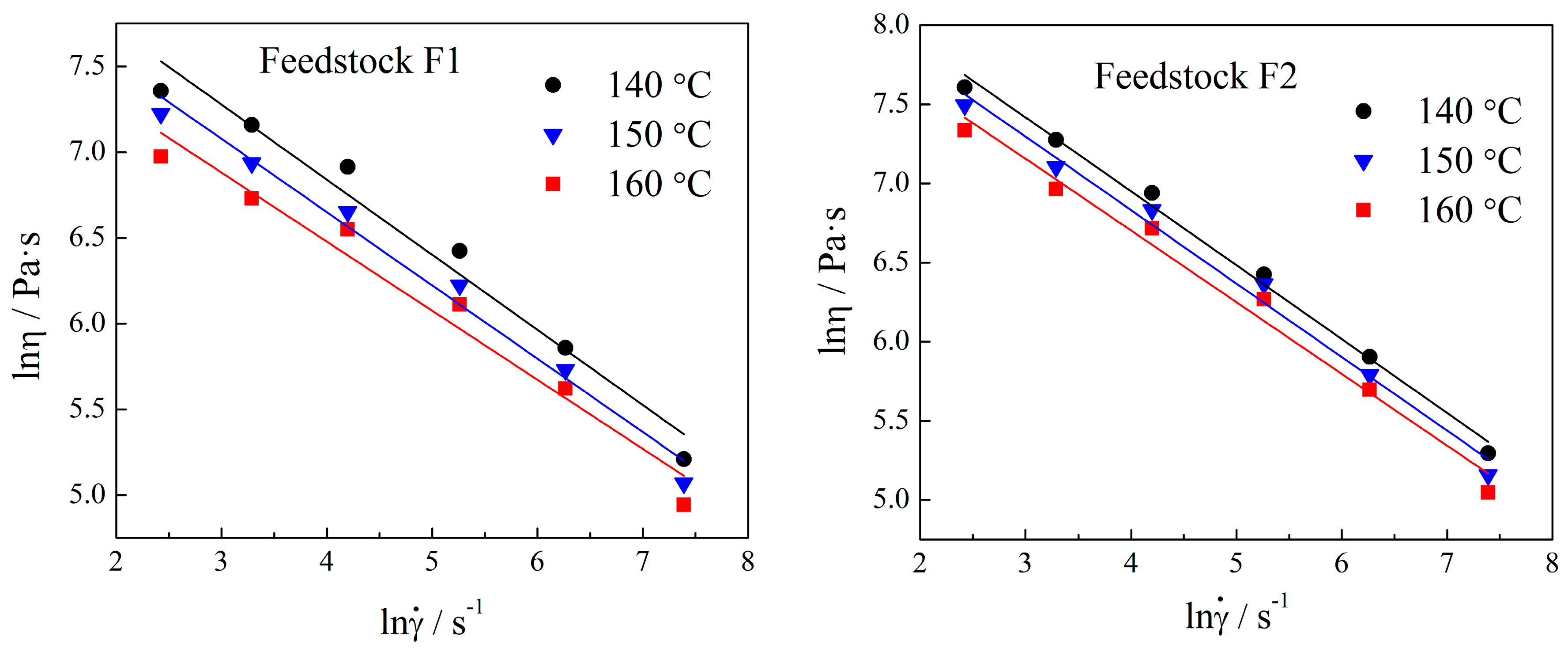
Figure 4.
Temperature dependence of viscosity of the feedstocks.
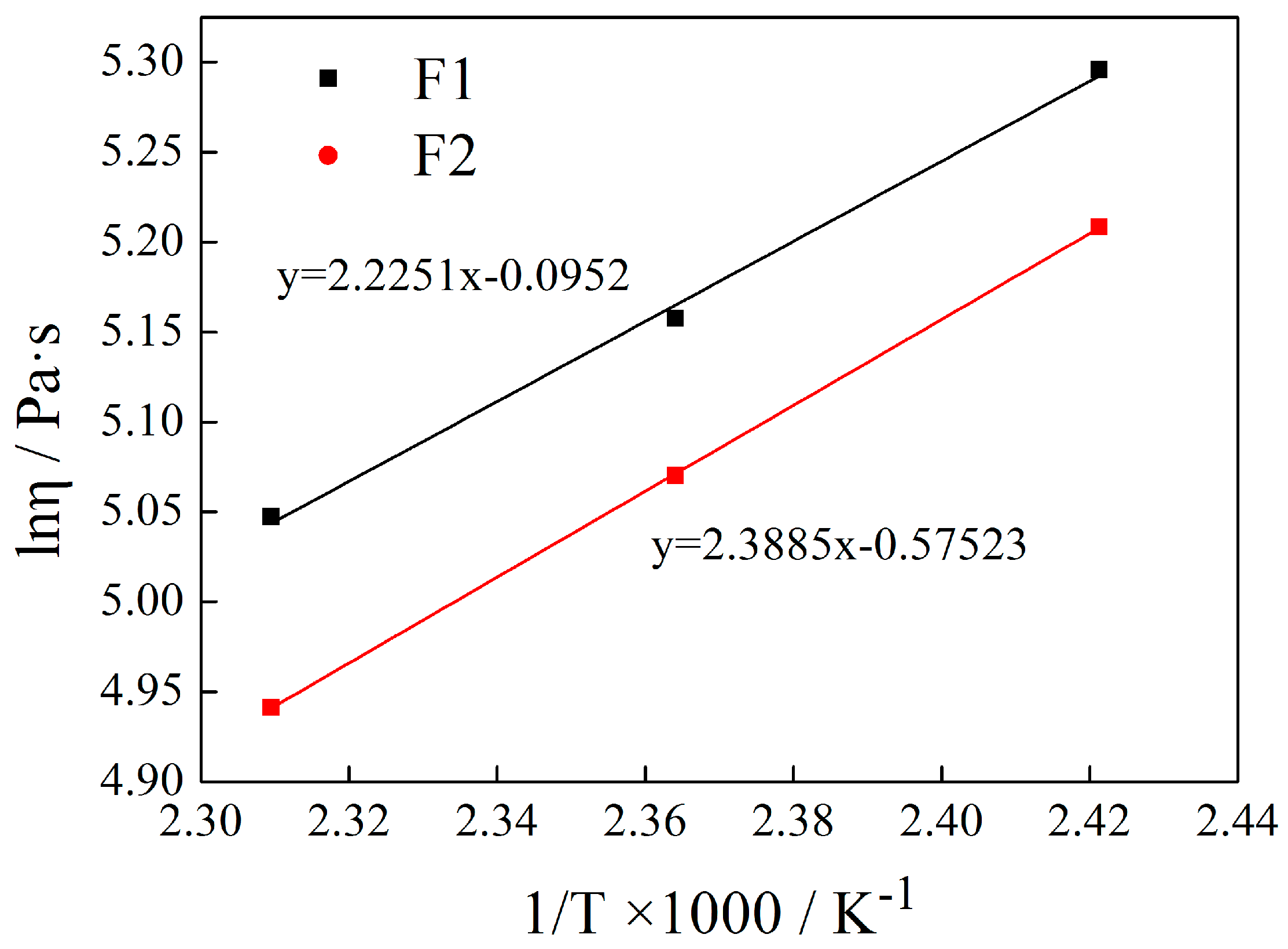
Figure 5.
TGA (thermogravimetric analysis) results of the feedstocks.

Figure 6.
The microstructures of the specimens made from Feedstock F1 sintered at different temperatures: (a) 1440 °C; (b) 1460 °C; (c) 1480 °C; (d) 1500 °C.
Figure 6.
The microstructures of the specimens made from Feedstock F1 sintered at different temperatures: (a) 1440 °C; (b) 1460 °C; (c) 1480 °C; (d) 1500 °C.

Figure 7.
The XRD patterns of the samples sintered at different temperatures.
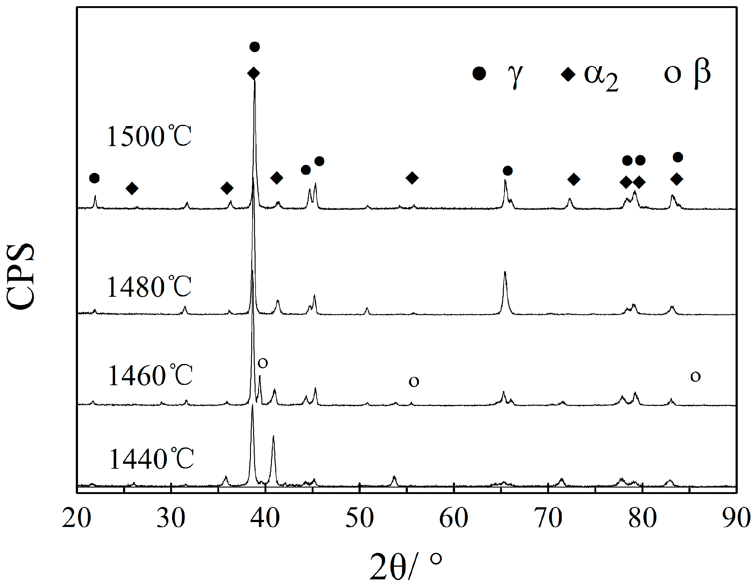
Figure 8.
Phase diagram of Ti-45Al-8Nb. Adapted from ref. [22], with permission from Elsevier, 2009.
Figure 8.
Phase diagram of Ti-45Al-8Nb. Adapted from ref. [22], with permission from Elsevier, 2009.

Figure 9.
The microstructure of the as-cast alloy.
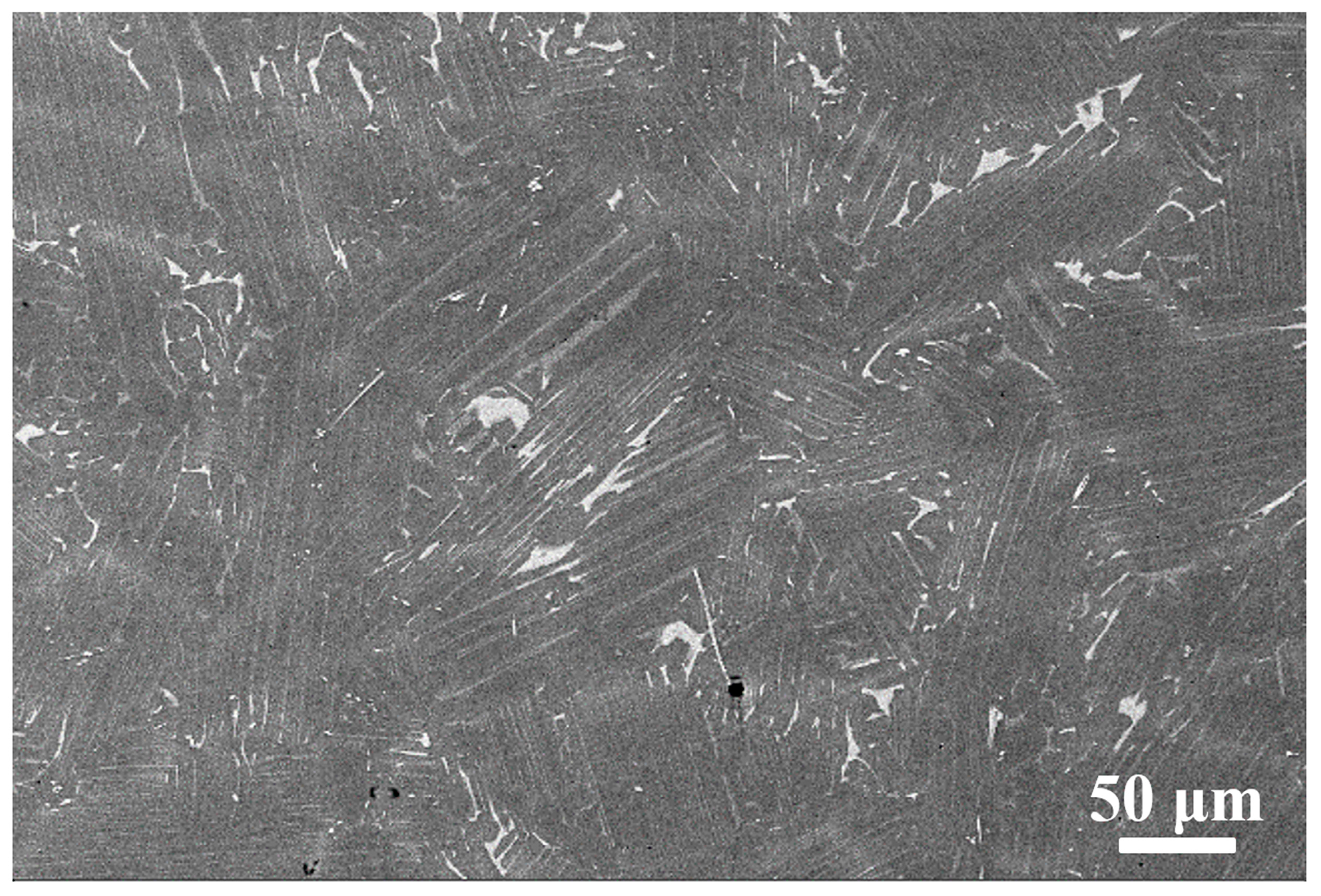
Figure 10.
The isothermal oxidation kinetics of the alloys at 900 °C in air.
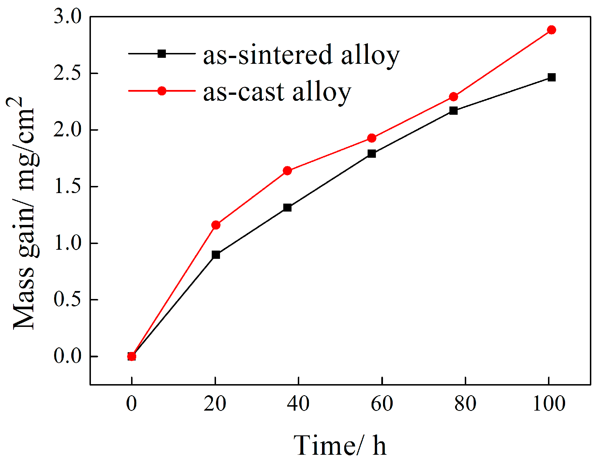
Figure 11.
The X-ray diffraction patterns of both as-casted and sintered TiAl alloys after oxidation at 900 °C for 100 h.
Figure 11.
The X-ray diffraction patterns of both as-casted and sintered TiAl alloys after oxidation at 900 °C for 100 h.

Figure 12.
The micrographs of the surface morphology of the investigated alloys after isothermal oxidation at 900 °C for 100 h, (a) as-cast alloy, (b) as-sintered alloy.
Figure 12.
The micrographs of the surface morphology of the investigated alloys after isothermal oxidation at 900 °C for 100 h, (a) as-cast alloy, (b) as-sintered alloy.
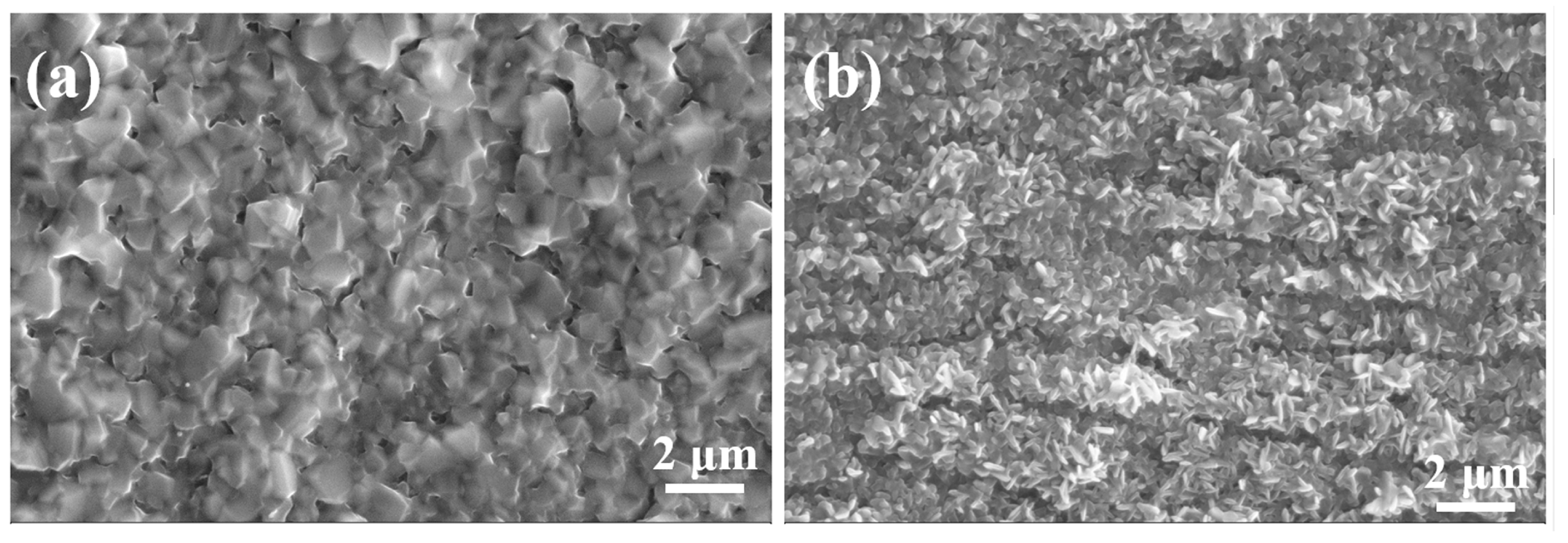
Figure 13.
The cross-section morphologies and EDS line scan profiles of the oxide layers of both alloys after isothermal oxidation at 900 °C for 100 h, (a) as-cast alloy, and (b) as-sintered alloy.
Figure 13.
The cross-section morphologies and EDS line scan profiles of the oxide layers of both alloys after isothermal oxidation at 900 °C for 100 h, (a) as-cast alloy, and (b) as-sintered alloy.

Table 1.
Characteristics of pure components and the compositions of the binders.
| Constituent | PW | LDPE | PP | SA | LPW | PEG-10,000 | Naphthalene |
|---|---|---|---|---|---|---|---|
| Melting point (°C) | 58 | 125 | 142 | 66 | −24 | 65 | 80.5 |
| Degradation temperature (°C) | 200–320 | 170–330 | 250–500 | 170–440 | 170–320 | 160–240 | 180–200 |
| Binder weight (F1) (wt %) | balance | 5–10 | 4 | 5 | 5–9 | 3 | 6–10 |
| Binder weight (F2) (wt %) | 63 | 20 | 12 | 5 | - | - | - |
Table 2.
The n values of feedstocks at different temperatures.
| Temperature (°C) | F1 | F2 |
|---|---|---|
| 140 | 0.5334 | 0.562 |
| 150 | 0.536 | 0.5725 |
| 160 | 0.547 | 0.5972 |
Table 3.
Impurity levels of the raw powder and debound parts.
| Impurity | Raw Powder (wt %) | Debound Parts | |
|---|---|---|---|
| F1 (wt %) | F2 (wt %) | ||
| C | 0.012 ± 0.002 | 0.040 ± 0.003 | 0.055 ± 0.005 |
| O | 0.080 ± 0.01 | 0.130 ± 0.01 | 0.180 ± 0.02 |
| N | 0.021 ± 0.002 | 0.032 ± 0.004 | 0.031 ± 0.005 |
Table 4.
EDS (energy-dispersive X-ray spectroscopy) analysis in Figure 6b.
Table 4.
EDS (energy-dispersive X-ray spectroscopy) analysis in Figure 6b.
| Phases | Ti (at %) | Al (at %) | Nb (at %) | W (at %) | B (at %) |
|---|---|---|---|---|---|
| β phase | 53.28 | 32.73 | 13.46 | 0.53 | - |
| Boride | 19.65 | 11.46 | 5.18 | 0.16 | 63.55 |
| Lamellar colony | 45.51 | 45.74 | 8.75 | - | - |
Table 5.
Tensile properties and porosities of the alloys investigated at room temperature.
| Sintering Temperature | UTS (MPa) | Elongation (%) | Porosity (%) |
|---|---|---|---|
| 1440 °C | 272 ± 5 | 0.15 ± 0.05 | 7 ± 0.3 |
| 1460 °C | 361 ± 3 | 0.26 ± 0.08 | 4.6 ± 0.4 |
| 1480 °C | 412 ± 6 | 0.33 ± 0.06 | 4 ± 0.2 |
| 1500 °C | 383 ± 7 | 0.30 ± 0.05 | 3.8 ± 0.3 |
| As-cast alloy [24] | 668 | 0.49 | ~0 |
| Wrought alloy [25] | 897 | 2.2 | ~0 |
| MIM-ed Ti-45Al-5Nb-0.2B-0.2C (at %) [11] | 630 | 0.2 | <1 |
© 2018 by the authors. Licensee MDPI, Basel, Switzerland. This article is an open access article distributed under the terms and conditions of the Creative Commons Attribution (CC BY) license (http://creativecommons.org/licenses/by/4.0/).
Share and Cite
MDPI and ACS Style
Liu, C.; Lu, X.; Yang, F.; Xu, W.; Wang, Z.; Qu, X. Metal Injection Moulding of High Nb-Containing TiAl Alloy and Its Oxidation Behaviour at 900 °C. Metals 2018, 8, 163. https://doi.org/10.3390/met8030163
AMA Style
Liu C, Lu X, Yang F, Xu W, Wang Z, Qu X. Metal Injection Moulding of High Nb-Containing TiAl Alloy and Its Oxidation Behaviour at 900 °C. Metals. 2018; 8(3):163. https://doi.org/10.3390/met8030163
Chicago/Turabian StyleLiu, Chengcheng, Xin Lu, Fei Yang, Wei Xu, Zhe Wang, and Xuanhui Qu. 2018. "Metal Injection Moulding of High Nb-Containing TiAl Alloy and Its Oxidation Behaviour at 900 °C" Metals 8, no. 3: 163. https://doi.org/10.3390/met8030163
Note that from the first issue of 2016, this journal uses article numbers instead of page numbers. See further details here.