Article

Failure Analysis of PHILOS Plate Construct Used for Pantalar Arthrodesis Paper I—Analysis of the Plate

1
Boonshoft School of Medicine, Wright State University, Dayton, OH 45435, USA
2
Department of Biomedical, Industrial, and Human Factors Engineering, Wright State University, Dayton 45435, OH, USA
3
Materials Characterization Facility, UES Inc., 4401 Dayton-Xenia Road, Beavercreek, OH 45432, USA
4
Department of Orthopedic Surgery, Sports Medicine and Rehabilitation, Wright State University, Dayton, OH 45435, USA
*
Author to whom correspondence should be addressed.
Metals 2018, 8(3), 180; https://doi.org/10.3390/met8030180
Submission received: 21 December 2017 / Revised: 5 March 2018 / Accepted: 8 March 2018 / Published: 13 March 2018
(This article belongs to the Special Issue Failure Analysis of Biometals)

Abstract

:
The failure of a proximal humerus internal locking system (PHILOS) used in a pantalar arthrodesis was investigated in this paper. PHILOS constructs are hybrids using locking and non-locking screws. Both the plate and the screws used in the fusion were obtained for analysis. However, only the plate failure analysis is reported in this paper. The implant had failed in several pieces. Optical and scanning electron microscopic analyses were performed to characterize the failure mode(s) and fracture surface. The chemical composition and mechanical properties of the plate were determined and compared to controlling specifications to manufacture the devices. We found that equivalent tensile strength exceeded at the locations of high stress, axial, and angular displacement and matched the specification at the regions of lower stress/displacement. Such a region-wise change in mechanical properties with in vivo utilization has not been reported in the literature. Evidence of inclusions was qualitatively determined for the stainless steel 316L plate failing the specifications. Pitting corrosion, scratches, discoloration and debris were present on the plate. Fracture surface showed (1) multi-site corrosion damage within the screw holes forming a 45° maximum shear force line for crack-linking, and (2) crack propagation perpendicular to the crack forming origin that may have formed due to the presence of inclusions. Fracture features such as beach marks and striations indicating that corrosion may have initiated the crack(s), which grew by fatigue over a period of time. In conclusion, the most likely mechanism of failure for the device was due to corrosion fatigue and lack of bony in-growth on the screws that may have caused loosening of the device causing deformity and pre-mature failure.

1. Introduction

Arthrodesis has served as a standard treatment for painful arthritis of the ankle and the subtalar joints. The ankle joint is composed of the tibia and fibula and the subtalar joint includes the talus and calcaneus [1]. Fusion of the ankle, subtalar, and talonavicular joints together is known as pantalar arthrodesis and has been performed by orthopaedic surgeons since 1906 [2]. There also are non-surgical treatment methods such as non-steroidal anti-inflammatory medications and prefabricated or custom orthotics, but these methods are not effective in all patients.
Pantalar arthrodesis can be achieved with internal or external fixation. Internal fixation is preferred in most cases as it has many advantages over external fixations. The incidence of non-unions and mal-unions are reduced with internal fixation [3]. Implants that can be used for internal fixation are plates, screws, intramedullary nails, and wires. Locking compression plates (LCP) are advantageous when compared to others since they provide an angular-stable interface. LCPs are most commonly used for acute traumatic fractures, osteotomy fixation, non-union repair, and arthrodesis [4]. In the compression plating technique with conventional screws, primary stability is achieved by the compression between the plate and the bone. However, since there is no direct contact between the plate and the bone, the primary stability achieved by compression may be lost due to cyclic loading. The two major mechanisms for fixation failure in these constructs are axial tilting in the absence of the normal support given by bone due to fracture comminution and screw loosening in osteoporotic bone. In these cases, locking screws are preferred to conventional screw to limit these mechanisms of failure. Because locking screws lock into the locking plate, the amount of axial tilt and screw loosening is minimized. Proximal humerus internal locking system (PHILOS) (Figure 1) plating used in the pantalar joint utilizes the benefit that blood supply to the bone is preserved and soft-tissue injury minimized due to lack of compression. In addition, successful fixation result in anatomic reduction, stable fixation, preservation of blood supply, and early mobilization [5,6,7,8,9] which occur with the use of locking compression technology.
A summary of device failures was compiled from literature [10,11,12,13,14,15,16,17,18,19,20,21,22,23] (see Appendix A). It identifies the devices, material of construction, failure modes and other fracture features. It is noteworthy that this may be the only case involving the failure analysis of PHILOS (Figure 1). A number of studies involving SS316L material revealed inclusion sites as crack origins [10,15,16,17,18], corrosion, wear and fatigue [10,11,12,13,15,16,18,19,21,23] with no visible mechanical failure yet having failed clinically [12,14]. The majority of the devices were constructed with SS 316 and 316L; however, a few devices constructed with Ti-6Al-4V alloy [19,20,21,22] and pure titanium [23] were also found. From this summary it is prudent to investigate the chemical composition and inclusions that form pitting and corrosion fatigue related failures of the devices.

1.1. Case Presentation (Clinical Summary)

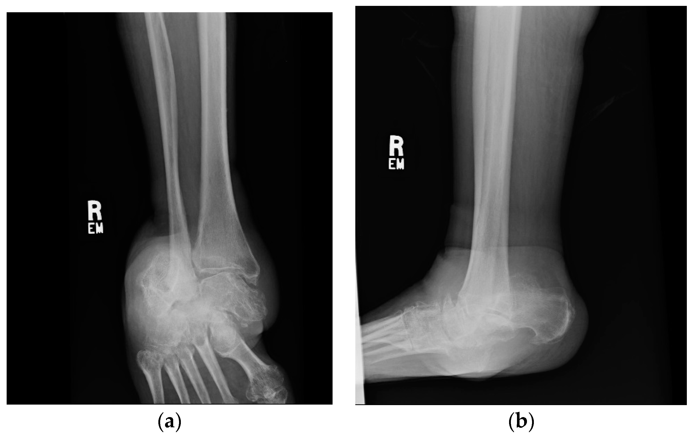
1.1.1. Initial Presentation

A 68-year-old female was seen in the office for a right foot deformity. She experienced changes in ambulation over the past month with no history of trauma. Other than her progressive ankle deformity, she was relatively healthy.
On physical exam there was a fixed, non-reducible deformity of the right ankle. Palpable posterior tibial and dorsalis pedis pulses were present. Sensation over the dorsal and plantar foot was intact to light touch. Initial ankle X-rays were significant for a right ankle deformity consistent with chronic lateral subtalar dislocation with varus tibiotalar joint alignment (Appendix B, Figure A1 and Figure A2). There was no evidence of bone loss or acute fracture. It was determined that the patient required a right ankle pantalar arthrodesis.

1.1.2. Operation

A 3.5 mm LCP PHILOS (Synthes, Solothurn, Switzerland) was inverted so that the locking screws could be inserted into both the talus and calcaneus and compression screws into the tibia. The plate was fixed to the lateral portion of the calcaneus and tibia using four 3.5 mm cortical screws proximally in the tibia and seven 3.5 mm locking screws distally. A 6.5 cannulated screw (Zimmer, Warsaw, IN, USA) was placed from the tibia across the talus and into the calcaneus to provide compression across the tibiotalar and subtalar joints. Three additional 3.5 mm screws with washers were placed from the navicular into the talus in order to fuse the talonavicular joint.
An additional 3.5 mm screw and washer were inserted from the anterior process of the calcaneus to the cuboid to achieve fusion at this joint. The patient was to remain non-weight bearing on her surgical extremity for three months.

1.1.3. Post-Operative Follow-Up

Clinically, in the first year of follow up appointments, the patient was doing very well. Weight bearing as tolerated began after three months. She returned to the surgeon’s office once yearly for follow up. During every follow up, new imaging (by X-ray) of the ankle was obtained. Imaging over this time showed that her ankle did not fuse and formed a non-union. Her hardware failed as seen with radiographic evidence of breakage. The hardware breakage progressed from a single screw to involving multiple screws and the plate over the post-operative course. At six years post-operative she complained of a new onset pain in her operative ankle. With the new onset symptoms and evidence of failed fusion and hardware failure, a removal of hardware and revision ankle fusion was planned.

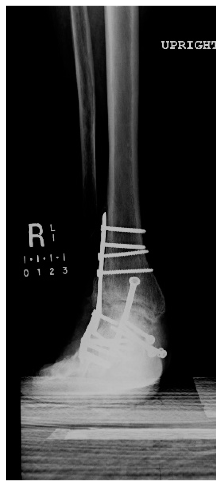
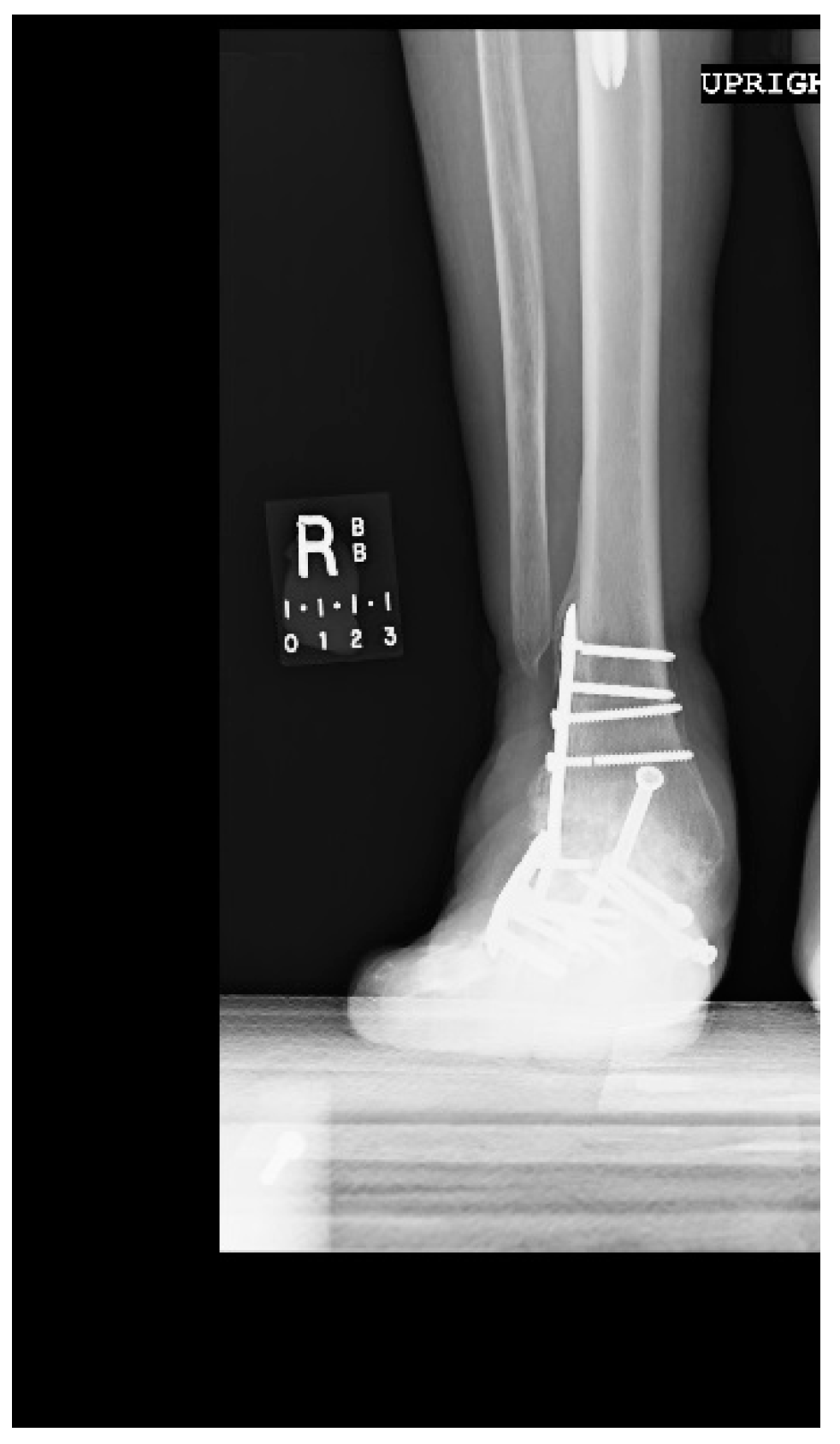
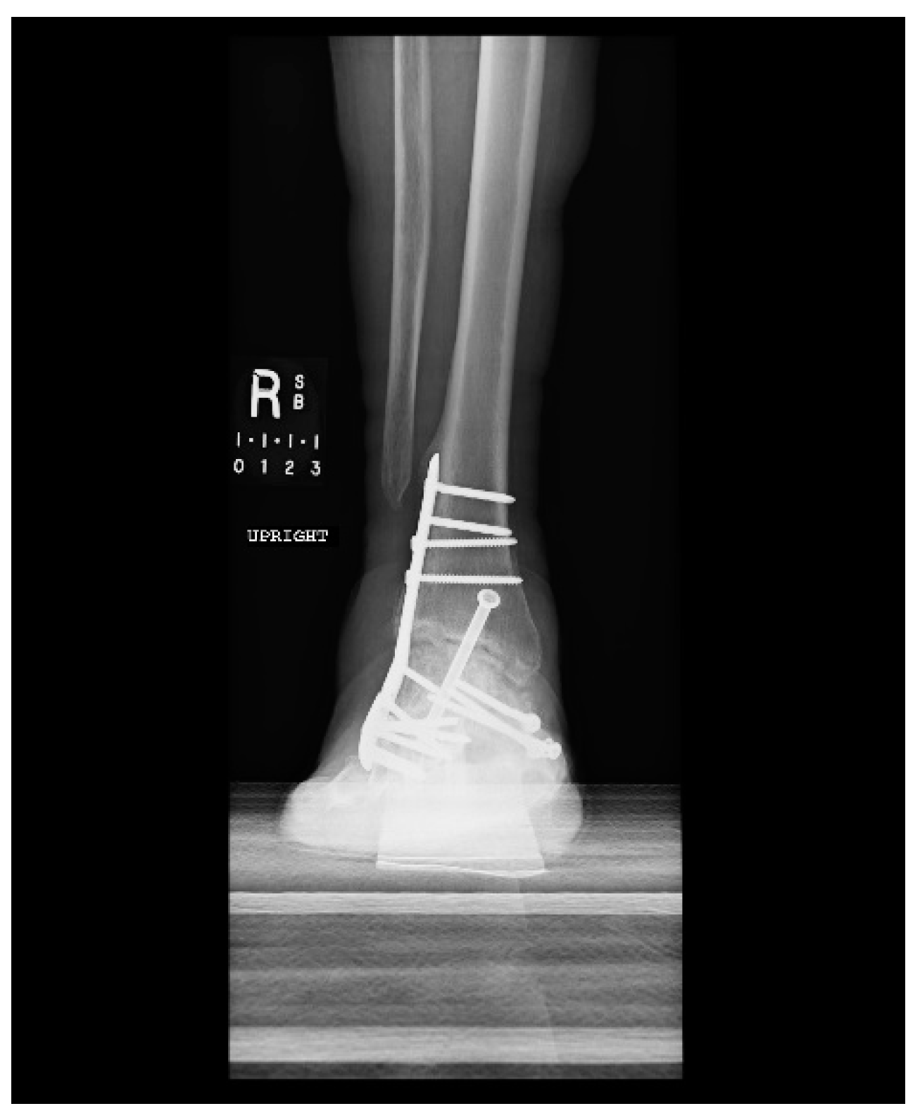
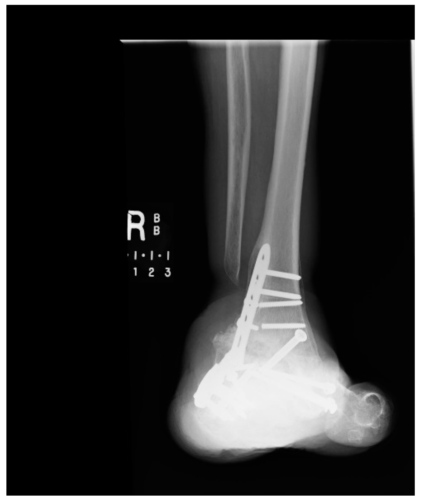
1.1.4. Post-Operative Imaging

X-rays from the 18-month post-op visit showed evidence of breakage of a distal 3.5 mm talonavicular screw (Figure A2). The fracture line was located in the thread near the screw head. At two years post-op, the screw breakage was more displaced and there was an additional fracture in the most proximal 3.5 mm cortical screw in the tibia (Figure A3). The fracture line of this screw was again in the thread near the screw head. At three years post-op, a new fracture of the most proximal 3.5 mm locking screw in the talus was present (Figure A4). There was also evidence of a newly forming valgus deformity. At five years post-op, an additional 3.5 mm cortical screw in the tibia, a second 3.5 mm talonavicular screw, the 6.5 mm cannulated screw, and the 3.5 mm LCP plate all exhibited fracture on imaging (Figure A5). At six years post-op, an additional 3.5 mm cortical screw in the tibia broke and the fractured plate became more widely displaced (Figure A6). The valgus deformity seen earlier had now progressed to nearly 30 degrees.

2. Materials and Methods

The PHILOS plate was made of Stainless Steel 316L, originally manufactured by Synthes, now Depuy Synthes Joint Reconstruction (Warsaw, IN, USA). The plate is anatomically shaped to the complex contours of the proximal humerus. The construct contains both locking and combination of locking and compression holes using different types of screws [24,25]. There are 10 locking holes in the distal end of the PHILOS permitting multiple points of fixation for support. The PHILOS has 5 combination holes, one elongated hole to aid in-plate positioning with a 3.5 mm locking screws hole in the threaded portion in the proximal shaft. There are also 3.5 and 4.0 mm cortical screw holes and 4.0 mm cancellous bone screws in the compression portion. All 18 pieces of the implant submitted for investigation are shown in Figure 1. Among the submitted pieces, only 4 screws were intact. The LCP, which was fractured into three pieces, was measured to be 114 mm in length and had a thickness of 3.5 mm.
In order to assess the mechanical and manufacturing integrity of the failed device, we preformed Rockwell hardness B-scale test and X-ray energy dispersive spectroscopy (EDS) using a Quanta 600 scanning electron microscope (SEM, Thermo Fisher Scientific, Hillsboro, OR, USA) with a 15 kV voltage and a spot size of 5. We compared the results from our testing to ASTM (American Society for Testing and Materials) standards reported for stainless steel 316L [26]. The Rockwell hardness test was performed in three different locations of the fractured plate with each test location increasing in distance away from the fracture surface. The EDS was performed using a 10 mm square detector and genesis software package. EDS was performed on both the fracture plate. EDS samples were taken both at the plate surface and plate interior to ensure homogeneity throughout both pieces.
One of the plate fragments was cleaned in ethanol followed by water sonication for 10 min to study the fracture surface. Fractography was performed using the SEM with a voltage of 15 kV and a spot size of 3. Electron backscatter diffraction (EBSD) was performed on an FEIXL-30 using an EDAX EBSD detector to determine the grain size and orientation.

3. Results and Discussion

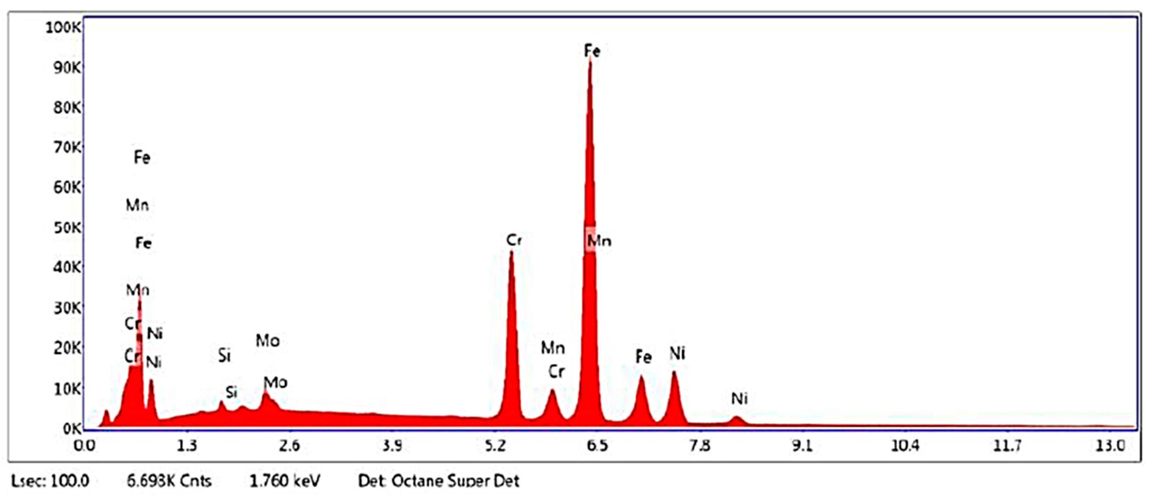
3.1. Chemical Composition Characterization

The results of the X-ray EDS for the fracture plate is shown in Table 1 and compared with reported ASTM standard for SS 316L stainless steel (F138-03). An additional requirement set forth by the ASTM standard is shown in Equation (1), which yielded 24.77 for the plate [26]. One factor to keep in mind when comparing EDS results to the ASTM standard is that EDS is known to be a semi-quantitative technique. In addition, adventitious carbon may have accumulated on the surface preventing C from being quantified. There is also an overlap between the X-ray peaks of Mo and S, precluding deconvolution of their concentrations. The EDS system used in this case was not sensitive enough to detect the trace amounts of P, S, and N expected according to the standard. The EDS spectrum is shown in Figure 2.
%   Cr + 3.3   × % Mo   26.0
The plate conformed to ASTM standards according to the tolerated ranges of element composition but failed equation 1 in this instance shown in Table 1. However, in another instance, the results of the composition analysis gave a result of 28.7 for Equation (1), thus passing the requirements.

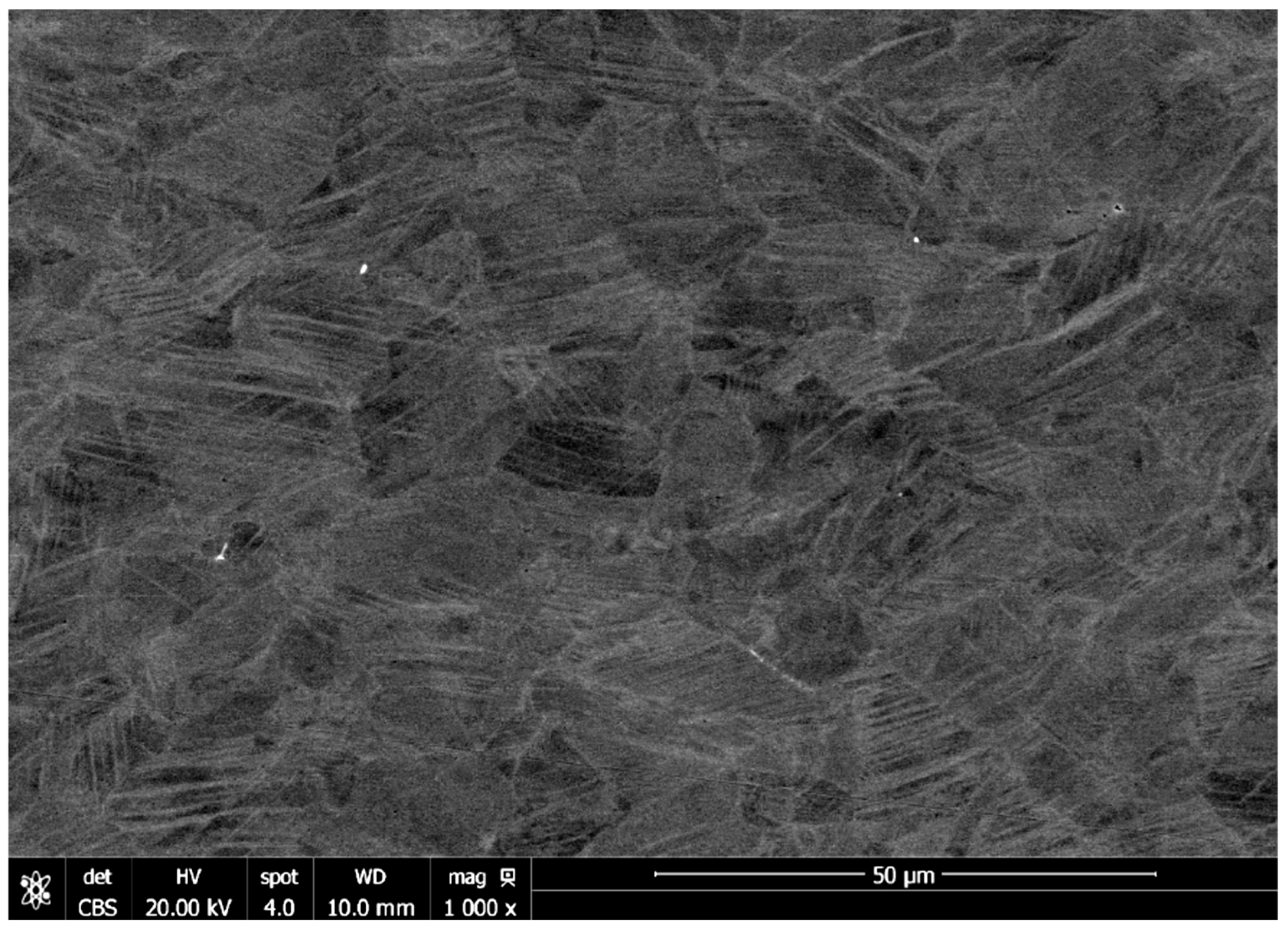
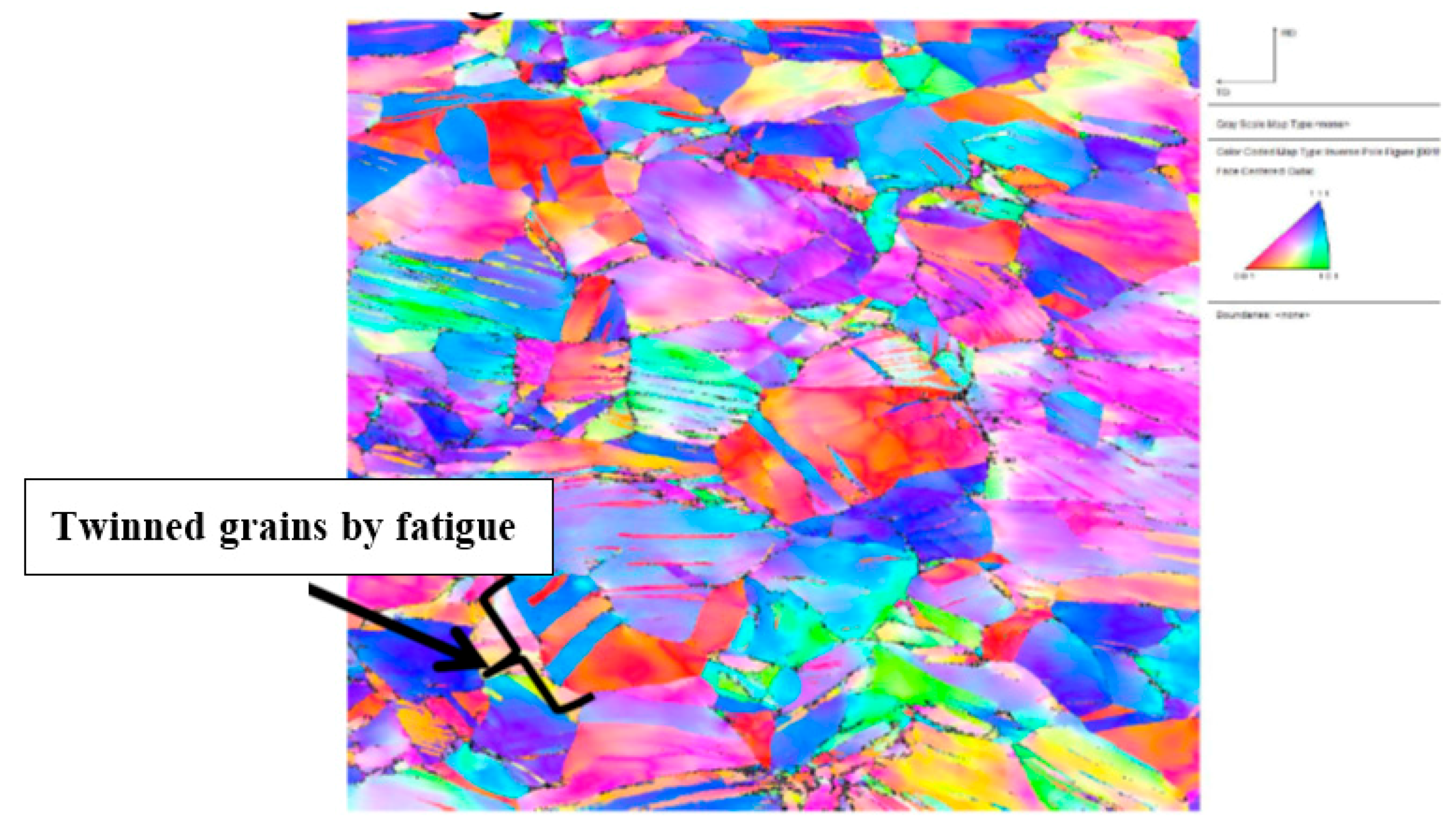
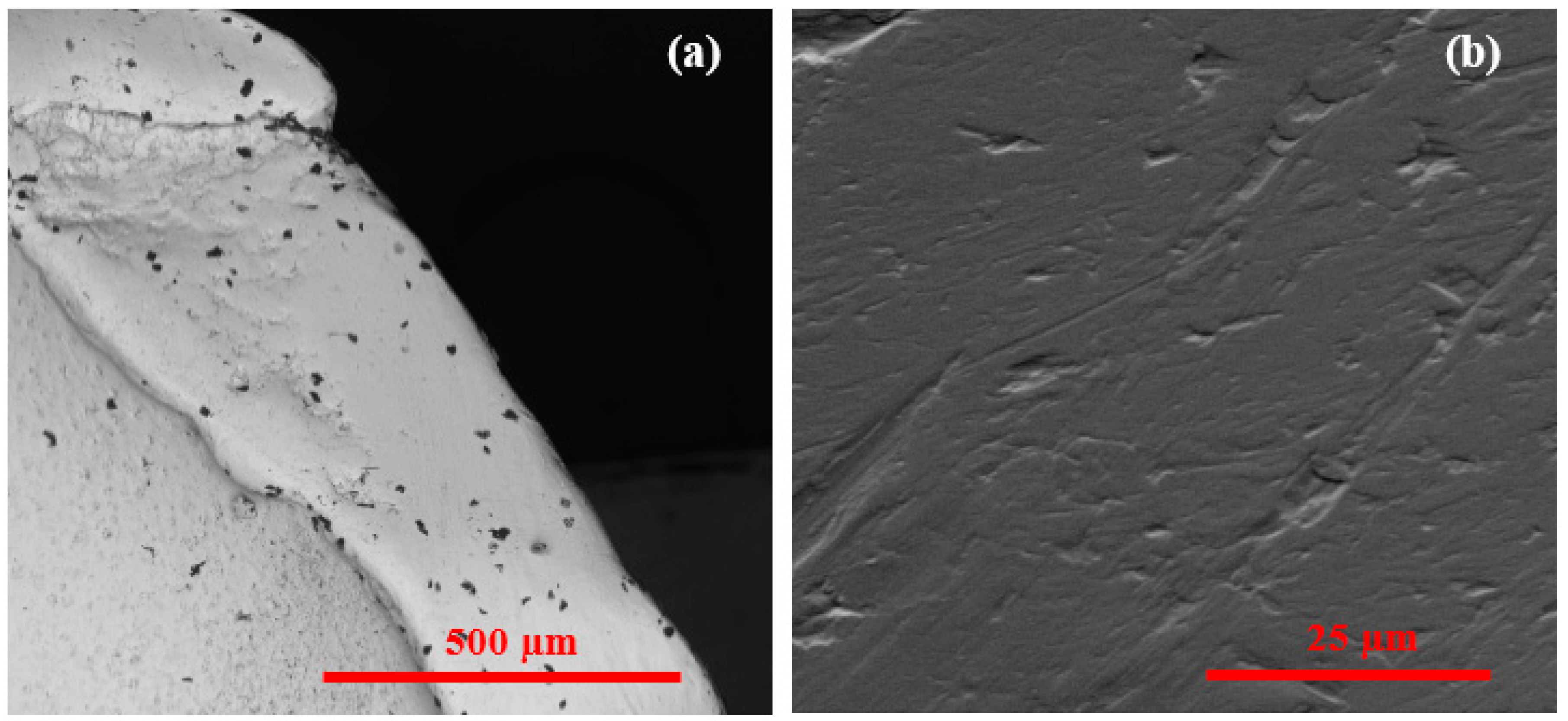
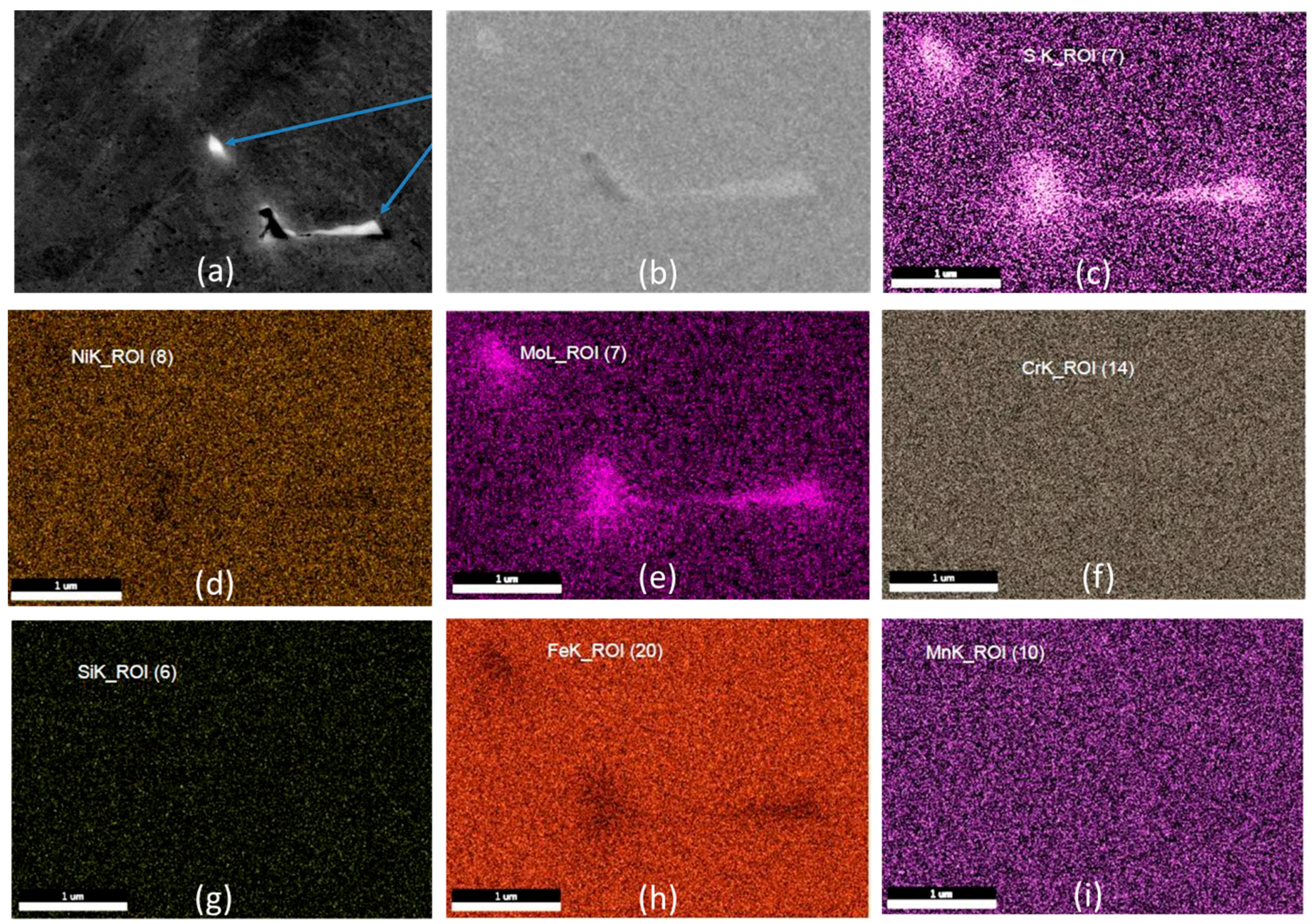
3.2. Microstructural Characterization

EBSD and backscatter imaging methods were used to characterize the structure of the material. The microstructure is shown in Figure 3. The range in the average grain size of the plate was four to six micrometers shown in Figure 4.
An attempt was made to identify and characterize the inclusions. Two regions of interest identified in Figure 1 as area 2 and 3, were investigated for inclusions and presented in Figure 5a,b. The composition of one inclusion was mapped in Figure 6 using EDS. The maps in Figure 6 show that inclusions are likely Mo rich (though this could be S), these inclusions may be fine, localized chi and sigma intermetallic phases which may have started the crack. There is a need to characterize inclusions in surgical grade SS 316L as a dedicated basic research focus since this paper deals with failure analysis and the importance that the inclusions have on failure initiation.

3.3. Material Property Analysis

The results of the Rockwell hardness B-scale test on the fractured plate are shown in Table 2. The ASTM standard upper limit for SS 316L is 95 HRB, and a 95% confidence interval was calculated for each trial. The hardness was then converted to Vickers hardness and tensile strength, and a 95% confidence interval was also calculated and used to compare against the ASTM standard for SS316L [26]. Hardness of the plate varied across the plate. It is evident that as the fatigue related deformation accrued, the material hardened across or near the fracture plane. It is likely that the material may have been supplied at higher strength conditions via cold working and may also have had reduced elongation.

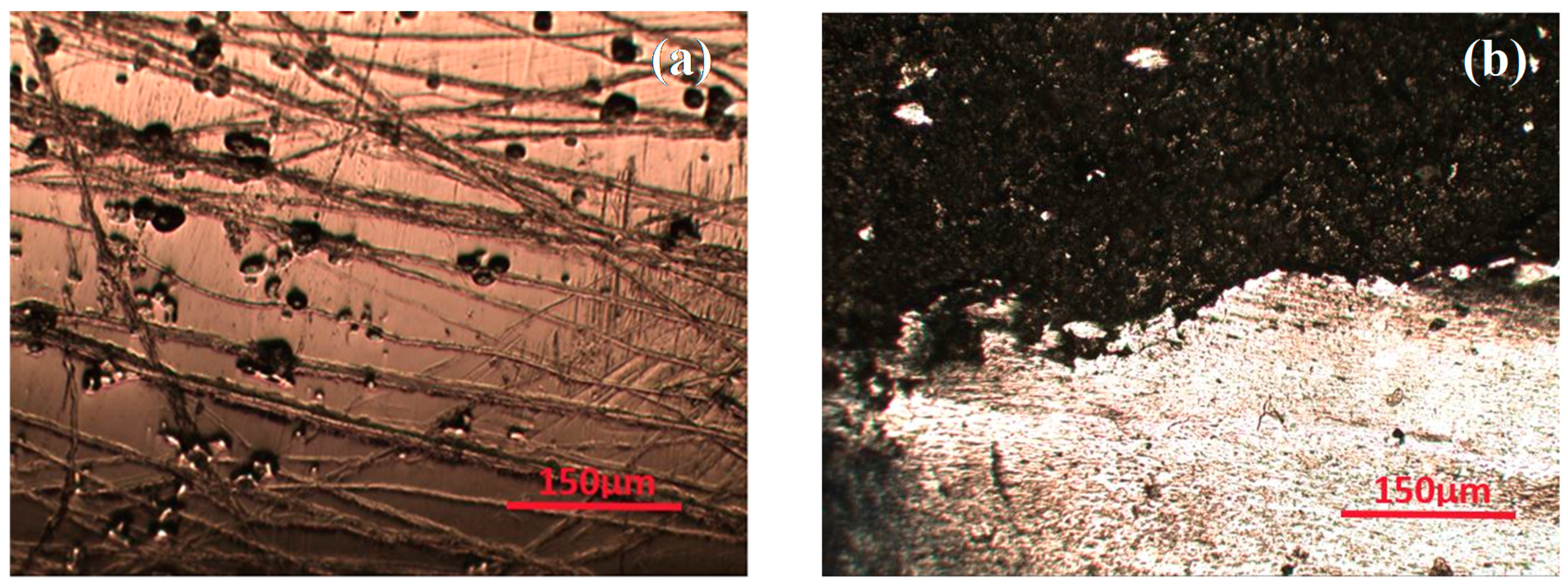
3.4. Optical Microscopic Analysis
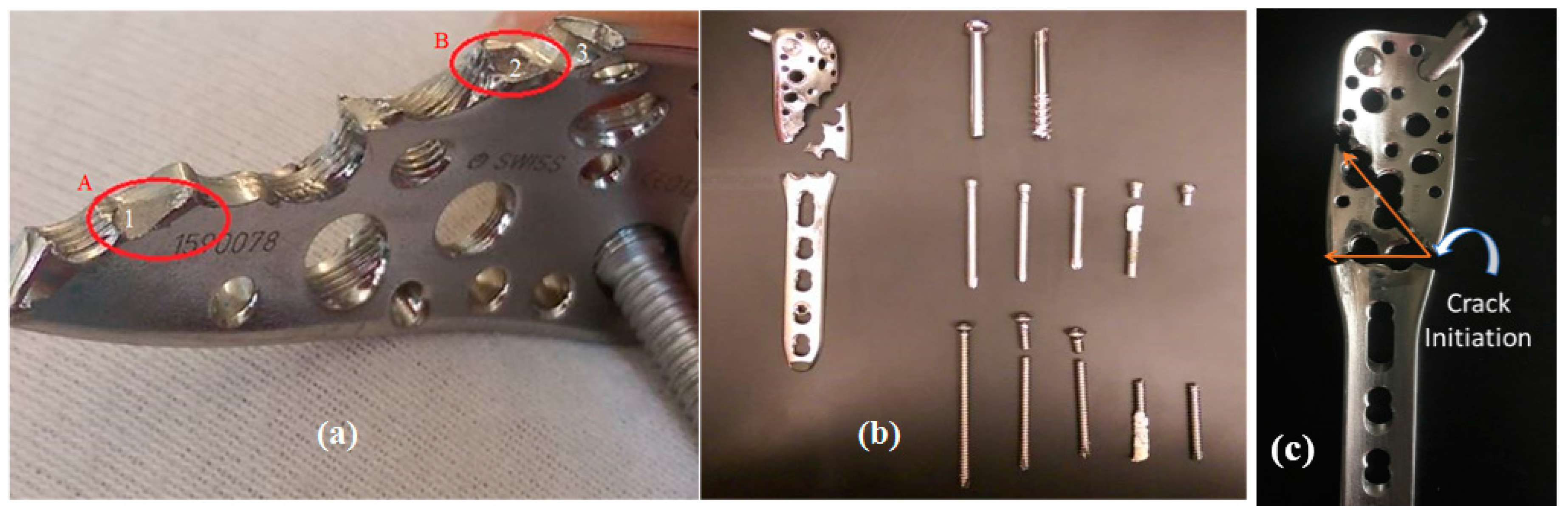
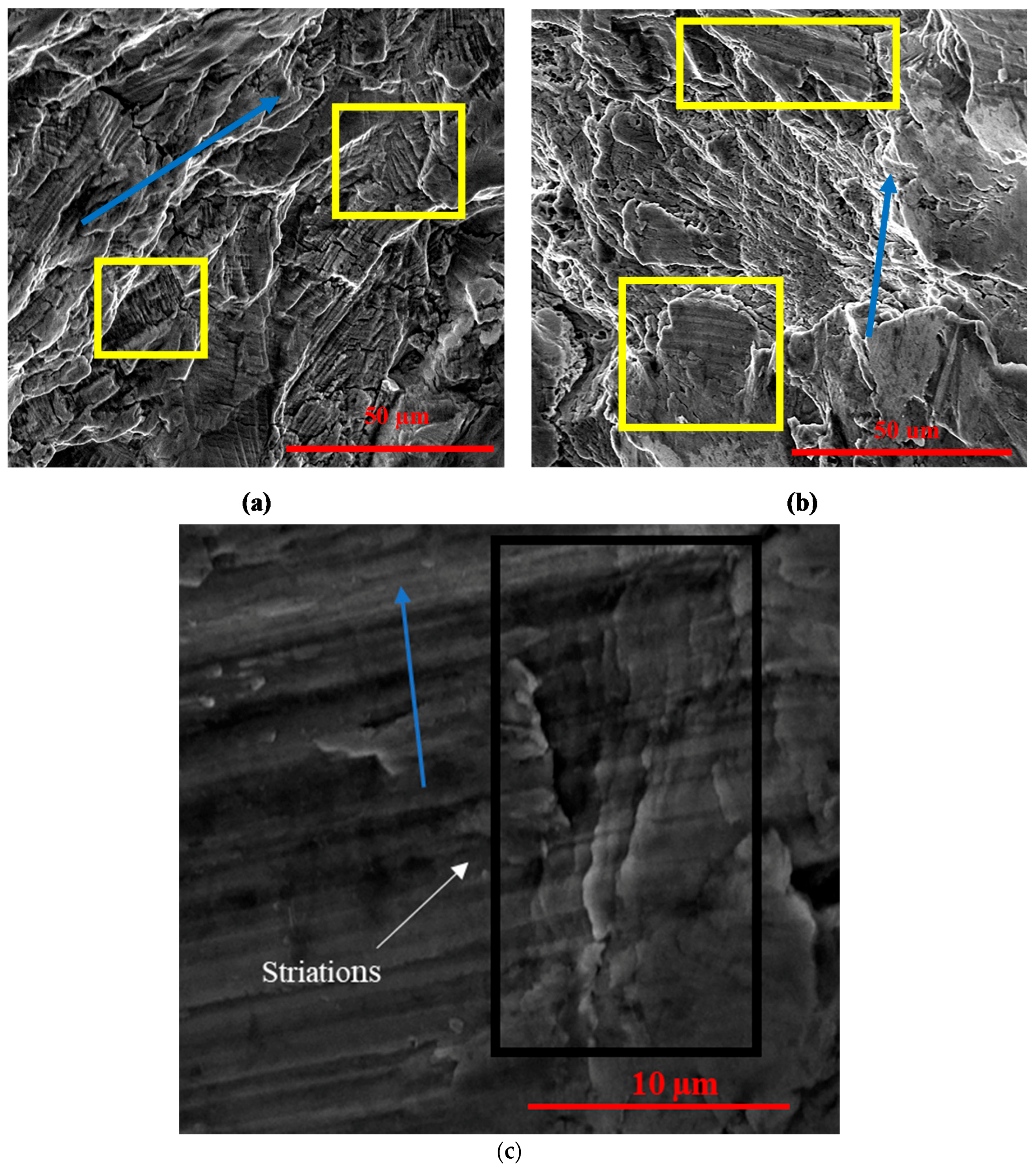
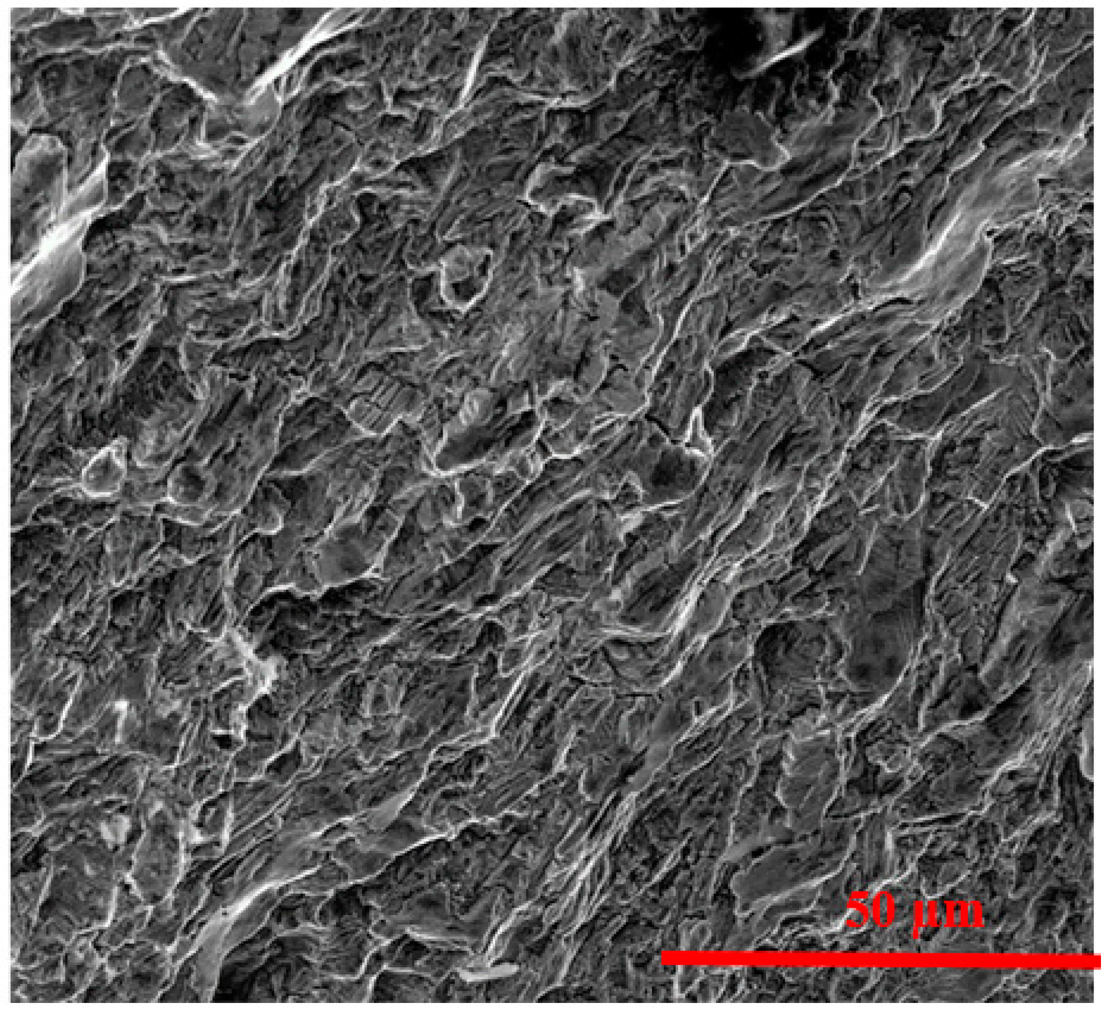
Visual observation indicated a large number of scratches on the surface of the plate. Two broken screw heads (with StarDrive recess) remained in the plate, while one partially intact locking screw was not removed from the distal end. Figure 1 shows that the crack initiated from under one of the locking screw holes near the middle of the plate. This fracture initiation has progressed in two different directions, one diagonally 45° in the directions of maximum shear and one perpendicularly (Figure 1), which caused the plate to fail into three pieces. The observed features are summarized in Table 3. Since the plate and screw construct was removed after it had failed, we do not know whether the material dissolution or contact between two mating surfaces during removal removed the pitting and or other localized damage sites prior to crack formation.

3.5. Fractography

The markings shown in Figure 7a are changes in surface elevation eluding to pitting in area of interest 3. Figure 5 shows EBSD image and distribution of different phases present in the material that may be described as non-metallic/inclusions. Non-metallic inclusions are known to be areas of stress concentration and increase the likelihood of pitting corrosion and secondary crack initiation. Sudhakar et al. and Kanchanomi et al. found that non-metallic inclusions initiated the eventual failure of devices in their studies [13,18]. This evidence of pitting and foreign body inclusions, seen in Figure 5 and Figure 6, respectively, supports secondary crack initiation due to corrosion-fatigue at these sites. Figure 8a–c show fatigue striations in the areas of interest 1, 2, and 3, respectively. Striations are evident within all three images. Figure 8a also shows some evidence of cleavage and facets. The striation spacing in each image was measured and displayed in Table 4. The arrows indicate the direction of crack propagation based on increase in striation spacing.
From these methods it is quite clear that striation spacing increased as the crack advanced through the three regions, 3 to 1, respectively. The origin for crack appears to be from area 3 (distal end of plate, latterly); however, as it advanced, the linking occurred through the screw holes in a 45° angle which may have coincided with dorsiflexion angle or slight movement by gait. Upon failure, the plate was not able to load bear along this angle, the load transferred perpendicularly causing cracking and linking through the screw holes in that direction as well.
The SEM imaging performed on the failed implant provides a strong argument for initial corrosion-fatigue fracture followed by brittle fracture for the mechanism of failure. Table A1 shows that Thapa et al., Karmacharya et al., Majid et al. and Azevedo et al. identified corrosion as an important factor in the failure of devices [11,12,13,19]. Fatigue fracture has been conservatively estimated to account for 50% of all brittle fractures in manufactured products, making fatigue fracture the most prevalent initiator of brittle fracture [27]. Striations due to secondary crack propagation were evident at multiple locations on the locking compression plate (Figure 8a–c). Thapa et al. came to the conclusion that a 10 hole locking compression plate led to failure after 2035 cycles with a striation spacing of 0.3–1.72 µm [14]. Goswami et al. showed striation spacing within a range of 10–15 µm for the fracture of an IM nail that led to an estimate of less than 100 cycles before fracture [22]. Based on the findings of previous research, it may be estimated that the plate may have accumulated a quarter of a million cycles by a stable crack propagation mechanism; however, as it jumped through the screw hole(s), the striation spacing increased. At location 1, the striation spacing was wide enough that failure may have occurred in the tertiary phase of crack propagation. However, the kinetics of how an inclusion transitioned to pitting and pit to crack is not known. These findings support evidence of secondary crack initiation, within the areas of non-metallic inclusions, as shown in Figure 9. The fatigue failure mechanism for SS 316L was in terms of excessive twinning as shown in Figure 10. However, twinning may also be a standard microstructure of SS316L and the available samples were made from the failed device; we cannot conclude whether or not the twinning were original microstructure or as a result of in vivo use.
The quasi-cleavage and facets seen in Figure 9 are highly characteristic of brittle fracture—an end consequence of corrosion-fatigue crack propagation. Imaging of the distal end of the failed piece on the optical microscope (Figure 7b) showed evidence of progressive fatigue fracture that eventually led to brittle fracture, depicted by the abrupt change in surface pattern. It is this brittle fracture that ultimately led to the failure of the PHILOS.
Azevedo et al. investigated multiple devices (femoral compression plate, femoral nail plate, and oral maxillo-facial plate) and discussed the importance of material conforming to ISO (International Organization for Standardization) and/or ASTM standards for these devices. Most devices investigated [19] failed by a corrosion-assisted fracture that can be traced back to improper chemical composition. Other devices investigated revealed fabrication or assembly defects that contributed to their premature failure [23]. Sivakumar et al. and Marcomini et al also showed that lack of chemical conformity in the alloy had led to the implant failure [19,20]. The results from the chemical and mechanical property analysis show a potential lack of conformity to ASTM standard. However, it is also possible that the material procurement protocols may have followed other specifications as the device was then marketed by Synthes (Solothurn, Switzerland). The microstructure of the SS316L, Figure 4, shows, given the orientation of various grains via colors in the Figure, that the grains are randomly distributed indicating a weak texture. The pitting resistance of the material has not been investigated; however, is triggered by the presence of MnS inclusions, not documented for this material.

4. Conclusions

Images taken at six weeks post-op showed no evidence of device failure. The implant failed mechanically as well as clinically. Failure in the device construct caused lack of union. The first follow-up X-ray images showing evidence of device failure via screw fracture were taken at 18 months post-op. The average time for tibiotalocalcaneal arthrodesis fusion is about 19 weeks. Since imaging evidence supports device failure initiating between six weeks and 18 months, it cannot be said with certainty that the device maintained its integrity for the amount of time necessary for fusion. The revision surgery implemented a pediatric distal femoral osteotomy plate. There is no follow-up data on the revision. The following are a few reasons that may be considered for the overall failure of the PHILOS plate:
  • As we know that the plate was designed for the proximal humerus, it did not match all the requirements of pantalar arthrodesis. A slight mismatch would give rise to forces sufficient to cause overloading failure.
  • The curvature in the plate is one of the important factors to be considered, due to which unequal load distribution could have taken place.
  • Improper reduction may be due to the device. This improper reduction may have generated excessive loading on the LCP leading to a premature mechanical failure.
  • The qualitative data of composition, non-metallic inclusions, hardness, and tensile strength of the plate show that the material conformity per ASTM standard may be an additional issue controlling the integrity of the device.
  • SEM imaging supports a mechanism of corrosion-fatigue fracture from crack initiation sites in the distal areas of the plate due to the presence of inclusion bodies and pits. These crack initiation sites can then lead to crack propagation towards the proximal area (shown by the striations) and ultimately brittle fracture (supported by the cleavage sites and facets).

Acknowledgments

Gerard Simon, Air Force Research Laboratory, Dayton, Ohio provided access to the characterization facilities. Dinesh Gundapaneni assisted with sample preparation, microstructure and hardness testing of the material.

Author Contributions

Madhurima Vallentyne did the initial work as a part of her independent research, Jason Ina continued the further characterization work. Michael Boin reviewed the patient charts and provided clinical insights. Kathleen Shugart performed the SEM analysis and texture related research. Farah Hamandi performed mechanical tests, theoretical aspects of the paper and in the revisions. Richard Laughlin performed the revision surgery and removed the device components. Tarun Goswami, led this research study, recruited students, medical students and residents, verified the analytical methods and edited or written the body of the paper.

Conflicts of Interest

The authors declare no conflict of interest.

Appendix A

Table A1. Summary of orthopaedic device failure modes.
StudyDevice DetailsAlloyFailure ModeDetails of Failure
Kanchanomai et al. [10]14 hole, Locking compression plate (for femur)316L Stainless steelExcessive walking before adequate healing of fracture
-
Striation spacing: 1 μm at the middle of the fracture
-
Thickness of LCP: 5 mm
-
Estimated no. cycles from crack initiation to bottom: 5000 cycles
-
Estimated number of cycles for complete fracture: 42,000 (8 days of walking)
-
Sub-surface inclusion found at initiation of crack site
Thapa et al. [11]10 hole, Locking compression plateStainless steelCorrosion-fatigue
-
Striation spacing: at crack initiation—0.3 μm, at fracture surface—1.72 μm (crack length—1 mm).
-
Estimated no. of cycles after crack initiation: 2035 cycles
-
Corrosion (rusting) visible on surface
-
Carbon intermetallic-inclusion found
Karmacharya et al. [12]8 hole, Reconstructive locking plate316L Stainless steelCorrosion
-
Mechanically intact & no significant damage visible
Majid et al. [13]Lumbar plates (113 plates were studied)316L Stainless steelCorrosion
-
72.5% (majority) of plates showed corrosion.
-
Fe, Cr and Ni (preferential) metal ions were released into body due to corrosion
-
Corrosion occurred at screw-plate interface (fretting/crevice)
Varadharajan et al. [14]Hemi-toe implantCobalt chromium alloyFailed clinically
-
Mechanically intact & no significant damage visible
-
Anterior/middle surface exhibited more scratching/debris deposition—can be indicative of damage to HMWPE bearing
-
Coat spalling may indicate device loosening
Sudhakar et al. [15]Nail for Shinbones316L Stainless steelDuctile fracture and nonmetallic inclusions
-
Ductile fracture facilitated by micro-fracture due to non-metallic inclusion (125 um) is predominant mode of failure
Sivakumar et al. [16]6 hole, Tubular compression bone plate (for femur)316L Stainless steelImproper fixation
-
Pitting potential of implant is due to higher Chromium—2.3% and Nickel—4% contents.
-
Fracture was at 5th countersunk hole of plate
-
“Beach marks” at outer edge of crack indicate torsional force
-
Grain size and inclusion content did not meet ASTM requirement
-
Bone plate was placed anteriorly rather than laterally which does not allow for proper compression
-
Screw head and screw hole mismatch
Marcomini et al. [17]Femoral Locking compression plateStainless steel (not 316L due to higher content of Ni and P)Non-conformity of the material
-
Phosphorus content 0.26% over superior limit
-
SEM showed evidence of brittle fracture due to segregation of P in grain boundaries
-
Steel was cold worked which contributed to brittle fracture
Cahoon et al. [18]McLaughlin plate for hip (7 other implants discussed)Cast VitalliumFracture in the area where maximum stresses were expected
-
Period of time the implant served: 1 year
-
Fatigue strength decreased due to increase in porosity
Cahoon et al. [18]V-Moore plate and screws316L Stainless steelCrevice corrosion
-
Period of time the implant served: 1 year
-
Tissue reaction due to severe crevice corrosion
Cahoon et al. [18]Nail plate316L Stainless steelFracture due to bending (while trying to fit the patient)
-
Punching of screw holes too close and too near to the edge of the nail plate
-
To dissolve the precipitation of chromium carbide, it was heat treated at: 1040 °C for 1 h.
Azevedo et al. [19] 13 hole reconstruction plate for osteosynthesisPlate: CP Titanium Screws: Titanium-6Al-4V alloyCorrosion-fatigue
-
Intergranular cracking formation: 15 μm deep on notch surface
-
Reduction of area featured: 55% approximately.
-
Equiaxed α grains and Intergranular β platelets revealed
-
Corrosion observed on intergranular β-phase which was in contact with body fluid
De Medeiros et al. [20]Hemimandibles with assistive 4 hole plates5052-F AluminumFracture due to ductile overload
-
Number of plates fractured in the upper part of the hole to the right of the fracture line: 5
-
Surface: Dim and grayish showing intense plastic deformation
-
Plates failed due to ductile fracture mechanism alluding to proper manufacturing
Roffey et al. [21]Femoral stemM30NW High nitrogen Stainless steelFailure at a point of maximum stress due to bending and torsional loading
-
No. of fracture initiation points: 2
-
Large Beach marks indicate large number of cycles to failure
-
Visible ratchet marks indicative of fatigue failure
-
Scratching and scoring patterns support post-manufacturing damage
-
Fatigue fracture pattern confirms mechanical damage prior to fracture
-
Initial fracture occurred in region of lowest cross-sectional area
-
Mechanical damage to surface during implantation led to initiating fatigue crack
Goswami et al. [22]IM nailTitaniumAxial, bending, and torsion forces
-
Interference between screw, core-lock caps, and IM nail
-
Lack of purchase to bone
-
Pre-crack due to interference
-
Striation spacing = 10–15 µm
Azevedo et al. [23]Femoral compression plateStainless steelFretting-fatigue
-
Underside of screw-head and plate hole countersink showed marks of wear and corrosion that led to removal of passivation layer
-
Chemical composition did not meet ISO 5832-I standards which decreases corrosion resistance
-
Presence of fretting corrosion may suggest screw loosening
-
Fatigue striations (spacing = 0.6 µm) associated with secondary cracking
Azevedo et al. [26]Femoral nail-plateStainless steelFatigue fracture
-
Multiple nucleation sites present at high-stress concentration points
-
Chemical composition failed to meet ISO 5832-I standards
Azevedo et al. [23]Titanium oral maxilla-facial plateCP TitaniumCorrosion-fatigue
-
Evidence of brittle fracture shown by no gross plastic deformation near fracture surface
-
Presence of fissure striations, complex furrow structures, secondary intergranular cracking
-
Intergranular cracking near surface of origin indicative of corrosion—fatigue mechanism
-
ISO 5832-2 standards were met for chemical composition of CP titanium

Appendix B

Radiological Features Showing Placement of Devices and Gradual Failures
Figure A1. Initial X-Ray images showing lateral subtalar dislocation with varus tibiotalar joint alignment.
Metals 08 00180 g0a1
Figure A2. 18 months post-op imaging with evidence of breakage of a distal 3.5 mm talonavicular screw.
Metals 08 00180 g0a2
Figure A3. 2 years post-op imaging with screw fracture more displaced and an additional fracture in the proximal 3.5 mm cortical screw in the tibia.
Metals 08 00180 g0a3
Figure A4. 3 years post-op showing new fracture of the most proximal 3.5 mm locking screw in the talus.
Metals 08 00180 g0a4
Figure A5. 5 years post-op with additional fractures in a 3.5 mm cortical screw in the tibia, a second 3.5 mm talonavicular screw, the 6.5 mm cannulated screw, and the 3.5 mm LCP plate.
Metals 08 00180 g0a5
Figure A6. 6 years post-op with an additional fracture in a 3.5 cortical screw in the tibia and the fractured plate became more widely displaced. The valgus deformity seen earlier had now progressed to nearly 30 degrees.
Metals 08 00180 g0a6

References

  1. Quill, G.E., Jr. Tibiotalocalcaneal arthrodesis. Tech. Orthop. 1996, 11, 269–273. [Google Scholar] [CrossRef]
  2. Coughlin, M.J.; Nery, C.; Baumfeld, D.; Jastifer, J. Tibiotalocalcaneal Arthrodesis with lateral compression Plate. Rev. Bras. Ortop. 2012, 47, 467–473. [Google Scholar] [CrossRef] [PubMed] [Green Version]
  3. Ortho Info. Internal Fixation for Fractures. American Academy of Orthopaedic Surgeons. Available online: https://orthoinfo.aaos.org/en/treatment/internal-fixation-for-fractures/ (accessed on 13 August 2015).
  4. Sommer, C.; Gautier, E.; Müller, M.; Helfet, D.L.; Wagner, M. First clinical results of the Locking Compression Plate (LCP). Injury 2003, 34, 43–54. [Google Scholar] [CrossRef]
  5. Kubiak, E.N.; Fulkerson, E.; Strauss, E.; Egol, K.A. The evolution of locked plates. J. Bone Jt. Surg. 2006, 88 (Suppl. 4), 189–200. [Google Scholar]
  6. Ahmad, M.; Nanda, R.; Bajwa, A.S.; Candal-Couto, J.; Green, S.; Hui, A.C. Biomechanical testing of the locking compression plate: When does the distance between bone and implant significantly reduce construct stability? Injury 2007, 38, 358–364. [Google Scholar] [CrossRef] [PubMed]
  7. Desai, K. A Biomechanical Comparison of Locking Compression Plate Constructs with Plugs/Screws in Osteoporotic Bone Model. Master’s Thesis, Wright State University, Fairborn, OH, USA, 2010. [Google Scholar]
  8. Ahmad, J.; Pour, A.E.; Raikin, S.M. The modified use of a proximal humeral locking plate for tibiotalocalcaneal arthrodesis. Foot Ankle Int. 2007, 28, 977–983. [Google Scholar] [CrossRef] [PubMed]
  9. Twaij, H.; Damany, D. PHILOS humerus plate for a distal tibial fracture. J. Surg. Case Rep. 2013, 2013, rjs036. [Google Scholar] [CrossRef] [PubMed]
  10. Kanchanomai, C.; Phiphobmongkol, V.; Muanjan, P. Fatigue failure of an orthopedic implant—A locking compression plate. Eng. Fail. Anal. 2008, 15, 521–530. [Google Scholar] [CrossRef]
  11. Thapa, N.; Prayson, M.; Goswami, T. A failure study of a locking compression plate implant. Case Stud. Eng. Fail. Anal. 2015, 3, 68–72. [Google Scholar] [CrossRef]
  12. Karmacharya, S.; Goswami, T. Analysis of a clinically failed, mechanically intact, reconstructive compression plate. Case Studies in Engineering Failure Analysis. Trauma Cases Rev. 2015. [CrossRef]
  13. Majid, K.; Baker, K.C.; Baker, E.A.; Koueiter, D.M.; Herkowitz, H.N. High Rate of Corrosion of 316L Stainless Steel Plates Used in Posterior Thoracolumbar Fixation: A Retrieval Study. In Proceedings of the 55th Annual Meeting of the Orthopaedic Research Society, Las Vegas, NV, USA, 22–25 February 2011. [Google Scholar]
  14. Varadharajan, S.; Laughlin, R.; Goswami, T. Analysis of clinically failed, mechanically intact, hemi-toe implant. Case Studies in Engineering Failure Analysis. J. Biomed. Eng. Biosci. 2016, 3, 22–25. [Google Scholar]
  15. Sudhakar, K.V. Metallurgical investigation of a failure in 316L stainless steel orthopaedic implant. Eng. Fail. Anal. 2005, 12, 249–256. [Google Scholar] [CrossRef]
  16. Sivakumar, M.; Kamachi Mudali, U.; Rajeswari, S. Investigation of failures in stainless steel orthopaedic implant devices: Fatigue failure due to improper fixation of a compression bone plate. J. Mater. Sci. Lett. 1994, 13, 142–145. [Google Scholar] [CrossRef]
  17. Marcomini, J.B.; Baptista, C.A.R.P.; Pascon, J.P.; Teixeira, R.L.; Reis, F.P. Investigation of a fatigue failure in a stainless steel femoral plate. J. Mech. Behav. Biomed. Mater. 2014, 38, 52–58. [Google Scholar] [CrossRef] [PubMed]
  18. Cahoon, J.R.; Paxton, H.W. Metallurgical analyses of failed orthopedic implants. J. Biomed. Mater. Res. 1968, 2, 1–22. [Google Scholar] [CrossRef] [PubMed]
  19. Azevedo, C.R.F. Failure analysis of a commercially pure titanium plate for osteosynthesis. Eng. Fail. Anal. 2003, 10, 153–164. [Google Scholar] [CrossRef]
  20. De Medeiros, R.C.; de Moura, A.L.; Rodrigues, D.C.; Mendes, M.B.M.; Sawazaki, R.; Moreira, R.W.F. Fractographic analysis of 2.0-mm plates with a screw locking system in simulated fractures of the mandibular body. J. Oral Maxillofac. Surg. 2014, 72, 1130–1137. [Google Scholar] [CrossRef] [PubMed]
  21. Roffey, P. Case study: Failure of a high nitrogen stainless steel femoral stem. Eng. Fail. Anal. 2012, 20, 173–182. [Google Scholar] [CrossRef]
  22. Gundapaneni, D.; Slocum, M.; Paul, P.; Christof, S.; Goswami, T. Failure Investigation of a Tibiotalocalcaneal Arthrodesis System. Eng. Fail. Anal. 2016, 59, 588–604. [Google Scholar]
  23. SYNTHES. 3.5 mm LCP Proximal Humerus Plate—Stainless Steel and Titanium Technique Guide. 2002. Available online: http://synthes.vo.llnwd.net/o16/LLNWMB8/US%20Mobile/Synthes%20North%20America/Product%20Support%20Materials/Technique%20Guides/DSUSTRM10161133_ProxHumPl_STG_150dpi.pdf (accessed on 9 June 2015).
  24. SYNTHES. Small Fragment Locking Compression Plate (LCP) System. Stainless Steel and Titanium-Technique Guide. 2002. Available online: http://synthes.vo.llnwd.net/o16/Mobile/Synthes%20North%20America/Product%20Support%20Materials/Technique%20Guides/SUSA/SUTGSmFrgLCPJ3908I.pdf (accessed on 9 June 2015).
  25. Annual Book of ASTM Standards (Vol. 13.01), American Society for Testing and Materials: West Conshohocken, PA, USA, 2005.
  26. Azevedo, C.; Hippert, E. Failure analysis of surgical implants in Brazil. Eng. Fail. Anal. 2002, 9, 621–633. [Google Scholar] [CrossRef]
  27. Powell, G.W.; Mahmoud, S.E. ASM Handbook, 9th ed.; American Society for Metals: Metals Park, OH, USA, 1986; Volume 11. [Google Scholar]
Figure 1. Submitted proximal humerus internal locking system (PHILOS) device for analysis; (a) plate through the thickness shows regions of interests marked by A and B and 1–3 investigated in this paper (b) the failed samples and (c) crack initiation and propagation of the plate.
Metals 08 00180 g001
Figure 2. Energy dispersive X-ray analysis shows qualitatively the peaks of different element weight percent present in the PHILOS plate.
Metals 08 00180 g002
Figure 3. Microstructure of PHILOS plate at 1000 × .
Metals 08 00180 g003
Figure 4. Electron backscatter diffraction (EBSD) grain map of the PHILOS plate.
Metals 08 00180 g004
Figure 5. Backscattered electron images of likely inclusions (a) SEM EBSD image of area 2 (b) Topographical SEM image of area 3.
Metals 08 00180 g005
Figure 6. Characterization of inclusions using EDS. (a) The inclusions, (b) Gray scale of inclusions. Overlapping spectra of S and Mo visible in (c) Sulfur and/or (d) Nickel, (e) Molybdenum in the microstructure of the PHILOS plate. While the rest (f) Chromium, (g) Silicon, (h) Iron and (i) Manganese are not visible.
Metals 08 00180 g006
Figure 7. Light microscopy images showing (a) scratches and uniform pitting, and (b) debris and discoloration.
Metals 08 00180 g007
Figure 8. SEM images of (a) area 1, (b) area 2, and (c) area 3 showing striations perpendicular to crack propagation. The yellow boxes show striations and blue arrows denote the direction of crack propagation.
Metals 08 00180 g008
Figure 9. SEM image taken at area of interest 1. This image contains examples of quasi-cleavages and facets.
Metals 08 00180 g009
Figure 10. Inverse pole figure showing crystallographic characterization of the plate microstructure showing twinning that may have occurred due to in vivo use by fatigue or a material feature.
Metals 08 00180 g010
Table 1. X-Ray energy dispersive spectroscopy (EDS) measured composition for plate (wt %).
CompositionASTM Standard (Max)Plate (Average)Tolerance Limits
C0.03-0.005
Mn2.01.810.04
Si0.750.590.05
P0.025-0.005
S0.01-0.005
Cr17–1917.610.05
Mo2.25–3.02.170.15
Ni13–1513.840.2
N0.10-0.01
FeBalance63.99-
Table 2. Rockwell hardness B-scale test, Vickers hardness, and tensile strength results.
The TestAverageASTM StandardProximalMiddleDistal
Rockwell hardnessAverage95101.8107.7107.8
95% confidence interval-101.1–102.5106.1–109.3106.6–109.5
Vickers hardnessAverage213266.5330334.5
95% confidence interval-260–273310–350316–353
Tensile strength (psi)Average (MPa)86884810571057
95% confidence interval-837–8591004–11101004–1110
Table 3. Various damage features on different parts of implant.
LocationDamage Feature(s)
Distal area (Figure 1B)Scratches and pits
Close to fracture plane (Figure 1A)Scratches, pits, corrosion, cracking
Area (A), (Figure 1)Debris, discoloration
Table 4. Striation spacing range.
Reference ImageStriation Spacing (µm)
Figure 8c (area 3)0.44–0.99
Figure 8b (area 2)0.80–1.42
Figure 8a (area 1)1.91–4.95

