An Energetic Approach to Predict the Effect of Shot Peening-Based Surface Treatments

Politecnico di Milano, Department of Mechanical Engineering, 21056 Milan, Italy
*
Author to whom correspondence should be addressed.
Metals 2018, 8(3), 190; https://doi.org/10.3390/met8030190
Submission received: 13 February 2018
/
Revised: 12 March 2018
/
Accepted: 13 March 2018
/
Published: 17 March 2018
(This article belongs to the Special Issue Kinetic Surface Treatments)
Abstract
:Almen intensity and surface coverage are well-known to be the defining parameters of shot peening-based surface treatments. These parameters are directly affected by material properties, the extension of the contact zone, the geometry of the impact pair, as well as the impact rate and velocity. Such intricate relationships have resulted in often dissimilar predictions of shot peening effects even while using an identical combination of Almen intensity and surface coverage. With the fast pace introduction of new generation impact-based surface treatments, there is a need to find a more widespread parameter that would facilitate the direct comparison of all different treatments and relate the main process parameters to the resultant mechanical characteristics. Herein, we propose to use an energy-based parameter to describe the peening process in a more widespread approach, which collectively incorporates the effects of the Almen intensity and surface coverage, as well as the diameter, material, and velocity of the impact media. A set of finite element analyses was developed to demonstrate the correlation of the peening process effects with this energetic approach. Comparisons with the experimental data served as proof of concept, confirming that the proposed method could provide a quite good estimation of the effect of peening parameters on the treated material.
1. Introduction
Shot peening is a surface treatment process mainly known for its favorable effects in enhancing the fatigue strength of mechanical components. It has been widely used in machinery, aerospace, the automotive industry, and railway systems for decades. This process consists of impacting the material surface with high velocity peening media (mainly steel shots or ceramic beads) to generate inhomogeneous plastic deformation and consequently induce compressive residual stresses on the surface layer of the treated material. With the advancement of technology and development of high tech equipment, the concept of shot peening, which is based on inducing plastic deformation with repetitive high frequency impacts, has been recently extended to a vast range of cutting-edge impact-based surface treatments. The surface treatments of the new generation were developed to amplify the desirable effects of the conventional shot peening for a wider variety of applications ranging from classic industrial applications to biomedical ones [1,2,3,4,5]. These processes can be listed as ultrasonic shot peening (USSP) [6,7], high energy shot peening (HESP) [8], surface mechanical attrition treatment (SMAT) [9,10,11,12], surface nanocrystallization and hardening [13], severe shot peening (SSP) [4,14,15], sandblasting and annealing [16], ultrasonic impact treatment (UIT) [17], and ultrasonic impact peening [18], to name just the most noted ones. It is also to be underlined that some of these methods are basically using the same setup and mechanism and have been named differently due to the lack of consistency in the literature. Nevertheless, what all these methods have in common is the application of severe plastic deformation through high energy impacts to induce grain refinement, hardening, and compressive residual stresses through recurrent impacts with shots, balls, or pins using various loading schemes. Whatever the apparatus and loading arrangement, the obtained results are mainly influenced by a few parameters that all the aforementioned peening treatments share. The critical parameters are the indentation size produced by a single impact, which is in turn affected by impact velocity and impacting media’s material and geometry, as well as the total exposure time. Exposure time is defined as the duration of the peening treatment when the target material is being impacted by the peening media. These factors are practically set through two pragmatic parameters used in conventional shot peening to control the consistency and facilitate the replication of the process; i.e., Almen intensity and surface coverage. Almen intensity is the industrial measure of the kinematic energy of the shot stream and is calculated by measuring the curvature of standard Almen strips exposed to a shot stream at the saturation point. The saturation point refers to the first point on the arc height versus exposure time curve, where doubling the exposure time does not change the arc height by more than 10% [19]. Although recognized as the universal parameter of shot peening, the estimation of Almen intensity is not straightforward and necessitates the use of an apposite Almen strip and Almen gauge. Surface coverage, on the other hand, is the ratio of the plastically deformed area to the whole treated surface area. Considering the exponential behavior of surface coverage over time, coverages higher than 98% (the highest surface coverage that can be measured visually, also known as full coverage) are estimated by multiplying factors to the time required to reach full coverage [20].
For a long time, many researchers have tried to provide empirical graphs, formulations, and numerical simulations to relate these main process parameters with the mechanical behavior of the treated material. There have been a few successful efforts regarding the distribution of residual stresses [21,22,23], work-hardening [24], and the induced surface roughness [25]. However, most available approaches are either limited to specific sets of process parameters and limited materials, or they are applicable to a range of process parameters and thus cannot be straightforwardly generalized. Besides, Almen intensity and surface coverage themselves are associated with multiple process parameters. For example, surface coverage is directly affected by the interaction between the impact pair, their material properties, and the contact zone, which are in turn affected by the geometry of the shot and target material as well as the mass flow and peening velocity. Hence, there are reports of obtaining different distributions of residual stresses and extensions of plastically deformed areas, using the same combination of Almen intensity and surface coverage [26,27].
Herein, we propose that rather than using a combination of parameters such as Almen intensity, shot diameter, shot material, shot velocity, and surface coverage to provide an inclusive estimation of the effect of peening parameters on the functionality of the treated material, a single parameter that is directly related to the impact energy can be used for this purpose. A finite element model (FEM), previously developed by the authors of Reference [14] and updated to incorporate varying impact angles and to implement both single impact and multiple impacts, has been used to prove the concept of the idea. The suggested energetic approach entails the effect of all factors associated with the media stream including its size, material properties, and velocity into one single parameter, and has the potential to be generalized for any impact-based surface treatment. A set of experimental test data, from which we had access to all the process parameters and residual stress distributions, was simulated by FEM analysis to check the prediction of the energetic approach and assess its validity.
2. Description of the Finite Element Model
In this study, the kinetic energy of the shots upon impact is considered as the key parameter dictating the ensuing effect of the process on the treated material. Based on the properties of the contact pair, fractions of energy are consumed to result in plastic deformation, friction and surface damage production in the form of a potential fracture and possible heat production. Assuming that the friction-induced heat and fracture can be negligible, the main portion of the transferred energy is absorbed by the plastic deformation and indentation formation on the target surface. Here, we have developed a numerical model based on a FEM analysis of the SSP process previously presented by the authors of Reference [14]. The model is developed using the commercial software Abaqus/Explicit 6.12 (Simulia™, Dassault systemes®, Vélizy-Villacoublay, France) and consists in a rectangular block of (3 × 3 × 1.5 mm3) with a central impact area of (1 × 1 × 0.5 mm3), both meshed using C3D8R elements. The bottom part of the model was covered by infinite elements to provide stable results after impact. The Chaboche nonlinear combined isotropic/kinematic hardening model for AISI 304L stainless steel was used as the constitutive model of the target material [28]. Steel shot, on the other hand, was modeled as an elastic semi-sphere (doubling the density to reduce the number of elements while maintaining the kinetic energy) meshed using C3D4 tetrahedral elements. A mesh convergence analysis was performed following the approach adopted in Reference [29] considering both distributions of residual stresses and equivalent plastic strain (PEEQ) in the impact zone. Accordingly, elements of 1/20th and 1/10th the size of the average single indentation diameter were used to mesh the impact zone and the shot, respectively. The shot velocity was considered as a vector indicating the impact angle and its absolute velocity. The interaction between the shot and the impact area was defined as a general contact with a coulomb friction coefficient of μ = 0.2. The reader is directed to the original paper [14] for additional details on the FEM analysis.
3. Single Impact Model
The plastic indentation size is of primary importance in characterizing the impact-based surface treatments since it actually connects and controls the main two parameters of Almen intensity and surface coverage. Increases in the indent size correspond to higher Almen intensities and results in higher surface coverage, for a given number of impacts [30]; it will consequently affect the induction of residual stresses, surface work hardening, surface roughness and topographical morphology.
It is known that as the shot impacts the surface and rebounds, a portion of its initial kinetic energy (½ mv2) will cause a deformation in the target material. Since the indent size is directly modulated by the converted kinetic energy, this energy can be considered as a decisive parameter, which affects all the subsequent outcomes of the peening treatment. Considering the importance of the plastic indentation size, this initial single impact analysis is devoted to providing an accurate estimation of it. There are few simple empirical equations suggested for the estimation of the indentation size. Kirk [30,31] took the effects of shot diameter (d), its density (ρ), and velocity (v) as well as the target material properties into account to evaluate the indentation size. In this approach, target surface Brinell hardness (kgf/mm2) and the coefficient of restitution (e) were considered to assess the interaction of the shot and the target surface. This coefficient is to account for the retained energy as the shot bounces off the target surface and is defined as in Equation (1) in which h1 is the initial drop height of the shot and h2 is the height it bounces off upon impact on the flat surface. Kirk [30] suggested that e can be reasonably estimated to be 0.71 for the interaction of the steel shot with the steel surface. Equations (2) and (3) are proposed by Kirk to correspondingly predict the circular indent diameter (d) and depth (h) for vertical impacts assuming the shots are all spherical [30,31]. D is the shot diameter, ρ (kg m−3) is shot density, v (m s−1) is shot velocity, and B stands for the Brinell hardness.
Iida [32] also proposed the following empirical equations for indent diameter and depth estimation, where v is the shot velocity, D is shot diameter and kd and kh are experimentally obtained constants related to the Vickers hardness of the treated material.
Figure 1a,b represent the good agreement between the indent size obtained from a single impact FEM model and the Kirk and Iida empirical estimations in terms of ident diameter and depth, varying the impact velocity for a constant shot diameter of 0.6 mm, considering a density of 7800 kg/m3 and a Brinell hardness of 201 HB. The results confirm the clear effect of the impact velocity on increasing the indent global size. The Kirk and Iida formulae provide almost identical estimations for indent diameter but diverge slightly for the estimation of indent depth at higher velocities.
Contrary to the assumptions of these empirical equations, in practice, the shots do not ideally strike the component surface perpendicularly due to the divergence and interaction of the shot stream as well as the possible curvature and geometrical discontinuities in the work piece. This impact angle affects the Almen intensity and the surface coverage; therefore, a more realistic estimation of the effects of the peening process can be obtained by taking the effect of the impact angle into account. The experimental data provided by Kirk [30] and the FEM results confirm that by changing the impact angle from 0°, the dent’s circular shape changes to an ellipse with a varying depth and pile-up size, as opposed to the constant size and symmetric assumption considered for the precedent empirical equations.
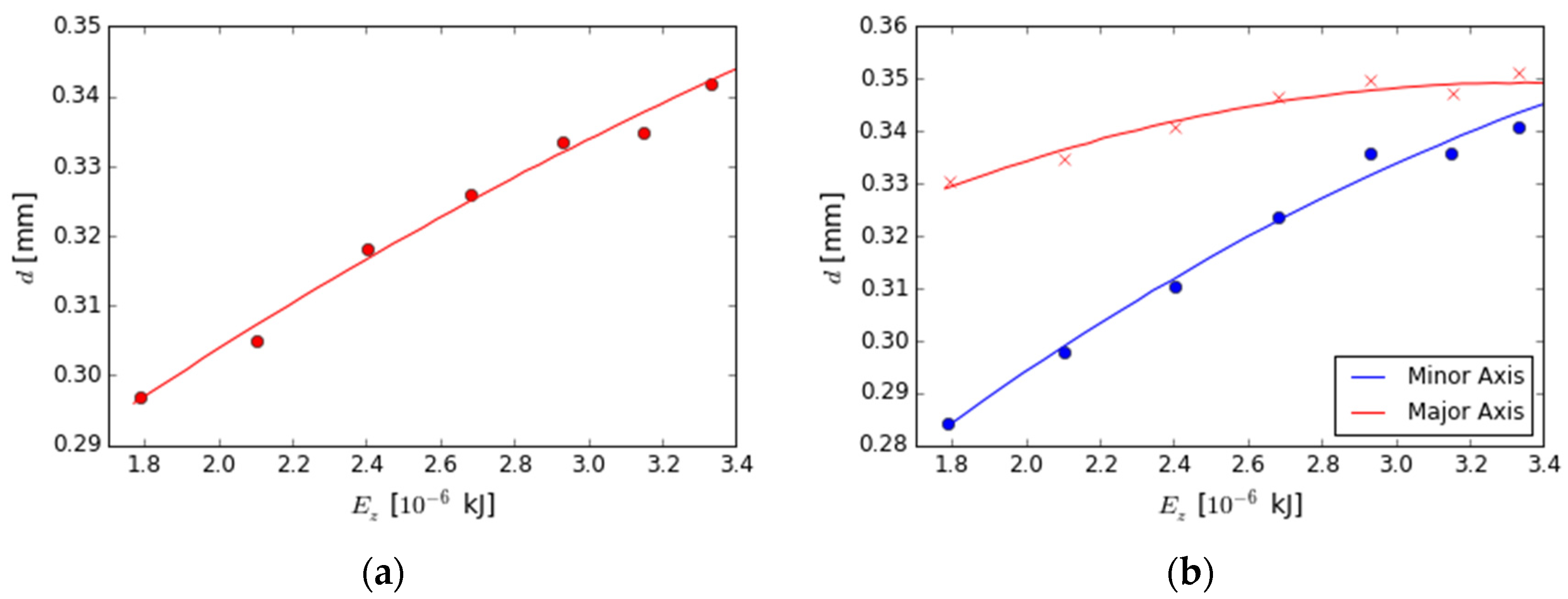
The variation of the ellipse major and minor axes for oblique impacts can be observed in Figure 2 as a function of the impact angle for a shot diameter of 0.6 mm and the impact velocity of 60 mm s−1. Hong et al. [22] confirmed that the highest residual stresses are obtained at angles closer to the vertical incident direction. In this study, angles higher than 45° were not taken into consideration, as they considerably reduce the desirable effects of the surface treatment and, in practice, are normally avoided. These results indicate that the ellipse diameter in the x-direction, that is, the direction of the horizontal component of the impact velocity, decreases more slowly compared to the diameter in the perpendicular axis. It is also observed that by increasing the impact angle, that is, reducing the vertical component of the velocity vector, the indent size and the amount of energy converted to plastic deformation decreases, reducing the subsequent residual stresses and work hardening effects. Figure 3 represents the relationship between the initial kinetic energy of the shot and the indent diameter considering steel shot and the perpendicular component of the velocity of the oblique impacts. A higher shot diameter naturally increases the indent size, but in the case of an oblique impact, the variations of the major and minor ellipse axis have different trends caused by the reduction of the vertical component of kinetic energy and the presence of a horizontal energy component.
4. Multiple Impact Model
We performed multiple impact analyses with a slightly reduced model size compared to the single impact (0.25 × 0.25 × 0.5 mm3) to moderate the computational costs without affecting the obtained distribution of residual stresses. This model is aimed at evaluating the effects of multiple inclined impacts with regard to the residual stress and PEEQ. In particular, we investigated the effects of the most significant parameters such as impact angle, shot diameter, shot velocity, and the required surface coverage.
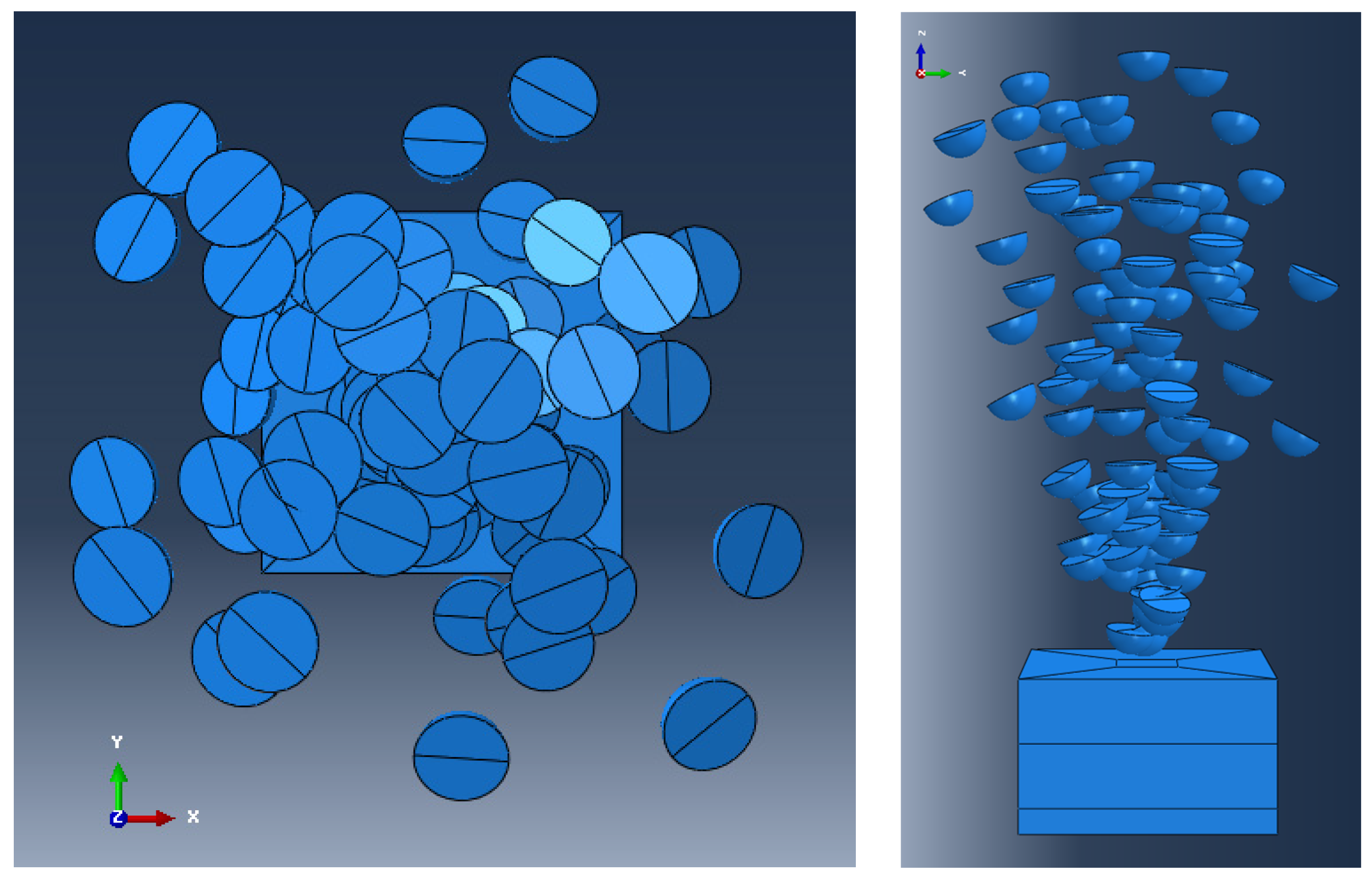
Random surface coverage in terms of the impact position and sequence was adopted following the subroutine previously developed by the authors of Reference [20] for a realistic simulation of surface coverage during the multiple-impact peening process. The subroutine that is based on the exponential Avrami approach for full coverage estimation [33], was updated incorporating the possibility of imposing random impact angle for each individual shot and estimating the corresponding indent elliptical area. Figure 4 represents the top and front view of the positioned multiple shots obtained from the implementation of the coverage subroutine.
Having defined all the details of the model, a Design of Experiment (DOE) method was adopted to determine the possible dependencies between the main peening parameters including shot diameter (d = 0.42, 0.06, 0.85 mm), shot velocity (v = 40, 50, 60, 70 m/s), impact angle (α = 0, 15, 30, 45°) and surface coverage (C = 100, 300, 500%). Considering the shots as elastic and neglecting the dissipation of thermal energy during shot peening, the energy that is absorbed for the plastic deformation of the target material can be extracted from the difference between the shot kinetic energy just before and after the impact. The deformation energy for a single vertical impact can be estimated by Equation (6), in which E is the kinetic energy, Vi is the initial velocity of the impact and Vr is the rebound energy.
In the case of an oblique impact, the variation of kinetic energy is influenced by both the vertical and horizontal components of the velocity, considering that the friction phenomena (characterized by Coulomb friction [34]), introduces a significant contribution. In particular, by increasing the incident angle, the horizontal component of velocity becomes comparable with the vertical one. This considers the dissipated energy caused by local sliding of the shot on the target surface. Therefore, the energy introduced into the process, in order to deform the surface of the component, is defined by considering both components of the shot velocity before and after impact and the total energy considered in the analysis is the sum of energy variation of all the impacting shots (Equation (7)).
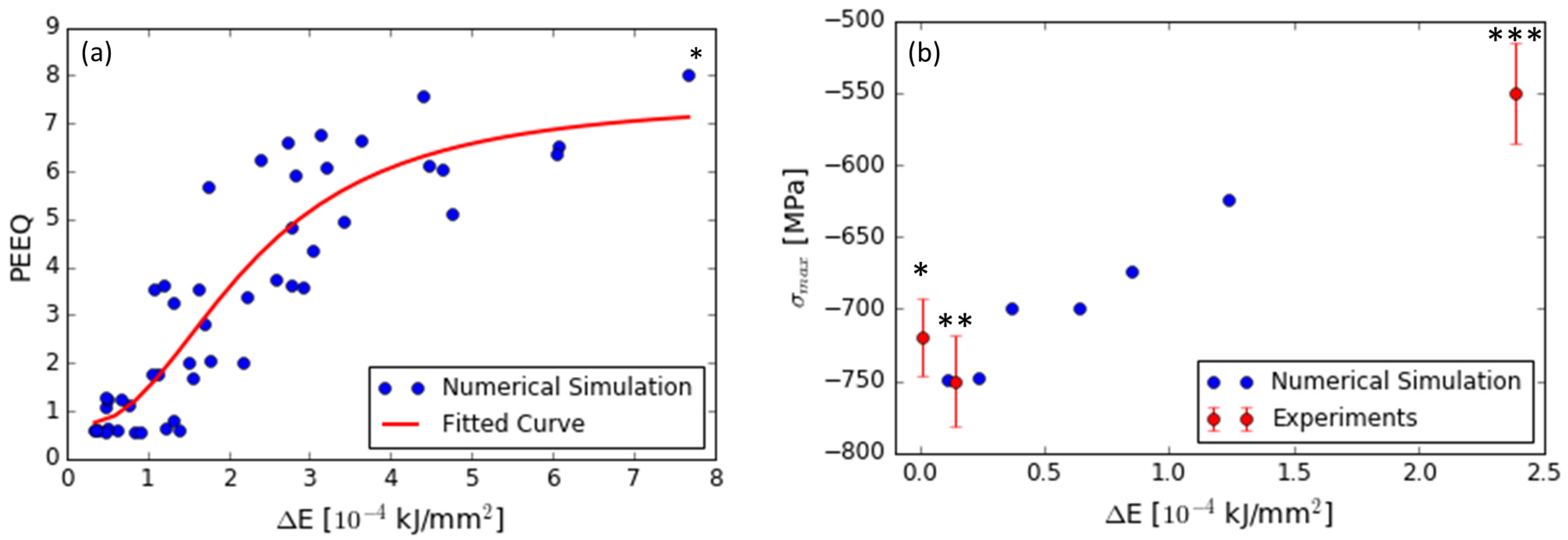
Figure 5 shows the trend of the average PEEQ on the surface layer of the target material for the multiple-impact model as a function of the transmitted kinetic energy per unit area (the transmitted kinetic energy is normalized by the total impact area). One analysis performed with a shot diameter of 0.85 mm, a vertical velocity of 70 m s−1, and a surface coverage of 800% (much higher compared to the range used in the DOE analysis) is added to consider the case of an SSP that is aimed at surface nanocrystallization. The results indicate a clear initial increase of the PEEQ as the transmitted kinetic energy is increased. For much higher impact kinetic energies, however, the PEEQ values tend to grow much more gradually, as it can be observed for the SSP case. From the analysis presented here, it is possible to determine the formula (Equation (8)), which allows us to obtain the value of the PEEQ as a function of the energy normalized per impact surface area, with an acceptable fit.
In order to validate this energetic approach, we needed to compare its results with some experimental data on materials for which we have access to all the experimental details in terms of process parameters and measured residual stresses in order to be able to calculate the kinetic energy of the impacts. The experimental data presented here are obtained from our previous experiments performed on two low alloy steels 39NiCrMo3 (UNI EN 10083) [11] and 40NiCrMo7 (UNI 7845)) [35]. Table 1 reports the general mechanical properties of these two steels. Numerical models were developed using a range of process parameters covering the ones used in the aforementioned experiments and incorporating the Chaboche material properties of the corresponding steel. Figure 5b represents the comparison of the available experimental data and the numerical ones, where a good correspondence can be observed.
5. Conclusions
An energetic approach was suggested to substitute the combined use of various process parameters in impact-based surface treatments including Almen intensity and surface coverage, as well as the size and material properties of the shots. This approach is based on the portion of the normalized kinetic energy used up for plastic deformation of the target surface.
The obtained finite element results indicate that equivalent plastic strain is highly correlated with the normalized kinetic energy of the impacts. This energy parameter can be adopted to estimate the effect of impact-based surface treatments on the treated material in terms of equivalent plastic deformation and residual stresses. As a proof of concept, the validity of this method was evaluated using experimental data for which all the necessary input parameters for the simulation were available. Comparison with experimental data points out that kinetic energy has a high potential to substitute other process parameters and provide a good estimation of the residual stress state. This method can be considered the first step toward developing a purely energetic approach. However, more controlled experiments covering a wide range of parameters would be needed to thoroughly verify the applicability of this approach.
Author Contributions
R.G., M.G., and S.B. conceived the idea and designed the methodology; R.G. and G.C. developed the finite element analysis; R.G., G.C., and S.B. analyzed the data; R.G. and S.B. wrote the paper. All the authors reviewed and provided comments on the manuscript.
Conflicts of Interest
The authors declare no conflicts of interest.
References
- Bagheri, S.; Guagliano, M. Review of shot peening processes to obtain nanocrystalline surfaces in metal alloys. Surf. Eng. 2009, 25, 3–14. [Google Scholar] [CrossRef]
- Bagherifard, S.; Hickey, D.J.; de Luca, A.C.; Malheiro, V.N.; Markaki, A.E.; Guagliano, M. The influence of nanostructured features on bacterial adhesion and bone cell functions on severely shot peened 316L stainless steel. Biomaterials 2015, 73, 185–197. [Google Scholar] [CrossRef] [PubMed]
- Bagherifard, S.; Ghelichi, R.; Khademhosseini, A.; Guagliano, M. Cell response to nanocrystallized metallic substrates obtained through severe plastic deformation. ACS Appl. Mater. Interfaces 2014, 6, 7963–7985. [Google Scholar] [CrossRef] [PubMed]
- Bagherifard, S.; Hickey, D.J.; Fintová, S.; Pastorek, F.; Fernandez-Pariente, I.; Bandini, M. Effects of nanofeatures induced by severe shot peening (SSP) on mechanical, corrosion and cytocompatibility properties of magnesium alloy AZ31. Acta Biomater. 2018, 66, 93–108. [Google Scholar] [CrossRef] [PubMed]
- Bagherifard, S.; Beretta, N.; Monti, S.; Riccio, M.; Bandini, M.; Guagliano, M. On the fatigue strength enhancement of additive manufactured AlSi10Mg parts by mechanical and thermal post-processing. Mater. Des. 2018, 145, 28–41. [Google Scholar] [CrossRef]
- Liu, Z.; Fecht, H.; Umemoto, M. Microstructural evolution and nanocrystal formation during deformation of Fe–C alloys. Mater. Sci. Eng. A 2004, 375, 839–843. [Google Scholar] [CrossRef]
- Rakita, M.; Wang, M.; Han, Q.; Liu, Y.; Yin, F. Ultrasonic shot peening. Int. J. Comput. Mater. Sci. Surf. Eng. 2013, 5, 189–209. [Google Scholar] [CrossRef]
- Liu, G.; Wang, S.; Lou, X.; Lu, J.; Lu, K. Low carbon steel with nanostructured surface layer induced by high-energy shot peening. Scr. Mater. 2001, 44, 1791–1795. [Google Scholar] [CrossRef]
- Lu, K.; Lu, J. Nanostructured surface layer on metallic materials induced by surface mechanical attrition treatment. Mater. Sci. Eng. A 2004, 375, 38–45. [Google Scholar] [CrossRef]
- Zhang, H.; Hei, Z.; Liu, G.; Lu, J.; Lu, K. Formation of nanostructured surface layer on AISI 304 stainless steel by means of surface mechanical attrition treatment. Acta Mater. 2003, 51, 1871–1881. [Google Scholar] [CrossRef]
- Tong, W.; Tao, N.; Wang, Z.; Lu, J.; Lu, K. Nitriding iron at lower temperatures. Science 2003, 299, 686–688. [Google Scholar] [CrossRef] [PubMed]
- Heydari Astaraee, A.; Miresmaeili, R.; Bagherifard, S.; Guagliano, M.; Aliofkhazraei, M. Incorporating the principles of shot peening for a better understanding of surface mechanical attrition treatment (SMAT) by simulations and experiments. Mater. Des. 2017, 116, 365–373. [Google Scholar] [CrossRef]
- Dai, K.; Shaw, L. Comparison between shot peening and surface nanocrystallization and hardening processes. Mater. Sci. Eng. A 2007, 463, 46–53. [Google Scholar] [CrossRef]
- Bagherifard, S.; Ghelichi, R.; Guagliano, M. A numerical model of severe shot peening (SSP) to predict the generation of a nanostructured surface layer of material. Surf. Coat. Technol. 2010, 204, 4081–4090. [Google Scholar] [CrossRef]
- Bagherifard, S.; Slawik, S.; Fernández-Pariente, I.; Pauly, C.; Mücklich, F.; Guagliano, M. Nanoscale surface modification of AISI 316L stainless steel by severe shot peening. Mater. Des. 2016, 102, 68–77. [Google Scholar] [CrossRef]
- Wang, X.Y.; Li, D.Y. Mechanical and electrochemical behavior of nanocrystalline surface of 304 stainless steel. Electrochim. Acta 2002, 47, 3939–3947. [Google Scholar] [CrossRef]
- Roy, S.; Fisher, J.W.; Yen, B.T. Fatigue resistance of welded details enhanced by ultrasonic impact treatment (UIT). Int. J. Fatigue 2003, 25, 1239–1247. [Google Scholar] [CrossRef]
- Mordyuk, B.N.; Prokopenko, G.I. Ultrasonic impact peening for the surface properties’ management. J. Sound Vib. 2007, 308, 855–866. [Google Scholar] [CrossRef]
- Almen, J.; Black, P.; Dolan, T. Residual Stresses and Fatigue in Metals. J. Appl. Mech. 1964, 31, 368. [Google Scholar] [CrossRef]
- Bagherifard, S.; Ghelichi, R.; Guagliano, M. On the shot peening surface coverage and its assessment by means of finite element simulation: A critical review and some original developments. Appl. Surf. Sci. 2012, 259, 186–194. [Google Scholar] [CrossRef]
- Guagliano, M. Relating Almen intensity to residual stresses induced by shot peening: A numerical approach. J. Mater. Process. Technol. 2001, 110, 277–286. [Google Scholar] [CrossRef]
- Hong, T.; Ooi, J.Y.; Shaw, B. A numerical simulation to relate the shot peening parameters to the induced residual stresses. Eng. Fail. Anal. 2008, 15, 1097–1110. [Google Scholar] [CrossRef]
- Franchim, A.S.; de Campos, V.S.; Travessa, D.N.; de Moura Neto, C. Analytical modelling for residual stresses produced by shot peening. Mater. Des. 2009, 30, 1556–1560. [Google Scholar] [CrossRef]
- Mylonas, G.I.; Labeas, G. Numerical modelling of shot peening process and corresponding products: Residual stress, surface roughness and cold work prediction. Surf. Coat. Technol. 2011, 205, 4480–4494. [Google Scholar] [CrossRef]
- Bagherifard, S.; Ghelichi, R.; Guagliano, M. Numerical and experimental analysis of surface roughness generated by shot peening. Appl. Surf. Sci. 2012, 258, 6831–6840. [Google Scholar] [CrossRef]
- Herzog, R.; Zinn, W.; Scholtes, B.; Wohlfahrt, H. The significance of Almen intensity for the generation of shot peening residual stresses. Materialwiss. Werkstofftech. 1996, 27, 608–617. [Google Scholar] [CrossRef]
- Miao, H.Y.; Larose, S.; Perron, C.; Lévesque, M. An analytical approach to relate shot peening parameters to Almen intensity. Surf. Coat. Technol. 2010, 205, 2055–2066. [Google Scholar] [CrossRef]
- Zakavi, S.J.; Zehsaz, M.; Eslami, M.R. The ratchetting behavior of pressurized plain pipework subjected to cyclic bending moment with the combined hardening model. Nucl. Eng. Des. 2010, 240, 726–737. [Google Scholar] [CrossRef]
- Bagherifard, S.; Ghelichi, R.; Guagliano, M. Mesh sensitivity assessment of shot peening finite element simulation aimed at surface grain refinement. Surf. Coat. Technol. 2014, 243, 58–64. [Google Scholar] [CrossRef]
- Kirk, D. Prediction and Control of Indent Diameter. In The Shot Peener; 2004; pp. 18–21. [Google Scholar]
- Kirk, D. Peening indent dimensions. In The Shot Peener; 2010; pp. 24–32. [Google Scholar]
- Iida, K. Dent and affected layer produced by shot peening. In The Shot Peener; 2000; pp. 4–7. [Google Scholar]
- Kirk, D.; Abyaneh, M. Theoretical basis of shot peening coverage control. The Shot Peener, 1995; 28–30. [Google Scholar]
- Frija, M.; Hassine, T.; Fathallah, R.; Bouraoui, C.; Dogui, A. Finite element modelling of shot peening process: Prediction of the compressive residual stresses, the plastic deformations and the surface integrity. Mater. Sci. Eng. A 2006, 426, 173–180. [Google Scholar] [CrossRef]
- Bagherifard, S.; Fernandez-Pariente, I.; Ghelichi, R.; Guagliano, M. Fatigue behavior of notched steel specimens with nanocrystallized surface obtained by severe shot peening. Mater. Des. 2013, 45, 497–503. [Google Scholar] [CrossRef]
Figure 1.
Comparison of the indent size diameter and depth estimated by the emperical equations of Kirk and Iida with the data obtained from the single impact finite element model (FEM) analysis (vertical impact, shot diameter: 0.6 mm, shot density: 7800 kg m−3, Brinell hardness: 201 HB); the inserts are representative vertical displacement contours; the stress range corresponds to both inserts.
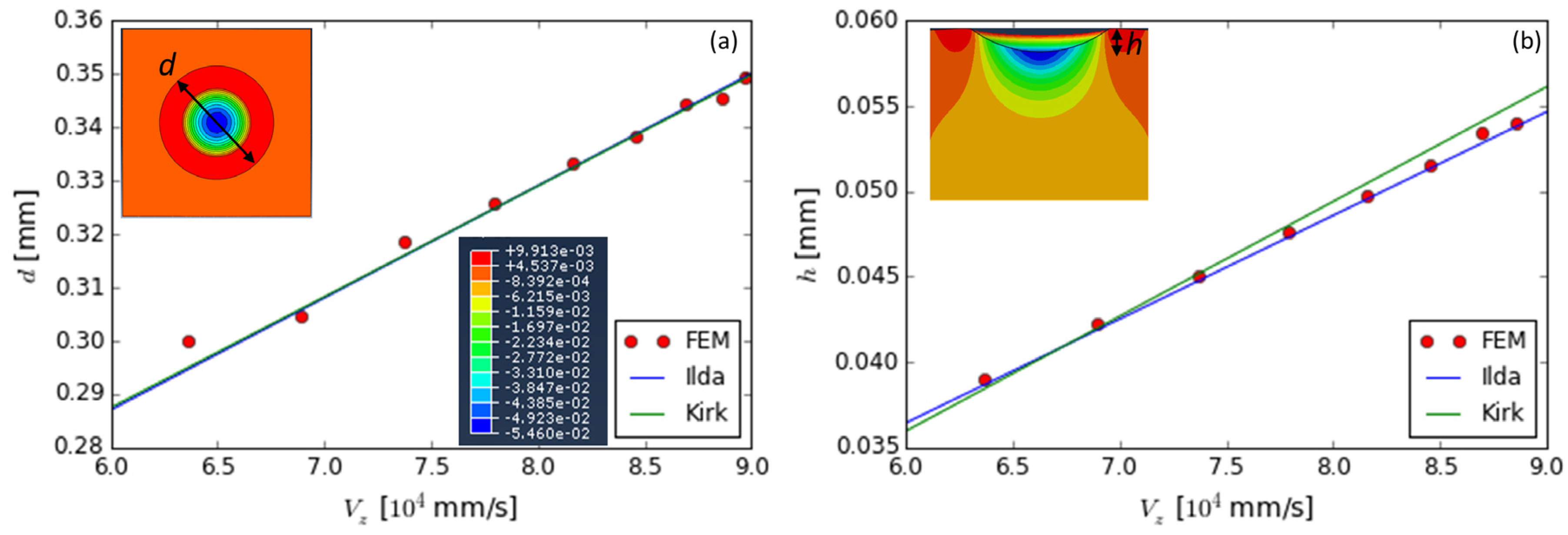
Figure 2.
(a) Different views of the elliptical indent generated by an oblique impact represented in vertical displacement contours. The prediction of ellipse indent size for oblique impacts (shot diameter = 0.6 mm, shot velocity = 60 mm s−1) obtained from the single impact FEM analysis; (b) major and minor axis; (c) ellipse max depth.
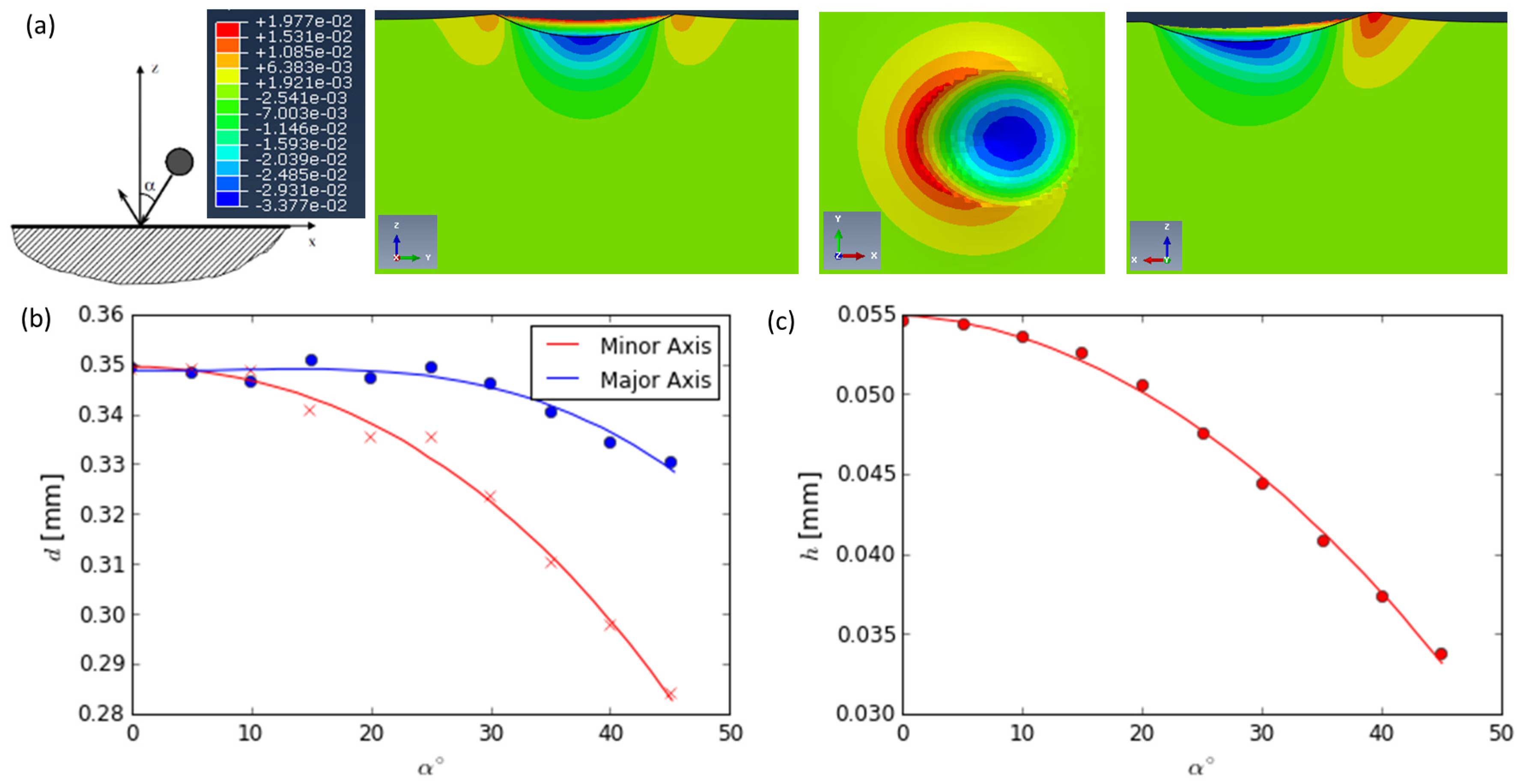
Figure 3.
The variation of the dimple diameter as a function of the vertical component of the shot kinetic energy (a) perpendicular impact; (b) oblique impact (shot diameter = 0.6 mm, shot velocity = 60 mm s−1).
Figure 3.
The variation of the dimple diameter as a function of the vertical component of the shot kinetic energy (a) perpendicular impact; (b) oblique impact (shot diameter = 0.6 mm, shot velocity = 60 mm s−1).

Figure 4.
The top and side view of the randomly positioned multiple impact model.

Figure 5.
(a) The surface variation of equivalent plastic strain (PEEQ) in the multiple impact model as a function of the kinetic energy per unit area (the topmost data point on the left represents severe shot peening cases); (b) the max in-depth residual stress obtained by FEM compared with comparted experimental data (* corresponds to experimental data for 40NiCrMo7 (shot size 0.3 mm, Almen intensity 4–6 A (0.0001 in.) and 100% coverage); ** corresponds to experimental data for 40NiCrMo7 (shot size 0.43 mm, Almen intensity 10–12 A (0.0001 in.) and 100% coverage); *** corresponds to experimental data for 39NiCrMo3 (shot size 0.6 mm, Almen intensity 7C (0.0001 in.) and 1500% coverage)).


Table 1.
General mechanical properties of 39NiCrMo3 and 40NiCrMo7 steel.
| Steel | Elastic Modulus (GPa) | Yield Modulus (MPa) | Ultimate Tensile Stress (MPa) | Elongation (%) |
|---|---|---|---|---|
| 39NiCrMo3 | 210 | 734 | 908 | 14.8 |
| 40NiCrMo7 | 203 | 1170 | 1290 | 14.9 |
© 2018 by the authors. Licensee MDPI, Basel, Switzerland. This article is an open access article distributed under the terms and conditions of the Creative Commons Attribution (CC BY) license (http://creativecommons.org/licenses/by/4.0/).
Share and Cite
MDPI and ACS Style
Ghelichi, R.; Crispiatico, G.; Guagliano, M.; Bagherifard, S. An Energetic Approach to Predict the Effect of Shot Peening-Based Surface Treatments. Metals 2018, 8, 190. https://doi.org/10.3390/met8030190
AMA Style
Ghelichi R, Crispiatico G, Guagliano M, Bagherifard S. An Energetic Approach to Predict the Effect of Shot Peening-Based Surface Treatments. Metals. 2018; 8(3):190. https://doi.org/10.3390/met8030190
Chicago/Turabian StyleGhelichi, Ramin, Giorgio Crispiatico, Mario Guagliano, and Sara Bagherifard. 2018. "An Energetic Approach to Predict the Effect of Shot Peening-Based Surface Treatments" Metals 8, no. 3: 190. https://doi.org/10.3390/met8030190
Note that from the first issue of 2016, this journal uses article numbers instead of page numbers. See further details here.