Numerical Study on the Influence of a Swirling Flow Tundish on Multiphase Flow and Heat Transfer in Mold
by

Peiyuan Ni
1,2,*, 
Mikael Ersson
3, 
Lage Tord Ingemar Jonsson
3,
Ting-an Zhang
1 and
Pär Göran JÖNSSON
3 1
Key Laboratory of Ecological Metallurgy of Multi-metal Intergrown Ores of Education Ministry, School of Metallurgy, Northeastern University, Shenyang 110819, China
2
Department of Materials and Manufacturing Science, Graduate School of Engineering, Osaka University, 2-1 Yamadaoka, Suita, Osaka 565-0871, Japan
3
Department of Materials Science and Engineering, KTH Royal Institute of Technology, SE-100 44 Stockholm, Sweden
*
Author to whom correspondence should be addressed.
Metals 2018, 8(5), 368; https://doi.org/10.3390/met8050368
Submission received: 30 April 2018
/
Revised: 11 May 2018
/
Accepted: 18 May 2018
/
Published: 21 May 2018
(This article belongs to the Special Issue Continuous Casting)
Abstract
:The effect of a new cylindrical swirling flow tundish design on the multiphase flow and heat transfer in a mold was studied. The RSM (Reynolds stress model) and the VOF (volume of fluid) model were used to solve the steel and slag flow phenomena. The effect of the swirling flow tundish design on the temperature distribution and inclusion motion was also studied. The results show that the new tundish design significantly changed the flow behavior in the mold, compared to a conventional tundish casting. Specifically, the deep impingement jet from the SEN (Submerged Entry Nozzle) outlet disappeared in the mold, and steel with a high temperature moved towards the solidified shell due to the swirling flow effect. Steel flow velocity in the top of the mold was increased. A large velocity in the vicinity of the solidified shell was obtained. Furthermore, the risk of the slag entrainment in the mold was also estimated. With the swirling flow tundish casting, the temperature distribution became more uniform, and the dissipation of the steel superheat was accelerated. In addition, inclusion trajectories in the mold also changed, which tend to stay at the top of the mold for a time. A future study is still required to further optimize the steel flow in mold.
1. Introduction
The mold is the final stage during the continuous casting process of steel, where the solidification of the molten steel occurs. Multiphase flow, heat and mass transfer, slag entrainment, inclusion and bubble entrapment, inclusion removal, and solidification are very important multiphysics concerns in the continuous casting process. This is due to the fact that these issues can significantly influence the quality of the semifinal steel product. As a matter of the first importance, a desirable steel flow in mold is wanted, since the other physical phenomena are directly affected by the steel flow inside the mold.
Direct investigations of the flow phenomena in a mold face significant challenges, due to the high temperature and high cost. Therefore, as an initial step to further improve the steel flow performance in a mold, numerical and physical modeling has become a common way to study the multiphase flow phenomena under various conditions. Specifically, some factors that may affect the mold flow, such as the SEN (Submerged Entry Nozzle) type (straight or bifurcated) [1,2], SEN port design (shape, angle, thickness) [3,4,5,6,7,8,9,10], argon bubbles [11,12,13,14,15,16,17,18,19,20,21,22,23], SEN immersion depth [3,4,6,24], nozzle clogging [25], mold flow modifier [26], EMBr (electromagnetic braking) [13,14,20,21,22,23,24,27,28,29,30] and M-EMS (mold electromagnetic stirring) [8,9,10,31], have been vastly investigated. Further improvements of the steel flow performance simply based on the parameter optimization become difficult. Therefore, in recent years, EMBr and M-EMS are widely applied to improve the steel flow performance in mold. It was found that EMBr can reduce the flow variation [23], suppress the flow velocity [20,30], increase the temperature near meniscus [14,29], decrease the temperature difference in mold [20,29], and reduce the impingement intensity near the narrow wall [29]. The use of M-EMS was found to contribute to a uniform temperature distribution [10,31], a large floating up rate of inclusions [31,32], a homogeneous solute distribution [10], a uniform solidified shell [10], and a high quality of the steel product [32]. However, their application relies on costly equipment, and also requires the consumption of electricity. Furthermore, it is sometimes difficult to realize a good flow pattern in a mold, since the original upstream flows from the SEN ports are unknown, due to flow fluctuations or biased flows. In addition, the effects of EMBr are directly related to some factors, such as the intensity of the magnetic field, the reciprocal position between the magnetic field and the acting region, the casting speed, the SEN depth, and so on [24,30]. Also, for the M-EMS case, the meniscus velocity magnitude and the level fluctuation height were found roughly linearly proportional to the applied current [33]. Therefore, over-stirring or insufficient stirring should be avoided, which sometimes is difficult, due to the transient steel flow in a real casting situation. Furthermore, it takes some time for the M-EMS to change the steel flow from a single port SEN in a billet or bloom casting, due to the high momentum of the impingement jet flow going deep into the mold. In summary, the performances of EMBr and M-EMS highly depend on the SEN port flow situation and application parameters. This leads to some uncertainties of their performances in applications.
An alternative way to optimize the mold flow is by a root measure to control the SEN outlet flow. This is realized by using a swirling flow SEN, which aims to produce a rotational flow component to optimize the SEN port flows, and afterwards, optimize the steel flow in a mold. The swirling flow SEN and its influence on the mold flow have been vastly studied [34,35,36,37,38,39,40,41,42,43,44,45,46]. It was found that the heat and mass transfer near the meniscus can be remarkably activated [34,38,40,42], and a uniform velocity distribution can be obtained within a short distance from the SEN outlet [34,38,40]. Furthermore, the penetration depth of the SEN outlet flow is remarkably decreased in a billet mold [34,42]. Industrial trial results [39] show that the swirling flow SEN effectively improved the steel product quality and reduced the clogging problem of the SEN side ports. Therefore, the swirling flow SEN has advantages in the continuous casting process.
In the past, several methods were studied both experimentally and numerically to produce a swirling flow inside a SEN. Specifically, a swirl blade method was investigated in many studies, where a swirling flow was produced by installing a swirl blade inside the SEN. It is a cost-saving method, and has been proved by plant trials [39] that it can improve the steel product quality. However, the lifespan of the swirl blade and the inclusion attachment on its surface, which may lead to nozzle clogging, restrict its application for longer casting times. Some studies have also been carried out to investigate the electromagnetic stirring method [43,44,45,46]. The swirling flow is obtained by installing the electromagnetic stirring equipment surrounding the SEN. Therefore, it is associated with an equipment cost and an electricity cost, which increases the steel product cost. Recently, Ni et al. [47,48,49] proposed a new method to produce a swirling flow in a SEN simply by using a cylindrical tundish design. It is a simple and cost-saving method to realize a swirling flow in the SEN. Furthermore, its effectiveness has been confirmed both by water model experiments, and also by numerical simulations [49]. However, the steel flow characteristics in the mold with this new tundish design remains to be studied.
Previous studies about the influence of a swirling flow SEN on the mold flow commonly ignored the top slag phase in the mold. The influence of a swirling flow SEN on the steel-slag interface phenomena and the steel flow in the vicinity of the solidified shell should be further studied. Moreover, swirling steel flows, produced from M-EMS and the swirling SEN, were mainly investigated by using k-ε type of turbulence models. However, high-intensity swirling flows normally have anisotropic turbulent fluctuations, and sometimes, a vortex core precession exists in this kind of flows [50]. A RSM (Reynolds Stress Model) which directly solves the anisotropic turbulent fluctuations shows better performance, in general, compared to the RANS eddy-viscosity models [49,51,52,53]. Jakirlic et al. [53] also found that a good ability to capture the stress anisotropy in the near-wall region is very important to reproduce these types of flow. Therefore, the swirling steel flow in a cylindrical tundish design has previously been solved by using RSM coupled with the Stress-Omega submodel, where the turbulent boundary layer was also resolved with a very fine grid (y+ < 1) [49]. In this study, the characteristics of the multiphase flow and heat transfer in a billet mold were studied during the casting process by using the new swirling flow tundish design. The swirling flow velocity profile on a cross section of the SEN obtained in the previous study [49] was used as the inlet flow condition for the mold flow solution to save the computational time. The RSM coupled with the Stress-Omega submodel was thereafter used to solve the flow in the mold, with a very fine grid near the solidified shell of y+ value around 1. The VOF (volume of fluid) method was used to capture the steel-slag interface. The energy equation was solved to study the temperature distribution in the mold, and a Lagrangian particle tracking scheme was used to study the motions of non-metallic inclusions in the mold. The fluid flow, steel-slag interface fluctuation, temperature distribution, and inclusion motion in the mold were investigated. In addition, to show the change of the multiphysics in the mold, these characteristics were compared to those in a conventional tundish casting without a swirling flow effect.
2. Model Description
2.1. Model Assumptions
A three-dimensional mathematical model has been developed to describe the steel-slag-inclusion three-phase flow, and the temperature distribution in the mold. The model is based on the following assumptions:
- Steel and slag behave as an incompressible Newtonian fluids;
- Solidification in the mold is not considered;
- A constant molecular viscosity for steel and slag was assumed. This is due to that the maximum temperature difference in the mold is only 30 K between 1788 K and 1818 K. The viscosity change in this temperature range is not significant, and this can be seen from a previous study [10];
- A constant steel and slag density was used. The temperature influence on the steel density change was accounted for in the source term of the momentum equation;
- The SEN wall was assumed to be a smooth wall;
- Inclusions were assumed to be spherical.
2.2. Transport Equations
The conservation of a general variable φ within a finite control volume can be expressed as a balance among the various processes, which tends to increase or decrease the variable values. The conservation equations, e.g., continuity, volume fraction, momentum, turbulence equations, and energy equation can be expressed by the following general equation [54]:
where the first term on the left-hand side is the instantaneous change of φ with time, the second term on the left-hand side represents the transport due to convection, the first term on the right-hand side expresses the transport due to diffusion where Γφ is the diffusion coefficient with different values for different turbulence models, or the effective thermal conductivity. Furthermore, the second term on the right-hand side is the source term.
2.3. Interface Tracking
In order to investigate the steel-slag interface fluctuation, the steel-slag interface must be properly tracked. This is done by employing the VOF model [55], where a volume fraction equation for the slag phase was solved. The sum of the slag phase fraction αslag and the steel phase fraction αsteel is equal to 1. In addition, one set of momentum and energy equation was solved to obtain the predicted flow field in the mold. The mixed material properties in the grid cell, where the interface exists, are required by the momentum equation and can be calculated by the following equations:
2.4. Turbulence Modeling
As previously mentioned, one important concern about modeling the swirling flow is the anisotropic turbulent properties which commonly exist in high intensity swirling flows. Here, the RSM model [55,56,57] combined with the Stress-Omega submodel [55,58] was used to simulate the steel flow. The Stress-Omega submodel is good for modeling flows over the curved surfaces and swirling flows [55]. A near-wall treatment is automatically used to perform blending between the viscous sublayer and the logarithmic region [55]. In RSM model, the Reynolds stress terms emerging from the Reynolds averaging of Navier-Stokes equations are directly solved by resolving their transport equations to account for the possible anisotropic fluctuation in a swirling flow. In order to save the computational time, the realizable k-ε turbulence model [59], coupled with the enhanced wall treatment model [55], was first used to produce an initial flow field. Then, with this flow initialization, the RSM model calculation was carried out until a fully developed flow was obtained.
2.5. Heat Transfer
The temperature distribution in the mold was obtained by solving the following energy equation [55]:
where E is energy in the unit of J, k is the thermal conductivity with the unit of W/(m·K), cp is the specific heat capacity in J/(kg·K), μt is the turbulent viscosity, Prt is the turbulent Prandtl Number, ρ is fluid density in kg/m3, p is pressure in Pa, and T is temperature in K. The steel density change and subsequent natural convection due to temperature variance was accounted for by the Boussinesq model [60]. This model treats density as a constant value in all solved equations, except for the buoyancy in the momentum equation (it is normally put in the source term) as follows:
where ρo is the (constant) density of the liquid steel with the unit of kg/m3, To is the operating temperature in K, and β is the thermal expansion coefficient of the liquid steel. The thermal properties of the fluids and some parameters are shown in Table 1.
2.6. Lagrangian Particle Tracking Model
The inclusion velocity up was obtained by solving the following momentum equation, which has been introduced in detail in a previous study [61]:
where, on the right-hand side, the first term is the drag force, the second term is the force per unit inclusion mass due to gravity and buoyancy, the third term is the virtual mass force, the fourth term is the pressure gradient force, and the fifth term is the Saffman’s lift force [62,63]. Furthermore, u is the continuous-phase velocity, v is the kinematic viscosity of the fluid, dp is the diameter of an inclusion, ρf and ρp are the densities of the fluid and the inclusion, respectively. Furthermore, Sij and Slk are the deformation tensor, and η is a constant which is equal to 2.59 [63].
2.7. Boundary Conditions
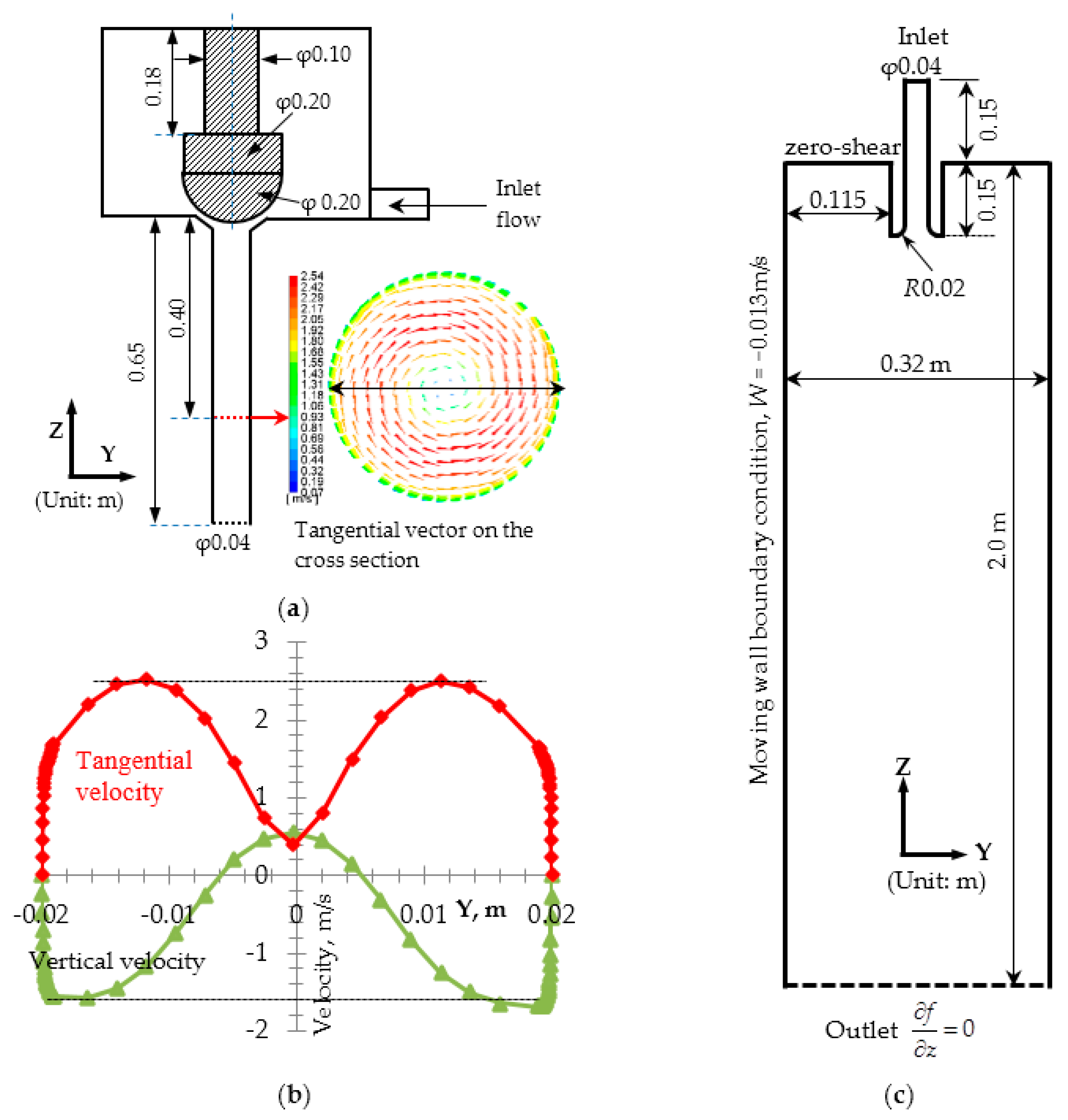
The velocity profile on the cross section of the cylindrical tundish SEN, which has been solved in a previous study [49], was used as the inlet boundary condition for the current simulation of the mold flow. Figure 1a,b show the location of the cross section on the cylindrical tundish SEN and the steel flow characteristics [49]. The cross section is located at 0.4 m below the tundish bottom with the total SEN length of 0.65 m. It can be seen that the maximum tangential velocity is around 2.5 m/s. The swirling number is defined by using the mean tangential velocity, W, and the mean vertical velocity, V, on the cross section with the ratio of 2W/3V, and it is 1.24 on this cross section [49]. The inlet boundary condition for the conventional tundish casting is a uniform velocity distribution at the SEN cross section, with the steel flow velocity of −1.1 m/s in Z-direction, which corresponds to the same casting speed as the swirling flow tundish casting.
The calculation domain is shown in Figure 1c. A non-slip boundary condition was imposed on the SEN wall. For the top surface of the mold, a zero-shear slip wall boundary condition was used. For the mold wall, a moving wall boundary condition with the velocity of −0.013 m/s in Z direction was used to account for the movement of the solidified shell in a real casting process. The fully developed flow condition is adopted at the mold outlet, where the normal gradients of all variables are set to zero. For the heat transfer boundary condition, a constant steel temperature of 1818 K was used at the inlet. A constant temperature of 1788 K was imposed on the solidified shell. An adiabatic condition was used both at the SEN wall and at the free surface. In addition, a “reflect” wall boundary condition was used for the inclusion tracking, and an “escape” boundary condition was used at the bottom outlet of the mold.
2.8. Solution Method
The multiphase flow and temperature distribution in the billet mold was solved by using the commercial software ANSYS FLUENT 18.0®. The numerical simulations were carried out based on 2.2 million grid cells to guarantee the grid-independent solution. A very fine grid was used in the near-wall region, with the y+ value of the first grid layer around 1. The PISO scheme was used for the pressure-velocity coupling. Furthermore, the PRESTO method was adopted to discretize the pressure. The governing equations were discretized using a second order upwind scheme. The convergence criteria were as follows: the residuals of all dependent variables were smaller than 1 × 10⁻³ at each time step.
3. Results and Discussion
The multiphase flow and heat transfer in the mold both with a swirling flow tundish casting and also with a conventional tundish casting were firstly solved by the realizable k-ε model with an enhanced wall treatment for the first 75 s. After that, this solution was used as an initial condition for the RSM model calculation to 125 s for a developed flow field. The multiphysics in the mold from a conventional tundish casting and from a swirling flow tundish casting were analyzed and compared in the following.
3.1. Steel Flow Paths
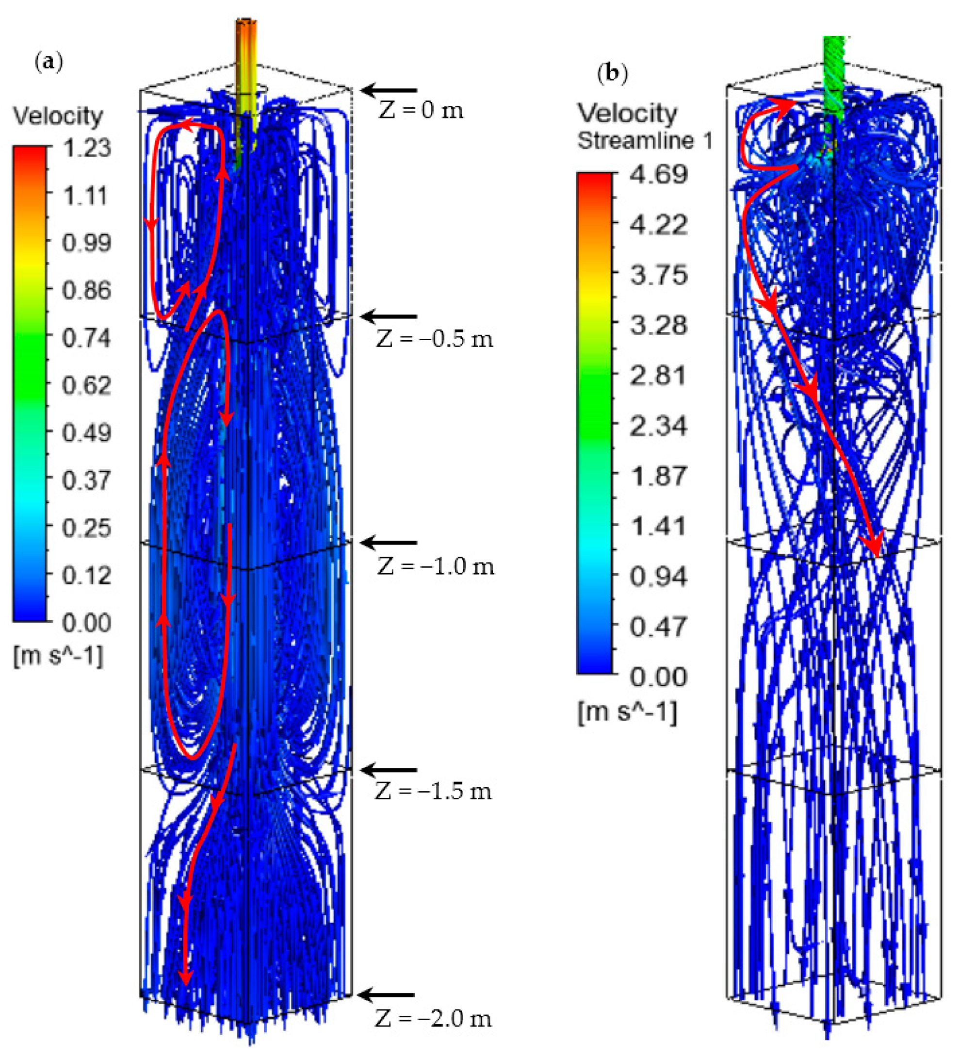
Figure 2 shows the steel flow path in the mold both from a conventional tundish and from a swirling flow tundish design. It can be observed that a completely different flow pattern in the mold was observed. With a conventional tundish casting in Figure 2a, the SEN outlet flow goes deep into the mold to the depth of around 1.5 m. This results from a large vertical momentum of the steel flow. As the steel flows downwards, the jet is entraining the surrounding fluid due to the friction. This dissipates the jet momentum and also increases the jet width. Meanwhile, the pressure in the region near the downward jet flow decreases. Therefore, the steel surrounding the impingement jet moves towards it. This leads to a vertical rotational flow in the middle region of the mold as shown in Figure 2a indicated by the red color arrows. The upwards steel flow in this rotational movement further leads to a weak rotational flow in the upper part of the mold near the meniscus. However, with a swirling flow tundish design in Figure 2b, the SEN outlet flow moves towards the solidified shell rather than goes deeply into the mold. This is due to the rotational steel flow momentum. After the steel stream reaches the solidified shell, a part of the steel flows downwards along the solidified shell with a horizontal rotational flow momentum, which can be seen from the red arrow in Figure 2b. Another part of the steel moves upwards and towards the meniscus. Therefore, the steel flow pattern undergoes a significant change compared to a conventional tundish casting. The deep impingement jet into the mold observed in Figure 2a disappeared with the use of a swirling flow tundish. This is also one of the advantages for the use of a swirling flow SEN compared to M-EMS. Due to the high steel flow inertia from the one-port SEN, the impingement jet was actually not significantly changed by the M-EMS, which shows a high downwards steel flow velocity in the center of the mold. This can be seen from some previous studies [32,33]. Therefore, in some cases, the side-port SEN was investigated in bloom castings in combination with M-EMS [8,10], which can change the high temperature SEN port flow towards the solidification front, rather than moving deeply into the mold. However, side ports are the sensitive region for nozzle clogging, and they deliver the steel into the mold from a certain direction depending on the SEN port direction, rather than along the periphery of the SEN, which is in 360° in a swirling flow SEN. Therefore, the current swirling flow tundish SEN can deliver high temperature steel uniformly distributed towards the solidified shell. Furthermore, this also avoids the strong attack by the high temperature steel on some locations of the solidified shell which is in the case with side ports.
3.2. Steel Flow Velocity
Figure 3 shows the steel flow velocity on the vertical planes at the middle of the mold. The locations of these vertical planes can be seen from the top view sketch of the mold in Figure 3. For all the vertical planes passing the mold center, the diagonal vertical plane is the largest vertical plane, and the plane perpendicular to the solid shell middle is the smallest vertical plane. Therefore, these planes are selected to show the flow characteristics. It can be seen in Figure 3a that the steel jet keeps a high velocity in the center of the mold, even for a large depth. At the top of the mold near the meniscus, the steel flow is very weak. However, with the swirling flow tundish as shown in Figure 3b, the high velocity region was located at the top region of the mold. This is expected to improve the heat transfer near the meniscus and the dissipation of the steel superheat. Furthermore, steel moves downwards at the region near the solidified shell, and it flows upwards in the center of the mold. This may be helpful to improve the mixing towards a homogeneous state in the mold. Furthermore, the velocity magnitude of the SEN outlet flow rapidly decreases to smaller than 0.4 m/s. As previously mentioned, there was no main impingement jet deep into the mold, which is different from the case of a conventional tundish casting with a straight SEN.
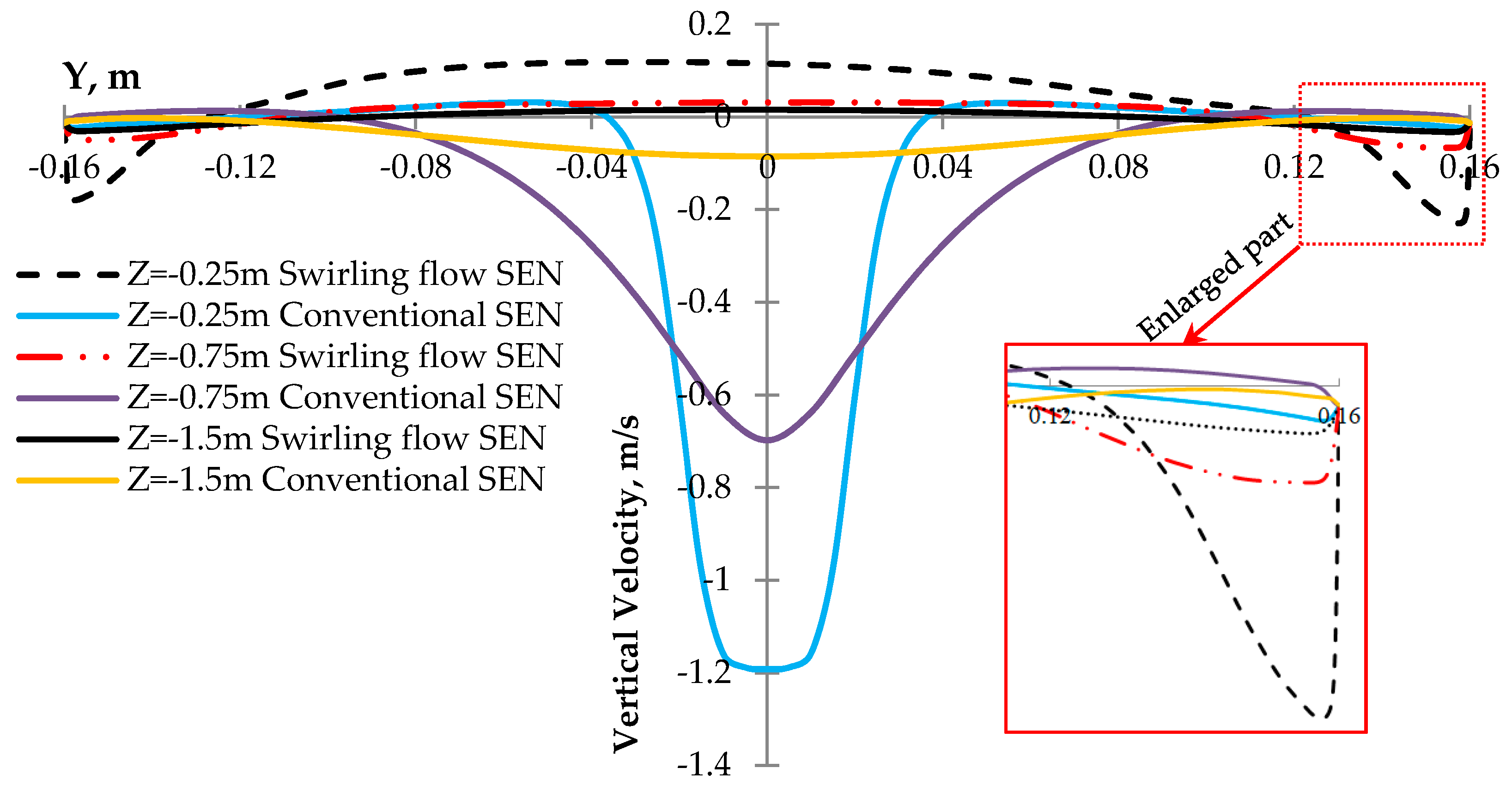
Figure 4 shows a comparison of the vertical velocity distributions along lines at different mold depths. It can be see that the vertical velocity magnitude is much smaller in the mold center when a swirling flow tundish design was used. This has been clearly shown in Figure 3b. However, at the locations close to the solidified shell, its velocity is larger than that with a conventional tundish casting. This can be seen from the enlarged part in Figure 4. A large velocity near the solidified shell is helpful to shear off the dendrites from the solidification interface and promotes the nucleate, which results in an enhancement of the transition from a columnar to an equiaxed solidification [33]. For the casting with a conventional tundish, the vertical velocity of the steel flow is still around 0.1 m/s at a depth of 1.5 m in the mold center. This kind of flow pattern, with a strong downwards flow stream, is not good for some issues in a steel continuous casting process, such as the inclusion removal and the dissipation of steel superheat. Therefore, it is clear that the swirling flow tundish design is helpful for the optimization of the mold flow.
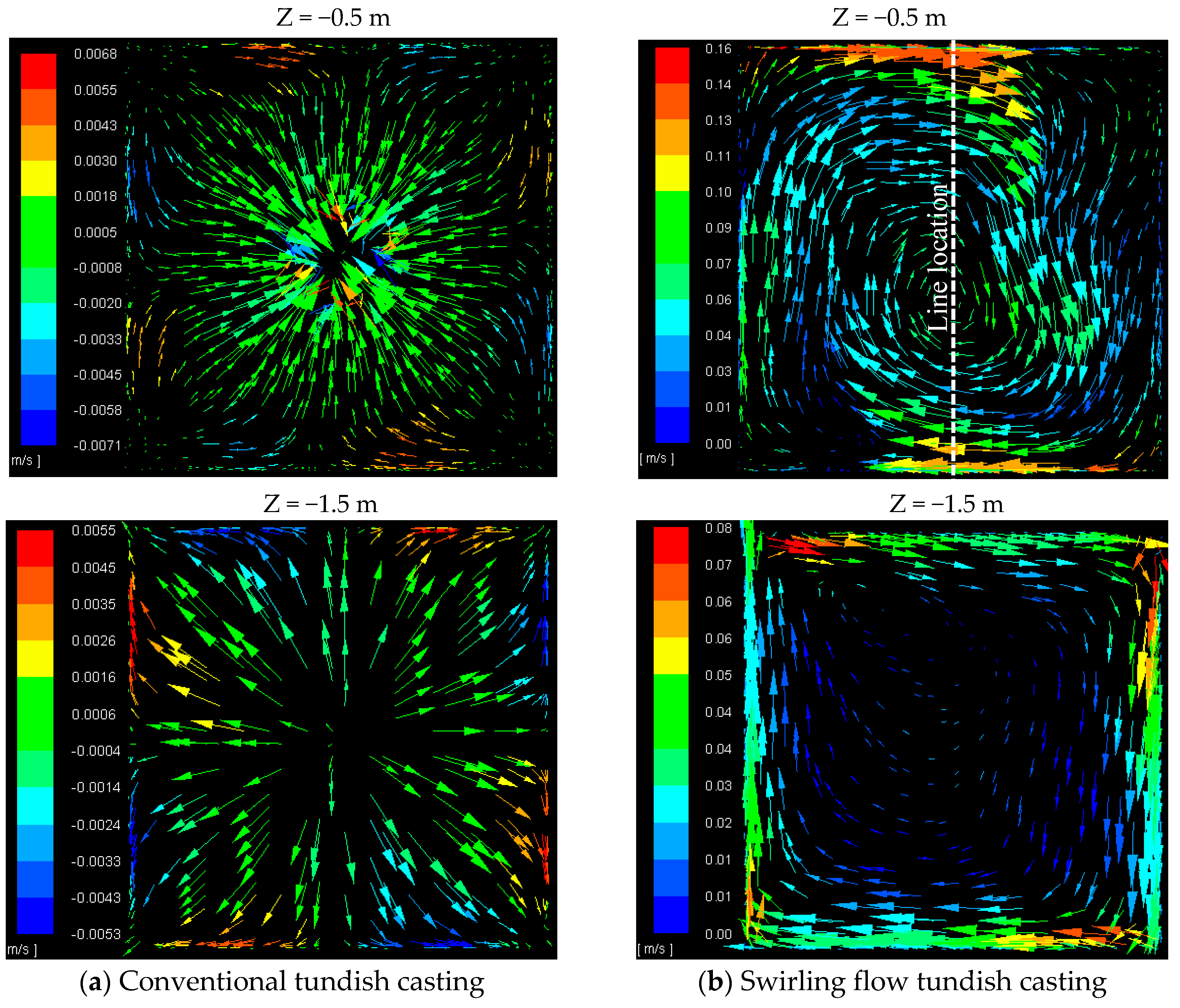
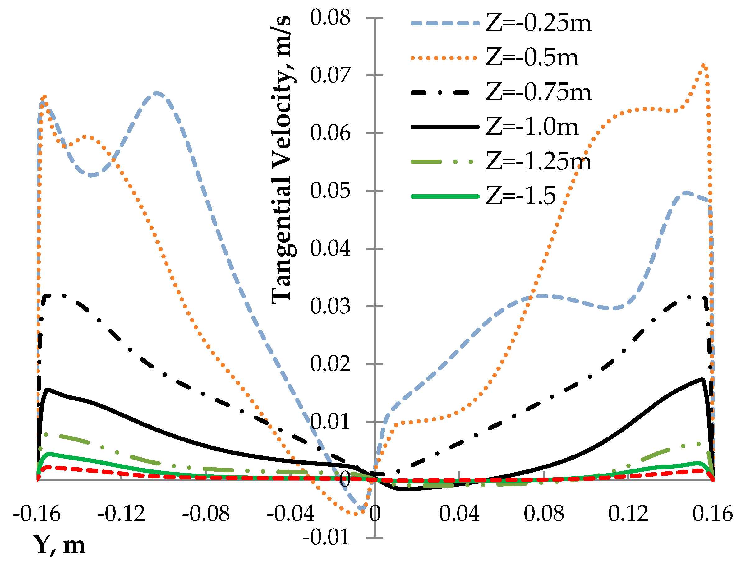
Another important characteristic about the swirling flow tundish casting is the swirling steel flow on the cross sections of the mold. Figure 5 shows the tangential velocities of the steel flow on two cross sections in different mold depths. It can be seen, in Figure 5b, that the maximum tangential velocity can reach around 0.076 m/s near the solidified shell on the cross section with a mold depth of 0.5 m. In addition, at a mold depth of 1.5 m, the maximum tangential velocity decreases to around 0.005 m/s, while the velocity distribution becomes more axisymmetric. This means that the swirling flow becomes more uniform after moving from the depth of 0.5 m to 1.5 m. Furthermore, the high tangential velocity region is still located near the solidified shell. Figure 6 shows the magnitude of the tangential velocity along different horizontal lines in different mold depths. The locations of the horizontal lines are shown in Figure 5b. It can be seen that the maximum tangential velocity gradually decreases when the steel moves downwards. This is similar as that in the mold with M-EMS, where the rotational velocity becomes smaller with an increased distance away from the stirrer midplane [33]. A large velocity gradient exists near the solidified shell, which can also be seen in Figure 4 for the vertical velocity component. In the mold with a conventional tundish, no obvious swirling flow was observed, and the steel flow velocity near the solidified shell is much smaller compared to the swirling flow tundish case. Therefore, both the tangential velocity magnitude and the axial velocity magnitude near the solidified shell are larger for the case with the swirling flow tundish casting than that with a conventional tundish casting.
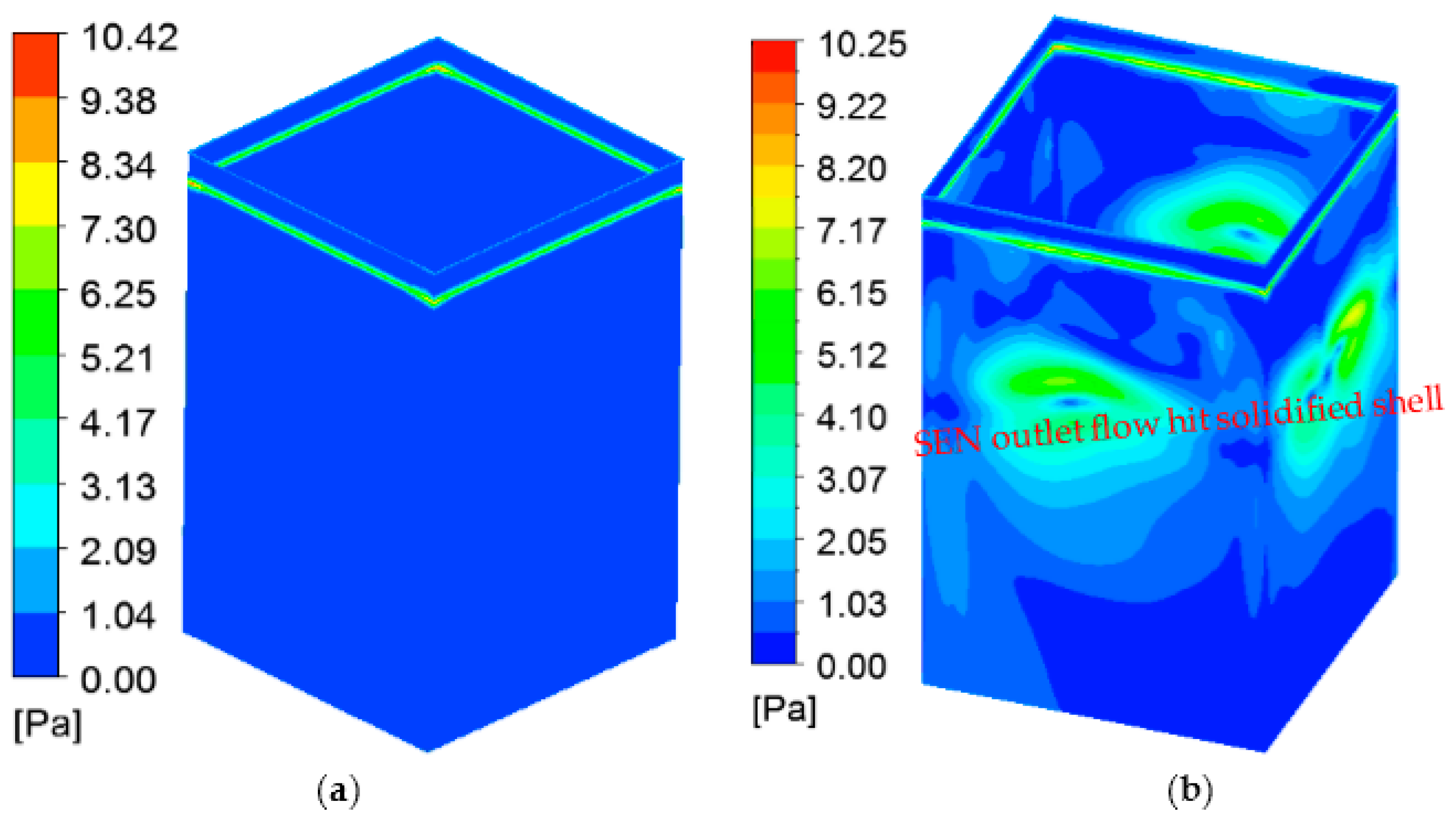
Due to the change of the steel flow pattern in mold, shear stresses on the solidified shell become different. Figure 7 shows the shear stress on the solidified shell for the first 0.5 m shell from the meniscus. It can be seen that the values of shear stresses are mostly smaller than 10 Pa both for the conventional tundish case and also for the swirling flow tundish case. Shear stress is proportional to the velocity gradient. Therefore, a large shear stress represents a large velocity gradient near the solidified shell. Due to that, a rotational flow exists in the mold as shown in Figure 5b, the shear stress values for the swirling flow tundish case are mostly larger than that with a conventional tundish. In addition, shear stresses at the locations where the SEN outlet flow hits the solidified shell are not very large, as shown in Figure 7b, with the values of around 6 Pa. This means that there is no strong flow stream towards the solidified shell, due to the uniformly spreading of the steel flow from the SEN outlet.
3.3. Turbulence Properties
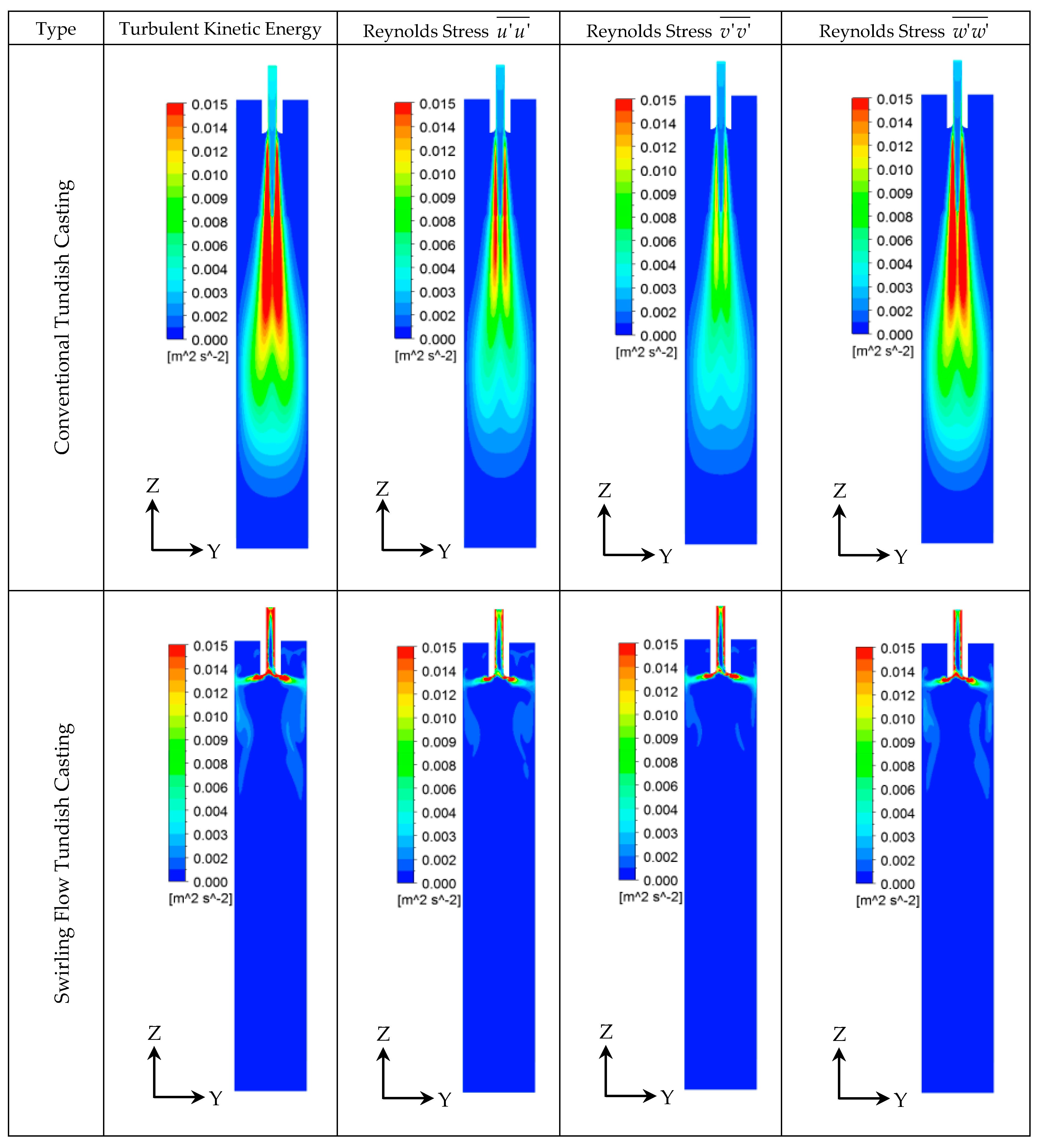
Due to the flow changes as presented above, the characteristics of the turbulence properties in the mold are also significantly changed, as shown in Figure 8. It can be seen that with a conventional tundish casting, the turbulence properties show jet flow characteristics. A high turbulent kinetic energy and Reynolds stress values exist in the region near the impingement jet, due to the shear between the jet and its surrounding steel. However, at the top of the mold, the magnitudes of the turbulence properties are very small. In addition, the turbulence properties show anisotropic characteristics. The Reynolds stress is large in the vertical direction, namely, the value of in the conventional tundish casting. With a swirling flow tundish casting, turbulence properties are sharply dissipated in the top region of the mold. This is due to the change of the steel flow pattern as previously shown in Figure 3b. Deeper in the mold, smaller values of both turbulent kinetic energy and Reynolds stresses were observed. Due to the large value of turbulent properties and the flow characteristic change with the swirling flow tundish casting, the heat transfer in the top of the mold was expected to be enhanced.
3.4. Steel/Slag Interface Phenomena
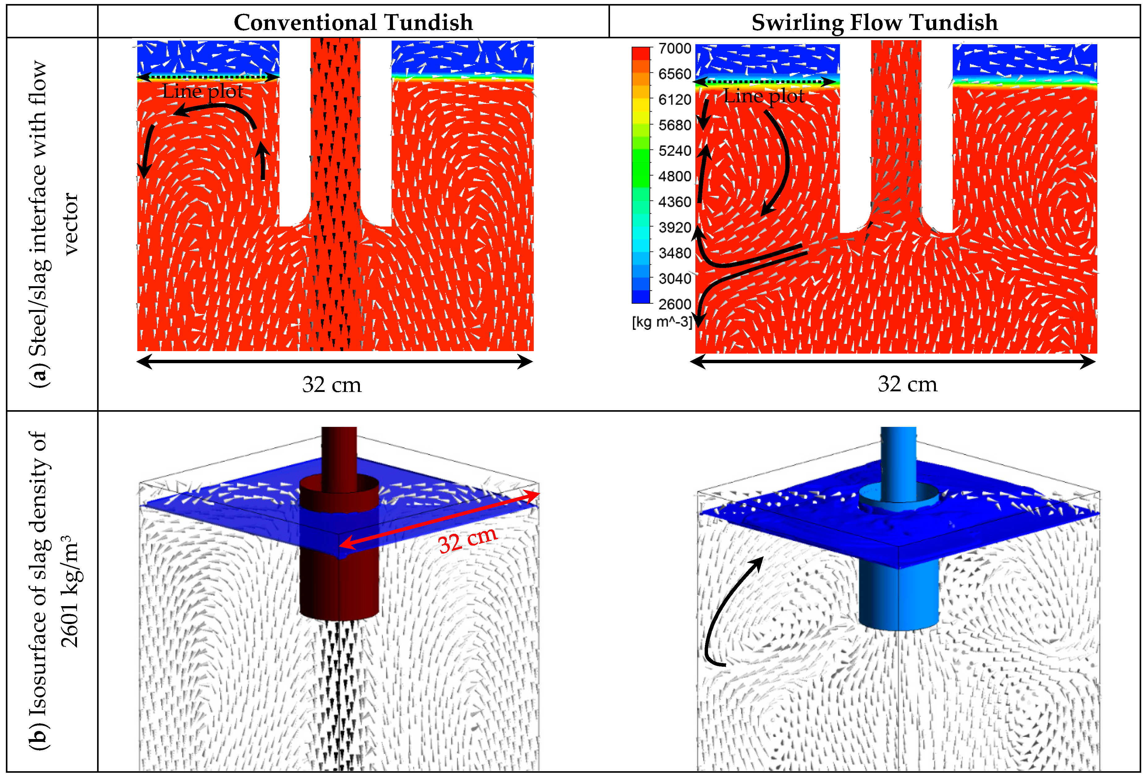
Steel/slag interface phenomena in the mold are very important during the continuous casting process. The reason is that the slag entrainment into the steel may lead to the formation of non-metallic inclusions. Therefore, a large steel/slag interface fluctuation is unwanted in the continuous casting process. Figure 9 shows the steel/slag interface and the flow pattern in the steel and slag. It can be seen that the thickness of the steel/slag interface region is larger when a swirling flow tundish was used, compared a conventional tundish. This can easily be seen from Figure 9b where the isosurface of the slag with the density of 2601 kg/m3 was plotted (the pure slag has the density of 2600 kg/m3). When a conventional tundish SEN was used, steel with a large momentum moves deeply into the mold, and a calm steel flow region at the top part of the mold was obtained. This can be seen from Figure 3a. However, the steel flow is activated in the top of the mold when the swirling flow tundish was used. This leads to a large level fluctuation, while it helps the heat transfer near the meniscus. In the mold with a swirling flow tundish casting, as shown in Figure 9, the steel flowing towards the solidified shell divided into an upwards and a downwards flow. The upwards flow shown in Figure 9b directly moves towards the steel/slag interface with the velocity of around 0.2 m/s, as shown in Figure 3b. Due to the small immersion depth of the SEN in steel with the value of around 12 cm, this velocity is still high when it reaches the steel/slag interface. This should cause a large steel/slag interface fluctuation. However, a flat interface is generally observed in this study. In the case with M-EMS, the level fluctuation was also found to be increased [10,33,64]. The meniscus surface has a swirl flow and the meniscus level rises near the bloom strand wall and sinks around the SEN wall, which shows an inclined steel/slag interface [33]. Sometimes, a vortex formation near the SEN wall was found with M-EMS [64]. Therefore, the mold level fluctuation should be considered to make it as low as possible, both for M-EMS applications and for the use of swirling flow SEN.
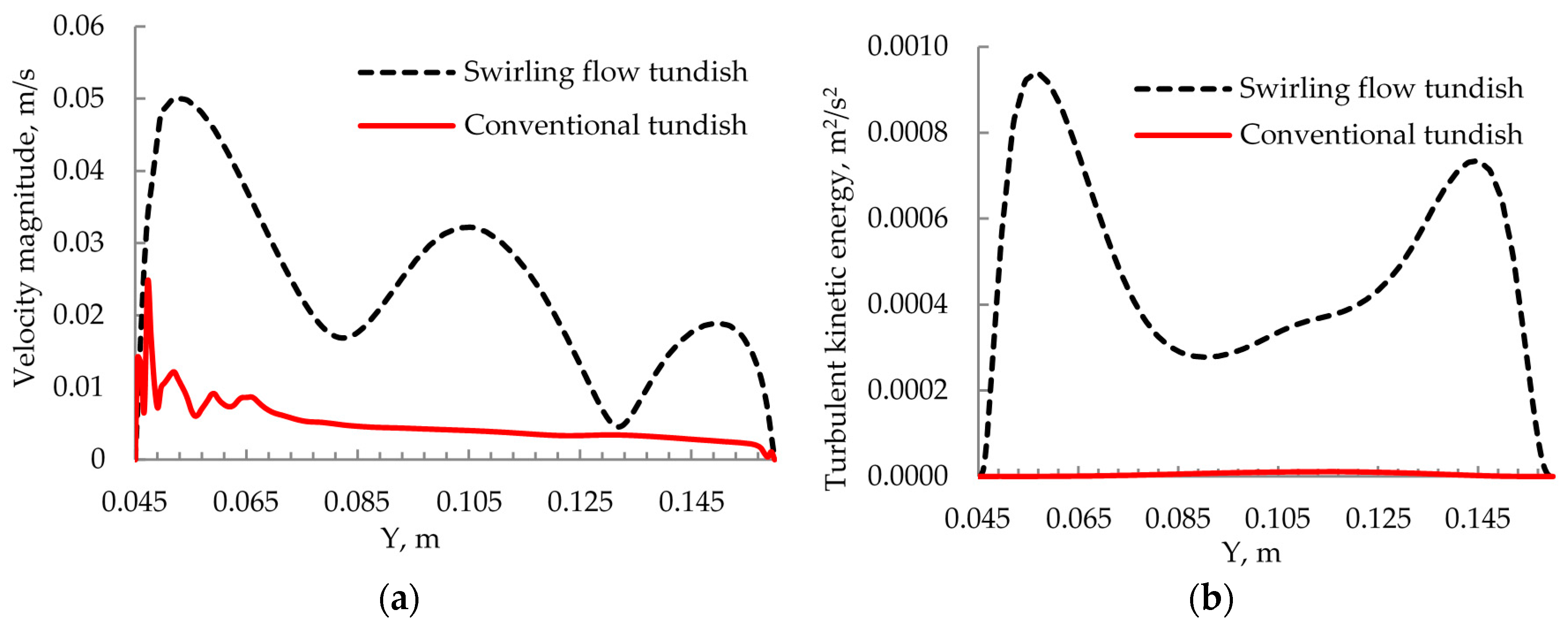
Figure 10 shows the distributions of the velocity magnitude and turbulent kinetic energy along the steel/slag interface. The location of the line plot is shown in Figure 9. It can be seen that the velocity magnitude with the swirling flow tundish case is around 3 times that of a conventional tundish, with the maximum value of 0.05 m/s. However, this maximum value is still smaller than that found in a mold with M-EMS application, where the values can reach around 0.2 to 0.3 m/s [33,64]. The turbulent kinetic energy is close to zero with a conventional tundish casting, and the maximum value is around 0.001 m2/s2 for the swirling flow tundish case. This means that the turbulence intensity is slightly increased when the swirling flow tundish design was used.
According to a previous research [65], the slag entrainment into liquid steel may occur when the Weber number is greater than 12.3. The Weber number can be defined as
where ul is the radial steel velocity, g is gravitational acceleration, and σ is the interfacial tension between steel and slag. A slag density value of 2600 kg/m3 was used, and the value of interfacial tension between the steel and the slag was set to 1.16 N/m [66]. The maximum total velocity at the steel-slag interface in the mold, 0.05 m/s, was used to calculate the Weber number. The calculated maximum Weber number is around 0.8 for the case with the swirling flow tundish casting. Therefore, the Weber number is still much smaller than 12.3, which means a small risk for the slag entrainment. Due to the swirling flow effect, the SEN outlet flow spreads towards the mold wall, rather than goes deep into the mold, as in a conventional tundish casting with a one-port SEN. Therefore, it is possible to increase the immersion depth of the SEN as well, where the value is 15 cm in the current study. This may help to decrease the fluctuations, as well as to further reduce the risk of the slag entrainment. In reality, the slag entrainment issue should be experimentally investigated in the future when a slag is used to protect the steel from the air reoxidation.
3.5. Temperature Distribution
Steel temperature in the mold is very important, since it significantly influences the solidification structure, which in turn determines the product quality. One important issue regarding the steel temperature is the removal of the steel superheat in the mold. Furthermore, a uniform steel temperature in the mold is also important, in order to obtain a uniform solidified shell. The influence of the swirling flow tundish casting on the temperature field in the mold was investigated, where the natural convection in the mold was also considered.
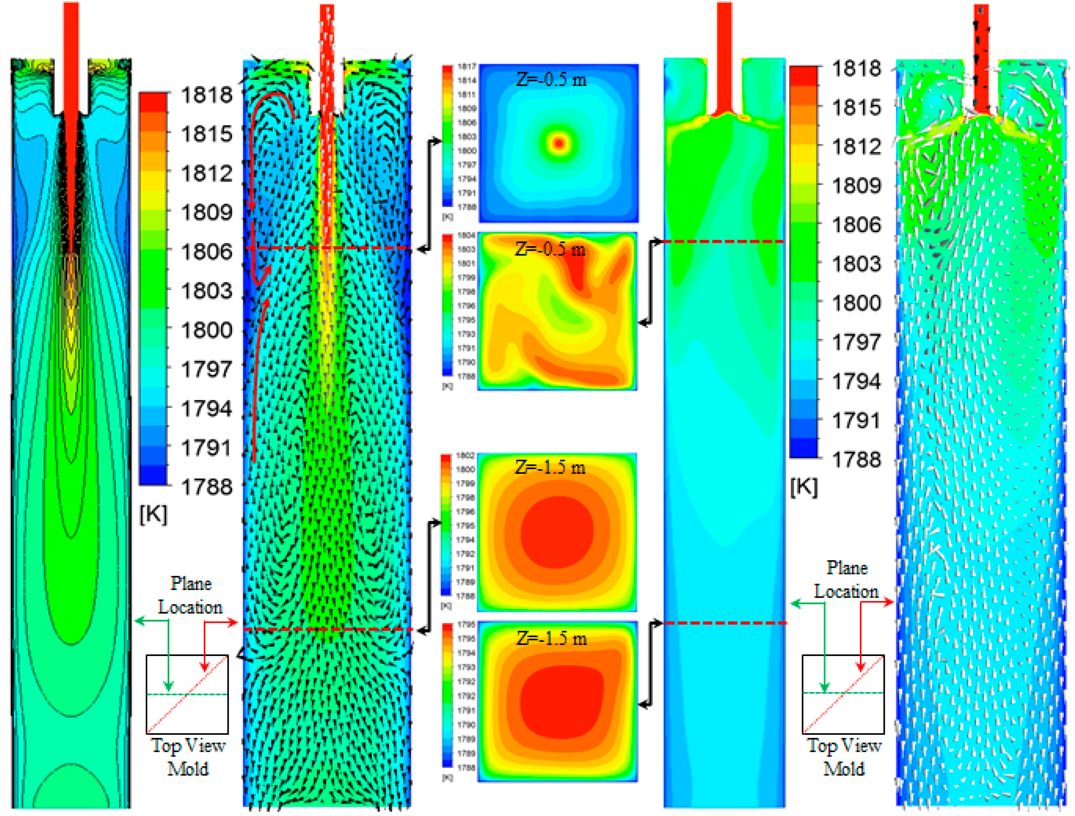
Figure 11 shows the temperature distribution in the mold. It can be seen that the swirling flow tundish design significantly change the temperature distribution in the mold. Specifically, in the mold with a conventional tundish SEN, the steel flow jet with a high temperature directly goes deeply into the mold. This leads to a high temperature region which is located deep in the center of the mold, as shown in Figure 11a. However, the temperature is low in the mold top. Therefore, the temperature field is not uniform in the mold, and it is not good for the removal of the steel superheat. In the top part of the mold, the density of steel in the region near the solidified shell is high, due to the low temperature. Therefore, steel tends to move downwards near the solidified shell. Furthermore, as stated before, the solidified steel shell moves downwards at a speed of 0.013 m/s in order to simulate the movement of the steel shell in a real casting. In addition, the weak rotational flow in the top of the mold also leads to the steel flowing downwards near the solidified shell. These factors lead to a downwards movement of steel with a low temperature as shown in Figure 11a. In the lower part of the mold, the rotational flow leads to an upwards steel flow near the solidified shell. This upwards flow comes from the main flow jet, and thus, has a high temperature. Finally, a low temperature region was formed in the mold at a depth of around 0.5 m, as shown in Figure 11a, where the low temperature downwards flow meets the high temperature upwards flow.
With a swirling flow tundish design, the temperature field in the mold changes a lot, as shown in Figure 11b. The high temperature impingement jet disappears, and the temperature field becomes more uniform in the mold. The maximum temperature gradually decreases, from the mold top to the bottom. Due to the swirling flow effect, steel with a high temperature changes the flow direction towards the solidified shell after it moves out from the SEN outlet. It increases the temperature near the solidified shell, as well as the temperature gradient there. Furthermore, this enhanced the removal of the steel superheat, and the core temperature of the billet was dramatically reduced. On the cross section at a depth of 0.5 m in the mold, the maximum temperature for the conventional tundish case and the swirling flow tundish case is 1817 and 1804 K, respectively. These values decrease to 1802 K for the conventional tundish casting and to 1795 K for the swirling flow tundish casting at the mold depth of 1.5 m. Therefore, the swirling flow improves the steel superheat removal and leads to a more uniform temperature field in the mold. This is good for the quality of the steel solidification structure with the formation of equiaxed grains. A previous study with the application of M-EMS shows that the high temperature region was located at the mold center [32]. This is due to the impingement jet from a straight SEN having a large inertia, and that M-EMS can only reduce the impingement depth, rather than completely remove the impingement jet. This may be the reason that the design of four horizontal side ports, with the port located in the tangential direction of the SEN circumference, was found to further improve the bloom quality cast in a M-EMS mold, compared to that with a straight SEN, due to the improvement in superheat dissipation [8].
3.6. Inclusion Behavior in Mold
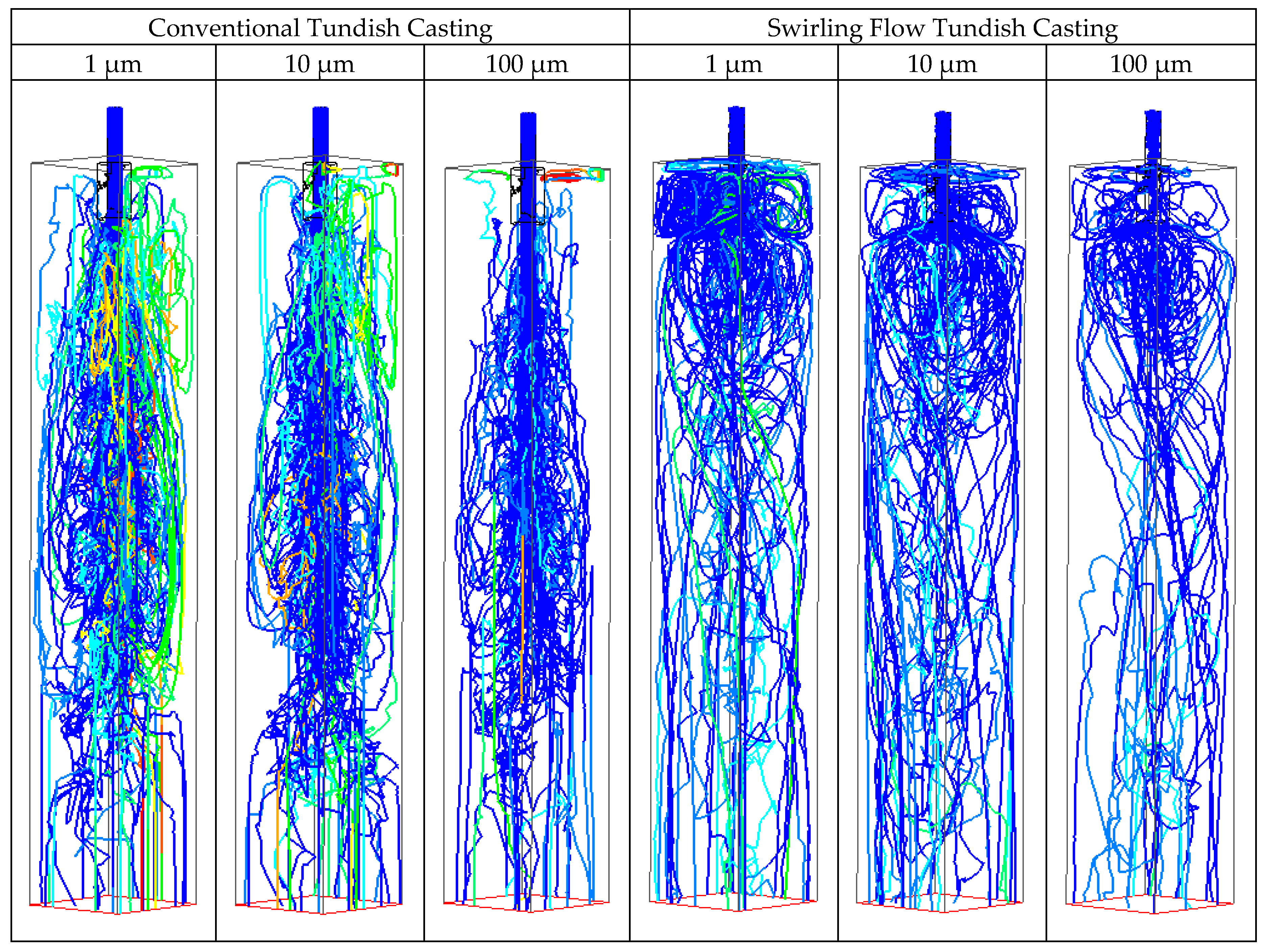
In order to understand the behavior of inclusions, 30 inclusions of 1 µm, 10 µm, and 100 µm, released from the inlet, were individually tracked to see their behaviors in the mold. Figure 12 shows the trajectories of different sizes of inclusions in the mold. It can be seen that the steel flow pattern in the mold has a significant influence on the inclusion motions in the mold. Due to the impingement jet going deep into the mold, inclusions that follow the steel flow can reach a large mold depth in the conventional tundish casting. A few of them stay on the top part of the mold. This is true, even for large inclusions with a diameter of 100 µm, on which a large buoyancy force acts upon compared to small inclusions. Therefore, the steel flow pattern with a conventional tundish SEN is not beneficial for the removal of non-metallic inclusions. In the mold with a swirling flow tundish casting, some inclusions stay on the top of the mold for a time. This is due to the steel flow pattern change as previously shown in Figure 3. This may provide the chances for some inclusions to be removed. However, the buoyancy force is still not large enough to keep the large size inclusions at the top of the mold. In this study, a reflect wall boundary condition was used to show the moving path of inclusions. To realize a dynamic simulation on the inclusion removal into the slag, and the inclusion attachment on the wall, an interface capture model is required, and this is left for a future study.
4. Concluding Discussion
A new cylindrical tundish design that produces a swirling flow in the SEN by using the steel flow potential has been investigated both by water model experiments and numerical simulations [47,48,49,61,67]. This study was the first to try to investigate the influence of such swirling flow tundish design on the steel flow, heat transfer, inclusion motion, and steel/slag interface stability in the mold. Previously, the effect of a swirling flow SEN on the steel flow in molds has been studied [34,38,40,41,42,46]. However, issues such as the steel/slag interface fluctuation, steel velocity in the vicinity of the solidified shell, and the field properties in the deep mold, are still not well investigated. In addition, the density change due to temperature variance was included in the model to consider the natural convection effect on the steel flow. In reality, there is a mushy region near the solidified shell, where the liquid volume fraction and the liquid viscosity change with the distance from the completely solidified shell; this is ignored in this study. Under this assumption, the multiphysics in the mold from a conventional tundish casting, and from the swirling flow tundish casting, are compared to show the influence of the swirling flow tundish design on the mold flow. However, a further study is still required to include the influence of the fluid property changes in the mushy region on the steel flow.
Swirling flow normally shows a certain swirl frequency [67,68], which means that the transient flow characteristics may not be axisymmetric. Therefore, a transient solver is recommended to solve this kind of flow phenomena. In this study, the plotted results are instantaneous flow field properties at 125 s, rather than the averaged flow properties in a time interval which is larger than the characteristic time of the swirling flow. This aims to give a clear observation on the swirling flow characteristics. The flow vectors in Figure 5 show that the flow is not axisymmetric. This is due to that the swirling flow in the SEN is not completely axisymmetric, as shown in Figure 1. However, the flow symmetry can be further improved by the cylindrical tundish design, such as using two tangential inlets in the cylindrical tundish in Figure 1a, which was investigated in a previous study [67]. For the study on M-EMS application, it was also found that the distribution of the electromagnetic force is not uniform in space [33]. The experimental measurements reveal that an axisymmetric flow cannot be maintained for situations with the simultaneous occurrence of the SEN jet flow and an electromagnetic stirring [64]. Therefore, efforts are still required in order to improve the flow uniformity.
The swirling flow intensity in the SEN is influenced by the cylindrical tundish design. Important design factors include the diameter of the cylinder and the steel flow velocity at the tangential inlet of the cylinder, as well as the tundish inlet area [47,49]. With a proper cylindrical tundish parameter, a certain intensity of the swirling flow in the SEN can be obtained. This should be determined by the desired flow behavior in the mold, such as the control of the mold level fluctuation. In addition, the swirling flow tundish casting can be simply realized either by connecting a small cylindrical tundish to a conventional tundish [47,48], or by installing a ceramic cylinder inside a conventional tundish [67]. Therefore, the functions of a conventional tundish, such as the inclusion removal, are not destroyed.
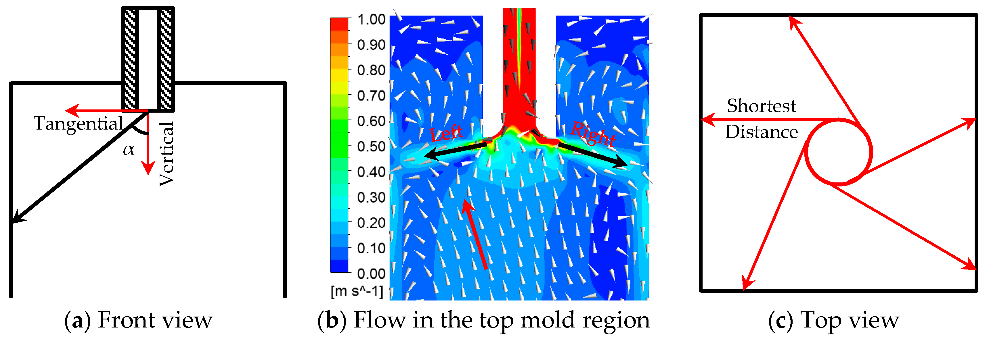
With a swirling flow in SEN, the steel flow has both a tangential momentum and a vertical momentum. These two momentum components influence the spreading angle of the SEN outlet flow. In addition, the steel flow in the mold is also affected by the geometry of the SEN outlet. Previous studies [8,38,40] regarding the swirling flow SEN show that a divergent nozzle can lead to the SEN outlet flow spreading more widely. In the current study, a divergent nozzle was used with only a small expansion in diameter at the SEN outlet, and it seemed to have almost no effect on the mold flow in a conventional tundish casting, where a straight impingement jet flow was observed. However, a wide spreading was observed when it was used together with the swirling flow tundish design. The spreading angle of the steel flow from the SEN is shown to be of great influence on the heat and fluid flow in the mold [38,40]. However, regarding the formation mechanism of the spreading angle, it is not well explained. Previous investigations on divergent nozzles were carried out in a swirling flow, which was produced by installing a swirl blade inside a SEN [38,40]. The mean value of tangential velocity in the SEN is around 1.72 m/s, and the averaged axial velocity is 2 m/s. A significant influence of the divergent nozzle angle on the steel flow spreading was found. However, a large spreading of the steel flow, as that shown in Figure 3b, was also found by Ying et al. [46], with a straight nozzle used in their study, where the swirling flow was produced by installing an electromagnetic stirrer surrounding the SEN. Furthermore, the spreading angle of the steel flow was found to change with the power input, which relates to the swirling flow intensity. This means that the divergent nozzle is not the necessary factor for the steel flow spreading. Figure 13 shows the SEN outlet flow direction in the mold. Theoretically, the spreading angle of the steel flow should be determined by the ratio of the tangential velocity to the axial velocity at the moment that steel leaves the SEN. This ratio in the current study is around 1.47, which corresponds to the spreading angle α of around 56° in Figure 13a. Figure 13b shows that the spreading angle is larger than this value. This is due to the induced upwards flow by the swirling flow tundish SEN in the mold center, which shifts the SEN outlet flow upwards. Since the instantaneous flow is not axisymmetric, the left side upwards flow is stronger than that on the right side. This may create a larger spreading angle on the left side than that on the right side. In addition, the steel tends to flow along the inner wall of the divergent nozzle, due to its inertia. Therefore, the swirling flow will undergo an expansion inside a divergent nozzle, due to the expanding nozzle diameter. This expansion further reduces the pressure in the swirling flow center and increases the low-pressure area. Therefore, steel near the divergent nozzle outlet will flow into the swirling flow center, creating an upwards steel flow. This may increase the shift of the steel flow angle compared to a straight nozzle, which has been observed in a previous study [38,40]. Finally, the swirling flow leads to a horizontal movement of the steel. The shortest distance for the steel reaching the solidified shell is shown in Figure 13c. During the way to the solidified shell, the velocity of the steel flow will decrease due to the momentum dissipation. Therefore, the magnitude of the steel flow velocity near the solidified shell should be greatly influenced by this distance. This distance in the current study is different, as shown in Figure 13c. This is also the reason that a non-uniform wall shear stress in Figure 7b was observed. Furthermore, the uniformity of shear stresses is expected to be improved in a round billet mold, since the distance from the SEN to the solidified shell will be equal in all directions. In addition, the velocity magnitude near the solidified shell might be increased by using a SEN with a large gradual expansion in diameter. With this kind of SEN, the swirling flow will have a gradually expanding and developing process, instead of a sudden expansion from a small SEN diameter to the large mold cross section. This may be helpful for the optimization of the mold flow, and it is left for a future study.
5. Conclusions
Multiphase flow and heat transfer in a mold with a new cylindrical tundish design during the continuous casting process were investigated by using numerical simulations. Steel and slag flow, heat transfer, and inclusion motion in the mold were analyzed. The main conclusions were the following:
- The new cylindrical tundish design for swirling flow casting significantly changed the flow behavior in the mold. The deep impingement jet in the mold disappeared, and the steel flow moved towards the solidified shell, due to the swirling flow effect. A large velocity in the vicinity of the solidified shell was obtained.
- The steel flow velocity in the top part of the mold was increased. The calculated Weber number was round 0.8, which indicates a small risk for the slag entrainment.
- With the swirling flow tundish casting, the temperature distribution became more uniform, and the dissipation of the steel superheat was accelerated. Furthermore, due to the high temperature steel directly flowing to the solidified shell, the temperature near the solidified shell was increased. A high temperature region was found at the top part of the mold, rather than in the deep center of the mold in a conventional tundish casting.
- Inclusion trajectories in the mold change a lot, due to the change of the SEN outlet flow pattern. Instead of moving deeply into the mold following the impingement jet, some inclusions tended to stay for a time at the top part of the mold. This may be helpful for their removal.
Author Contributions
P.N. and L.T.I.J. designed the paper; P.N. and M.E. did the numerical simulation; all the authors analyzed and discussed the results; P.N. wrote the paper; M.E., L.T.I.J., T.Z. and P.G.J. revised the paper.
Funding
National Natural Science Foundation of China (Grant No. 51704062).
Acknowledgments
The authors want to thank the National Natural Science Foundation of China (Grant No. 51704062) for the support on this work.
Conflicts of Interest
The authors declare no conflict of interest.
References
- Szekely, J.; Yadoya, R.T. The physical and mathematical modelling of the flow field in the mold region of continuous casting systems. Part II. The mathematical representation of the turbulence flow field. Metall. Mater. Trans. 1973, 4, 1379–1388. [Google Scholar] [CrossRef]
- Xu, M.; Zhu, M. Transport phenomena in a Beam-Blank continuous casting mold with two types of submerged entry nozzle. ISIJ Int. 2015, 55, 791–798. [Google Scholar] [CrossRef]
- Thomas, B.G.; Mika, L.J.; Najjar, F.M. Simulation of fluid flow inside a continuous slab-casting machine. Metall. Mater. Trans. B 1990, 21, 387–400. [Google Scholar] [CrossRef]
- Calderon-Ramos, I.; Morales, R.D.; Garcia-Hernandez, S.; Ceballos-Huerta, A. Effects of immersion depth on flow turbulence of liquid steel in a slab mold using a nozzle with upward angle rectangular ports. ISIJ Int. 2014, 54, 1797–1806. [Google Scholar] [CrossRef]
- Calderon-Ramos, I.; Morales, R.D.; Salazar-Campoy, M. Modeling flow turbulence in a continuous casting slab mold comparing the use of two bifurcated nozzles with square and circular ports. Steel Res. Int. 2015, 86, 1610–1621. [Google Scholar] [CrossRef]
- Calderon-Ramos, I.; Morales, R.D. The role of submerged entry nozzle port shape on fluid flow turbulence in a slab mold. Metall. Mater. Trans. B 2015, 46, 1314–1325. [Google Scholar] [CrossRef]
- Salazar-Campoy, M.; Morales, R.D.; Najera-Bastida, A.; Cedillo-Hernandez, V.; Delgado-Pureco, J.C. A physical model to study the effects of nozzle design on dense two-phase flows in a slab mold casting Ultra-Low carbon steels. Metall. Mater. Trans. B 2017, 48, 1376–1389. [Google Scholar] [CrossRef]
- Sun, H.; Zhang, J. Macrosegregation improvement by swirling flow nozzle for bloom continuous castings. Metall. Mater. Trans. B 2014, 45, 936–946. [Google Scholar] [CrossRef]
- Sun, H.; Li, L. Application of swirling flow nozzle and investigation of superheat dissipation casting for bloom continuous casing. Ironmak. Steelmak. 2016, 43, 228–233. [Google Scholar] [CrossRef]
- Fang, Q.; Ni, H.; Zhang, H.; Wang, B.; Lv, Z. The effects of a submerged entry nozzle on flow and initial solidification in a continuous casting bloom mold with electromagnetic stirring. Metals 2017, 7, 146. [Google Scholar] [CrossRef]
- Thomas, B.G.; Dennisov, A.; Bai, H. Behavior of argon bubbles during continuous casting of steel. In Proceedings of the ISS 80th Steelmaking Conference, Chicago, IL, USA, 13–16 April 1997; pp. 375–384. [Google Scholar]
- Thomas, B.G.; Huang, X.; Sussman, R.C. Simulation of argon gas flow effects in a continuous slab caster. Metall. Mater. Trans. B 1994, 25, 527–547. [Google Scholar] [CrossRef]
- Li, B.; Okane, T.; Umeda, T. Modeling of biased flow phenomena associated with the effects of static magnetic-field application and argon gas injection in slab continuous casting of steel. Metall. Mater. Trans. B 2001, 32, 1053–1066. [Google Scholar] [CrossRef]
- Wang, Y.; Zhang, L. Fluid flow-related transport phenomena in steel slab continuous casting strands under electromagnetic brake. Metall. Mater. Trans. B 2011, 42, 1319–1351. [Google Scholar] [CrossRef]
- Liu, Z.; Li, B.; Jiang, M. Transient asymmetric flow and bubble transport inside a slab continuous casting mold. Metall. Mater. Trans. B 2014, 45, 675–697. [Google Scholar] [CrossRef]
- Liu, Z.; Li, L.; Qi, F.; Li, B.; Jiang, M.; Tsukihashi, F. Population balance modeling of polydispersed bubbly flow in continuous casting using multiple-size-group approach. Metall. Mater. Trans. B 2015, 46, 406–420. [Google Scholar] [CrossRef]
- Liu, Z.; Sun, Z.; Li, B. Modeling of quasi-four-phase flow in continuous casting mold using hybrid Eulerian and Lagrangian approach. Metall. Mater. Trans. B 2017, 48, 1248–1267. [Google Scholar] [CrossRef]
- Liu, Z.; Li, B. Large-Eddy simulation of transient horizontal gas–liquid flow in continuous casting using dynamic subgrid-scale model. Metall. Mater. Trans. B 2017, 48, 1833–1849. [Google Scholar] [CrossRef]
- Pfeiler, C.; Wu, M.; Ludwig, A. Influence of argon gas bubbles and non-metallic inclusions on the flow behavior in steel continuous casting. Mater. Sci. Eng. A 2005, 413–414, 115–120. [Google Scholar] [CrossRef]
- Yu, H.; Zhu, M. Numerical simulation of the effects of electromagnetic brake and argon gas injection on the three-dimensional multiphase flow and heat transfer in slab continuous casting mold. ISIJ Int. 2008, 48, 584–591. [Google Scholar] [CrossRef]
- Cho, S.; Kim, S.; Thomas, B.G. Transient fluid flow during steady continuous casting of steel slabs: Part I. measurements and modeling of two-phase flow. ISIJ Int. 2014, 54, 845–854. [Google Scholar] [CrossRef]
- Jin, K.; Thomas, B.G.; Ruan, X. Modeling and measurements of multiphase flow and bubble entrapment in steel continuous casting. Metall. Mater. Trans. B 2016, 47, 548–565. [Google Scholar] [CrossRef]
- Cho, S.; Thomas, B.G.; Kim, S. Transient two-phase flow in slide-gate nozzle and mold of continuous steel slab casting with and without double-ruler electro-magnetic braking. Metall. Mater. Trans. B 2016, 47, 3080–3098. [Google Scholar] [CrossRef]
- Cukierski, K.; Thomas, B.G. Flow control with local electromagnetic braking in continuous casting of steel slabs. Metall. Mater. Trans. B 2008, 39, 94–107. [Google Scholar] [CrossRef]
- Zhang, L.; Wang, Y.; Zuo, X. Flow transport and inclusion motion in steel continuous-casting mold under submerged entry nozzle clogging condition. Metall. Mater. Trans. B 2008, 39, 534–550. [Google Scholar] [CrossRef]
- Gonzalez-Trejo, J.; Real-Ramirez, C.A.; Miranda-Tello, R.; Rivera-Perez, F.; Cervantes-De-La-Torre, F. Numerical and physical parametric analysis of a SEN with flow conditioners in slag continuous casting mold. Arch. Metall. Mater. 2017, 62, 927–946. [Google Scholar] [CrossRef]
- Miao, X.; Timmel, K.; Lucas, D.; Ren, Z.; Eckert, S.; Gerbeth, G. Effect of an electromagnetic brake on the turbulent melt flow in a continuous-casting mold. Metall. Mater. Trans. B 2012, 43, 954–972. [Google Scholar] [CrossRef]
- Liu, Z.; Li, L.; Li, B. Large eddy simulation of transient flow and inclusions transport in continuous casting mold under different electromagnetic brakes. JOM 2016, 68, 2180–2190. [Google Scholar] [CrossRef]
- Ha, M.Y.; Lee, H.G.; Seong, S.H. Numerical simulation of three-dimensional flow, heat transfer, and solidification of steel in continuous casting mold with electromagnetic brake. J. Mater. Process. Technol. 2003, 133, 322–339. [Google Scholar] [CrossRef]
- Yu, H.; Wang, B.; Li, H.; Li, J. Influence of electromagnetic brake on flow field of liquid steel in the slab continuous casting mold. J. Mater. Process. Technol. 2008, 202, 179–187. [Google Scholar]
- Yu, H.; Zhu, M. Three-dimensional magnetohydrodynamic calculation for coupling multiphase flow in round billet continuous casting mold with electromagnetic stirring. IEEE Trans. Magn. 2010, 46, 82–86. [Google Scholar]
- Yu, H.; Zhu, M. Influence of electromagnetic stirring on transport phenomena in round billet continuous casting mould and macrostructure of high carbon steel billet. Ironmak. Steelmak. 2012, 39, 574–584. [Google Scholar] [CrossRef]
- Liu, H.; Xu, M.; Qiu, S.; Zhang, H. Numerical simulation of fluid flow in a round bloom mold with In-Mold rotary electromagnetic stirring. Metall. Mater. Trans. B 2012, 43, 1657–1675. [Google Scholar] [CrossRef]
- Yokoya, S.; Takagi, S.; Iguchi, M.; Asako, Y.; Westoff, R.; Hara, S. Swirling effect in immersion nozzle on flow and heat transport in billet continuous casting mold. ISIJ Int. 1998, 38, 827–833. [Google Scholar] [CrossRef]
- Yokoya, S.; Takagi, S.; Iguchi, M.; Marukawa, K.; Yasugair, W.; Hara, S. Development of swirling flow generator in immersion nozzle. ISIJ Int. 2000, 40, 584–588. [Google Scholar] [CrossRef]
- Yokoya, S.; Takagi, S.; Kaneko, M.; Iguchi, M.; Marukawa, K.; Hara, S. Swirling flow effect in off-center immersion nozzle on bulk flow in billet continuous casting mold. ISIJ Int. 2001, 41, 1215–1220. [Google Scholar] [CrossRef]
- Yokoya, S.; Takagi, S.; Ootani, S.; Iguchi, M.; Marukawa, K.; Hara, S. Swirling flow effect in submerged entry nozzle on bulk flow in high throughput slab continuous casting mold. ISIJ Int. 2001, 41, 1208–1214. [Google Scholar] [CrossRef]
- Yokoya, S.; Jönsson, P.G.; Sasaki, K.; Tada, K.; Takagi, S.; Iguchi, M. The effect of swirl flow in an immersion nozzle on the heat and fluid flow in a billet continuous casting mold. Scan. J. Metall. 2004, 33, 22–28. [Google Scholar] [CrossRef]
- Tsukaguchi, Y.; Hayashi, H.; Kurimoto, H.; Yokoya, S.; Marukawa, K.; Tanaka, T. Development of swirling-flow submerged entry nozzles for slab casting. ISIJ Int. 2010, 50, 721–729. [Google Scholar] [CrossRef]
- Kholmatov, S.; Takagi, S.; Jonsson, L.; Jönsson, P.; Yokoya, S. Development of flow field and temperature distribution during changing divergent angle of the nozzle when using swirl flow in a square continuous casting billet mould. ISIJ Int. 2007, 47, 80–87. [Google Scholar] [CrossRef]
- Kholmatov, S.; Takagi, S.; Jönsson, P.; Jonsson, L.; Yokoya, S. Influence of aspect ratio on fluid flow and heat transfer in mould when using swirl flow during casting. Steel Res. Int. 2008, 79, 698–707. [Google Scholar] [CrossRef]
- Kholmatov, S.; Takagi, S.; Jonsson, L.; Jönsson, P.; Yokoya, S. Effect of nozzle angle on flow field and temperature distribution in a billet mould when using swirl flow. Steel Res. Int. 2008, 79, 31–39. [Google Scholar] [CrossRef]
- Geng, D.; Lei, H.; He, J.; Liu, H. Effect of electromagnetic swirling flow in slide-gate SEN on flow field in square billet continuous casting mold. Acta Metall. Sin. (Engl. Lett.) 2012, 25, 347–356. [Google Scholar]
- Wondrak, Th.; Eckert, S.; Galindo, V.; Gerbeth, G.; Stefani, F.; Timmel, K.; Peyton, A.J.; Yin, W.; Riaz, S. Liquid metal experiments with swirling flow submerged entry nozzle. Ironmak. Steelmak. 2012, 39, 1–9. [Google Scholar] [CrossRef]
- Li, D.; Su, Z.; Chen, J.; Wang, Q.; Yang, Y.; Nakajima, K.; Marukaw, K.; He, J. Effects of electromagnetic swirling flow in submerged entry nozzle on square billet continuous casting of steel process. ISIJ Int. 2013, 53, 1187–1194. [Google Scholar] [CrossRef]
- Yang, Y.; Jönsson, P.G.; Ersson, M.; Su, Z.; He, J.; Nakajima, K. The Influence of swirl flow on the flow field, temperature field and inclusion behavior when using a half type electromagnetic swirl flow generator in a submerged entry and mold. Steel Res. Int. 2015, 86, 1312–1327. [Google Scholar] [CrossRef]
- Ni, P.; Jonsson, L.; Ersson, M.; Jönsson, P. A new tundish design to produce a swirling flow in the SEN during continuous casting of steel. Steel Res. Int. 2016, 87, 1356–1365. [Google Scholar] [CrossRef]
- Ni, P.; Jonsson, L.; Ersson, M.; Jönsson, P. Non-Metallic inclusion behaviors in a new tundish and SEN design using a swirling flow during continuous casting of steel. Steel Res. Int. 2017, 88, 1600155. [Google Scholar] [CrossRef]
- Ni, P.; Wang, D.; Jonsson, L.; Ersson, M.; Zhang, T.; Jönsson, P. Numerical and physical study on a cylindrical tundish design to produce a swirling flow in the SEN during continuous casting of steel. Metall. Mater. Trans. B 2017, 48, 2695–2706. [Google Scholar] [CrossRef]
- Wang, S.; Yang, V.; Hsiao, G.; Hsieh, S.; Mongia, H.C. Large-eddy simulation of gas-turbine swirl injector flow dynamics. J. Fluid Mech. 2007, 583, 99–122. [Google Scholar] [CrossRef]
- Weber, R.; Visser, B.M.; Boysan, F. Assessment of turbulence modeling for engineering predictions of swirling vortices in the near burner zone. Int. J. Heat Fluid Flow 1990, 11, 225–235. [Google Scholar] [CrossRef]
- Hoekstra, A.; Derksen, J.; Van Den Akker, H. An experimental and numerical study on turbulent swirling flow in gas cyclones. Chem. Eng. Sci. 1999, 54, 2055–2065. [Google Scholar] [CrossRef]
- Jakirlic, S.; Hanjalic, K.; Tropea, C. Modeling rotating and swirling turbulent flows: A perpetual challenge. AIAA J. 2002, 40, 1984–1996. [Google Scholar] [CrossRef]
- Patankar, S.V. Numerical Heat Transfer and Fluid Flow; Hemispere Publishing Corp.: New York, NY, USA, 1980. [Google Scholar]
- ANSYS. Fluent Theory Guide; Release 18.0; ANSYS: Canonsburg, PA, USA, 2017. [Google Scholar]
- Versteeg, H.K.; Malalasekera, W. An Introduction to Computational Fluid Dynamics: The Finite Volume Method, 2nd ed.; Pearson Education Limited: London, UK, 2007; p. 80. [Google Scholar]
- Launder, B.E.; Reece, G.J.; Rodi, W. Progress in the development of a Reynolds-stress turbulence closure. J. Fluid Mech. 1975, 68, 537–566. [Google Scholar] [CrossRef]
- Lien, F.S.; Leschziner, M.A. Assessment of turbulence-transport models including non-linear RNG eddy-viscosity formulation and second-moment closure for flow over a backward-facing step. Comput. Fluids 1994, 23, 983–1004. [Google Scholar] [CrossRef]
- Shih, T.-H.; Liou, W.W.; Shabbir, A.; Yang, Z.; Zhu, J. A new k-ε eddy viscosity model for high Reynolds number turbulent flows. Comput. Fluids 1995, 24, 227–238. [Google Scholar] [CrossRef]
- ANSYS. Fluent User’s Guide; Release 18.0; ANSYS: Canonsburg, PA, USA, 2017. [Google Scholar]
- Ni, P.; Ersson, M.; Jonsson, L.; Jönsson, P. A study on the nonmetallic inclusion motions in a swirling flow submerged entry nozzle in a new cylindrical Tundish design. Metall. Mater. Trans. B 2018, 49, 723–736. [Google Scholar] [CrossRef]
- Saffman, P.G. The lift on a small sphere in a slow shear flow. J. Fluid Mech. 1965, 22, 385–400. [Google Scholar] [CrossRef]
- Morsi, S.A.; Alexander, A.J. An investigation of particle trajectories in two-phase flow systems. J. Fluid Mech. 1972, 55, 193–208. [Google Scholar] [CrossRef]
- Willers, B.; Barna, M.; Reiter, J.; Eckert, S. Experimental investigations of rotary electromagnetic mould stirring in continuous casting using a cold liquid metal model. ISIJ Int. 2017, 57, 468–477. [Google Scholar] [CrossRef]
- Jonsson, L.; Jönsson, P. Modeling of fluid flow conditions around the slag/metal interface in a gas-stirred ladle. ISIJ Int. 1996, 36, 1127–1134. [Google Scholar] [CrossRef]
- Shannon, G.N.; Sridhar, S. Film-drainage, separation and dissolution of Al2O3 inclusions at steel/interfaces. High Temp. Mater. Process. 2005, 24, 111–124. [Google Scholar] [CrossRef]
- Ni, P.; Ersson, M.; Jonsson, L.; Jönsson, P.G. Application of a swirling flow producer in a conventional tundish during continuous casting of steel. ISIJ Int. 2017, 57, 2175–2184. [Google Scholar] [CrossRef]
- Bai, H.; Ersson, M.; Jönsson, P. Experimental validation and numerical analysis of the swirling flow in a submerged entry nozzle and mold by using a reverse turboswirl in a billet continuous casting process. Steel Res. Int. 2017, 88, 1600399. [Google Scholar] [CrossRef]
Figure 1.
(a) Location of the cross section used as the inlet boundary condition of the mold simulation and the tangential velocity distribution on it, (b) velocity distribution along the line on the cross section (negative values for vertical velocity means in gravity direction), and (c) calculation domain in mold.

Figure 2.
Comparison of steel flow paths in mold. (a) Casting with a conventional tundish and (b) casting with a swirling flow tundish.
Figure 2.
Comparison of steel flow paths in mold. (a) Casting with a conventional tundish and (b) casting with a swirling flow tundish.

Figure 3.
Steel flow velocity in the vertical middle plane of the mold. (a) Conventional tundish casting and (b) Swirling flow tundish design casting (arrows are the steel flow directions).
Figure 3.
Steel flow velocity in the vertical middle plane of the mold. (a) Conventional tundish casting and (b) Swirling flow tundish design casting (arrows are the steel flow directions).
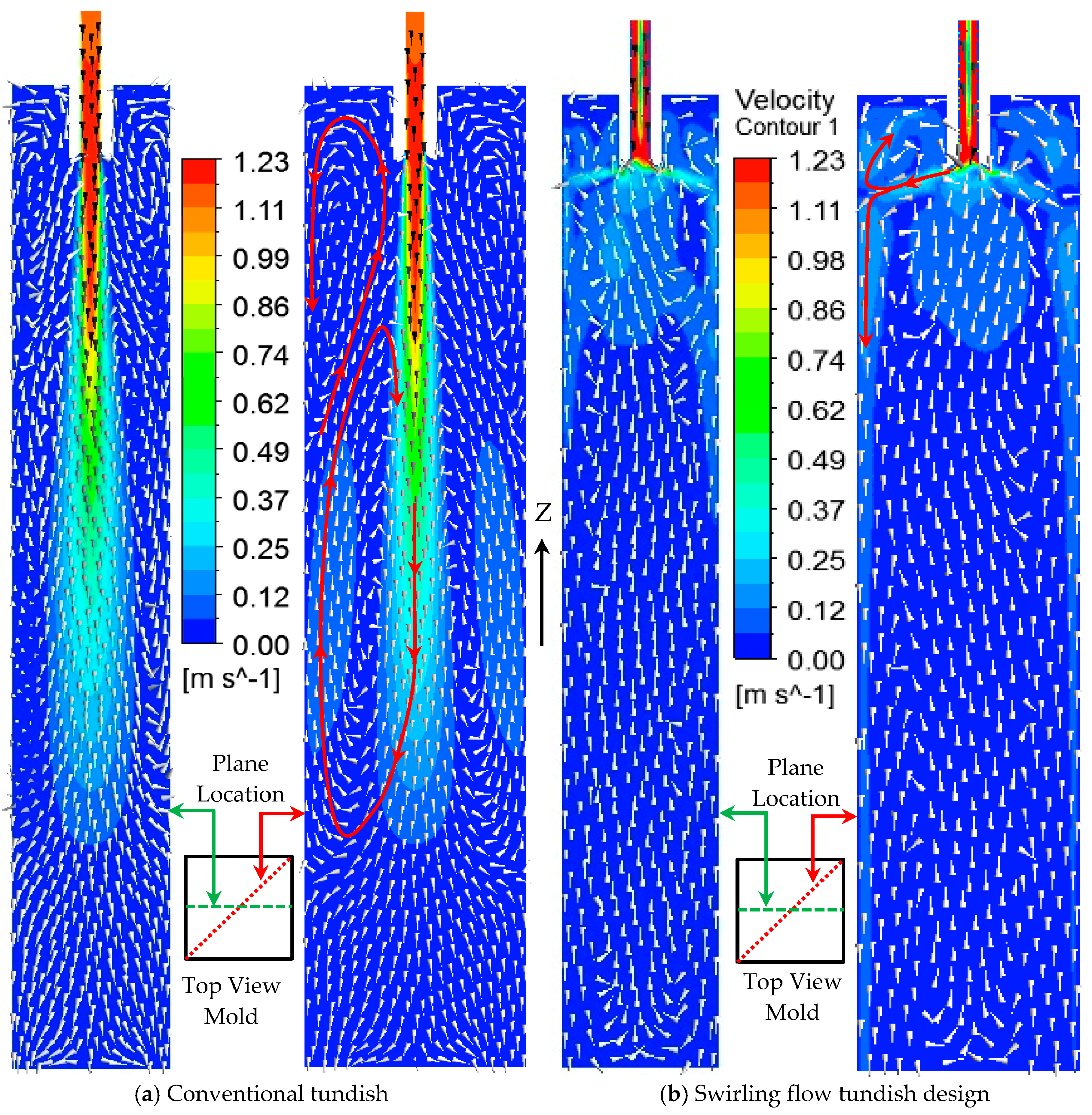
Figure 4.
Vertical steel flow velocity along horizontal lines in different mold depths.

Figure 5.
Tangential velocities on different cross sections of the mold. (a) Conventional tundish casting and (b) swirling flow tundish casting.
Figure 5.
Tangential velocities on different cross sections of the mold. (a) Conventional tundish casting and (b) swirling flow tundish casting.

Figure 6.
Tangential velocity distribution along different horizontal lines in different mold depths.
Figure 6.
Tangential velocity distribution along different horizontal lines in different mold depths.

Figure 7.
Shear stress on the solidified shell. (a) Conventional tundish casting and (b) swirling flow tundish casting.
Figure 7.
Shear stress on the solidified shell. (a) Conventional tundish casting and (b) swirling flow tundish casting.

Figure 8.
Turbulence properties on the YZ middle plane of the mold.

Figure 9.
Steel/slag interface with steel flow vectors.

Figure 10.
(a) Velocity magnitude at the steel/slag interface and (b) turbulent kinetic energy at the steel/slag interface.
Figure 10.
(a) Velocity magnitude at the steel/slag interface and (b) turbulent kinetic energy at the steel/slag interface.

Figure 11.
Temperature distribution in mold. (a) Conventional tundish casting and (b) swirling flow tundish design casting.
Figure 11.
Temperature distribution in mold. (a) Conventional tundish casting and (b) swirling flow tundish design casting.

Figure 12.
Trajectories of different size inclusions in the mold.

Figure 13.
Steel flow direction and its collision location with solidified shell. (a) Front view schematic, (b) flow in the top mold region, and (c) top view schematic.
Figure 13.
Steel flow direction and its collision location with solidified shell. (a) Front view schematic, (b) flow in the top mold region, and (c) top view schematic.

Table 1.
Thermal properties of the steel and slag.
| Parameters | Symbols | Steel | Slag |
|---|---|---|---|
| Density, kg/m3 | ρo | 7000 | 2600 |
| Viscosity, kg/(m·s) | µ | 0.0064 | 0.09 |
| Thermal conductivity, W/(m·K) | k | 35 | 1.1 |
| Specific heat, J/(kg·K) | cp | 628 | 1200 |
| Thermal expansion coefficient, 1/K | β | 10−4 | - |
| Interfacial tension, N/m | σ | 1.6 | |
| Operating temperature, K | To | 1788 | |
| Turbulent Prandtl number | Prt | 0.85 | |
© 2018 by the authors. Licensee MDPI, Basel, Switzerland. This article is an open access article distributed under the terms and conditions of the Creative Commons Attribution (CC BY) license (http://creativecommons.org/licenses/by/4.0/).
Share and Cite
MDPI and ACS Style
Ni, P.; Ersson, M.; Jonsson, L.T.I.; Zhang, T.-a.; JÖNSSON, P.G. Numerical Study on the Influence of a Swirling Flow Tundish on Multiphase Flow and Heat Transfer in Mold. Metals 2018, 8, 368. https://doi.org/10.3390/met8050368
AMA Style
Ni P, Ersson M, Jonsson LTI, Zhang T-a, JÖNSSON PG. Numerical Study on the Influence of a Swirling Flow Tundish on Multiphase Flow and Heat Transfer in Mold. Metals. 2018; 8(5):368. https://doi.org/10.3390/met8050368
Chicago/Turabian StyleNi, Peiyuan, Mikael Ersson, Lage Tord Ingemar Jonsson, Ting-an Zhang, and Pär Göran JÖNSSON. 2018. "Numerical Study on the Influence of a Swirling Flow Tundish on Multiphase Flow and Heat Transfer in Mold" Metals 8, no. 5: 368. https://doi.org/10.3390/met8050368
Note that from the first issue of 2016, this journal uses article numbers instead of page numbers. See further details here.