Effects of Vanadium on Microstructure and Wear Resistance of High Chromium Cast Iron Hardfacing Layer by Electroslag Surfacing

State Key Laboratory of Materials Processing and Die & Mould Technology, Huazhong University of Science and Technology, Wuhan 430074, China
*
Author to whom correspondence should be addressed.
Metals 2018, 8(6), 458; https://doi.org/10.3390/met8060458
Submission received: 18 May 2018
/
Revised: 8 June 2018
/
Accepted: 11 June 2018
/
Published: 15 June 2018
Abstract
:The 3.6C-20Cr-Fe-(0–2.32)V high chromium cast iron (HCCI) hardfacing layers were deposited on low alloy steel by electroslag surfacing. The microstructure of hardfacing layers were observed and the carbide types, size and area fraction were measured. In addition, the hardness and wear resistance were tested. Results show that the interface between hardfacing layer and low alloy steel is defect free. 3.6C-20Cr-Fe hardfacing layer contains primary carbides and eutectic. Increasing V wt % in the hardfacing layer, primary carbides are decreasing by increasing eutectic along with martensite formation. For 1.50 wt % of V, the microstructure contains a lot of eutectic and a little of martensite. For 2.32 wt % of V, primary austenite formed, the microstructure is primary austenite, eutectic and a little of martensite. In the V alloyed hardfacing layers, V has strong affinity with carbon than chromium, hence V can replace a part of Cr in M7C3 and (Cr4.4–4.7Fe2.1–2.3V0.2–0.5)C3 type carbides are formed. When the V is 2.32 wt %, (Cr0.23V0.77)C carbides are formed in the hardfacing layer. The hardness and wear resistance are improved by increasing V from 0 to 1.50 wt %. However, when the V is 2.32 wt %, the primary austenite has reduced the hardness and wear resistance of hardfacing layer.
1. Introduction
Being an important class of wear resistant material, high chromium cast iron (HCCI) can be used for surfacing low alloy steel to form bimetallic material. This bimetallic material overcomes the poor toughness of HCCI and has been used more and more in metallurgy, machinery, mining and other fields [1,2,3]. Whereas the traditional method of surfacing is arc welding that holds techniques of open arc welding and submerged arc welding, etc. Because of the high carbon equivalent of HCCI, it is very easy to form cracks during surfacing process. Although the cracks can release the stress and avoid the spalling of hardfacing layer during the wear process, whereas in many applications, HCCI hardfacing layer is required to have good structural integrity and certain corrosion resistance. Thereby, cracks cannot be allowed in the hardfacing layer [4]. There is a need for a new surfacing method that can reduce the thermal stress during the surfacing process and avoid cracks in the HCCI hardfacing layer. The latest research [5] reveals that in electroslag welding due to high heat input, temperature gets evenly distributed in the workpiece, which reduces the cooling rate, residual stresses and cracking tendency in the hardfacing layer.
The content and size of carbides in HCCI hardfacing layer has significant impact on its wear resistance [6,7,8]. Normally, HCCI with high carbon content contains a large amount of carbides, but a considerable part of them are large-size primary carbides. These coarse primary carbides are easy to be fractured and spalled during the wear process with heavy impact [9,10]. So the refinement of primary carbides and increasing of eutectic carbides content are of significant importance to improve the wear resistance of HCCI hardfacing layer.
The volume fraction and size of M7C3 carbides in HCCI can be affected by alloying elements such as Nb, Ti and V [11,12,13]. Additions of Nb and Ti can refine the microstructure of the HCCI alloy but cannot increase the content of eutectic M7C3 carbides [14,15]. Studies [16,17] reveal that V can promote the precipitation of secondary carbides during the solid-state phase transformation. Therefore, it is possible that V-alloyed electroslag HCCI hardfacing layer can obtain good wear resistance without post surfacing heat treatment. Thermodynamic analyses [18] reveal that vanadium partitioning in between matrix and the carbide happens, which increase the abrasive wear resistance effectively. Thereby, vanadium’s twofold effect on both the microstructure and the stereological characteristics of carbides makes it a sensible choice of HCCI hardfacing alloying. Reasonable works [17,19,20,21,22,23] have been done relating the effect of vanadium alloy on HCCI microstructure and property. However, these results are focusing on HCCI in casting process.
In the current study, the 3.6C-20Cr-Fe HCCI hardfacing layers with varying V additive (0–2.32 wt %) were deposited on low alloy steel D32 by electroslag surfacing. Furthermore, the effects of V additive on the microstructure, carbides, the corresponding hardness and wear resistance of electroslag HCCI hardfacing layer were discussed in detail. This work is intended to provide data that will underpin future development of the HCCI electroslag surfacing and will also be useful for the production operations.
2. Materials and Methods
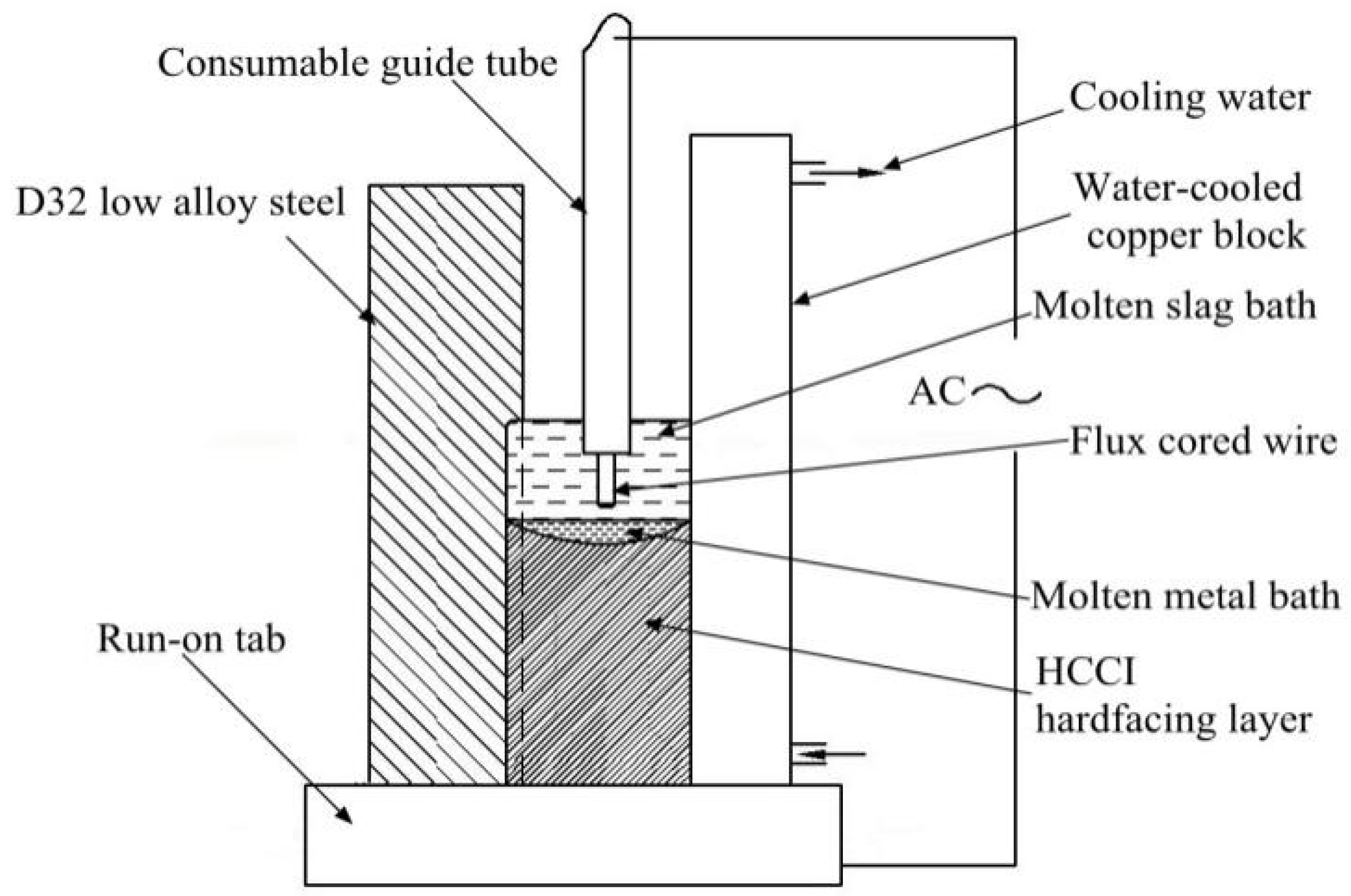
In this study, HCCI hardfacing layers were deposited on low alloy steel plate D32 (Thickness: 30 mm) by electroslag surfacing. The chemical composition of D32 and schematic of electroslag surfacing are listed in Table 1 and shown in Figure 1 respectively. The microstructure of D32 steel is ferrite and pearlite. During the surfacing process, the consumable guide tube (ISO-C101, Outer dia. 10 mm, inner dia. 4 mm) was inserted successively and vertically in the electroslag surfacing plate cavity. The cavity contains a 30 × 30 mm2 water-cooled copper block and a run-on tab. The run-on tab is connected to the power supply. The other pole of the electrical power is connected to the guide tube. For the first step of the process, some slags (Sintered base CaF2-CaO-Al2O3) were inserted in the run-on tab and then melted by turning on the power (U-40 V, I-320 A). The liquid slag filled the plate cavity. Afterwards, more slags were continuously added to the slag bath with the aim of increasing the electrical resistance. The slags were used for heating the solid material and producing a controlled molten metal bath from the consumable guide tube and flux cored wire. To investigate the effect of V additive on HCCI hardfacing layers, the mass fraction of ferrovanadium added into the flux cored wire was 0 wt %, 2 wt %, 4 wt % and 6 wt % respectively. The chemical contents of each group are listed in Table 2.
The hardfacing samples for metallography were polished to mirror finish and etched with Villella’s reagent (5 mL HCl, 1 g picric acid in 100 mL ethanol) for 30 s to reveal the microstructure. The microstructure of samples was characterized using an optical microscope (OM) and scanning electron microscope (SEM). The area fraction of M7C3 carbides present in the microstructure was measured by Image-Pro-Plus using digitalized pictures. The average carbide areas A at the position were used to determine the refining effect of vanadium on the carbides, which can be described by Equation (1). Where S is the area of the carbides, μm2; n is the number of the carbides in one image. It can be seen that the smaller the A, the finer the carbides. With this arrangement, 20 images of each specimen at magnification of 500 times are randomly selected and processed for the calculation of A.
A = S/n
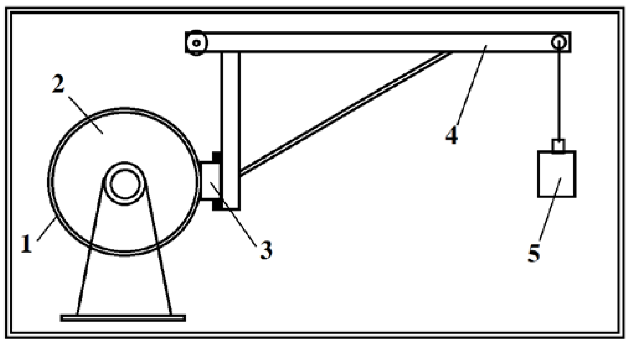
The phase composition of the samples was studied by X-ray diffractometer (XRD) with Cu rotating anode. The composition of carbide and the matrix was measured by using atom probe tomography. The Fe-C equilibrium phase diagram with different V additive was calculated by softwares Thermo-Calc (Version: P, databases: TCFE2, Stockholm, Sweden) and JMatPro (Version: 7.0, Guildford, UK). in this work. The hardness of different hardfacing layers was measured by conventional Rockwell tester in C scale (1470 N load and a diamond cone indenter typical for this scale). The abrasive wear behavior of HCCI hardfacing layer was investigated by the belt sander of type P40-X. The wear tests were performed with a standard ASTM G65-2004. As shown in Figure 2, rounded quartz particles on the belt were with mean diameter between 100 μm and 145 μm. The belt was changed after each test. The normal loads, rate of revolution and wear distance for each sample were 100 N, 240 r/min and 200 m, respectively. The weight loss of each specimen was measured on an electronic balance with the accuracy of 0.1 mg. The wear surface of each sample was observed by SEM.
3. Results and Discussion
3.1. Interface of the HCCI Electroslag Hardfacing Layer and Low Alloy Steel
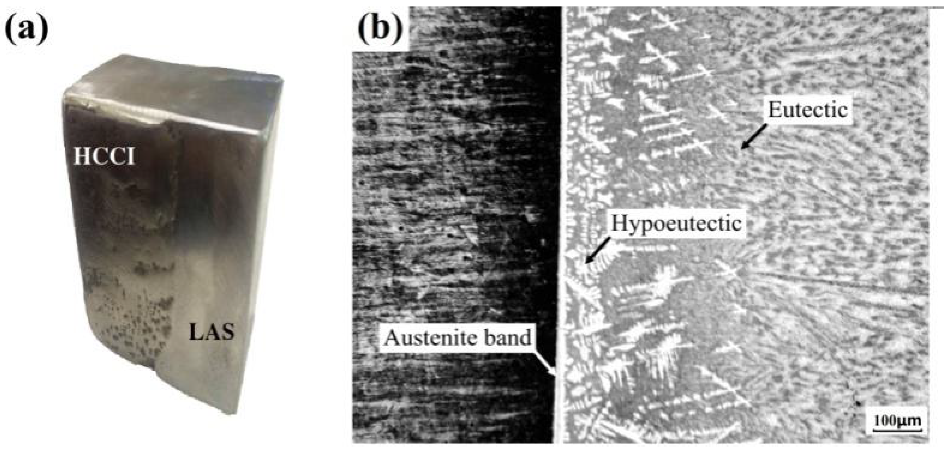
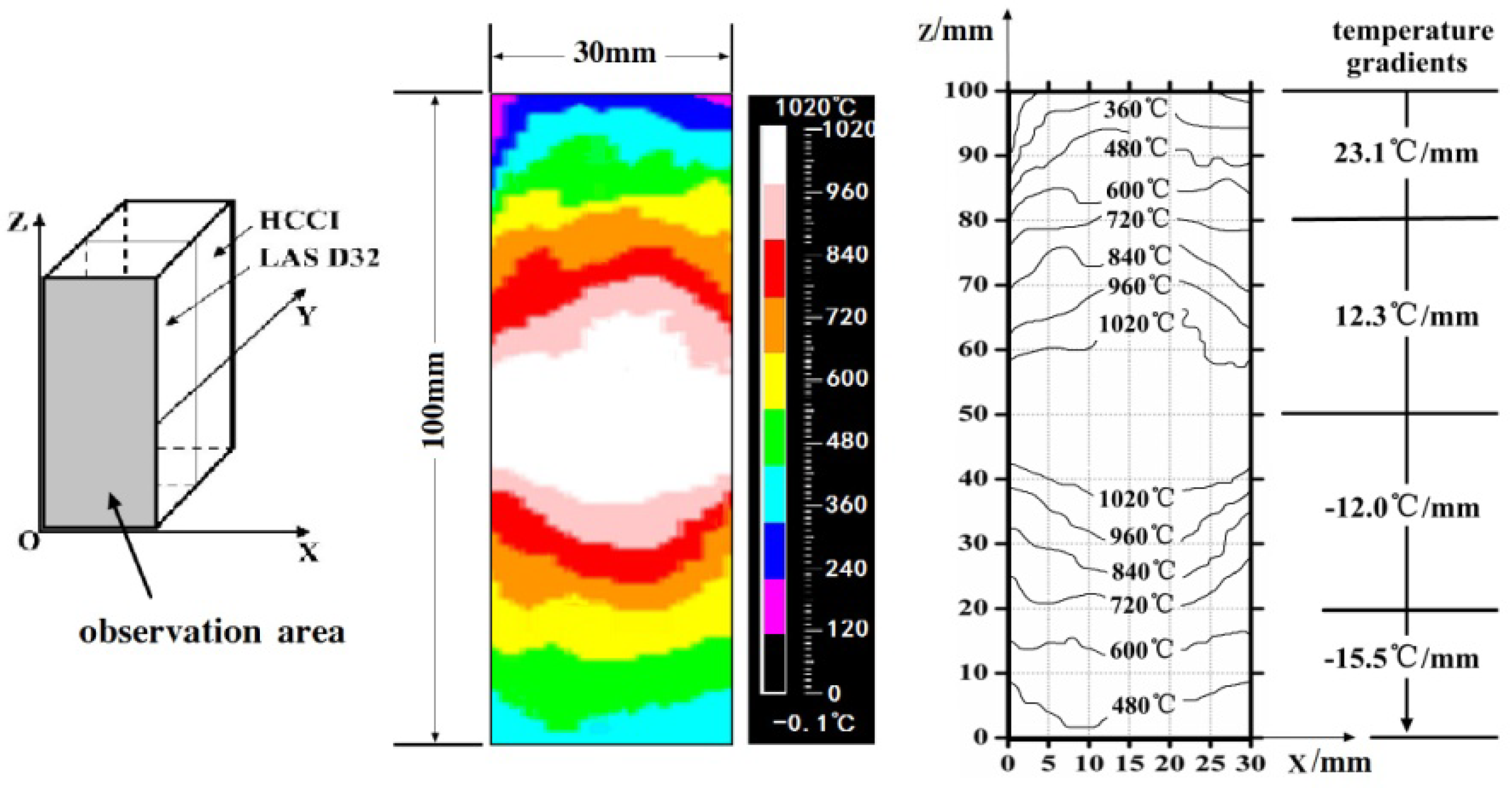
The interface between HCCI hardfacing layer and low alloy steel is found defect-free as shown in Figure 3a. Figure 3b shows that an austenitic band is formed in the interface, adjacent to which is hypoeutectic microstructure of primary austenite and eutectic mixture. However, the fraction of primary austenite decreases with distance away from the interface. Because of the variation of microstructure, a perfect metallurgical bonding between HCCI and low alloy steel is obtained. After electroslag surfacing, the microstructure of substrate is still ferrite and pearlite. In addition, the temperature filed of electroslag surfacing was measured by infrared imaging device as shown in Figure 4. The temperature gradients on both X and Z direction are less than 23.1 °C/mm. With the assistance of software JMatPro, the maximun thermal stress is calculated as 29.5 MPa, which is much less than the yields stress of the substrate (REh > 365 MPa [24]). So electroslag surfacing is an effective method of depositing HCCI hardfacing layer on low alloy steel that produces sound interface.
3.2. Microstructure of V Alloyed HCCI Hardfacing Layers
Detailed microstructural analysis of HCCI hardfacing layers with different V content has been investigated. OM micrographs are showing in Figure 5, whereas phase diagram shown in Figure 6, is calculated to understand the effect of V on microstructure.
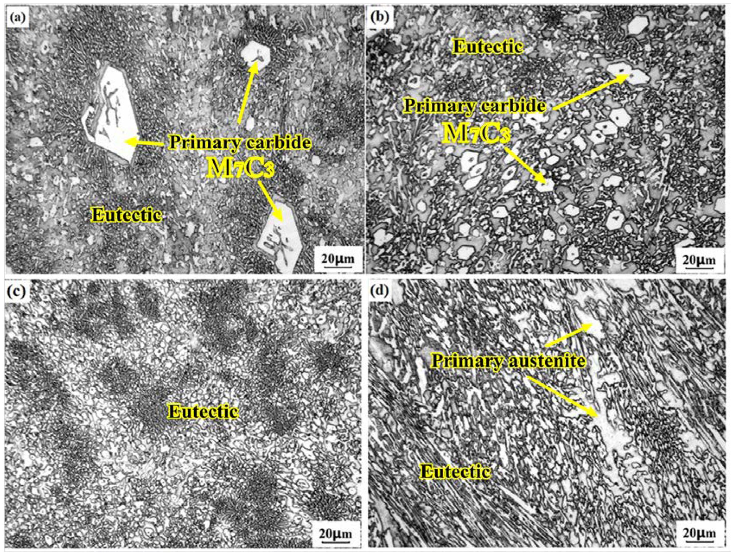
Figure 5a shows that without the V additive, the microstructure is consisting of eutectic and bulky primary M7C3 carbides. Figure 6a illustrates that the solidification starts with the formation of primary carbide M7C3 at 1300 °C. When the temperature is decreased to 1278 °C, the austenite (γ) and M7C3 carbides simultaneously develop and form the eutectic.
The microstructure of HCCI hardfacing layer with 0.83 wt % V is still consisting of eutectic and primary M7C3 as shown in Figure 5b; however, the primary carbides are refined as compared to Figure 5a. Figure 6b shows the eutectic point shifts to the right side in the phase diagram. Therefore, the temperature range of “L + M7C3” phase zone is smaller than the temperature range shown in Figure 6a, so the grain growth time of primary carbides is shorter accordingly.
Figure 5c shows that when the V concentration is raised to 1.50 wt %, the microstructure is eutectic. As shown in Figure 6c, the C content of eutectic point is 3.6 wt %, which is same to the C content of HCCI hardfacing layers. So the formed microstructure is eutectic only.
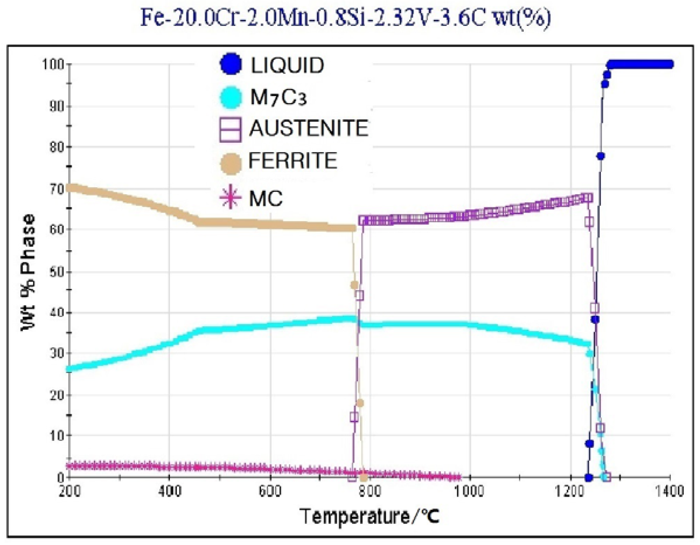
The microstructure of HCCI hardfacing layer with 2.32 wt % V is consisting of primary austenite and eutectic as shown in Figure 5d. Figure 6d shows that when the V content is 2.32 wt %, the position of eutectic point moves to the right side a little more. The solidification of HCCI passes through the “L+γ” and “L+γ+M7C3” phase regions sequentially, so primary austenite and eutectic microstructure is obtained after cooling.
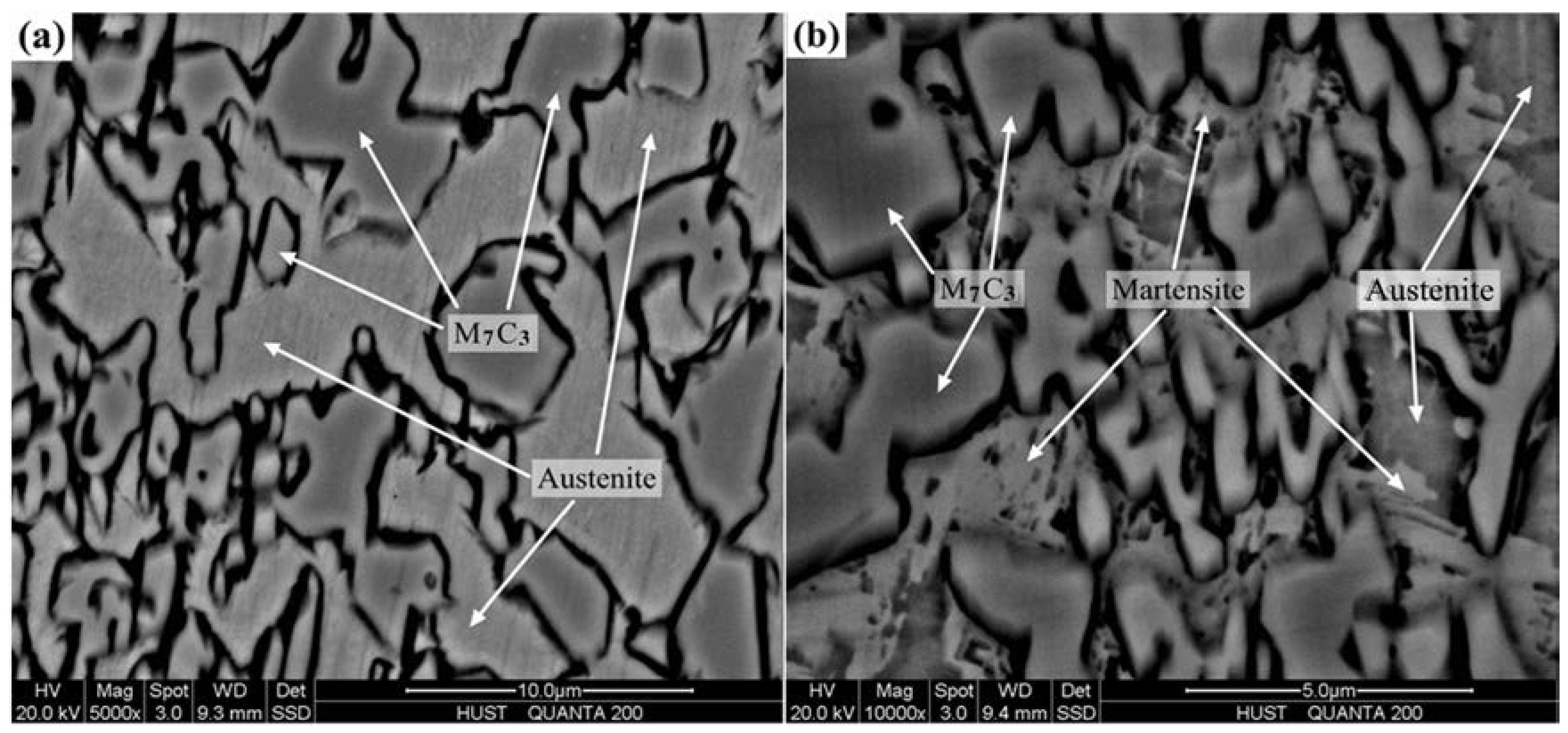
The X-ray diffraction (XRD) spectrum of hardfacing layers with varied V content is shown in Figure 7. Line (a) shows that the 3.6C-20Cr-Fe HCCI hardfacing layer contains M7C3 and austenite phase. Line (b), (c) and (d) show that by increasing V, martensite is formed in the hardfacing layers. As shown in Figure 8a, the eutectic colony in 3.6C-20Cr-Fe hardfacing layer comprises of eutectic austenite and carbides. While in 3.6C-20Cr-Fe-1.50V hardfacing layer, as shown in Figure 8b, the eutectic colony comprises of eutectic austenite and plate martensite surrounding eutectic carbides. This is because after adding V, more eutectic carbides are formed in the hardfacing layer, so the C and Cr contents in the austenite are decreasing, which has raised the Ms temperature of austenite and promoted the transformation of martensite [4].
From the above discussion, the microstructure of 3.6C-20Cr-Fe hardfacing layer is primary carbides and eutectic. With the V content increasing, the eutectic point moves to the right side, the eutectic area is increasing until the microstructure of hardfacing layer is only eutectic. When the V content exceeds the limited value, primary austenite and eutectic colonies formed in the microstructure. In addition, V alloying also promotes the formation of martensite in the HCCI hardfacing layers.
3.3. Effect of V on Carbides in HCCI Hardfacing Layers
3.3.1. Carbide Types
Figure 6 shows that only M7C3 type carbides are formed in the 3.6C-20Cr-Fe hardfacing layer. When 0.83 wt % and 1.50 wt % V are added, carbide in the hardfacing layers is M7C3. When the V content is 2.32 wt %, carbides in the hardfacing layers are M7C3 and MC. Energy dispersive spectroscopy (EDS) analysis of the matrix, M7C3 and MC are performed as shown in Figure 9 and Figure 10, and the results are shown in Table 3. By comparing Figure 9e,f, it can be seen that a little of V is dissolved in austenite, while V is mostly existed in M7C3 carbides. As shown in Table 3, the chemical composition of M7C3 in 3.6C-20Cr-Fe HCCI hardfacing layer is (Cr4.7Fe2.3)C3. With increasing V content to 0.83 wt % and 1.50 wt %, V atoms has substituted a part of Cr and Fe atoms into M7C3, the composition of which is (Cr4.6Fe2.2V0.2)C3 and (Cr4.5Fe2.1V0.4)C3, respectively. With increasing V content further to 2.32 wt %, more V atoms has replaced Cr atoms in the M7C3 carbide and its chemical composition is (Cr4.4Fe2.1V0.5)C3. It is well known that the atomic number of vanadium and chromium are 23 and 24, respectively. Their atomic radii are similar, but the electrons in the d layer of the vanadium atom are less than chromium atom. So the vanadium have stronger affinity with carbon than chromium, thereby V can replace a part of Cr in M7C3 type carbides.
When V content is 2.32 wt %, the amount of V solid solution in austenite reaches the limit, and the content of V in M7C3 carbide also reaches the saturation limit. At this time, as shown in Figure 10, the excess V is present in MC carbides which are precipitated from austenite. Figure 11 shows the equilibrium phase mass friction of the 3.6C-20Cr-Fe-2.32V HCCI hardfacing layer. It illustrates that the precipitation temperature of MC carbides is almost 990 °C, which is lower than the solidus temperature 1240 °C. So the MC carbides are precipitated from austenite as secondary carbides. EDS reveals that these MC secondary carbides are enriched in V and Cr elements with the chemical formula of (Cr0.23V0.77)C. The same type of carbide was found by de Mello [25] and Mirjana M. Filipović [15] in iron-chromium-carbon-vanadium white cast irons.
In the HCCI hardfacing alloy, the formation of carbides is related to the system energy. Thermodynamics can be used to analyze the precipitation possibility of VC carbides. The reactions equation and free energy of VC can be described in Equation (2):
where is the Gibbs free energy of V, T is the Kelvin temperature.
The energy change ΔG in the formation of VC carbide can be calculated using the Gibbs free energy given by Equation (3):
where, fV and fC are the activity coefficients of V and C, respectively. ωV and ωC are the mass fractions of V and C in the hardfacing alloy. When the equilibrium reaches, then the activity coefficient can be expressed as:
where, is the interaction coefficient of the j element with the x element, whereas the activity coefficient of V and C can be expressed as:
ΔG = ΔG0 − RT ln(fVωVfCωC) = ΔG0 − RT (lnfV + lnωV + lnfC + lnωC)
The interaction coefficient of alloying elements in molten iron at 1600 °C is shown in Table 4 [26].
By substituting the composition of the HCCI hardfacing layer and the relevant data from Table 4 into Equations (6) and (7), Equations (8) and (9) can be obtained as follows:
lnfV = 0.03 ωV + 2.75
lnfC = −0.18 ωV + 0.13
If the VC carbides form, the energy change
ΔG ≤ 0
By combining Equations (3), (8)–(10), we can get Equation (11):
0.15 ωV + lnωV ≥ 6.38
It is well known that, VC can be formed only when the mass fraction of V reaches the requirement of Equation (11). However, in this paper, the mass fraction of V is not enough to meet Equation (11). Therefore, VC cannot be formed as primary carbide.
Meanwhile, by assuming that VC precipitates from the molten iron as primary carbide, then the relation between the VC precipitation temperature and the mass fraction of V and C elements in electroslag molten iron can be expressed by Equation (12) [20].
where T is Kelvin temperature. [V] and [C] are mean mass fraction in molten iron of V and C elements, respectively. From Equation (12), the precipitated temperatures of VC carbides in Fe-Cr-C-V alloy with 0.83, 1.50 and 2.32 wt % V addition are 1238 K, 1314 K and 1375 K, respectively, which are lower than the precipitated temperature of primary phases and eutectic carbides. Therefore, VC carbides are the secondary carbides that precipitates from austenite.
lg [V][C] = (−105,800 + 94.5 T)/19.1 T
Therefore, when V is added to the HCCI hardfacing layer, as V has stronger affinity to C than Cr, most of the V is present in M7C3 carbides to replace Cr, while a little of V is dissolved into austenite. When V in both austenite and M7C3 carbides reached the saturated limit, (Cr0.23V0.77)C carbides precipitated in the austenite.
3.3.2. Area Fraction and Size of M7C3 Carbides
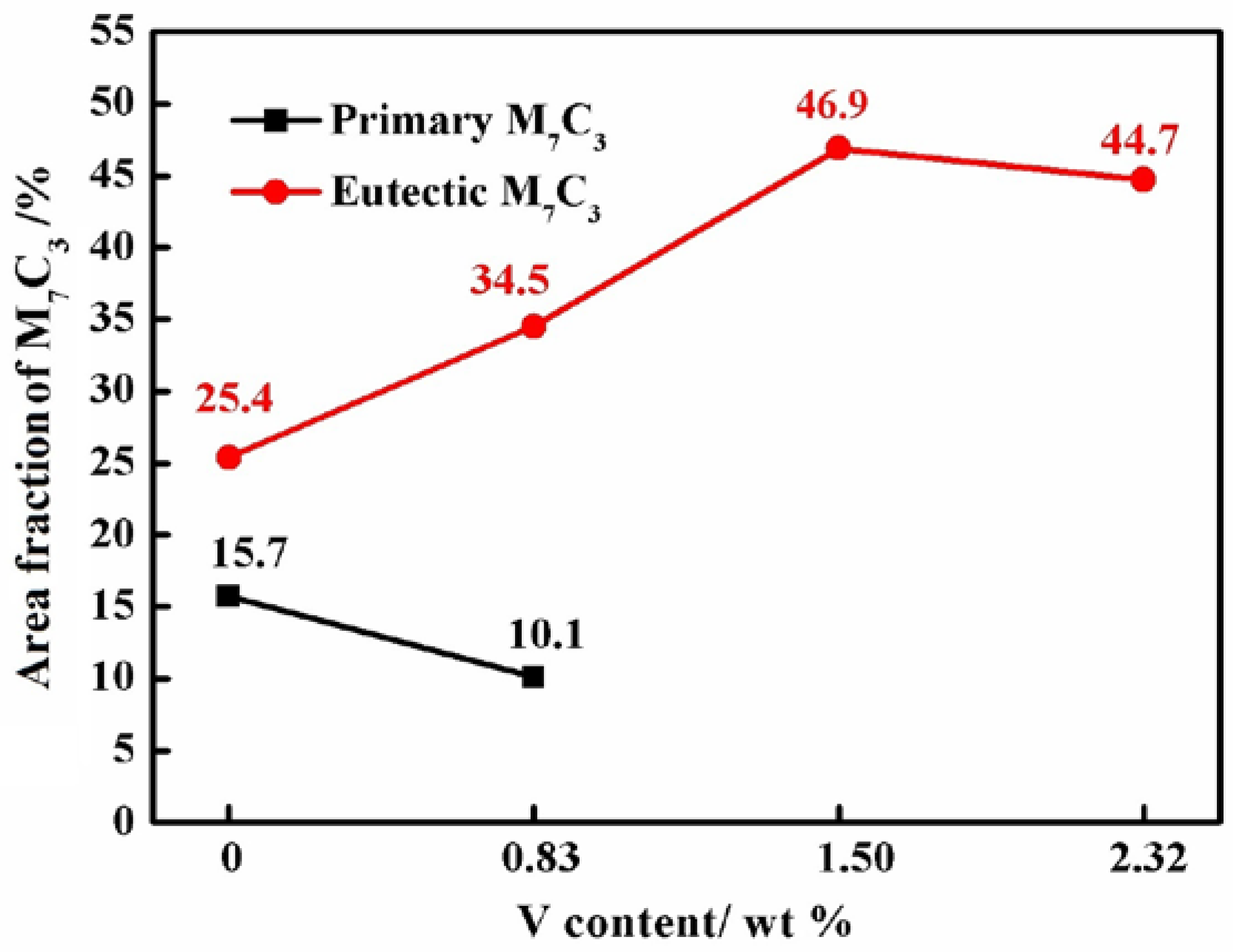
The area fractions of carbides against various V concentrated samples are show in Figure 12. It can be seen that, the area fraction of Primary M7C3 carbides and eutectic M7C3 carbides in 3.6C-20Cr-Fe HCCI hardfacing layer are 15.7% and 25.4%, respectively. When the V concentration is 0.83 wt %, the area fraction of primary carbides is decreased to 10.1% while the area fraction of eutectic carbides is increased to 34.5%. In 3.6C-20Cr-Fe-1.50V HCCI hardfacing layers no further primary carbide growth is observed. The hardfacing has the maximum carbides area fraction of 46.9%. By increasing the V concentration to 2.32%, with the formation of primary austenite, the area fraction of eutectic carbides is decreased to 44.7%.
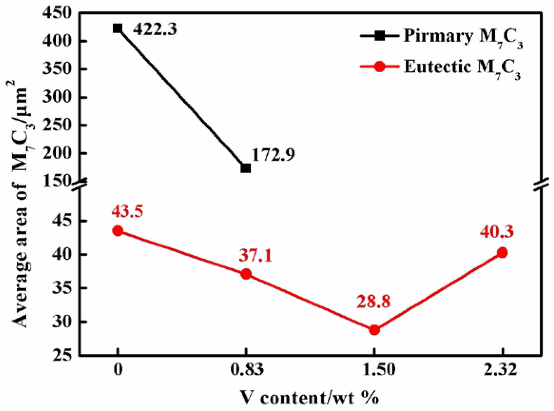
Figure 13 shows the size variation of M7C3 carbides in HCCI hardfacing layers with different V additive. The average area of primary M7C3 carbides and eutectic carbides in 3.6C-20Cr-Fe hardfacing layer is 422.3 μm2 and 43.5 μm2 respectively, determined by Equation (1). When the V content is 0.83 wt %, the areas of primary carbides and eutectic carbides are refined to 172.9 μm2 and 37.1 μm2, respectively. When the V concentration is raised to 1.50 wt %, the growth of the primary carbide is completely suppressed and the eutectic carbides are further refined. The microstructure is composed of small eutectic carbides with an average area of 28.8 μm2. However, when the V concentration is raised to 2.32 wt %, the solid-liquid coexistence temperature range becomes wider comparing to that with 1.50 wt % V additive. The eutectic carbides in 3.6C-20Cr-Fe-2.32V hardfacing layer have grown bigger with an average area of 40.3 μm2.
3.4. Hardness and Wear Resistance of V Alloyed HCCI Electroslag Hardfacing Layers
3.4.1. Hardness
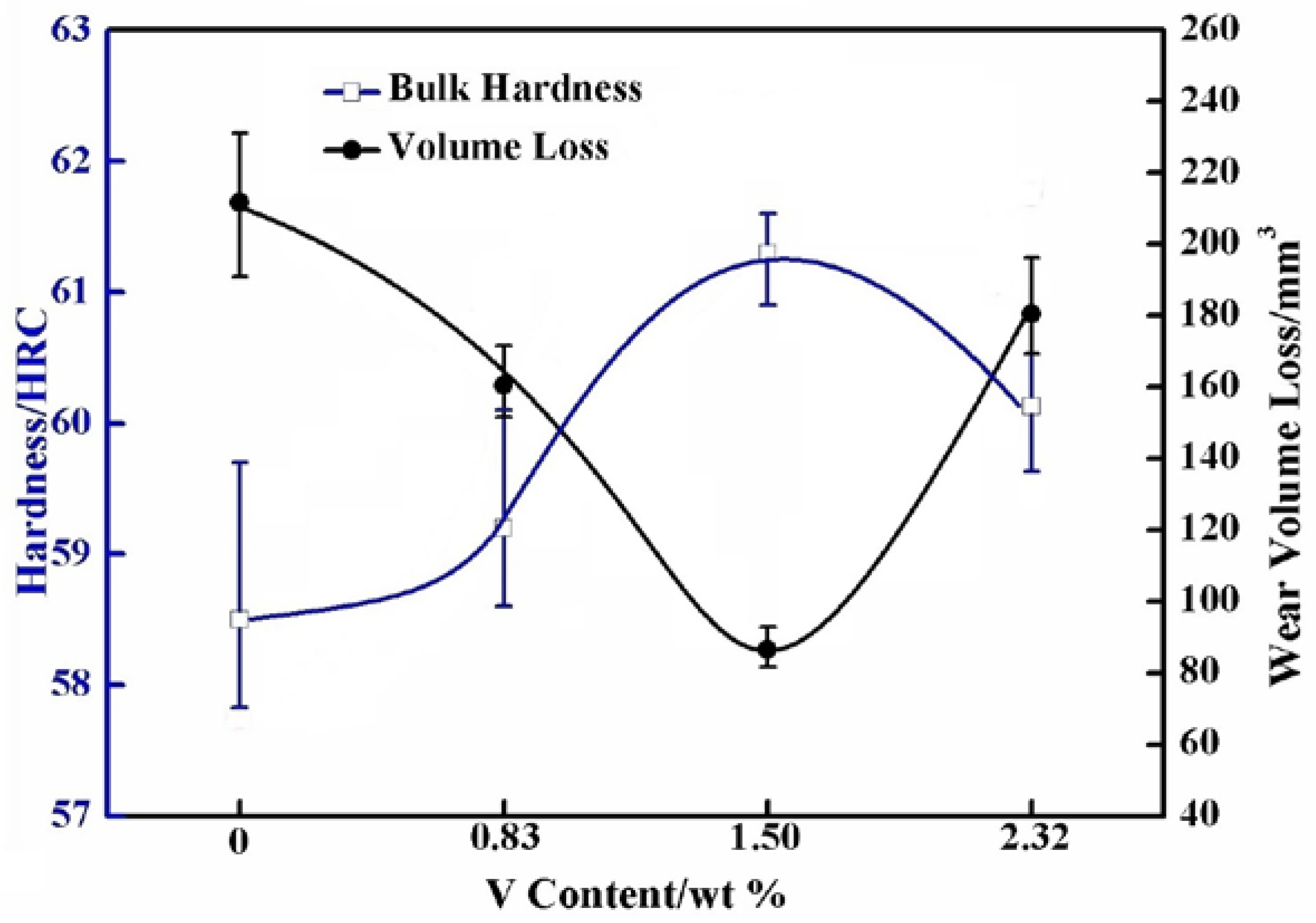
Figure 14 shows the hardness of HCCI hardfacing layer with different V content. The hardness of HCCI hardfacing layer without V is 58.5 HRC. When the V is 0.83 wt %, the primary carbide M7C3 is refined and the area fraction of eutectic carbides is increased. Carbides distribution is more uniform in the hardfacing layer, which has raised the hardness up to 59.2 HRC. As V is further increased to 1.50 wt %, the content of carbides is increased and all the M7C3 carbides are fine eutectic carbides in the microstructure. In this case, the highest hardness of 61.2 HRC is achieved. When the V is 2.32 wt %, the formation of soft austenite phase and the grain coarsening have decreased the bulk hardness of hardfacing to 60.1 HRC.
3.4.2. Wear Resistance
Figure 14 shows that the variation in the wear resistance is consistent with the hardness. The 3.6C-20Cr-Fe hardfacing layer has the highest wear volume loss of 211 mm3. As the primary carbides content is decreasing and the eutectic carbides content is increasing in the hardfacing layer, the wear volume loss of 3.6C-20Cr-Fe-0.83V hardfacing layer is decreasing to 160 mm3. The 3.6C-20Cr-Fe-1.50V hardfacing layer with eutectic microstructure has the least wear volume of 86 mm3, which is only 40% of the 3.6C-20Cr-Fe hardfacing sample. Whereas, the formation of soft austenitic dendrites phase in the microstructure of 3.6C-20Cr-Fe-2.32V HCCI hardfacing layer has also increased the wear volume significantly to 181 mm3.
Under normal conditions, the carbide with small size and uniform distribution in matrix show good wear resistance [27,28]. It was observed that 3.6C-20Cr-Fe HCCI hardfacing layer contains coarse primary carbide which can be seen more clearly in Figure 15a. It has also been observed that the austenite region B with lower carbon and chromium contents is surrounding the primary carbide region C. During the wear process, the coarse carbide fracturing and spalling from the matrix under tangential stress [29]. This carbide fracture can be clearly observed in Figure 15b where the cracked primary carbide leaves a large polygonal cave in its original position. Meanwhile the cracked M7C3 carbide particles, rolling on the wear surface, exacerbate the wear.
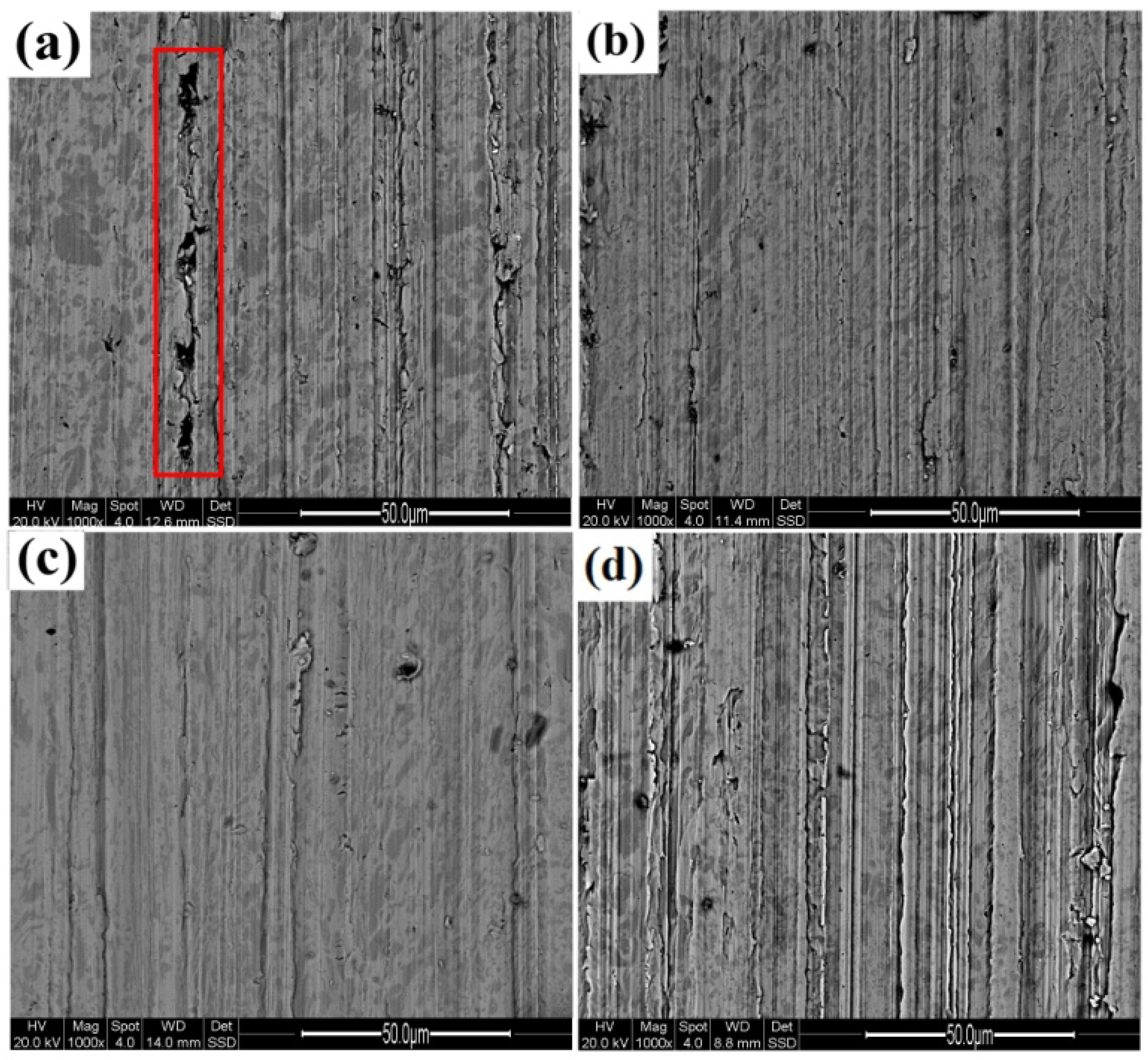
Whereas the red box marked in Figure 16a shows that in the 3.6C-20Cr-Fe HCCI hardfacing layer, the fractured primary carbides further act as secondary abrasive particles to cause more primary carbides breakage. When the V content is 0.83 wt %, carbides are refined, the content and size of primary carbides is decreased and more uniform eutectic carbides are formed. As shown in Figure 16b, the plow grooves on wear surface are shallower and finer than that showing in Figure 15a. When the V content is 1.50 wt %, fine eutectic carbides are distributed uniformly in the hardfacing layer, as shown in Figure 16c, the plow grooves on wear surface are more shallower and finer than that in Figure 16b, and no noticeable caves have been observed. When the V content reaches to 2.32 wt %, primary austenite is appeared in the microstructure and a decline in the hardness of the hardfacing layer is found, whereas the depth of the plow grooves is deeper, which indicates that the wear resistance is decreased further. However, because of the absence of coarse primary carbides, caves have not been observed on the wear surface as shown in Figure 16d.
4. Conclusions
(1) High chromium cast iron can be used for surfacing low alloy steel to form bimetallic material. The temperature gets evenly distributed in the workpiece during the electroslag surfacing process, therefore the interface between hardfacing layer and low alloy steel D32 is defect free.
(2) The microstructure of 3.6C-20Cr-Fe hardfacing layer is primary carbides and eutectic. With 0.83 wt % V, the primary carbides are refined and small amount of martensite formed in the microstructure. With 1.50 wt % V, the microstructure is a lot of eutectic and a little of martensite. The microstructure of 3.6C-20Cr-Fe-2.32V is primary austenite, martensite and eutectic.
(3) In V alloyed HCCI hardfacing layers, V can replace a part of Cr in M7C3 and (Cr4.4–4.7Fe2.1–2.3V0.2–0.5)C3 type carbides formed, while a little of V is dissolved into austenite. When V atoms in both austenite and M7C3 carbides reached the saturated limit, (Cr0.23V0.77)C carbides precipitate from the austenite.
(4) With the increase of V additive, the M7C3 carbides in the hardfacing layers are refined significantly. The eutectic carbides are refined with an average area of 28.8 μm2 when V content is 1.50 wt %. While when the V concentration is raised to 2.32 wt %, the eutectic carbides have grown bigger with an average area of 40.3 μm2.
(5) The HCCI hardfacing layer with 1.50 wt % V exhibited the highest hardness and lowest wear loss. It appears that the microstructural refinement by limiting the carbon content in the range of eutectic composition plays a predominant role in improving the wear resistance of the electroslag HCCI hardfacing layer.
Author Contributions
Conceptualization, H.W. and S.F.Y.; Investigation, H.W. and A.R.K.; Methodology, A.G.H.; Project administration, S.F.Y.; Supervision, S.F.Y.; Writing—original draft, H.W.; Writing—review and editing, H.W., A.R.K. and A.G.H.
Funding
This research received no external funding.
Acknowledgments
This research did not receive any specific grant from funding agencies in the public, commercial, or not-for-profit sectors. Here, the authors want to thank the technical support from the Analytical and Testing Center in Huazhong University of Science and Technology.
Conflicts of Interest
The authors declare no conflict of interest.
References
- Sharma, T.; Maria, S.; Dwivedi, D.K. Abrasive wear behavior of Fe-30Cr-3.6C overlays deposited on mild steel. ISIJ Int. 2005, 45, 1322–1325. [Google Scholar] [CrossRef]
- Correa, E.O.; Alcântara, N.G.; Tecco, D.G.; Kumar, R.V. The relationship between the microstructure and abrasive resistance of a hardfacing layer in the Fe-Cr-C-Nb-V system. Metall. Mater. Trans. 2007, 38, 1671–1680. [Google Scholar] [CrossRef]
- Zahiri, R.; Sundaramoorthy, R.; Patrick, L.; Subramanian, C. Hardfacing using ferro-alloy powder mixtures by submerged arc welding. Surf. Coat. Technol. 2014, 260, 220–229. [Google Scholar] [CrossRef]
- Tang, X.H.; Chung, R.; Pang, C.J.; Li, D.Y.; Hinckley, B.; Dolman, K. Microstructure of high (45 wt %) chromium cast irons and their resistances to wear and corrosion. Wear 2011, 271, 1426–1431. [Google Scholar] [CrossRef]
- Wang, H.; Yu, S.F. Influence of heat treatment on microstructure and sliding wear resistance of high chromium cast iron electroslag hardfacing layer. Surf. Coat. Technol. 2017, 319, 182–190. [Google Scholar] [CrossRef]
- Zhou, Q.; Su, J. Chromium Family of Wear Resistant Cast Iron; Xi’an Jiaotong University Press: Xi’an, China, 1986; pp. 111–112. [Google Scholar]
- Fulcher, J.K.; Kosel, T.H.; Fiore, N.F. The effect of carbide volume fraction on the low stress abrasion resistance of high Cr-Mo white cast irons. Wear 1983, 84, 313–325. [Google Scholar] [CrossRef]
- Sapate, S.; Rama Rao, A. Erosive wear behavior of weld hardfacing high chromium cast irons: Effect of erodent particles. Tribol. Int. 2006, 39, 206–212. [Google Scholar] [CrossRef]
- Zhi, X.H.; Liu, J.Z.; Xing, J.D.; Ma, S. Effect of cerium modification on microstructure and properties of hypereutectic high chromium cast iron. Mater. Sci. Eng. A 2014, 603, 98–103. [Google Scholar] [CrossRef]
- Wang, Y.; Gou, J.F.; Chu, R.Q.; Zhen, D.; Liu, S. The effect of nano-additives containing rare earth oxides on sliding wear behavior of high chromium cast iron hardfacing layers. Tribol. Int. 2016, 103, 102–112. [Google Scholar] [CrossRef]
- Zhi, X.H.; Xing, J.D.; Fu, H.G.; Xiao, B. Effect of niobium on the as-cast microstructure of hypereutectic high chromium cast iron. Mater. Lett. 2008, 62, 857–860. [Google Scholar] [CrossRef]
- Wu, X.J.; Xing, J.D.; Fu, H.G.; Zhi, X. Effect of titanium on the morphology of primary M7C3 carbides in hypereutectic high chromium white iron. Mater. Sci. Eng. A 2007, 457, 180–185. [Google Scholar] [CrossRef]
- Filipovic, M.; Kamberovic, Z.; Korac, M.; Gavrilovski, M. Microstructure and mechanical properties of Fe-Cr-C-Nb white cast irons. Mater. Des. 2013, 47, 41–48. [Google Scholar] [CrossRef]
- Filipovic, M.; Romhanji, E.; Kamberovic, Z.; Korac, M. Matrix microstructure and its micro-analysis of constituent phases in as-cast Fe-Cr-C-V alloys. Mater. Trans. 2009, 50, 2488–2492. [Google Scholar] [CrossRef]
- Mirjana, M. Filipović, Iron-chromium-carbon-vanadium white cast irons: the microstructure and properties. Hem. Ind. 2014, 68, 413–427. [Google Scholar] [CrossRef]
- Wu, L.L.; Xiao, F.R.; Wang, Y.C.; Liang, C.B.; Sun, G.P.; Liao, B. Effect of vanadium on microstructure and wear resistance of Ni-Cr alloyed cast iron. Int. J. Cast Met. Res. 2013, 26, 176–183. [Google Scholar] [CrossRef]
- Arnoldo, B.J. Microstructure of vanadium-, niobium-and titanium-alloyed high-chromium white cast irons. Int. J. Cast Met. Res. 2001, 13, 343–361. [Google Scholar] [CrossRef]
- Waleed, E.; Rashad, R.; Sayed, E.; Saied, E. Influence of Vanadium and Boron Additions on the Microstructure, Fracture Toughness, and Abrasion Resistance of Martensite-Carbide Composite Cast Steel. Adv. Mater. Sci. Eng. 2016, 2016, 1203756. [Google Scholar] [CrossRef]
- Bedolla-Jacuinde, A.; Guerra, F.V.; Mejía, I.; Zuno-Silva, J.; Rainforth, M. Abrasive wear of V-Nb-Ti alloyed high-chromium white irons. Wear 2015, 332–333, 1006–1011. [Google Scholar] [CrossRef]
- Qi, X.; Jia, Z.; Yang, Q.; Yang, Y. Effects of vanadium additive on structure property and tribological performance of high chromium cast iron hardfacing metal. Sur. Coat. Technol. 2011, 205, 5510–5514. [Google Scholar] [CrossRef]
- Cemil, C. An investigation of the wear behaviors of white cast irons under different compositions. Mater. Des. 2006, 27, 437–445. [Google Scholar] [CrossRef]
- Radulovic, M.; Fiset, M.; Peev, K. The influence of vanadium on fracture toughness and abrasion resistance in high chromium white cast irons. J. Mater. Sci. 1994, 29, 5085–5094. [Google Scholar] [CrossRef]
- Ogi, K.; Matsubara, Y.; Matsuda, K. Eutectic solidification of high chromium cast iron-eutectic mechanism of eutectic growth. AFS Trans. 1982, 89, 197–204. [Google Scholar]
- Liu, X.Y.; Piao, Z.M.; Wang, X.H.; Zhao, J.; Cao, Z.Q.; Li, H.; Lai, C.B.; Wu, B.; Xu, H.Q.; Huang, Z.Y.; et al. GB 712-2011, Ship and Ocean Engineering Structural Steel; Standards Press of China: Beijing, China, 2011. [Google Scholar]
- De Mello, J.D.B.; Durand-Charre, M.; Mathia, T. Abrasion mechanisms of white cast iron II: Influence of the metallurgical structure of V-Cr white cast irons. Mater. Sci. Eng. 1986, 78, 127–134. [Google Scholar] [CrossRef]
- Liang, Y.J.; Che, Y.C. Inorganic Thermodynamic Data Manual; North East University Press: Shen Yang, China, 1993; pp. 508–510. ISBN 7-81006-532-7. [Google Scholar]
- Radzikowska, J.M. Metallography and microstructures of cast iron. In ASM Handbooks: Metallography and Microstructures; ASM International: Novelty, OH, USA, 2004; pp. 565–587. [Google Scholar]
- Wu, H.Q.; Sasaguri, N.; Matsubara, Y.; Hashimoto, M. Solidification of Multi-Alloyed White Cast Iron: Type and Morphology of Carbides. Trans. Am. Fish. Soc. 1996, 140, 103–108. [Google Scholar]
- Hao, F.; Li, D.; Dan, T.; Ren, X.; Liao, B.; Yang, Q. Effect of rare earth oxides on the morphology of carbides in hardfacing metal of high chromium cast iron. J. Rare Earth 2011, 29, 168–172. [Google Scholar] [CrossRef]
Figure 1.
Schematic of the electroslag surfacing.

Figure 2.
Schematic of abrasion test apparatus. 1-sand belt, 2-Steel disc, 3-Specimen, 4-Ever arm, 5-Weight.
Figure 2.
Schematic of abrasion test apparatus. 1-sand belt, 2-Steel disc, 3-Specimen, 4-Ever arm, 5-Weight.

Figure 3.
Interface of the HCCI hardfacing layer (a) The macro-profile, (b) The micro-structure.

Figure 4.
Temperature filed of the back surface of D32 during the electroslag surfacing processing.

Figure 5.
Microstructure of 3.6C-20Cr-Fe HCCI hardfacing layers with different V, (a) 0 V, (b) 0.83 V, (c) 1.50 V, (d) 2.32 V.
Figure 5.
Microstructure of 3.6C-20Cr-Fe HCCI hardfacing layers with different V, (a) 0 V, (b) 0.83 V, (c) 1.50 V, (d) 2.32 V.

Figure 6.
Phase diagrams of the hardfacing layers with (a) 3.6C-20Cr-Fe, (b) 3.6C-20Cr-Fe-0.83V, (c) 3.6C-20Cr-Fe-1.50V, (d) 3.6C-20Cr-Fe-2.32V.
Figure 6.
Phase diagrams of the hardfacing layers with (a) 3.6C-20Cr-Fe, (b) 3.6C-20Cr-Fe-0.83V, (c) 3.6C-20Cr-Fe-1.50V, (d) 3.6C-20Cr-Fe-2.32V.
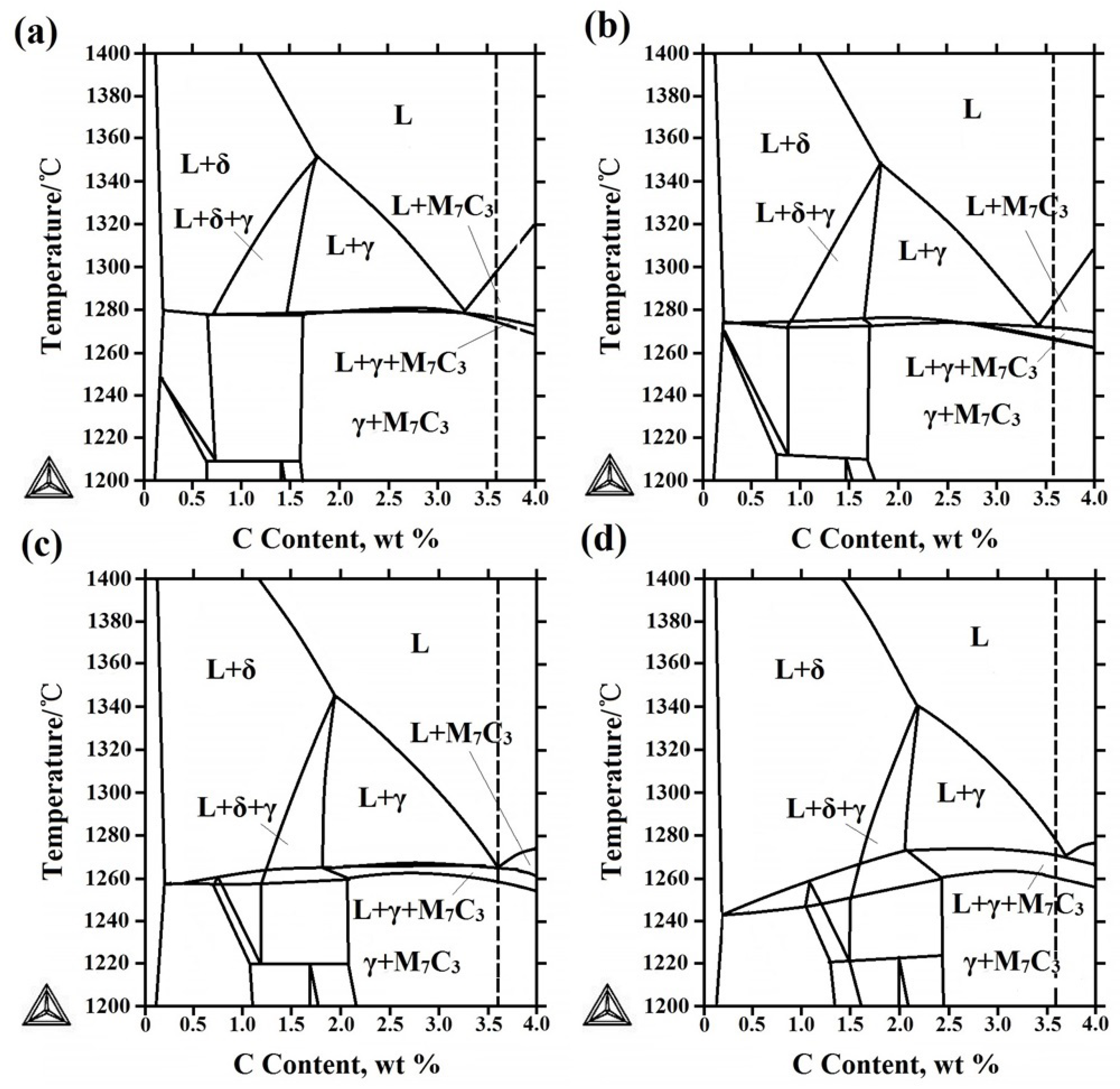
Figure 7.
XRD of the hardfacing layer with different V contents, (a) 0 V, (b) 0.83 V, (c) 1.50 V, (d) 2.32 V.
Figure 7.
XRD of the hardfacing layer with different V contents, (a) 0 V, (b) 0.83 V, (c) 1.50 V, (d) 2.32 V.
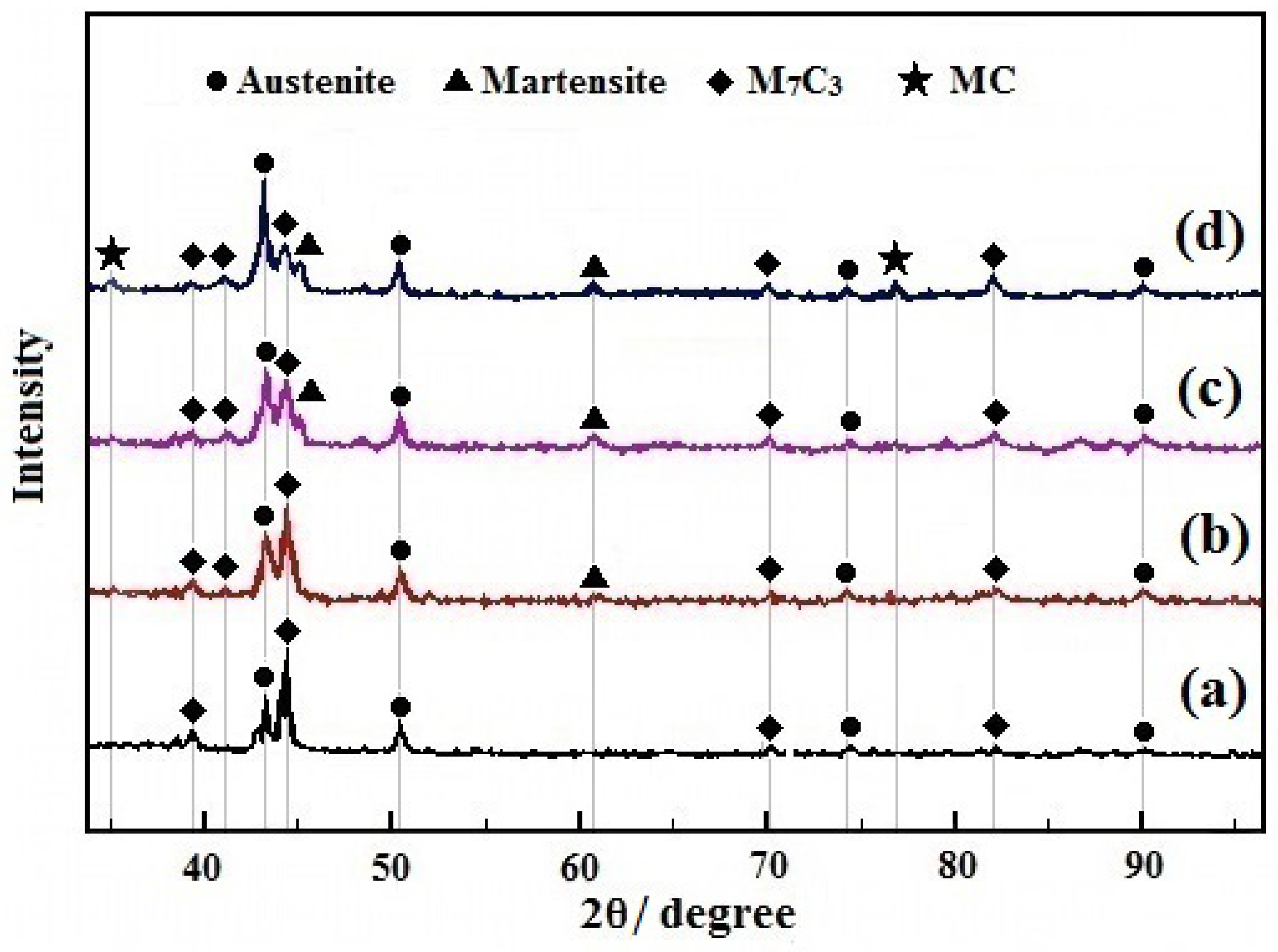
Figure 8.
Microstructure of eutectic zone of HCCI hardfacing layer, (a) 3.6C-20Cr-Fe, (b) 3.6C-20Cr-Fe-1.50V.
Figure 8.
Microstructure of eutectic zone of HCCI hardfacing layer, (a) 3.6C-20Cr-Fe, (b) 3.6C-20Cr-Fe-1.50V.

Figure 9.
EDS analysis of different phases in HCCI hardfacing layers with different V contents, 1-EDS test point of matrix, 2-EDS test point of M7C3 (a) 0 V, (b) 0.83 V, (c) 1.50 V, (d) 2.32 V, (e) EDS of matrix, (f) EDS of M7C3.
Figure 9.
EDS analysis of different phases in HCCI hardfacing layers with different V contents, 1-EDS test point of matrix, 2-EDS test point of M7C3 (a) 0 V, (b) 0.83 V, (c) 1.50 V, (d) 2.32 V, (e) EDS of matrix, (f) EDS of M7C3.
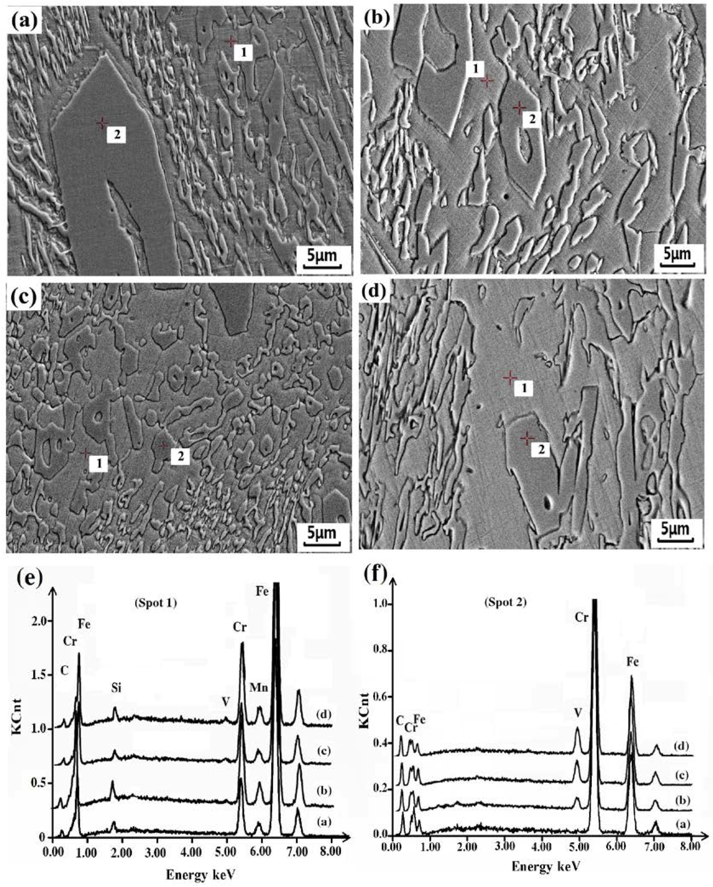
Figure 10.
EDS of MC carbide in 3.6C-20Cr-Fe-2.32V hardfacing layer.
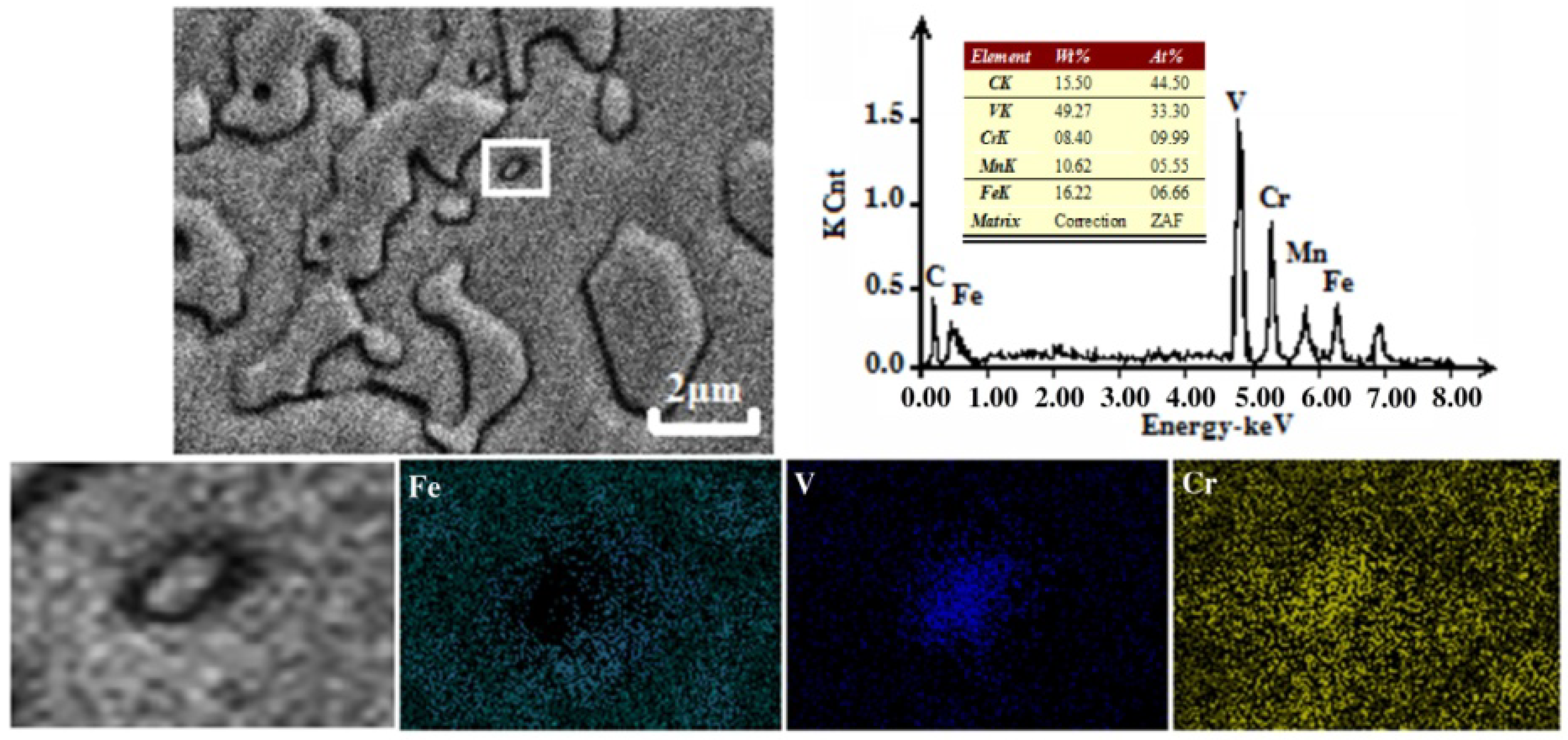
Figure 11.
Equilibrium phase mass friction of the 3.6C-20Cr-Fe-2.32V HCCI hardfacing layer.

Figure 12.
Area fraction of M7C3 carbides in different HCCI hardfacing layers.

Figure 13.
Average area of M7C3 carbides in different HCCI hardfacing layers.

Figure 14.
Changes in the hardness and wear volume loss of HCCI hardfacing layer.

Figure 15.
Morphology of the primary carbide in 3.6C-20Cr-Fe HCCI hardfacing layer, (a) before wear, (b) after wear.
Figure 15.
Morphology of the primary carbide in 3.6C-20Cr-Fe HCCI hardfacing layer, (a) before wear, (b) after wear.
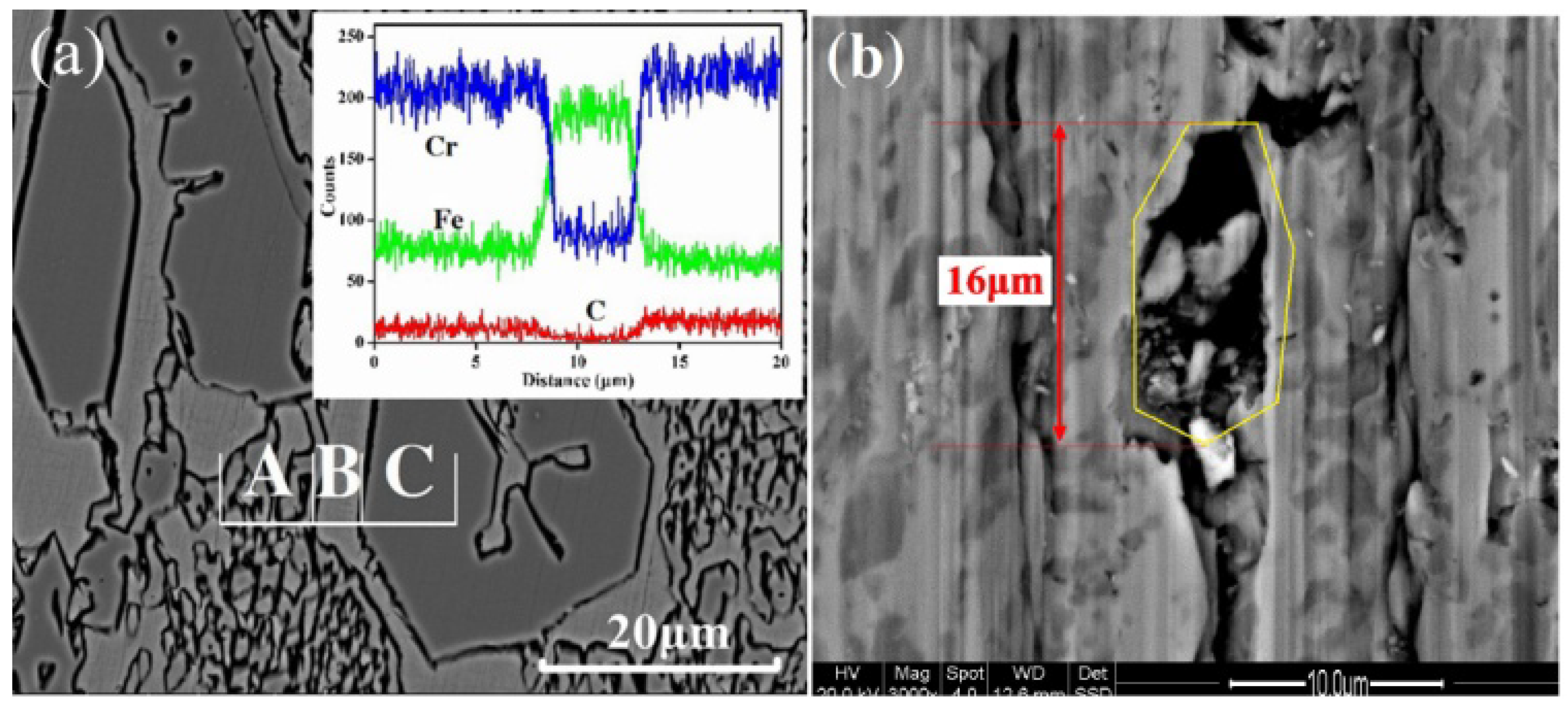
Figure 16.
Morphology of the wear surface of HCCI hardfacing layer with different V contents, (a) 0 V, (b) 0.83 V, (c) 1.50 V, (d) 2.32 V.
Figure 16.
Morphology of the wear surface of HCCI hardfacing layer with different V contents, (a) 0 V, (b) 0.83 V, (c) 1.50 V, (d) 2.32 V.

Table 1.
Chemical composition of D32 wt %.
| Materials | C | Si | Mn | P | S | Cu | Cr | Ni | Nb | V | Ti | Mo | Al | Fe |
|---|---|---|---|---|---|---|---|---|---|---|---|---|---|---|
| D32 | 0.13 | 0.22 | 1.30 | 0.01 | 0.01 | 0.32 | 0.20 | 0.39 | 0.04 | 0.08 | 0.02 | 0.05 | 0.02 | Bal. |
Table 2.
Chemical compositions of high chromium cast iron hardfacing layer wt %.
| Hardfacing | C | Cr | V | Si | Mn | Fe |
|---|---|---|---|---|---|---|
| 1# | 3.62 | 19.48 | -- | 0.86 | 2.31 | Bal. |
| 2# | 3.59 | 20.19 | 0.83 | 0.68 | 2.25 | Bal. |
| 3# | 3.58 | 19.40 | 1.50 | 0.68 | 2.06 | Bal. |
| 4# | 3.56 | 19.57 | 2.32 | 0.64 | 1.91 | Bal. |
Table 3.
Chemical component of carbides in HCCI hardfacing layers with different V.
| Hardfacing Layer | M7C3 | MC |
|---|---|---|
| 3.6C-20Cr-Fe | (Cr4.7Fe2.3)C3 | -- |
| 3.6C-20Cr-Fe-0.83V | (Cr4.6Fe2.2V0.2)C3 | -- |
| 3.6C-20Cr-Fe-1.50V | (Cr4.5Fe2.1V0.4)C3 | -- |
| 3.6C-20Cr-Fe-2.32V | (Cr4.4Fe2.1 V0.5)C3 | (Cr0.23V0.77)C |
Table 4.
The interaction coefficient of alloying elements in molten iron at 1600 °C.
| Alloying Elements | C | Cr | Si | Mn | V |
|---|---|---|---|---|---|
| 0.14 | −0.024 | 0.08 | −0.012 | −0.077 | |
| −0.34 | 0.042 | 0.015 |
© 2018 by the authors. Licensee MDPI, Basel, Switzerland. This article is an open access article distributed under the terms and conditions of the Creative Commons Attribution (CC BY) license (http://creativecommons.org/licenses/by/4.0/).
Share and Cite
MDPI and ACS Style
Wang, H.; Yu, S.F.; Khan, A.R.; Huang, A.G. Effects of Vanadium on Microstructure and Wear Resistance of High Chromium Cast Iron Hardfacing Layer by Electroslag Surfacing. Metals 2018, 8, 458. https://doi.org/10.3390/met8060458
AMA Style
Wang H, Yu SF, Khan AR, Huang AG. Effects of Vanadium on Microstructure and Wear Resistance of High Chromium Cast Iron Hardfacing Layer by Electroslag Surfacing. Metals. 2018; 8(6):458. https://doi.org/10.3390/met8060458
Chicago/Turabian StyleWang, Hao, Sheng Fu Yu, Adnan Raza Khan, and An Guo Huang. 2018. "Effects of Vanadium on Microstructure and Wear Resistance of High Chromium Cast Iron Hardfacing Layer by Electroslag Surfacing" Metals 8, no. 6: 458. https://doi.org/10.3390/met8060458
Note that from the first issue of 2016, this journal uses article numbers instead of page numbers. See further details here.