Study of Plasma Electrolytic Oxidation Coatings on Aluminum Composites

 , ,
, ,
Abstract
:1. Introduction
2. Materials and Methods
3. Results
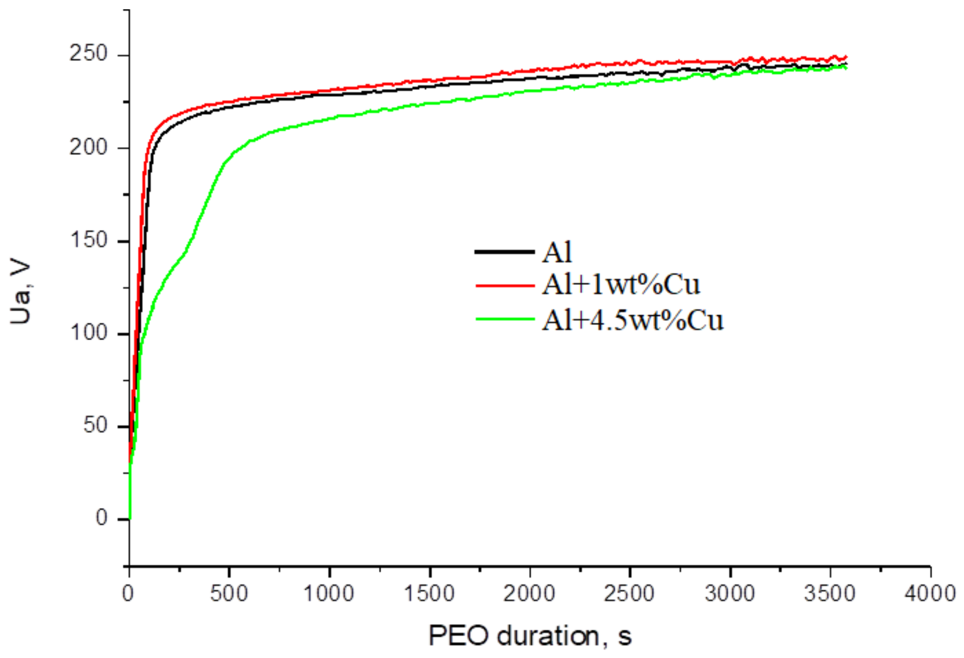
3.1. PEO Voltage-Time Response and the Thickness of the Coatings
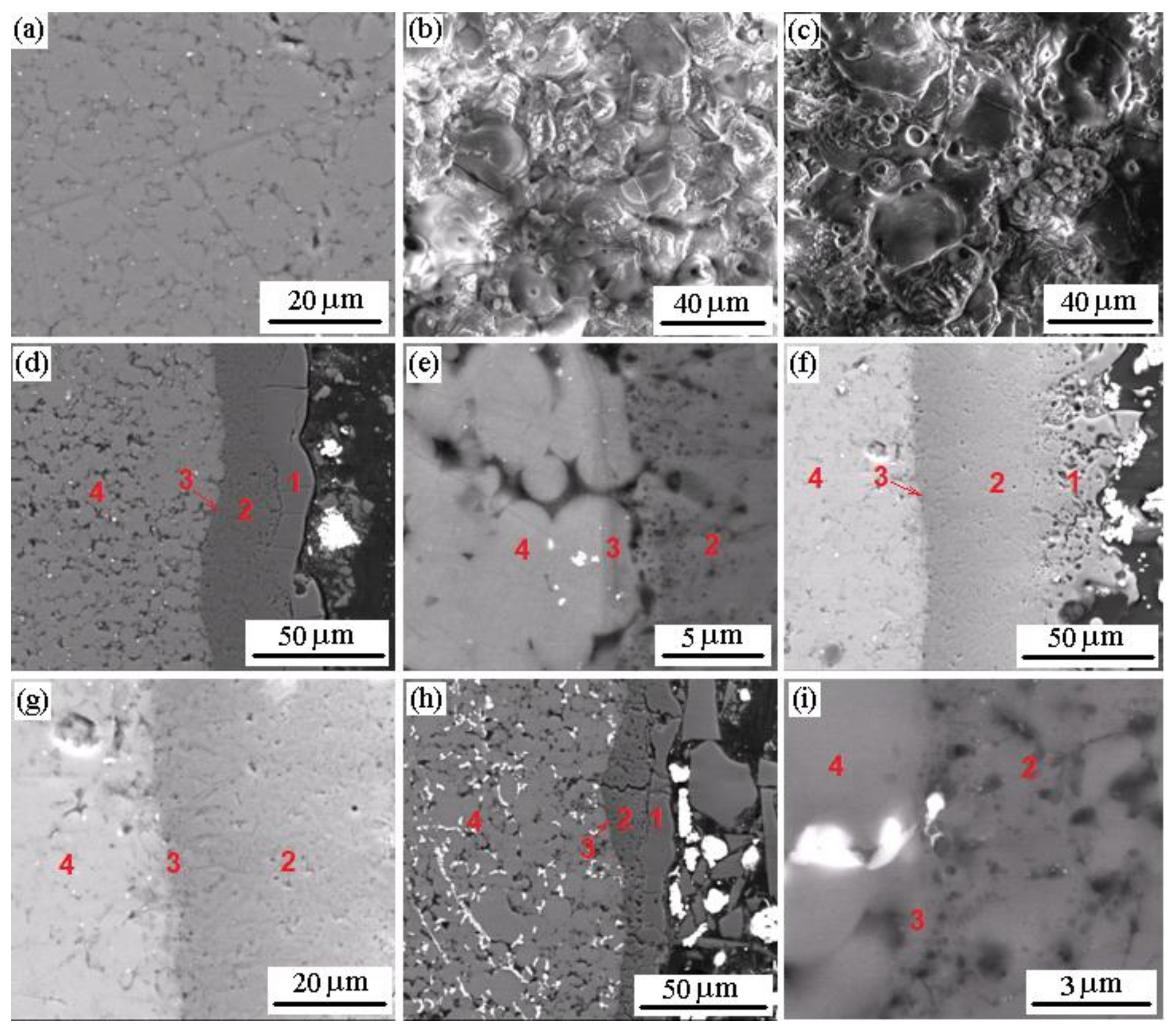
3.2. Surface and Cross-Section Microstructure of PEO Coatings
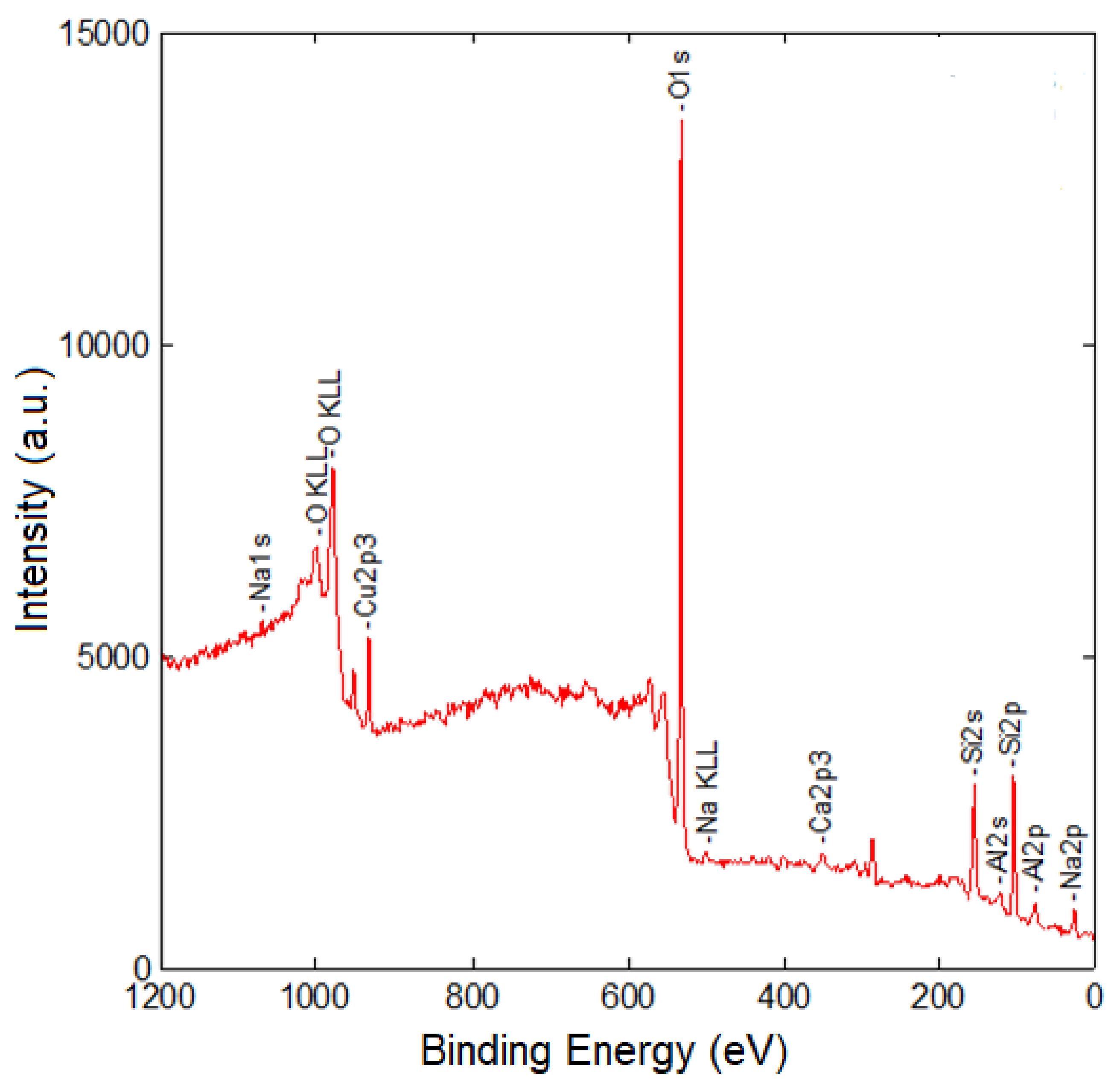
3.3. XPS Data
3.4. EDX Data
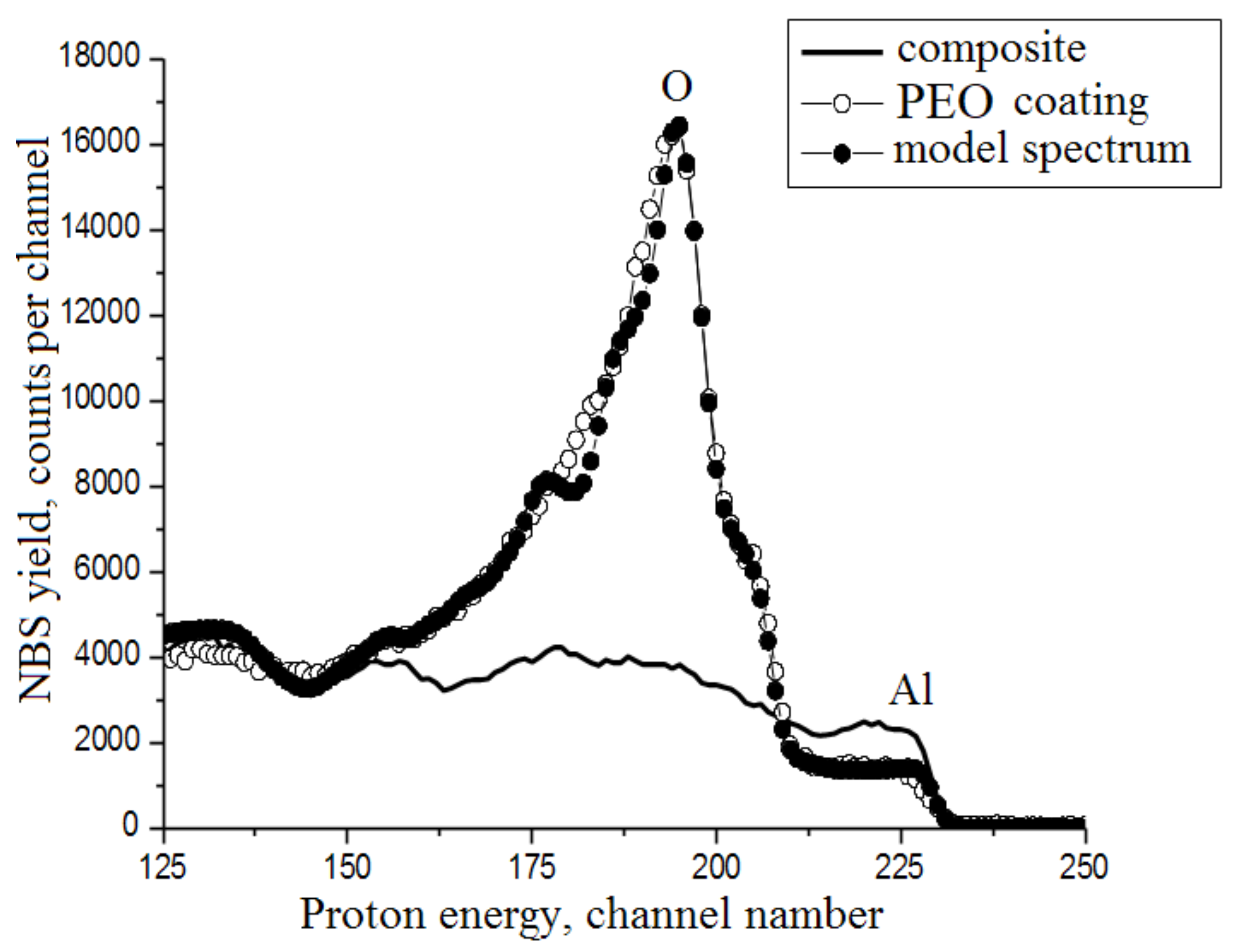
3.5. NBS Data
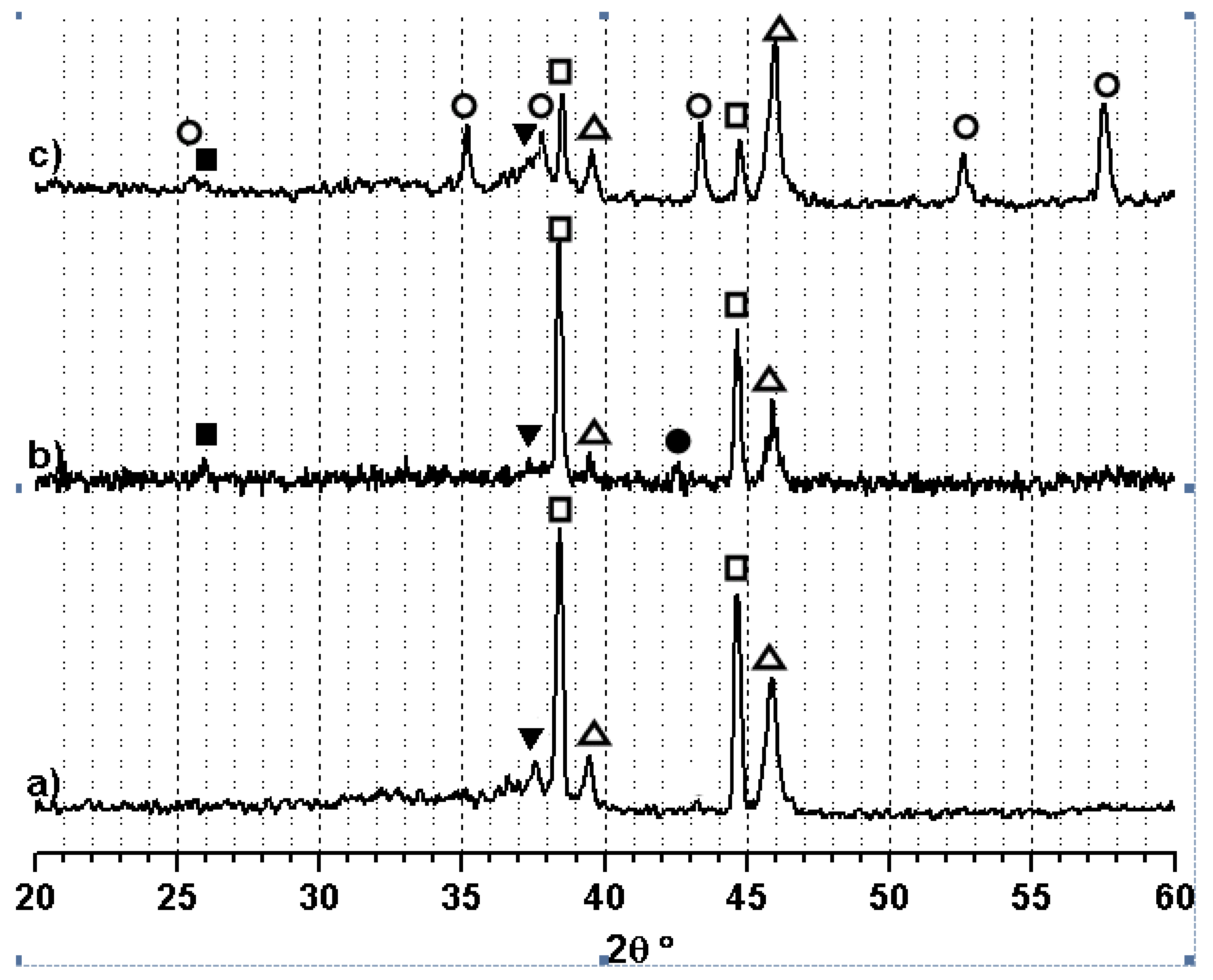
3.6. X-ray Diffraction Analysis
3.7. Microhardness of PEO Coatings
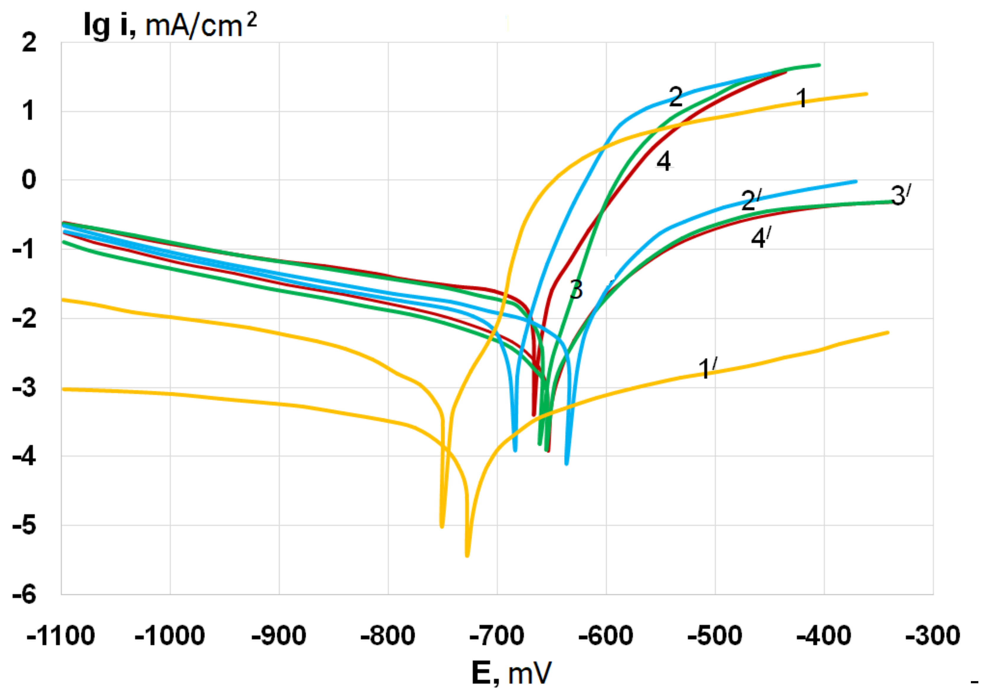
3.8. Electrochemical Behavior of PEO Coatings
4. Discussion
5. Conclusions
Author Contributions
Funding
Conflicts of Interest
References
- Bodunrin, L.O.; Alaneme, K.K.; Chown, L.H. Aluminum matrix hybrid composite: A review of reinforcement philosophies; mechanical, corrosion and tribological characteristic. J. Mater. Res. Technol. 2015, 4, 434–445. [Google Scholar] [CrossRef]
- Surappa, M.K. Aluminium Matrix Composites: Challenges and Opportunities. Sadhana 2003, 28, 319–334. [Google Scholar] [CrossRef]
- Agureev, L.E.; Kostikov, V.I.; Yeremeyeva, Z.V.; Barmin, A.A.; Rizakhanov, R.N.; Ivanov, B.S.; Ashmarin, A.A.; Laptev, I.N.; Rudshteyn, R.I. Powder aluminum composites of Al–Cu system with micro-additions of oxide nanoparticles. Inorg. Mater. Appl. Res. 2016, 7, 687–690. [Google Scholar] [CrossRef]
- Lurie, S.; Volkov-Bogorodskiy, D.; Solyaev, Y.; Rizahanov, R.; Agureev, L. Multiscale modelling of aluminium-based metal–matrix composites with oxide nanoinclusions. Comput. Mater. Sci. 2016, 116, 62–73. [Google Scholar] [CrossRef]
- Kang, Y.C.; Chan, S.L.-I. Tensile properties of nanometric Al2O3 particulate-reinforced aluminum matrix composites. Mater. Chem. Phys. 2004, 85, 438–443. [Google Scholar] [CrossRef]
- Ma, Z.Y.; Tjong, S.C.; Li, Y.L.; Liang, Y. High temperature creep behavior of nanometric Si3N4 particulate reinforced aluminium composite. Mater. Sci. Eng. A 1997, 225, 125–134. [Google Scholar] [CrossRef]
- Aranda, B.; Cuevas, F.G.; Cintas, J.; Herrera-Garcia, M.; Urban, P. Effect of Copper Addition on Pitting Corrosion of MA-Al. Acta Phys. Pol. A 2016, 129, 788–791. [Google Scholar] [CrossRef]
- Osório, W.R.; Freire, C.M.; Caram, R.; Garcia, A. The role of Cu-based intermetallics on the pitting corrosion behavior of Sn–Cu, Ti–Cu and Al–Cu alloys. Electrochim. Acta 2012, 77, 189–197. [Google Scholar] [CrossRef]
- Na, K.-H.; Pyun, S.-I. Comparison of susceptibility to pitting corrosion of AA2024-T4, AA7075-T651 and AA7475-T761 aluminium alloys in neutral chloride solutions using electrochemical noise analysis. Corros. Sci. 2008, 50, 248–258. [Google Scholar] [CrossRef]
- Apelfeld, A.V.; Belkin, P.N.; Borisov, A.M.; Vasin, V.A.; Krit, B.L.; Ludin, V.B.; Somov, O.V.; Sorokin, V.A.; Suminov, I.V.; Frantskevich, V.P. Modern Technologies for Modification of Materials Surface and Formation of Protective Coatings. Volume 1: Microarc Oxidation; Renome: Moscow-St.-Petersburg, Russia, 2017; pp. 345–438, (In Russian). ISBN 978-5-91918-832-2. [Google Scholar]
- Yerokhin, A.L.; Nie, X.; Leyland, A.; Matthews, A.; Dowey, S.J. Plasma electrolysis for surface engineering. Surf. Coat. Technol. 1999, 122, 73–93. [Google Scholar] [CrossRef]
- Nie, X.; Meletis, E.I.; Jiang, J.C.; Leyland, A.; Yerokhin, A.L.; Matthews, A. Abrasive wear/corrosion properties and TEM analysis of Al2O3 coatings fabricated using plasma electrolysis. Surf. Coat. Technol. 2002, 149, 245–251. [Google Scholar] [CrossRef]
- Apelfeld, A.V.; Borisov, A.M.; Krit, B.L.; Ludin, V.B.; Polyansky, M.N.; Romanovsky, E.A.; Savushkina, S.V.; Suminov, I.V.; Tkachenko, N.V.; Vinogradov, A.V.; et al. The study of plasma electrolytic oxidation coatings on Zr and Zr-1% Nb alloy at thermal cycling. Surf. Coat. Technol. 2015, 269, 279–285. [Google Scholar] [CrossRef]
- Curran, J.A.; Clyne, T.W. Porosity in plasma electrolytic oxide coatings. Surf. Coat. Technol. 2005, 199, 168–176. [Google Scholar] [CrossRef]
- Vladimirov, B.V.; Krit, B.L.; Lyudin, V.B.; Morozova, N.V.; Rossiiskaya, A.D.; Suminov, I.V.; Epel’feld, A.V. Microarc oxidation of magnesium alloys: A review. Surf. Eng. Appl. Electrochem. 2014, 50, 195–232. [Google Scholar] [CrossRef]
- Dehnavi, V.; Shoesmith, D.W.; Luan, B.L.; Yari, M.; Liu, X.Y.; Rohani, S. Corrosion properties of plasma electrolytic oxidation coatings on an aluminium alloy—The effect of the PEO process stage. Mater. Chem. Phys. 2015, 161, 49–58. [Google Scholar] [CrossRef]
- Lesnevskiy, L.N.; Lyakhovetskiy, M.A.; Savushkina, S.V. Fretting wear of composite ceramic coating produced on D16 aluminum-based alloy using microarc oxidation. J. Frict. Wear 2016, 37, 268–273. [Google Scholar] [CrossRef]
- Wang, K.; Kim, Y.J.; Hayashi, Y.; Lee, C.G.; Koo, B.H. Effects of electrolytes variation on formation of oxide layers of 6061 Al alloys by plasma electrolytic oxidation. J. Ceram. Proc. Res. 2009, 10, 562–566. [Google Scholar] [CrossRef]
- Borisov, A.M.; Krit, B.L.; Lyudin, V.B.; Morozova, N.V.; Suminov, I.V.; Apelfeld, A.V. Microarc oxidation in slurry electrolytes: A review. Surf. Eng. Appl. Electrochem. 2016, 52, 50–78. [Google Scholar] [CrossRef]
- Liu, C.; Liu, P.; Huang, Z.; Yan, Q.; Guo, R.; Li, D.; Jiang, G.; Shen, D. The correlation between the coating structure and the corrosion behavior of the plasma electrolytic oxidation coating on aluminum. Surf. Coat. Technol. 2016, 286, 223–230. [Google Scholar] [CrossRef]
- Apelfeld, A.V.; Bespalova, O.V.; Borisov, A.M.; Dunkin, O.N.; Goryaga, N.G.; Kulikauskas, V.S.; Romanovsky, E.A.; Semenov, S.V.; Souminov, I.V. Application of the particle backscattering methods for the study of new oxide protective coatings at the surface of Al and Mg alloys. Nucl. Instrum. Methods Phys. Res. B 2000, 161–163, 553–557. [Google Scholar] [CrossRef]
- Treviño, M.; Garza-Montes-de-Oca, N.F.; Pérez, A.; Juárez, A.; Colás, R.; Hernández-Rodríguez, M.A.L. Wear of an aluminium alloy coated by plasma electrolytic oxidation. Surf. Coat. Technol. 2012, 206, 2213–2019. [Google Scholar] [CrossRef]
- Su, J.F.; Nie, X.; Hu, H.; Tjong, J. Friction and counterface wear influenced by surface profiles of plasma electrolytic oxidation coatings on an aluminum A356 alloy. J. Vac. Sci. Technol. A 2012, 30, 061402. [Google Scholar] [CrossRef]
- Wang, K.; Sang, S.B.; Koo, B.H.; Wang, Y.Q.; Song, J. Tribological Properties of the Ceramic Coatings Prepared by Plasma Electrolytic Oxidation (PEO) on the Al 6061 Alloy. Adv. Mater. Res. 2010, 123–125, 1063–1066. [Google Scholar] [CrossRef]
- Antipas, G.S.E. Augmentation of wear-protective coatings for non-ferrous alloys by the addition of Cr and Ni elements. Mater. Res. 2014, 17, 1485–1488. [Google Scholar] [CrossRef] [Green Version]
- Abolhassani, A.; Aliofkhazraei, M.; Farhadi, S.S.; Rouhaghdam, S.A.; Asgari, M. Growth, corrosion, and wear study of nanocomposite PEO coating in electrolyte containing nickel sulfate. J. Ultrafine Grained Nanostruct. Mater. 2015, 48, 133–144. [Google Scholar] [CrossRef]
- Wei, C.B.; Tian, X.B.; Yang, S.Q.; Wang, X.B.; Fu, R.K.; Chu, P.K. Anode current effects in plasma electrolytic oxidation. Surf. Coat. Technol. 2007, 201, 5021–5024. [Google Scholar] [CrossRef]
- Matykina, E.; Arrabal, R.; Mohamed, A.; Skeldon, P.; Thompson, G.E. Plasma electrolytic oxidation of pre-anodized aluminium. Corros. Sci. 2009, 51, 2897–2905. [Google Scholar] [CrossRef]
- Mingo, B.; Arrabal, R.; Mohedano, M.; Pardo, A.; Matykina, E. Corrosion and wear of PEO coated AZ91/SiC composites. Surf. Coat. Technol. 2017, 309, 1023–1032. [Google Scholar] [CrossRef]
- Xia, L.-Q.; Han, J.-M.; Cui, S.-H.; Yang, Z.-Y.; Li, W.-J. Growth law and properties of ceramic coatings on SiCp/A356 composite fabricated by micro-arc oxidation. J. Mater. Eng. 2016, 44, 40–46. [Google Scholar] [CrossRef]
- Morgenstern, R.; Sieber, M.; Lampke, T. Plasma electrolytic oxidation of AMCs. In IOP Conference Series: Materials Science and Engineering; IOP Publishing Ltd.: Bristol, UK, 2016; Volume 118. [Google Scholar]
- Bespalova, O.V.; Borisov, A.M.; Vostrikov, V.G.; Romanovsky, E.A.; Serkov, M.V. Analysis of coatings and surface layers of materials by proton-backscattering spectrometry. Phys. Nucl. 2009, 72, 1664–1671. [Google Scholar] [CrossRef]
- Feldman, L.C.; Mayer, J.W. Fundamentals of Surface and Thin Films Analysis; North-Holland: New York, NY, USA; Amsterdam, The Netherlands; London, UK, 1986; pp. 24–48. ISBN 0-444000989-2. [Google Scholar]
- Dehnavi, V.; Liu, X.Y.; Luan, B.L.; Shoesmith, D.W.; Rohani, S. Phase transformation in plasma electrolytic oxidation coatings on 6061 aluminum alloy. Surf. Coat. Technol. 2014, 251, 106–114. [Google Scholar] [CrossRef]
- Wang, K.; Koo, B.-H.; Lee, C.-G.; Kim, Y.-J.; Lee, S.-H.; Byon, E. Effects of electrolytes variation on formation of oxide layers of 6061 Al alloys by plasma electrolytic oxidation. Trans. Nonferrous Met. Soc. China 2009, 19, 866–870. [Google Scholar] [CrossRef]


| Composite | Element, at % | ||||||
|---|---|---|---|---|---|---|---|
| O | Si | Al | Na | Ca | Cu | K | |
| Al | 70 | 19 | 9 | <1 | 2 | - | <1 |
| Al + 1% Cu | 70 | 21 | 6 | <1 | 1 | 1 | <1 |
| Al + 4.5% Cu | 67 | 22 | 8 | <1 | 1 | 2 | <1 |
| Composite | Layer | Element, at % | |||
|---|---|---|---|---|---|
| Al | O | Si | Cu | ||
| Al | Outer layer | 42 | 57 | 1 | - |
| Main layer | 45 | 54 | - | - | |
| Al + 1% Cu | Outer layer | 41 | 58 | 1 | - |
| Main layer | 42 | 58 | 1 | - | |
| Al + 4.5% Cu | Outer layer | 41 | 56 | 1 | 2 |
| Main layer | 43 | 56 | 1 | 1 | |
| Composite | Al | Al + 1% Cu | Al + 2% Cu | Al + 3% Cu | ||||
|---|---|---|---|---|---|---|---|---|
| PEO coating | No | Yes | No | Yes | No | Yes | No | Yes |
| Ecorr, mV(Ag/AgCl) | −751 | −728 | −684 | −636 | −661 | −655 | −667 | −654 |
| Icorr, mA/cm2 | 2.5 × 10⁻³ | 4 × 10⁻⁴ | 8.9 × 10⁻³ | 6.3 × 10⁻³ | 1.5 × 10⁻² | 4.2 × 10⁻³ | 1.8 × 10⁻² | 5.6 × 10⁻³ |
© 2018 by the authors. Licensee MDPI, Basel, Switzerland. This article is an open access article distributed under the terms and conditions of the Creative Commons Attribution (CC BY) license (http://creativecommons.org/licenses/by/4.0/).
Share and Cite
Agureev, L.; Savushkina, S.; Ashmarin, A.; Borisov, A.; Apelfeld, A.; Anikin, K.; Tkachenko, N.; Gerasimov, M.; Shcherbakov, A.; Ignatenko, V.; et al. Study of Plasma Electrolytic Oxidation Coatings on Aluminum Composites. Metals 2018, 8, 459. https://doi.org/10.3390/met8060459
Agureev L, Savushkina S, Ashmarin A, Borisov A, Apelfeld A, Anikin K, Tkachenko N, Gerasimov M, Shcherbakov A, Ignatenko V, et al. Study of Plasma Electrolytic Oxidation Coatings on Aluminum Composites. Metals. 2018; 8(6):459. https://doi.org/10.3390/met8060459
Chicago/Turabian StyleAgureev, Leonid, Svetlana Savushkina, Artem Ashmarin, Anatoly Borisov, Andrey Apelfeld, Kirill Anikin, Nikita Tkachenko, Mikhail Gerasimov, Aleksandr Shcherbakov, Vasily Ignatenko, and et al. 2018. "Study of Plasma Electrolytic Oxidation Coatings on Aluminum Composites" Metals 8, no. 6: 459. https://doi.org/10.3390/met8060459