Assessment of Metal Flow Balance in Multi-Output Porthole Hot Extrusion of AA6060 Thin-Walled Profile


1
School of Mechanical Engineering and Automation, Fuzhou University, Fuzhou 350116, Fujian, China
2
Centre for Mechanical Technology and Automation, Department of Mechanical Engineering, University of Aveiro, 3810-193 Aveiro, Portugal
3
School of Mechanical Engineering, Guangzhou College of South China University of Technology, Guangzhou 510800, China
*
Author to whom correspondence should be addressed.
Metals 2018, 8(6), 462; https://doi.org/10.3390/met8060462
Submission received: 15 May 2018
/
Revised: 9 June 2018
/
Accepted: 10 June 2018
/
Published: 18 June 2018
(This article belongs to the Special Issue Material and Process Design for Lightweight Structures)
Abstract
:For the porthole hot extrusion of a thin-walled tube based on metal flow, the role of the die’s structure should be focused on to achieve precision formation, especially for multi-output extrusion and/or complex cross-sectional profiles. In order to obtain a better metal flow balance, a multi-output porthole extrusion die was developed, including some novel features such as a circular pattern of the portholes with a dart-shaped inlet bridge, a buckle angle in the inlet side of the upper die, a two-step welding chamber, and a non-uniform bearing length distribution. Through the use of thermo-mechanical modeling combined with the Taguchi method, the underlying effects of key die features were investigated, such as the billet buckle angle, the porthole bevel angle, the depth of the welding chamber, and the type of bridge on the metal flow balance. The experimental validation showed that the developed numerical model for the multi-output porthole extrusion process had high prediction accuracy, and was acceptable for use in an industrial extrusion with a complex section.
1. Introduction
Fuel savings and a reduction in emissions can be achieved by using lightweight materials and the improvement of their formation processes. Aluminum alloys, which have superior mechanical properties such as low weight, excellent corrosion resistance, favorable formability, etc., are widely used in various industries [1]. With a need for a reduction in the weights of parts, porthole die extrusion increased a demand for hollow cross-section profiles characterized by a complex multi-cavity and thinner walls [2,3,4]. However, porthole die extrusion is a process dominated by metal flow under multiple constraints, including the ram velocity, the temperature field, the friction conditions, the material properties, etc. Satisfactorily extruded profiles can only be achieved under the reasonable coordination of these formation parameters and an appropriate die design. In the past decade, many studies were conducted on the optimization of the porthole extrusion process via theoretical, experimental, and numerical methods [4,5,6]. Here, the authors focused on the die design in terms of metal flow balance. As a major factor affecting the metal flow, the design of the porthole die structure should play a considerable role in the quality of the final extruded profile.
Multi-output porthole extrusion is one of many manufacturing processes. This formation process reduces the extrusion load and increases the efficiency of mass production, despite the high value of the extrusion ratio (the ratio of input to output cross-sectional areas). Sinha et al. estimated the ram force using the upper bound method while considering the process as a single-hole and a multi-hole extrusion [7,8]. They reported that multi-hole processes are more suitable for the mass production of small-sized components than single-hole solutions. Zhang et al. investigated the effects of the uniformity of the material flow on the extrusion load via the signal-to-noise ratio using the Taguchi method [9]. The effects of several process parameters were examined, including the billet diameter, the ram speed, the temperature fields for the metal flow, and the extrusion force. Sun et al. studied the non-uniform deformation path of materials and the formation of a defect generation mechanism by means of a multi-way loading of multi-cavity parts [10]. They reported that the material flow behavior and defect generations are sensitive to loading modes, die structures, and billet shapes and sizes.
The abovementioned studies provide useful knowledge for the optimization of the formation of the porthole extrusion process in terms of various hollow profiles. However, these researchers paid less attention to multi-output porthole hot extrusion and tended to focus on large hollow profiles with complex cross sections rather than on small and highly thin-walled profiles. Recently, some efforts were made with regard to the design schemes of dies for the analyses of metal flow balance and the quality of extruded profiles. Lee et al. investigated the effects of a variation in chamber shape on the porthole die extrusion process, specifically looking at metal flow, extrusion load, and the tendency of mandrel deflection [11]. Zhang et al. attempted to optimize die configurations through the location of the die orifices for metal flow, the extrusion load, die deflection, etc., before summarizing some design laws for the three-hole extrusion of an AA6063 tube [12]. Gagliardi et al. investigated the process load and welding quality of AA6086 extruded parts through variations in the tooling geometry [13]. They indicated that a better welding performance and improved tooling residual stress could be obtained. Den Bakker et al. studied the effects of various geometries of the weld chamber on the quality of the longitudinal and transverse weld seams and pointed out that the corresponding mechanical properties were greatly affected by the density of the oxide particle population [14,15]. Zhang et al. highlighted the effects of the extrusion die’s structure on the length of the transverse weld of an AA7N01 hollow profile [16]. Yu et al. developed a set of modular porthole extrusion dies with varying depths of welding chambers [17]. Their results indicated that metal flow behavior with a shallow welding chamber led to a macro-hole formation in the extruded profile, which was not caused by the solid-state bonding process. The International Conference on Extrusion and Benchmark (ICEB) conference series was established to provide solutions to the extrusion industry on the basis of discussing numerical techniques. For example, Gamberoni et al. studied the processing conditions for the extrusion of an EN-AW-6063 hollow profile (industrial benchmark) through flow-stress analyses using various material models [18]. Selvaggio et al. investigated mandrel deflection, and local temperature and pressure in industrial extrusion dies [19]. Furthermore, they studied the effects of choking and variations in bearing length as well as the process control in terms of press load, die temperatures, die deflection, and final profile lengths [20]. Numerical simulations were proven to be an efficient tool in the analysis of the porthole extrusion process. However, none of the previously mentioned studies presented a multi-output porthole extrusion for a non-axisymmetric highly thin-walled profile (i.e., a wall thickness less than 1.0 mm), which should result in more complicated metal flow behavior.
The presented work aimed to explore the influence of key die structures on metal flow balance in terms of the developed multi-output porthole extrusion process. A typical non-asymmetric thin-walled tube made from an aluminum alloy was addressed, which had an evident case of profile distortion due to unbalanced metal flow. First, an industrial six-output porthole extrusion die was designed and introduced. Second, an effective thermo-mechanical model of a multi-output porthole extrusion process was established, as well as the experimental validation of the numerical model. Finally, the optimization of the die features in the multi-output porthole extrusion process was performed based on the Taguchi method, while the sources of unbalanced deformation in the multi-output porthole extrusion were analyzed and discussed.
2. Design Scheme of Multi-Output Porthole Extrusion Die
2.1. General Description of the Extruded Profile
The aluminum profile in the presented case study is a typical thin-walled tube with the snap-fit channel for industrial application, as shown in Figure 1a. In fact, the studied profile is mainly utilized in the frames of the flat-panel display products. The main geometries of the studied profile include the outer diameter of 12 mm, the whole length of 19.7 mm, the outer wall thickness of only 0.7, and the middle wall thickness of 0.8 mm. Considered the wear regulation of the extrusion die, the wall thickness of the hollow profile generally should be designed within a minus tolerance. For the cantilever strength reason, the middle wall thickness should be designed as a plus tolerance. In this study, due to the high extrusion ratio (up to 96.7), the multi-output porthole extrusion process has been developed to reduce the forming load and improve the product quality. As shown in Figure 1b, six output profiles can be obtained for each extrusion. If four output profiles were adopted, the extrusion ratio would be up to the value of 150. This means that the multi-output extrusion process is too high for the AA6060 subjected to plastic deformation. In the other side, if eight output profiles were used, too many final output profiles make a difficulty at the next process control, namely towing or drawing of the initial extruded profiles. Therefore, the authors think that the design solution of six output profiles should be a reasonable chosen for this studied case. A typical multi-output porthole extrusion system is mainly composed of three parts: an upper die, a lower die, and a ram. The pre-heated aluminum alloy billet undergoes successively splitting, welding, splitting again, and the profile finally is extruded out of the bearing lands of lower die.
2.2. The Main Structure Design of the Multi-Output Porthole Extrusion Die
In order to obtain a better material flow system, the circular pattern of the portholes with dart-shaped inlet bridge in the upper die is designed, as shown in Figure 2. The porthole number is 12, while the location of each mandrel is close to the geometric center of three-porthole group. The section shapes of the bridge and the mandrel are shown in Figure 2, as well as their basic geometries. The buckle angle in the inlet side of the upper die is used for billet overflow resistance. Some previous efforts pointed out that these structure designs may help to get a balance metal flow and reduce the forming load during the hot extrusion of aluminum alloys [9,12].
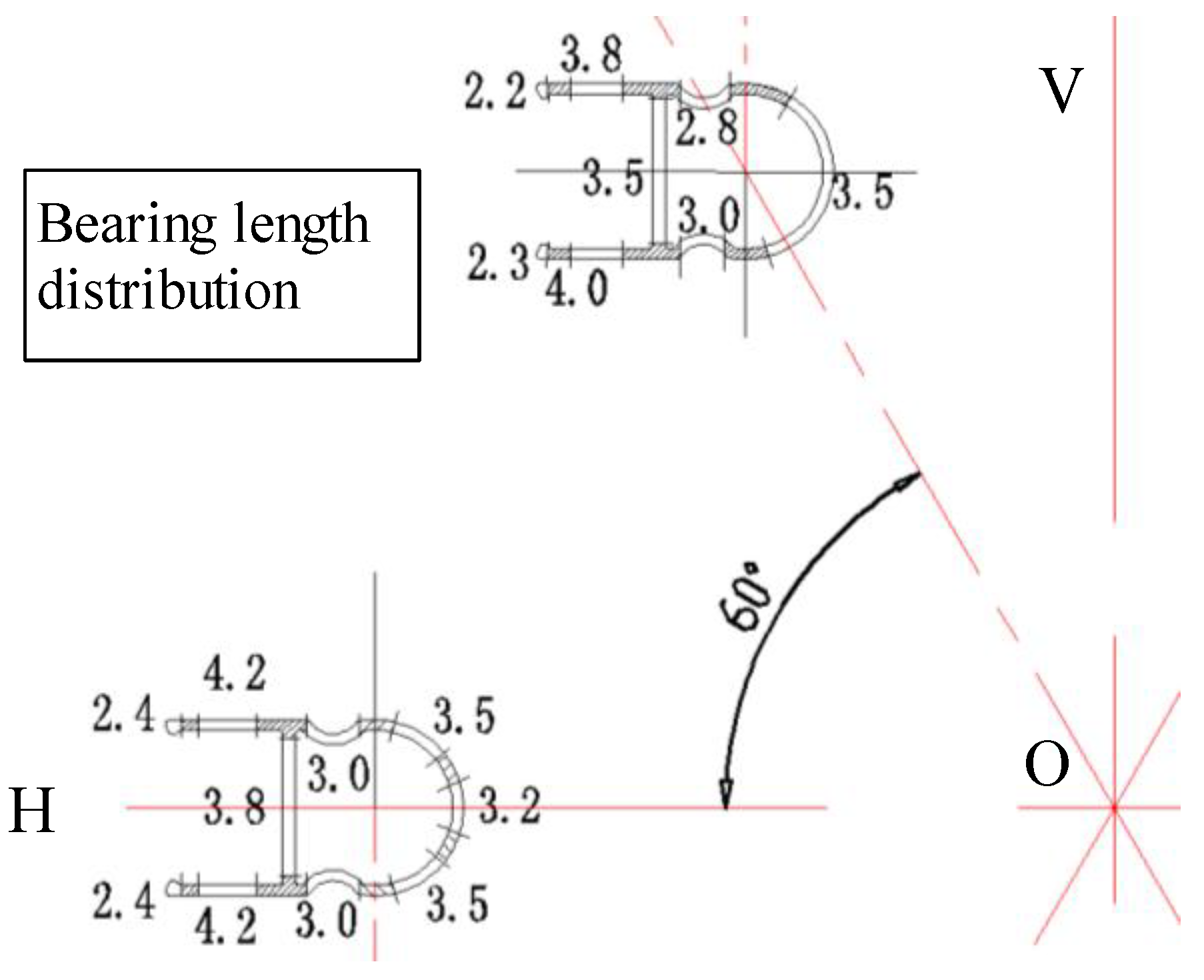
Figure 3 and Figure 4 show the main structures of the lower die with the two-step welding chamber and the non-uniform bearing length distribution, respectively. Both of design solutions have been proven to be effective in controlling the material flow compared to the previous or traditional design solution, as illustrated in Figure 5. It is reported that the forming load is reduced 10–12%. In this work, some key die features of the multi-output porthole extrusion will be assessed in terms of the material flow and the design scheme.
2.3. Design of Experiment by Means of the Taguchi Method
The Taguchi method has been employed widely in various fields in order to optimize die design or process parameters with a significant reduction in cost and time involved [21,22]. Besides the pocket contour in this studied case, there are several die features will affect the extrusion process or the metal flow balance, namely: the billet buckle angle (A), the porthole bevel angle (B), the depth of welding chamber (C), and the bridge type (D), as shown in Figure 6. The selected die feature parameters for the design of experiment (DOE) are given in Table 1. The experimental layout plan with four factors and three levels using L9 orthogonal array was performed to study the effects of the above mentioned die features on the metal flow during the multi-output porthole extrusion including the relative exit velocity of extruded profile and the mandrel deflection.
The Taguchi method determines the optimum values of each parameter using the SN ratio (Signal-to-Noise ratio). Generally, a larger signal and smaller noise is the best, so that the largest SN ratio yields the optimum result. The SN ratio is calculated according to the characteristics of the output properties, which are “the-smaller-the-better type”, “the-larger-the-better type”, and “on-target type”. Since the output properties of this research are the relative exit velocity of extruded profile and the mandrel deflection, “the smaller-the-better type” should be applied. The SN ratio of this type can be calculated as:
where n is the number of all the data points and yi is the ith value of the relative exit velocity of extruded profile and the mandrel deflection.
3. Thermo-Mechanical Modelling
3.1. Basic Theories of Numerical Algorithm and Material Model
The arbitrary Lagrangian Eulerian (ALE) algorithm has been adopted for the hot extrusion simulation of complex profiles [9,12]. This is because the ALE method is a combination of Lagrangian and the Eulerian approach, in which the mesh distortion and the difficulty of the free surface tracking can be effectively avoided. In the other word, the mesh in such a formulation can move arbitrarily, i.e., the mesh is not attached to the material particle like the Lagrangian method and not fixed in the space like the Eulerian approach as well. Thus, the computational mesh of the ALE algorithm can even move in one direction and be fixed in the other direction. The mass conservation law, momentum and energy equations can be expressed as follows:
For mass conservation law,
For momentum equation,
For energy equation,
where and are the density and the Lagranigain stress tensor respectively, and are the particle velocities in the referential coordinates, is the particle velocity in the spatial coordinates. is the body force per unit mass, and e is the internal energy per unit mass. The conservation equations for the mass, momentum and energy are necessary to be discretized and assembled into one system of the equations, which are calculated by using the iterative formulation.
In addition, a proper material constitutive relation is also important to describe the high-temperature deformation behavior of aluminum alloys. In this work, the typical Sellars-Tegart model is adopted to describe the extrusion deformation and yield the steady-state effective deviatoric flow stress as a function of parameters such as strain, strain rate, temperature, and so on [5]. It can be expressed as
where is the flow stress, n is a stress exponent, A is a constant, is the temperature-independent material parameter, and Z is the Zener-Hollomon parameter defined by
where is the effective strain rate, Q is the activation energy, R is the universal gas constant, and T is the absolute temperature (K). In this work, the aluminum alloy 6060 and the H13 steel are chosen as the deformable work-piece and the tool material, respectively. Aluminum alloy has been one of widely used materials because of its relatively light weight and satisfactory strength properties [23]. In the past decade, more than 80% of the manufactured extruded aluminum products are based on the AA6xxx series alloys due to their high extrudability [24]. In particularly, aluminum alloy AA6060 is the most widely used for the productions of the extruded thin-walled tubes in real applications. The strength of the alloy is dependent on many aspects such as the amount of Mg and Si in the solid solution, and the size and distribution of the Mg2Si precipitate particles. For a specific temperature, the flow stress of the studied AA6060 increases with the increase of strain rate. And for a fixed strain rate, the flow stress decreases apparently with the increase of temperature. The die material H13 steel with good abrasion resistance, hot hardness, and low sensitivity to heat checking can be subjected to drastic heating and cooling at a high process temperature. According to the above mentioned constitutive model, the corresponding material constitutive parameters of the studied AA6060 and the main physical properties of the H13 steel are listed in Table 2.
3.2. Process Modelling
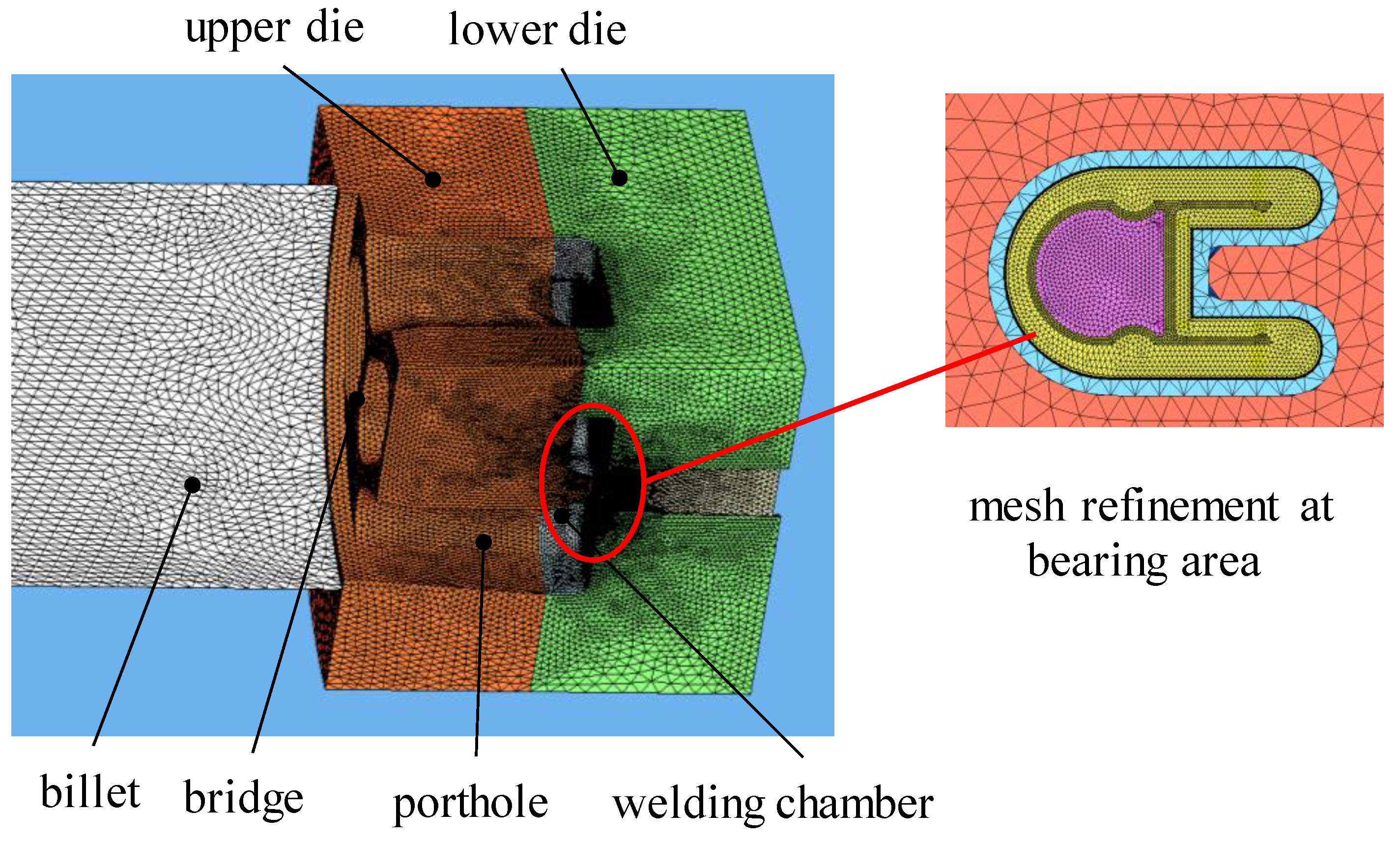
The finite element simulation of the multi-output porthole extrusion process is performed with the commercial code HyperXtrude (version 10.0) [25]. It is one of the products particularly for the extrusion manufactures from Altair Engineering Company (Troy, MI, USA). HyperXtrude is a virtual press where the user can visualize the material flow and the temperature inside a particular die during the extrusion processes. It makes the necessary changes to ensure the balanced flow and eliminate the product defects. The HyperXtrude can help to reduce the cost of the die-trials. The mesh element size has effects on the simulation accuracy and the computing time cost. Generally, the smaller mesh size implies a large amount of the elements and the higher prediction accuracy but the longer computing time. Due to the studied complex thin-walled profile with only 0.7 mm thickness, the mesh elements in the bearing area should be refined. Here, the triangular prism element is used in the part of the die bearing and the profile (see Figure 7), while the tetrahedral element is adopted in the other parts. In order to balance the computing time cost and the element number and calculation accuracy, a quarter of the geometric model is used for the simulations due to the symmetry. The varying mesh density with the whole model is carried out in accordance with the extent of local deformation. During the multi-output porthole extrusion, the areas close to the die bearing will undergo severe shear deformations because the final shape of the profile is formed in the die bearing. Thus, five layers of the elements in the regions of the bearing and the profile are assigned during the meshing stage. Meanwhile, the relatively coarse meshes are performed in the other regions. It should be noted that the each simulation work takes about 20–22 h to run for the studied extrusion process.
The initial billet used is 180 mm in diameter and 400 mm in length, and the extrusion ratio is up to 96.7. The initial temperature of the billet and the tools including dies and container are 480 °C and 430 °C, respectively. The extrusion ram speed is 5 mm/s. The heat convection and coefficient between the die and the billet material is 3000 W/m2·C as well as the work converted to heat of 90%. In order to simplify the complex interfacial conditions ranging from full sticking at the die entrance to slipping at the end of the bearing, an empirical friction factor of 0.3 is prescribed in the whole model. Because the profile extrusion processes usually involve a high contact pressure, it is generally more appropriate to use the law of constant plastic shear friction. A friction factor of 0.3 was prescribed to simplify the complex interfacial conditions. The extrusion process parameters used in the simulations are given in Table 3.
4. Results and Discussions
4.1. The Sources of Unbalanced Deformation
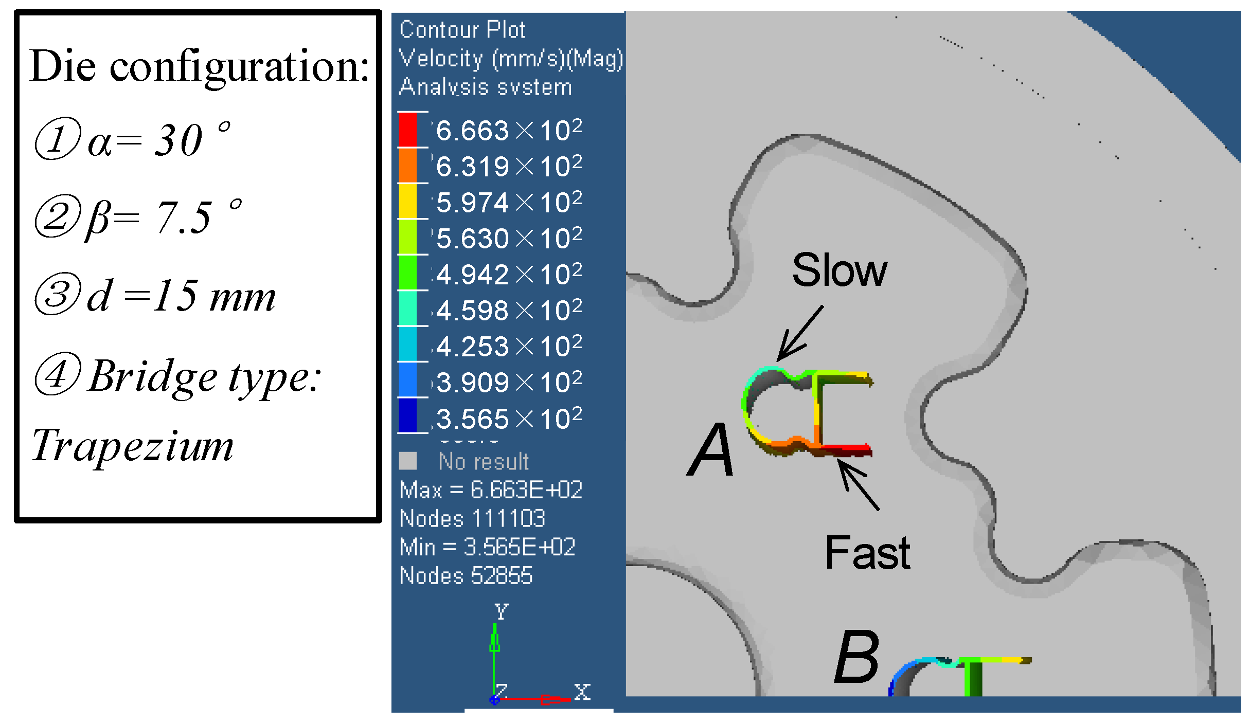
In order to explore the sources of unbalanced deformations of the aluminum alloy profile, two control strategies are proposed to obtain the optimal aluminum alloy extruded profile. Especially for the non-symmetrical profiles or even the multi-output porthole extrusion, it is more difficult to obtain the ideal shape profile after the hot extrusion processes. One of the sources of unbalanced deformation is the non-uniform relative exit velocity during the multi-output porthole extrusion process, as shown in Figure 8. It can be observed that the bearing length in the red areas should be increased to slow down the exit velocity. Thus, the bearing length in the blue area can be reduced to boost the exit material flow. In order to assure the dimension precision of the products and avoid various defects, such as twisting, bending, waving, cracks, etc., the outflow lengths (also known as bearing length or die land length) of the extrusion tools from each die orifice should be nearly identical. In the other word, all points in the cross section of the extruded profile should flow out of the die orifices with the same speed. Without such a uniform flow control, even simple profiles may not be extruded successfully. Of particular importance is the metal flow velocity at the die exit to judge whether this die will perform adequately in practice.
To describe the metal flow velocity distribution at the die exit, the standard deviation of the velocity field in the axial direction (SDV) is introduced as
The smaller value of the SDV, the better metal flow balance of the relative exit velocity or the extrusion quality. Therefore, the optimization of the bearing length and some key die features should be an efficient method to balance the exit material flow at the output side during the multi-output porthole extrusion process.
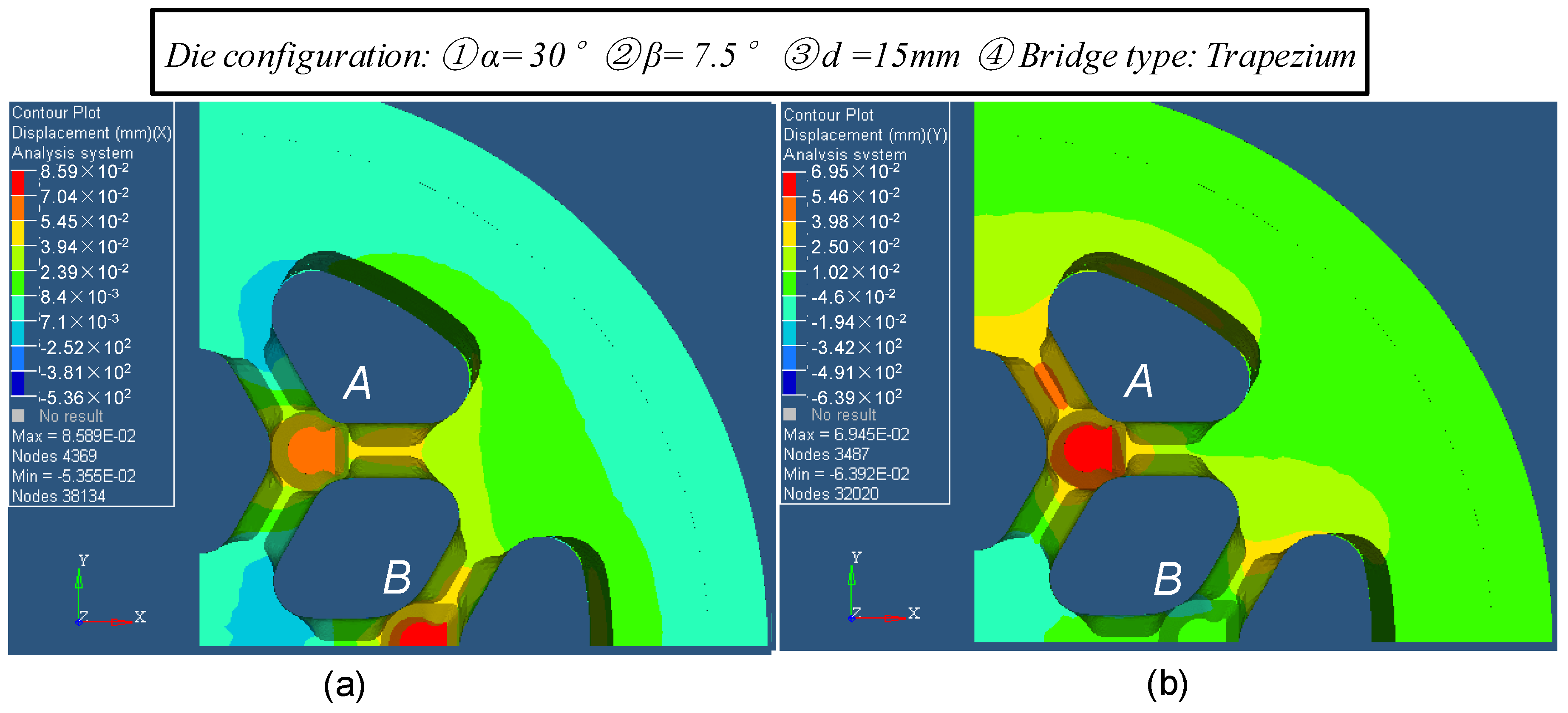
The other source is the mandrel deflection or the elastic deformation of the upper die during the multi-output extrusion process. Figure 9 shows the mandrel deflections of the upper die in one case of die configurations. The corresponding predicted maximum mandrel deflections (MMD) are listed in Table 4. The maximum wall thickness change of the extruded profile is up to 14% (0.0989/0.7). It is clear that the mandrel deflection should be considered at the design stage since it can cause a significant and undesirable wall thickness distribution of the final profile.
In practice, the efficient control of the mandrel deflection is still treated by the know-how experience and the “try and error” experiments. Meanwhile, the predicted results by analytical method deviate far from the experimental ones since the complicated multi-factor forming conditions are difficult to be considered in the formulas. Besides the experimental and analytical methods, the optimization design of the die structures including the bearing length, the pocket and the welding chamber integrated with accurate prediction by means of thermo-mechanical modeling can be an alternative control strategy for the multi-output porthole extrusion process.
4.2. Analysis of Variance
Three levels of each parameter were determined and arranged according to the L9 orthogonal table of the Taguchi method as shown in Table 5. Generally, 81 cases should be examined if three levels of four parameters were fully arranged. However, only nine cases were examined using the Taguchi method. The SN ratios of the four shape parameters are presented in Figure 10. The optimum values of the β were not the same in the two cases and the SN ratio varied significantly. This means that the β has the highest effect on the mandrel deflection and the relative exit velocity of the extruded profile.
Though the SN ratios indicated different values of α for the optimum value, the variation of α was very small. This means that the billet buckle angle has a slight effect on the mandrel deflection and/or the distortion of the extruded profile. It may be because the billet buckle angle α is far from the final extrusion process. Thus, we can choose any selected value of α for the optimum value. However, the billet buckle angle α in the upper die should play a considerable effect on the metal flow in the beginning of the multi-output extrusion process. For example, the flash overflow of material is prone to occur without the billet buckle angle α, as shown in Figure 11. The optimum value of the porthole bevel angle β has a significant effect on the mandrel deflection and the relative exit velocity in the multi-output porthole extrusion. The increase of the porthole bevel angle β decreases the mandrel deflection. However, the relative exit velocity decreases first and then increases with the increase of the porthole bevel angle β. The author attempts to explain that too large porthole bevel angle might cause the highlight of the direction change of the metal flow. Therefore, an appropriate porthole bevel angle is vital for the balance of the metal flow and the final profile distortion. The depth of the first welding chamber d seems to have effects but not very be obvious on the metal flow during the multi-output porthole extrusion. As for the effect of the bridge type, the trapezium of the bridge type seems to have the best chosen compared to the other types, because it can meet the demand the tool strength and the metal flow. The round type has the lowest of MMD because of the lower inlet bevel angle compared to the trapezium type. As for the brale type, the authors think the bridge strength is not strong enough for a high pressure extrusion.
Based on the above results, 30° of the billet buckle angle, 7.5° of the porthole bevel angle, and 15 mm of the depth of first welding chamber and the trapezium shape of the bridge type were determined as the optimum values for the mandrel deflection and the relative exit velocity, respectively. The maximum of the mandrel deflection at the location A and the relative exit velocity of the extruded profile having the optimum die feature parameters were predicted and validated experimentally.
4.3. Experimental Validation
The experiment equipment for the multi-output porthole extrusion process is a horizontal extrusion machine (maximum capacity 2000 Ton), namely SCHLOTMANN (NATIONAL MACHINERY EXCHANGE, INC., Newwark, NJ, USA). The main extrusion process parameters are listed in Table 3. The experimental observations of the upper die, the final extruded profiles and the distortion of the extruded profile are shown in Figure 12. It can be seen that the six-output extruded profiles have only a slight distortion at the head of extrusion and good surface quality. It is a successful industry application case for the presented multi-output porthole extrusion.
Figure 13 shows the comparison results of the wall thickness deviation along the section loci of the profile at the location A and the location B as previously shown in Figure 8, respectively. It can be seen that the predicted results at the location A are a little greater compared to the experimental ones. The maximum error occurred at the point 7 is about 0.012 mm. This may be due to the point 7 is the most far area to the center of the extrusion dies and has the largest moment of deformations. The other relative high errors occur at the point 8 for both of the location A and B, which are the area of middle wall or cantilever. This might be the serious contraction at the middle cantilever after the cooling of the extrusion process. This phenomenon has not been predicted by the adopted numerical model. In addition, the wall thickness deviation of the extruded profile at the location B is smaller than that at the location A. This may be due to that the profile at the horizontal location B has a less mandrel deflection compared to the location A. It also can be seen that the wall thickness distribution of the profile at the location B is almost symmetric to the horizontal center line.
The maximum extrusion pressure recorded at the experimental extrusion machine is 205 Ton larger than that predicted 191.7 Ton. The force deviation between the predicted result and the experimental one is about 6.93%. This is a relative high prediction accuracy and acceptable for an industrial extrusion case with a complex section.
5. Conclusions
In this paper, a typical industrial extruded aluminum alloy thin-walled profile with a snap-fit channel produced by the proposed multi-output porthole extrusion process was addressed. The design scheme of the multi-output porthole extrusion die was introduced as well as the development of its thermo-mechanical model. In order to explore the sources of the undesirable deformations and the unbalanced metal flow, the non-uniform relative exit velocity of the extruded profile and the mandrel deflection were analyzed based on the simulation model. Meanwhile, the optimization design of four key die structures was performed by using the Taguchi method. The main conclusions of this study are as follows.
- (1)
- The main structure design of the multi-output porthole extrusion die includes some novel features such as a circular pattern of the portholes with a dart-shape inlet bridge, a buckle angle in the inlet side of the upper die, a two-step welding chamber, and a non-uniform bearing length distribution. The presented die scheme is helpful to get a balance metal flow and reduce the forming load.
- (2)
- Four die structure parameters: The billet buckle angle, the porthole bevel angle, the depth of welding chamber, and the bridge type were optimized by the Taguchi method and optical simulation. Their optimum values are 30° of the billet buckle angle, 7.5° of the porthole bevel angle, 15 mm of the depth of first welding chamber, and the trapezium shape of bridge types, respectively.
- (3)
- The billet buckle angle α in the upper die should have a considerable effect on the metal flow in the beginning of the extrusion process rather than the metal flow control in the porthole stage. The porthole bevel angle β has significant effects on the mandrel deflection and the relative exit velocity in the multi-output porthole extrusion. The increase of the porthole bevel angle β decreases the mandrel deflection. The depth of first welding chamber d and the bridge type seem to have effects that may not be obvious on the metal flow during the multi-output porthole extrusion
- (4)
- In order to explore the sources of unbalanced deformations of aluminum alloy profile, two control strategies based on the simulation model, i.e., the optimal bearing length and the mandrel deflection compensation, are proposed to obtain a better metal flow and thin-walled aluminum alloy extruded profile.
- (5)
- The results of experimental validation show that the maximum wall thickness deviation has only 0.012 mm for the profile with a 0.7 mm of main wall thickness, and the force deviation between the predicted result and the experimental one is about 6.93%. This is a relative high prediction accuracy and acceptable for an industrial extrusion case with a complex section.
Author Contributions
X.X. and J.L. conceived and designed the multi-output porthole extrusion die; X.X., G.V., and A.B.P. performed the experiments; X.X., and J.P. analyzed the data; X.X., G.V., J.L., and A.B.P. contributed reagents/materials/analysis tools; X.X. and J.L. wrote the main paper.
Funding
The project supports from the Portuguese Foundation of Science and Technology (SFRH/BPD/114823/2016, UID/EMS/00481/2013, CENTRO-01-0145-FEDER-022083), National Natural Science Foundation of China (No. 51705080), the Natural Science Foundation of Fujian Province (No. 2018J01761; No. 2018J01764), Open test funding project for valuable instruments in Fuzhou University (2018T015) and the Fuzhou Science and Technology Project (2016-G-67).
Acknowledgments
The authors wish to thank Portugal industrial companies Bi-silque S.A. and Extrusal S.A. for the assistance of all the extrusion experiments and funding support.
Conflicts of Interest
The authors declare no conflict of interest.
References
- Berndt, N.; Frint, P.; Wagner, M.F.-X. Influence of Extrusion Temperature on the Aging Behavior and Mechanical Properties of an AA6060 Aluminum Alloy. Metals 2018, 8, 51. [Google Scholar] [CrossRef]
- Pan, J.Y.; Xue, X. Numerical investigation of an arc inlet structure extrusion die for large hollow sections. Int. Mater. Form. 2018, 11, 405–416. [Google Scholar] [CrossRef]
- Fan, X.; Chen, L.; Chen, G.; Zhao, G.; Zhang, C. Joining of 1060/6063 aluminum alloys based on porthole die extrusion process. J. Mater. Process. Technol. 2017, 250, 65–72. [Google Scholar] [CrossRef]
- Gagliardi, F.; Ambrogio, G.; Filice, L. On the die design in AA6082 porthole extrusion. CIRP Ann. Manuf. Technol. 2012, 61, 231–234. [Google Scholar] [CrossRef]
- Lof, J.; Blokhuis, Y. FEM simulations of the extrusion of complex thin-walled aluminum sections. J. Mater. Process. Technol. 2002, 122, 344–354. [Google Scholar] [CrossRef]
- Fang, G.; Zhou, J.; Duszczyk, J. FEM simulation of aluminum extrusion through two-hole multi-step pocket dies. J. Mater. Process. Technol. 2009, 209, 1891–1900. [Google Scholar] [CrossRef]
- Sinha, M.K.; Deb, S.; Das, R.; Dixit, U.S. Theoretical and experimental investigations on multi-hole extrusion process. Mater. Des. 2009, 30, 2386–2392. [Google Scholar] [CrossRef]
- Sinha, M.K.; Deb, S.; Dixit, U.S. Design of a multi-hole extrusion process. Mater. Des. 2009, 30, 330–334. [Google Scholar] [CrossRef]
- Zhang, C.; Zhao, G.; Chen, H.; Guan, Y.; Kou, F. Numerical simulation and metal flow analysis of hot extrusion process for a complex hollow aluminum profile. Int. J. Adv. Manuf. Technol. 2012, 60, 101–110. [Google Scholar] [CrossRef]
- Sun, Z.C.; Cao, J.; Wu, H.L.; Yin, Z.K. Inhomogeneous deformation law in forming of multi-cavity parts under complex loading path. J. Mater. Process. Technol. 2018, 254, 179–192. [Google Scholar] [CrossRef]
- Lee, J.M.; Kim, B.M.; Kang, C.G. Effects of chamber shapes of porthole die on elastic deformation and extrusion process in condenser tube extrusion. Mater. Des. 2005, 26, 327–336. [Google Scholar] [CrossRef]
- Zhang, C.; Zhao, G.; Chen, H.; Guan, Y.; Cai, H.; Gao, B. Investigation on Effects of Die Orifice Layout on Three-Hole Porthole Extrusion of Aluminum Alloy 6063 Tubes. J. Mater. Eng. Perform. 2013, 22, 1223–1232. [Google Scholar] [CrossRef]
- Gagliardi, F.; Ciancio, C.; Ambrogio, G. Optimization of porthole die extrusion by Grey-Taguchi relational analysis. Int. J. Adv. Manuf. Technol. 2018, 94, 719–728. [Google Scholar] [CrossRef]
- Bakker, A.J.D.; Werkhoven, R.J.; Sillekens, W.H.; Katgerman, L. The origin of weld seam defects related to metal flow in the hotextrusion of aluminum alloys EN AW-6060 and EN AW-6082. J. Mater. Process. Technol. 2014, 214, 2349–2358. [Google Scholar] [CrossRef]
- Bakker, A.J.D.; Katgerman, L.; Zwaag, V.D.S. Analysis of the structure and resulting mechanical properties of aluminum extrusions containing a charge weld interface. J. Mater. Process. Technol. 2016, 229, 9–21. [Google Scholar] [CrossRef]
- Zhang, C.; Dong, Y.; Wang, C.; Zhao, G.; Chen, L.; Sun, W. Evolution of transverse weld during porthole extrusion of AA7N01 hollow profile. J. Mater. Process. Technol. 2017, 248, 103–114. [Google Scholar] [CrossRef]
- Yu, J.; Zhao, G.; Cui, W.; Zhang, C.; Chen, L. Microstructural evolution and mechanical properties of welding seams in aluminum alloy profiles extruded by a porthole die under different billet heating temperatures and extrusion speeds. J. Mater. Process. Technol. 2017, 247, 214–222. [Google Scholar] [CrossRef]
- Gamberoni, A.; Donati, L.; Reggiani, B.; Haase, M.; Tomesani, L.; Tekkaya, A.E. Industrial Benchmark 2015: Process monitoring and analysis of hollow EN AW-6063 extruded profile. Mater. Today Proc. 2015, 2, 4714–4725. [Google Scholar] [CrossRef]
- Selvaggio, A.; Kloppenborg, T.; Schwane, M.; Hölker, R.; Jäger, A.; Donati, L.; Tomesani, L.; Tekkaya, A.E. Extrusion benchmark 2013—Experimental analysis of mandrel deflection, local temperature and pressure in extrusion dies. Key Eng. Mater. 2013, 585, 13–22. [Google Scholar] [CrossRef]
- Selvaggio, A.; Donati, L.; Reggiani, B.; Haase, M.; Dahnke, C.; Schwane, M.; Tomesani, L.; Tekkaya, A.E. Scientific Benchmark 2015: Effect of choking and bearing length on metal flow balancing in extrusion dies. Mater. Today Proc. 2015, 2, 4704–4713. [Google Scholar] [CrossRef]
- Chen, P.C.; Chen, Y.C.; Pan, C.W.; Li, K.M. Parameter Optimization of Micromilling Brass Mold Inserts for Microchannels with Taguchi Method. Int. J. Precis. Eng. Manuf. 2015, 16, 647–651. [Google Scholar] [CrossRef]
- Maheedhara, R.G.; Diwakar, R.V.; Satheesh, K.B. Experimental Investigation on radial ball bearing parameters ssing Taguchi Method. J. Appl. Comput. Mech. 2018, 6, 69–74. [Google Scholar]
- Esat, V.; Darendeliler, H.; Gokler, M.I. Finite element analysis of springback in bending of aluminum sheets. Mater. Des. 2002, 23, 223–229. [Google Scholar] [CrossRef]
- Cai, M.; Field, D.P.; Lorimer, G.W. A systematic comparison of static and dunamic aging of two Al-Mg-Si alloys. Mater. Sci. Eng. A 2004, 373, 64–71. [Google Scholar] [CrossRef]
- Altair Hyperworks, Material Database. Altair Engineering, Inc., 2018. Available online: https://altairhyperworks.com/ (accessed on 15 June 2018).
Figure 1.
(a) Geometry of thin-walled profile; (b) die configuration for multi-output porthole extrusion.
Figure 1.
(a) Geometry of thin-walled profile; (b) die configuration for multi-output porthole extrusion.

Figure 2.
The main structures of upper die.
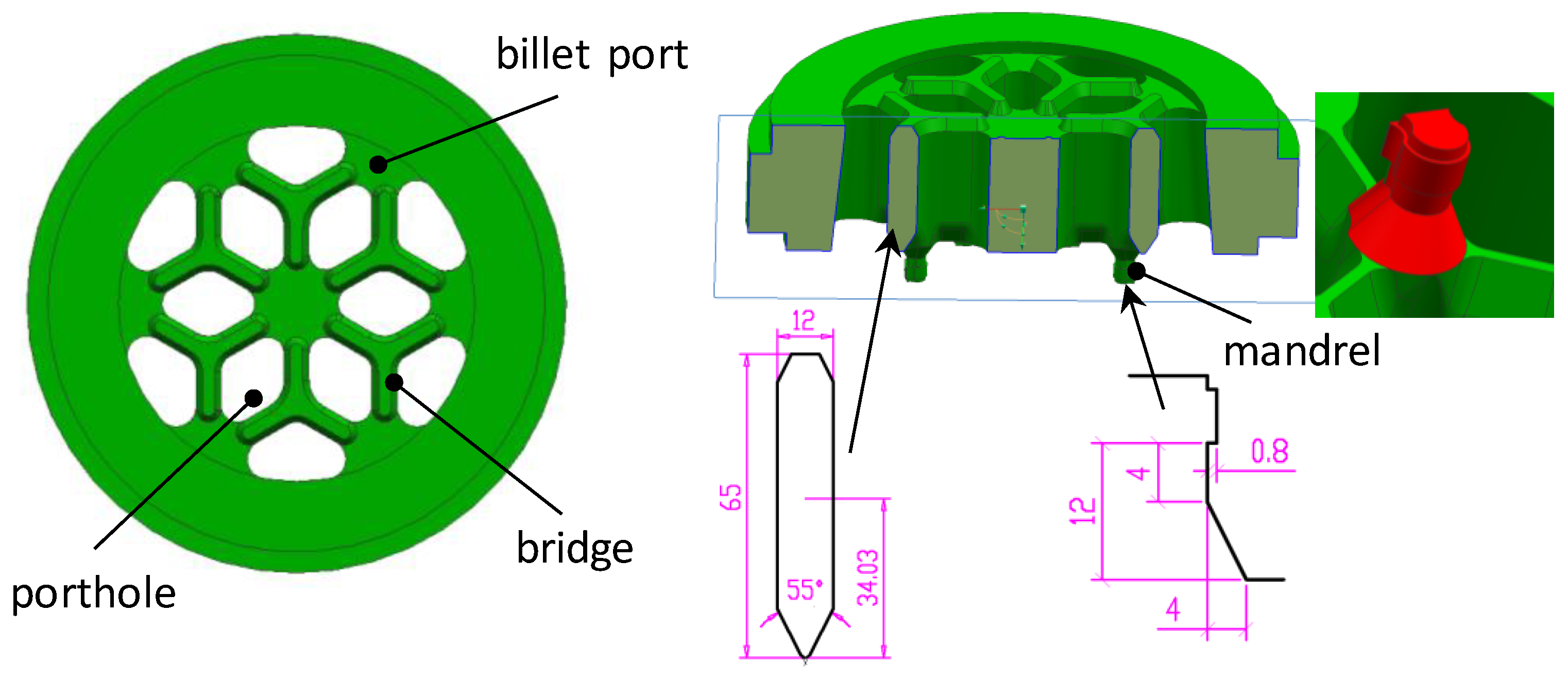
Figure 3.
The main structures of lower die.

Figure 4.
The non-uniform bearing length distribution of lower die.

Figure 5.
The traditional tool design in terms of the selected multi-porthole extrusion process.
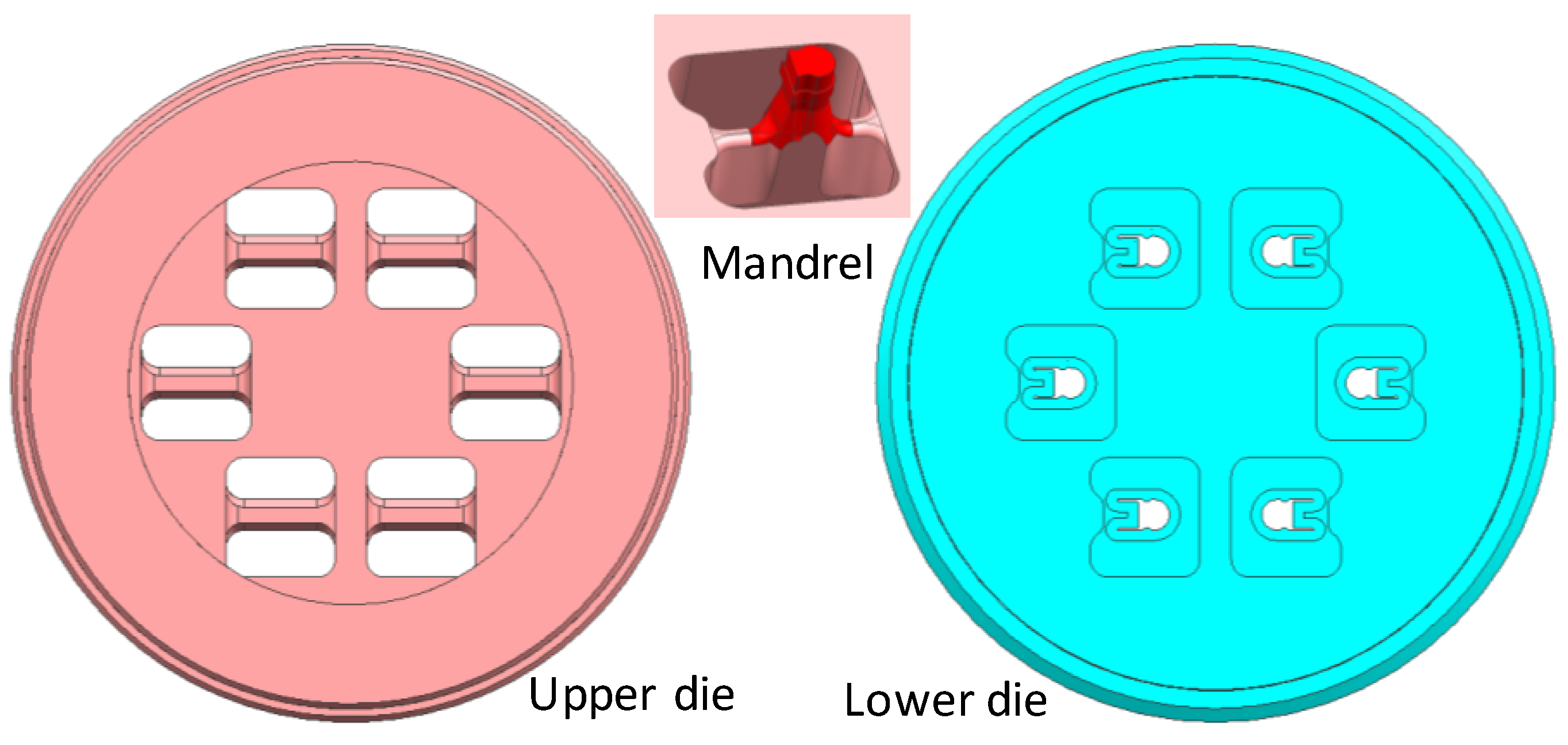
Figure 6.
The selected die feature for control factors of Taguchi method.
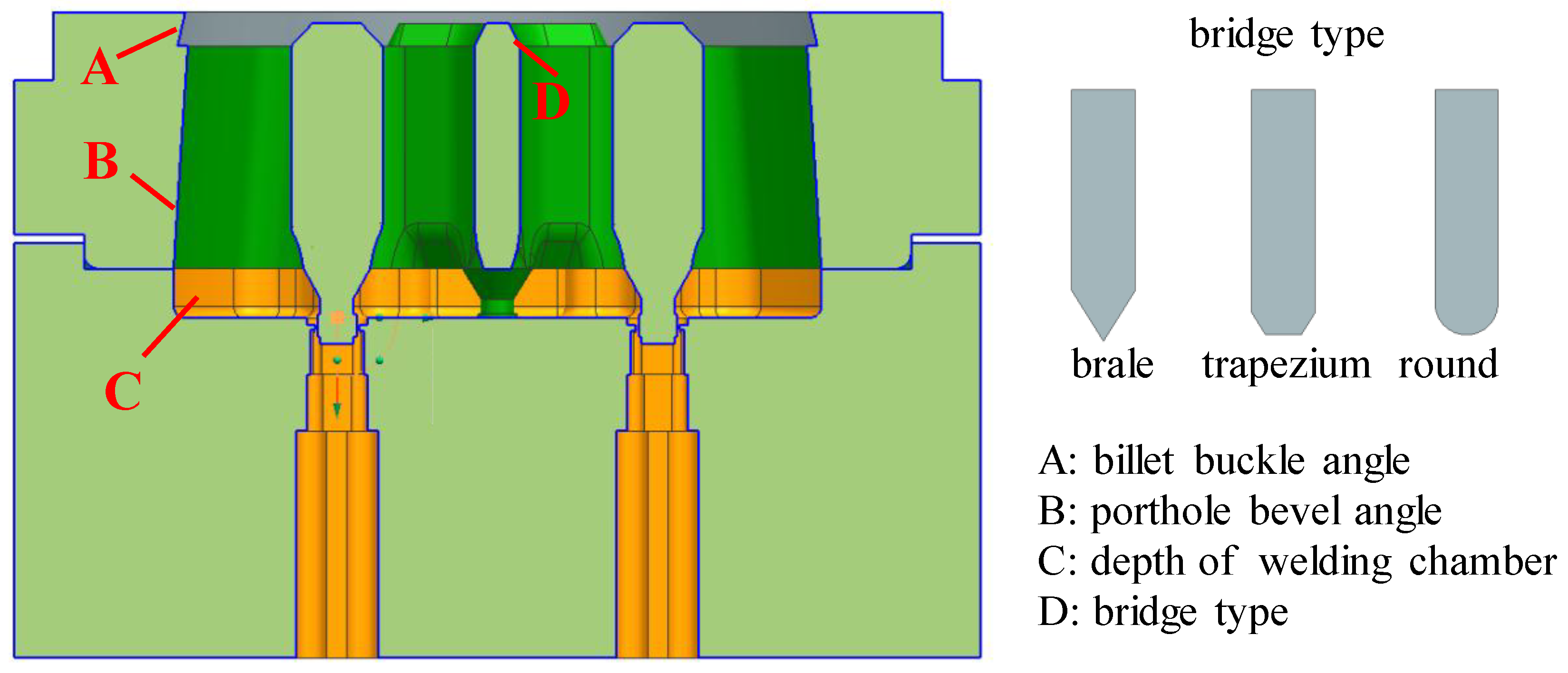
Figure 7.
Finite element modelling of the multi-output porthole extrusion.

Figure 8.
The distribution of the relative exit velocity.

Figure 9.
The mandrel deflections of the upper die: (a) X-displacement, (b) Y-displacement.

Figure 10.
The SN (Signal-to-Noise ratio) ratio values of four shape parameters for (a) MMD (maximum mandrel deflections) and (b) SDV (axial direction).
Figure 10.
The SN (Signal-to-Noise ratio) ratio values of four shape parameters for (a) MMD (maximum mandrel deflections) and (b) SDV (axial direction).
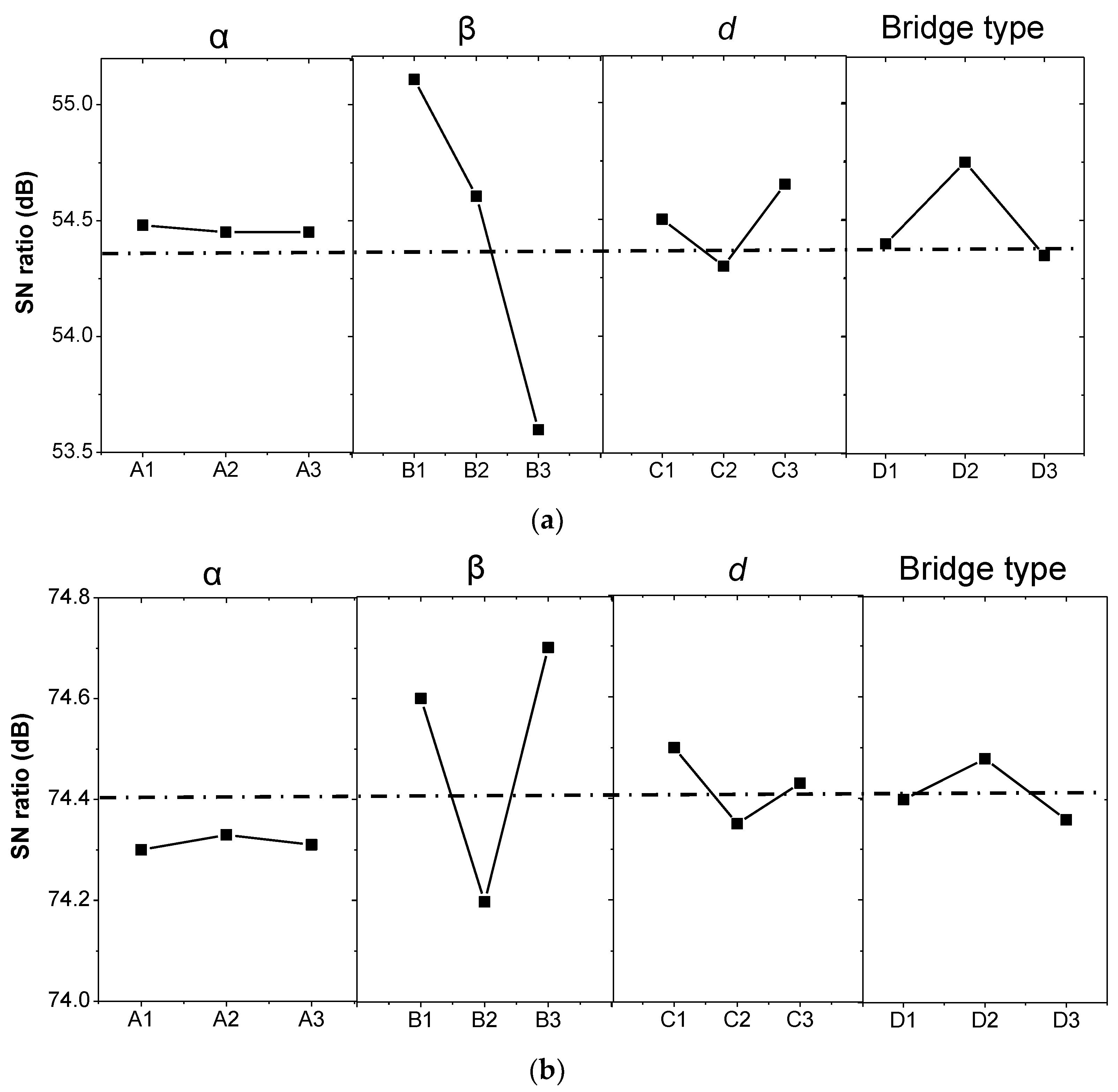
Figure 11.
The flash overflow of the material without billet buckle angle in the upper die.
Figure 12.
Experimental observations: (a) The upper die, (b) the extruded profiles, and (c) the nose end of the extruded profile with a slight shape distortion.
Figure 12.
Experimental observations: (a) The upper die, (b) the extruded profiles, and (c) the nose end of the extruded profile with a slight shape distortion.
Figure 13.
Comparison of wall thickness deviation between experimental and simulation results: (a) Location A and (b) Location B.
Figure 13.
Comparison of wall thickness deviation between experimental and simulation results: (a) Location A and (b) Location B.

Table 1.
Control factors and levels of die configurations used in the Taguchi method.
| Control Factors | Levels | |||
|---|---|---|---|---|
| 1 | 2 | 3 | ||
| A | Billet buckle angle (α, °) | 5 | 15 | 30 |
| B | Porthole bevel angle (β, °) | 5 | 7.5 | 10 |
| C | Depth of welding chamber (d, mm) | 10 | 15 | 20 |
| D | Bridge type | Brale | Trapezium | Round |
Table 2.
Material parameters of AA6060 and H13.
| Material | Q, J/mol | R, J/(mol·K) | A, s−1 | n | β, m2/N |
| AA6060 | 1.44 × 10⁵ | 8.314 | 5.91 × 10⁹ | 3.515 | 3.46 × 10⁻⁸ |
| Material | E, GPa | λ, N/(s·C) | ρ, kg/m3 | υ | δ, N/(mm2·C) |
| H13 | 210 | 24.3 | 7870 | 0.3 | 460 |
Table 3.
The process parameters of the multi-output porthole extrusion.
| No. | Process Parameters | Values |
|---|---|---|
| 1 | Billet diameter, mm | 180 |
| 2 | Billet length, mm | 400 |
| 3 | Extrusion ratio | 96.7 |
| 4 | Ram speed, mm/s | 5.0 |
| 5 | Billet preheat, °C | 480 |
| 6 | Container initial temperature, °C | 430 |
| 7 | Heat convection coefficient, W/m2·C | 3000 |
| 8 | Work converted to heat, % | 90 |
| 9 | Quantity of output | 6 |
Table 4.
The predicted mandrel deflections in one case of die configurations.
| Displacement Magnitude | MMD-A (mm) | MMD-B (mm) |
|---|---|---|
| X-displacement (max.) | 0.0703 | 0.0859 |
| Y-displacement (max.) | 0.0695 | 0 |
| XY-displacement (max.) | 0.0989 | 0.0859 |
Table 5.
The parameter conditions based on the L9 orthogonal array of the Taguchi method.
| No. | α (°) | β (°) | d (mm) | Bridge Type | MMD-A (mm) | SDV-A (mm/s) |
|---|---|---|---|---|---|---|
| 1 | 5 | 5 | 10 | Brale | 0.0989 | 10.256 |
| 2 | 15 | 7.5 | 15 | Trapezium | 0.0912 | 9.876 |
| 3 | 30 | 10 | 20 | Round | 0.0993 | 9.514 |
| 4 | 5 | 5 | 10 | Round | 0.0970 | 10.058 |
| 5 | 15 | 7.5 | 15 | Brale | 0.0905 | 9.879 |
| 6 | 30 | 10 | 20 | Trapezium | 0.1042 | 9.543 |
| 7 | 5 | 5 | 10 | Trapezium | 0.0992 | 10.119 |
| 8 | 15 | 7.5 | 15 | Round | 0.0918 | 9.894 |
| 9 | 30 | 10 | 20 | Brale | 0.1003 | 9.486 |
© 2018 by the authors. Licensee MDPI, Basel, Switzerland. This article is an open access article distributed under the terms and conditions of the Creative Commons Attribution (CC BY) license (http://creativecommons.org/licenses/by/4.0/).
Share and Cite
MDPI and ACS Style
Xue, X.; Vincze, G.; Pereira, A.B.; Pan, J.; Liao, J. Assessment of Metal Flow Balance in Multi-Output Porthole Hot Extrusion of AA6060 Thin-Walled Profile. Metals 2018, 8, 462. https://doi.org/10.3390/met8060462
AMA Style
Xue X, Vincze G, Pereira AB, Pan J, Liao J. Assessment of Metal Flow Balance in Multi-Output Porthole Hot Extrusion of AA6060 Thin-Walled Profile. Metals. 2018; 8(6):462. https://doi.org/10.3390/met8060462
Chicago/Turabian StyleXue, Xin, Gabriela Vincze, António B. Pereira, Jianyi Pan, and Juan Liao. 2018. "Assessment of Metal Flow Balance in Multi-Output Porthole Hot Extrusion of AA6060 Thin-Walled Profile" Metals 8, no. 6: 462. https://doi.org/10.3390/met8060462
Note that from the first issue of 2016, this journal uses article numbers instead of page numbers. See further details here.