Electrochemical Behavior of Biodegradable FeMnSi–MgCa Alloy
by
 ,
,
Nicanor Cimpoeşu
1, 
Florin Săndulache
1,
Bogdan Istrate
2 ,
,
Ramona Cimpoeşu
1,* and 
Georgeta Zegan
3 1
Department of Materials Science, Faculty of Material Science and Engineering, Technical University Gheorghe Asachi of Iași, Dimitrie Mangeron Street, No. 67, Iaşi 700050, Romania
2
Department of Mechanical Engineering Mechatronics and Robotics, Faculty of Mechanics, Technical University Gheorghe Asachi of Iași, Dimitrie Mangeron Street, No. 43, Iaşi 700050, Romania
3
Department of Surgery, Faculty of Dental Medicine, Grigore T. Popa University of Medicine and Pharmacy, Universitatii Street, No. 16, Iasi 700115, Romania
*
Author to whom correspondence should be addressed.
Metals 2018, 8(7), 541; https://doi.org/10.3390/met8070541
Submission received: 6 June 2018
/
Revised: 11 July 2018
/
Accepted: 11 July 2018
/
Published: 13 July 2018
Abstract
:Nowadays, alongside metallic biomaterials, there is increasing interest in using degradable metals in an appreciable number of medical applications. There are new kinds of metallic biomaterials for medical applications and many new findings have been reported over the past few years. Iron-based materials are a solution for biodegradable applications based on their mechanical and chemical properties. In order to control the corrosion rate of the Fe10Mn6Si alloy, we proposed the use of two additional elements, Ca and Mg, as corrosion promoters. The new material was obtained in an air-controlled atmosphere furnace after five melting operations. The material was in vitro analyzed from a corrosion resistance point of view. The experiments were realized by immersion (7, 14, and 30 days) in simulated body fluid (SBF) solution at 37 °C and a constant pH, and by electrochemical tests (electrochemical impedance spectroscopy (EIS), linear polarization (LP), cyclic polarization (CP)). Material surfaces before and after corrosion tests were analyzed through scanning electron microscopy (SEM), energy-dispersive X-ray spectroscopy (EDX), and X-ray diffraction (XRD) techniques. A discussion on the degradation rate of the material was realized from a comparison of the results. The results presented good composition homogeneity after the re-melting stages, with low percentages of Ca and Mg in the material, but with an adequate spread in the alloy.

1. Introduction
The accelerated development in the last few years of medical techniques of intervention in treating disorders in reparatory surgery or for implants has led to the necessary increase of materials with a role in replacing live tissues or in sustaining the healing processes of these lesions. Generally speaking, these materials are called biomaterials. Biomaterials are synthetic materials used to replace part of a live tissue or to function in deep connection with a live tissue. In a classic manner, the implants are permanent and have to achieve two qualities: to be inert (deprived of reactivity concerning other chemical elements or the environment of implantation) and to be resistant to corrosion [1]. Clinical studies realized have demonstrated that in the case of some illnesses or traumas, it is necessary to have just one temporary support for healing, support that can be assured only by implantable elements realized from biodegradable materials [2]. In this case, the degradation must start at a slow rate to maintain the optimal mechanical integrity of the implant until the process of re-modeling or healing is complete, and afterwards the process of degradation takes place quickly, without residues from the implant.
Consequently, the main component of biodegradable metallic alloys must be formed from metallic elements that can be metabolized by the human body (Mg, Fe, Zn, W, etc.) [3,4,5]. In medical applications, the concept of biodegradation is known in the form of biodegradable sutures. These materials come as an alternative to permanent implants (which in practice were observed to have long-term undesirable risks such as chronic inflammation, restenosis, or the incapacity of adapting to the shape of the blood vessels) [1,6]. At the same time, biodegradable materials can eliminate the interdiction of using these implants in the case of children. A major benefit for the patients, in the case of using implants from biodegradable materials in different medical applications, is the fact that at the end of the healing process of the disordered tissue, new surgery is not necessary to extract the implant. In this way, the results include the increasing comfort of the patient and reducing the medical costs.
Compared with Mg-based biodegradable materials, iron-based alloys present similar chemical, physical, and mechanical properties to stainless steel. Nevertheless, preliminary experimental tests have revealed a reduced degradation rate in both in vitro and in vivo conditions.
Alloying, the fastest processing process and heat treatment are the main approaches to modifying the mechanical, corrosion, and magnetic properties of pure Fe [2,6]. Based on microstructural, corrosion, and toxicological considerations, manganese is a suitable alloying element. Besides, manganese, calcium, and magnesium decrease the standard electrode potential of iron [6]. Furthermore, Mn, Si, Mg, and Ca are trace elements necessary in many diverse biological processes involving enzymatic processes.
The studies performed in the last decade recommend the use of these materials in a larger number of medical applications: osteosynthesis (prosthesis and elements of bonding the fractures like screws plates or intramedullary nails), coronary devices, devices for closing wounds, cardiovascular and tracheal stents, orthopedic, malleolar fractures, and aneurisms [7,8,9,10]. At present, the only clinical applications of biodegradable alloys are those based on magnesium (e.g., MAGNEZIX approved in 2013 for human patients) [10]. Iron-based alloys are an alternative to magnesium-based alloys for applications where a longer recovery period is required.
A new iron-based alloy, as a biodegradable alloy for medical applications, was analyzed in a biological environment by immersion and electrochemical corrosion evaluation. By adding Mg and Ca elements in the FeMnSi alloy, the authors worked to improve the corrosion characteristics of the alloy by providing a generalized corrosion of the metallic surface in contact with simulated body fluid (SBF) solution.
2. Materials and Methods
Using high-purity metallic elements Fe (Armco 99.99%), Mn (99.98%), Si (99.9%), Mg (99%), and master alloys like SiCa (60–40% wt), MgCa (85–15% wt), we obtained a new metallic material FeMnSi–MgCa. The obtaining process consists of two stages: first, melting the Fe, Mn, and Si elements in an electric arc furnace (RAV MRF ABJ_900, Allenstown, NY, USA), and second, the addition of Mg and Ca elements using a vacuum induction furnace (UltraCast, Ronkonkoma, NY, USA) in a ceramic crucible. Calculations, taking in account the loss at high temperature, were made to obtain Fe10Mn6Si and additions of Mg and Ca within 1 wt%. The melting points of calcium (842 °C) and magnesium (650 °C) are very low in comparison to that of iron (1538 °C) and manganese (1246 °C). Due to the major difference between melting points, problems appear in achieving a homogenous solid solution of the nominal composition. After finishing the process of melting, the caster is removed from the furnace and the material cooled to room temperature. To obtain the homogenization, four re-meltings were performed, followed by the annealing of homogenization in a fluid bed (in sand) at 1050 °C for 300 min, the cooling being made simultaneously with the sand in which it was heated. This heat treatment plays an important role in reducing the heating fragility during the hot deformation process [11].
Immersion tests were realized in a temperature-controlled enclosure box (37 °C) for three similar samples in a re-circulated simulated body fluid solution with the chemical composition (presented in Table 1) and with a daily control of pH (approximately 7.5) [12].
The heating system of the experimental samples was provided with the possibility of turning at 180°, and the operation was realized daily to expose the whole metallic surface to the SBF solution. For immersion, the samples were abraded (with abrasion papers of SiC up to 2000 grit) and the surface was cleaned in an ultrasound bath (30 min) in industrial alcohol. The samples were immersed for 7, 14, and 30 days. Additionally, the samples were weighed before and after the immersion with a micro-analytical balance scale (Premier −4 decimals). The products of corrosion unlinked to the biodegradable metallic materials based on Fe could be removed through the immersion in a solution (20 g of Sb2O3 and 50 g of tin chloride were dissolved in 1000 mL of hydrochloric acid and sonication for 30 min [2,13]).
Electrochemical measurements were performed using a Dynamic Electrochemical System VoltaLab 40 (PGZ301) (Radiometer Analytical SAS, Lyon, France) on three samples for the experimental material in SBF at 37 ± 1 °C. The experimental set-up was made in a three-electrode cell connected with potentiostat equipment with the alloy sample (ground up to 2000 grit) with a rotating working electrode (50 rpm), a saturated calomel electrode (SCE) as the reference electrode, and a platinum wire as the counter electrode. The tests were repeated three times to achieve proper repeatability of the results.
Working cylinder electrodes were mounted in a Teflon support to enable the connection to the rotating electrode of electrochemical system. A 0.25–0.30 cm2 cross area of the working electrode was used.
The testing conditions used for the experimental tests to perform the electrochemical measurement were as follows: linear polarization: range (–200)–(+200) mV vs. free; scanning rate = dE/dt = 0.5 mV/s; cyclic polarization: potential range (−800, 2000 mV); scanning rate = 10 mV/s; electrochemical impedance spectroscopy (EIS) measurements: Work potential—free; frequency range = 105–10−2 Hz; AC amplitude = 10 mV; open circuit potential (OCP): 15–30 min vs. free; resolution time = 0.2 s. All potentials were measured versus the saturated calomel electrode. The sequence of experimental measurements was: OCP → EIS → linear voltammetry → OCP → cyclic voltammetry.
The acquisition and processing of the electrochemical data were achieved with the VoltaMaster 4 software (Radiometer Analytical, Lyon, France). The EIS data purchased with the VoltaMaster software were processed with ZSimpWin software (Princenton Applied Research, Farnborough, Hampshire, UK,) where the electrochemical spectra were interpreted by the least square method developed by Boukamp. For this purpose, the VoltaMaster data were converted to Z date with the EIS file converter (Radiometer Analytical S.A. Lyon, France).
The chemical composition details were obtained using energy-dispersive X-ray spectroscopy (EDX) Esprit software PB-ZAF with automatic and element list analyze modes detector from Bruker connected to scanning electron microscope (SEM) equipment-VegaTescan LMH II (30 kV, SE detector, high vacuum). Standard deviations were provided for all chemical determinations. The material surface was analyzed through X-ray diffraction (XRD) analysis using X’Pert equipment (20:20–90).
3. Results and Discussion
The experimental results presented preliminary information on the degradation rate of the new alloy. Through microscopy, the state of the surface before and after the tests of corrosion resistance was highlighted through immersion and linear and cyclic potentiometry. Through chemical analysis, the chemical compounds formed on the surface were determined and were followed by the chemical evolution of the alloy at the interface with the biological solution/electrolyte solution.
3.1. Surface Characterization
The surface state of the alloy FeMnSi–MgCa is presented in Figure 1, for the initial state and after immersion in SBF (at 37 °C) for 7, 14, or 30 days. The 2D and 3D images present corrosion (a corrosion pitting type quite agglomerated with the unification of the holes in most cases) with different aspects depending of the immersion period. The sizes of the pitting “holes” were of a micrometer scale for diameter/length/width and depth.
The surface of the sample maintained for 14 days presented the biggest tracks of corrosion and the presence of compounds with good stability on the material.
Immediately after immersion in the experimental solution, the alloy was oxidized to metal ions following reactions (1)–(4). The compounds formed on the surface after immersion were based on the alloy main elements, especially oxides. Anodic reactions were based on the component elements of the alloy.
Fe → Fe2+ + 2e−
Mn → Mn2+ + 2e−
Mg → Mg2+ + 2e−
Ca → Ca2+ + 2e−
The electrons from the anodic reaction were consumed by a corresponding cathodic reaction and the reduction of oxygen dissolved in water (reaction (5)).
2H2O + 2e− → H2 + 2OH−
Product formation on the material surface are based on reactions (6)–(10):
2Fe2+ + 4OH− → 2Fe(OH)2 or 2FeO·2H2O
4Fe(OH)2 + O2 + 2H2O → 4Fe(OH)3 or 2Fe2O3·6H2O
Mn2+ + 2H2O ↔ MnO2 + 4H+ + 2e−
Si + 2H2O ↔ SiO2 + 2H2
Si + 4OH− ↔ SiO44− + 2H2
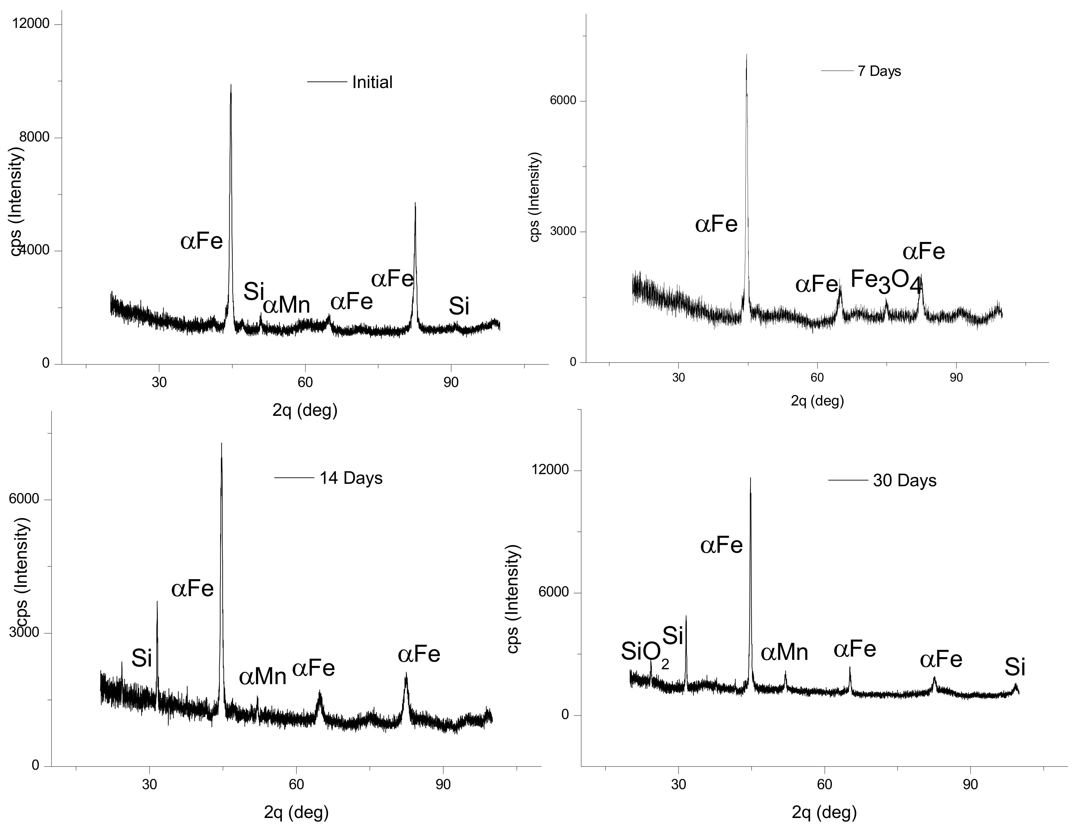
The corrosion by the oxidation surface layer of iron alloys is usually based on FeO·nH2O, Fe3O4·nH2O and Fe2O3·nH2O [14]. The XRD analysis detected magnetite Fe3O4 and SiO2 weak peaks alongside the peaks of the main elements.
The presence of the reaction compounds from the interaction between the metallic material and the immersion solution (SBF) was observed as well as in the case of the sample maintained in liquid for 30 days. In this interval, many interactions of the metallic material took place with the solution and different compounds were formed on the surface. In the case of the immersion for seven days, a deep corrosion of the surface (microns order) was observed. 3D images of the surface showed the presence of compounds with small sizes. This resulted from the reaction compounds on the surface growing and agglomerating during the immersion period.
After a seven-day immersion period, an area affected by corrosion was observed at a proportion of 50%, and this surface grew gradually for 14 and 30 days, where the whole surface was corroded or covered the reaction compounds.
3.2. Surface Chemical Characterization
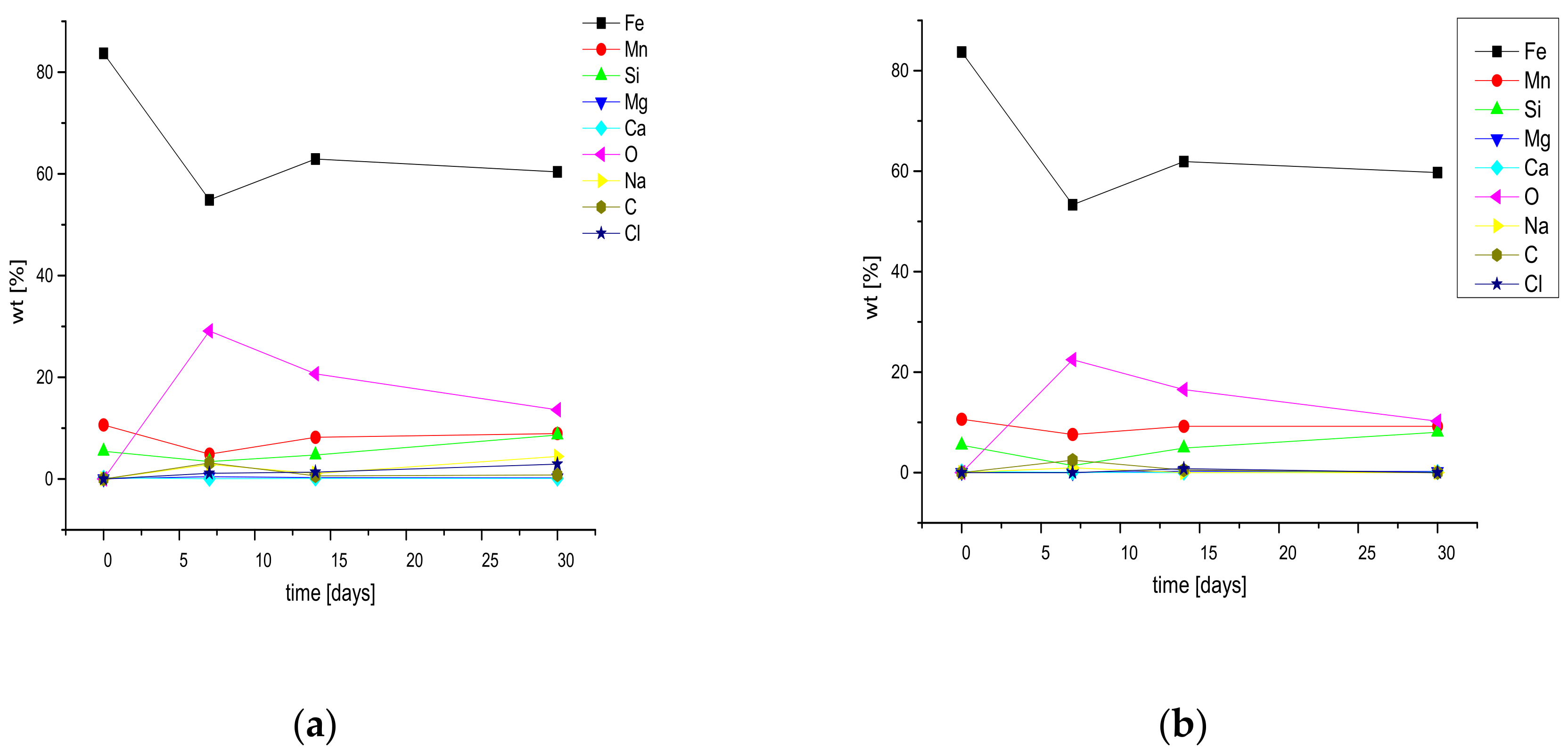
The experimental material surface was analyzed using the EDX technique to observe the evolution of the chemical element percentages after the immersion periods. The initial composition of the alloy is Fe 83.17, Mn 10.9, Si 5.44, Mg 0.6, Ca 0.20.
Chemical determinations were made before and after a sonication cleaning treatment. In Figure 2, the distributions of the elements Fe, Mn, Si, Mg, Ca characteristic of the immersed alloy and the distributions of the elements Na, Cl, O, and C that were identified through qualitative EDX analysis of the surface are presented. Daeho et al. [15] suggested that the phase precipitated along the grain boundaries was Mg2Ca after studying the microstructures of a binary Mg–Ca alloy. In our case, we also expected to have precipitates in the microstructure. For the sample immersed for seven days, traces of oxides on the surface, especially on the left side of the analyzed surface, were observed on the surface (Figure 2a), as was the presence of chlorine and sodium on the surface under the form of zonal compounds. From the pitting corroded areas, we observed a decrease of the signal for the elements Fe, Ca, and Mg. For the sample immersed for 14 days, we also observed an area of the alloy affected by corrosion, a zonal distribution of the compounds based on chlorine that coincided in some areas with those of sodium, possibly due to the formation of salts on the surface of the metallic material. In the last case, the sample immersed for 30 days, a corroded and oxidized surface could be seen with a larger number of chlorine compounds that appeared in the form of unstable, chemical formations on the surface of the alloy. On the surface of the sample immersed for 30 days, the appearance of the compound silica (SiO2) was identified and further confirmed through XRD analysis. In the case of the sample immersed for 30 days, most of the corroded surface was covered by compounds resulting from the interaction with SBF solution. These compounds appeared as a result of the oxidation of the base elements of the alloy or after the deposition of compounds from the solution on the surface.
To determine the stability of the compounds that appeared on the surface of the metallic material in the immersion period (with a very important role in the determination of the degradation characteristics of the alloy), the samples underwent a cleaning procedure. The chemical compositions of the surfaces after the cleaning stage with ultrasonication are presented in Table 2 (mass percentages and atomic percentages of the elements identified on the surface as well as the typical error of the EDX detector for each chemical element).
From Figure 3, in the case of the immersed sample for seven days, we observed the formation on the surface of Fe, Mn, and Si oxides as well as the appearance on the surface of salts that confirmed the analysis through the distribution of the elements presented previously.
After the ultrasonic cleaning (USC) stage (all the results are characterized by the following standard deviations: Fe: ±1.1; Mn: ±0.22; Si: ±0.3; Mg: ±0.1; Ca: ±0.05), we observed the separation of large quantities of silica oxides and some Fe and Mn oxides. We also observed a total removal of the salts from the surface following the cleaning stage. The alloying elements Mg and Ca did not appear any further, or were in very small quantities (0.05 wt% Ca) after cleaning the surface. This confirmed the role of these elements in increasing the degradation rate of the experimental alloy as well as in the smoothing of corrosion on the entire surface. After 14 days of immersion, we identified smaller amounts of oxides on the surface in comparison with the results on the immersed sample for seven days, affirming the validation for all of the Fe, Mn or Si oxides.
The percentages of Mn and Si after the cleaning stage were close to the initial values, a fact that signified an almost total transfer of the oxides of these elements in the immersion solution. Furthermore, after 14 days of immersion in SBF, Na salts and carbon-based compounds appeared on the surface (possible carbonates of MgCO3 or CaCO3 [2], that passed into the solution after the ultrasonic cleaning stage). There was also the possibility of the formation of some calcium carbonates from the experimental alloy that were not removed through the cleaning stage, a fact that explains the high percentage of mass of Ca and the presence of C on the surface after the cleaning operation.
After 30 days of immersion, the surface presented the lowest amount of oxides, mainly based on Fe and Si, and a larger amount of salts in comparison with the surfaces of the samples immersed for seven and 14 days. After cleaning, there were no more salts or carbon-based compounds. This confirmed the presence of a higher quantity of Si (observed in the distribution from Figure 2c), a fact that can be explained through the kinetics of the formation of Si oxides and also through the passing rates of Fe, Mn, and Si of these compounds in solution. After this immersion period, there was the first case where on the surface, after ultrasonic cleaning, also appeared the elements of Mg and Ca, pertaining mostly to the experimental alloy.
Figure 4 presents the characteristic XRD graph of the surface of both the initial sample and the surface of the metallic samples after immersion in SBF. In the initial state, the alloy was characterized by peaks of alpha–ferrite that represented the main phase of the pure iron. Two peaks characteristic of Si and Mn compounds were also identified. For the samples maintained in SBF for seven and 30 days, the XRD spectra identified characteristic peaks for the oxides Fe3O4 and SiO2 [13].
Analyzing the XRD graph of the experimental alloy, there were no characteristic peaks of pure Ca or Mg in the X-ray diffraction pattern (Figure 4). One reason for this could be that the weight percent of Ca or Mg considered in this study was lower than 1 wt%, which could influence below the detection limit of standard X-ray diffraction units. The shift in the peak position, in comparison with the literature [14], is indicated in the lattice parameter, reflecting the incorporation of these two elements into the Fe–Mn lattice as also presumed from the EDX results.
Table 2 presents the main characteristics of the experimental samples used in the immersion test (length, width, and height of the samples) as well as the values of their weights before and after the periods of immersion and after cleaning the surfaces through sonication. The total area was calculated by taking into account all six areas exposed to the SBF solution. In the case of the immersion test for the calculus of corrosion rate (CR), some parameters are necessary (the mass of the samples before and after immersion, the surfaces of the samples, or the density of the experimental material). During the test, we determined both the loss of weight and the quantity of metallic ions freed in the solution (this solution will be approached in a future article). The corrosion rate of the biodegradable metallic materials can be calculated using Equation (11) [2]:
where CR refers to the corrosion rate; W is the loss of mass calculated of the sample from biodegradable metallic material; A is the surface exposed at corrosion; t is the time of immersion; and ρ′ is the standard density of the alloy (in this case, the alloy had an experimental value of 6.122 g/cm3). Using the data from Table 2, we obtained the following values for the corrosion rate: after seven days of immersion it was 491.015 µm/year; after 14 days of immersion it was 355.463 µm/year; and was 211.018 µm/year after 30 days of immersion (the average rate of degradation is of 352.50 µm/year). Taking into account the differences of mass that appeared after the immersion of the experimental samples for 7, 14, and 30 days, a degradation rate of 0.204 µm/year was obtained through the linear fitting of the results by calculating the descent of the slope.
Applying Equation (1) to the experimental data obtained after sonication cleaning of the surface (Table 2), we determined the corrosion rate of the alloys that attended to the removal of the non-adherent compounds on the material surface. The values obtained were as follows: after seven days of immersion it was 768.294 µm/year; after 14 days of immersion it was 767.800 µm/year; and it was 308.99 µm/year after 30 days of immersion. The average rate of degradation was 615.028 µm/year.
3.3. Surface Electrochemical Characterization
Potentiodynamic polarization and the impedance measurements were the methods used to determine the corrosion rate of the biodegradable metallic materials. The density of the corrosion current icorr can be estimated from the analysis of the linear curve (Tafel) and can also be determined from the polarization resistance obtained from the impedance measurements using the Stern–Geary equation [16]. The corrosion rate can be calculated with Equation (12):
where CR refers to the degradation rate, k1 = 3.27 × 10⁻³ mm∙g∙µA−1∙cm−1∙; icorr is the density of the corrosion current; ρ is the density of the metallic material (in this case the alloy has the experimental value of 6.122 g/cm3); and W and n refer to the atomic mass of the main element Fe and its valence, respectively.
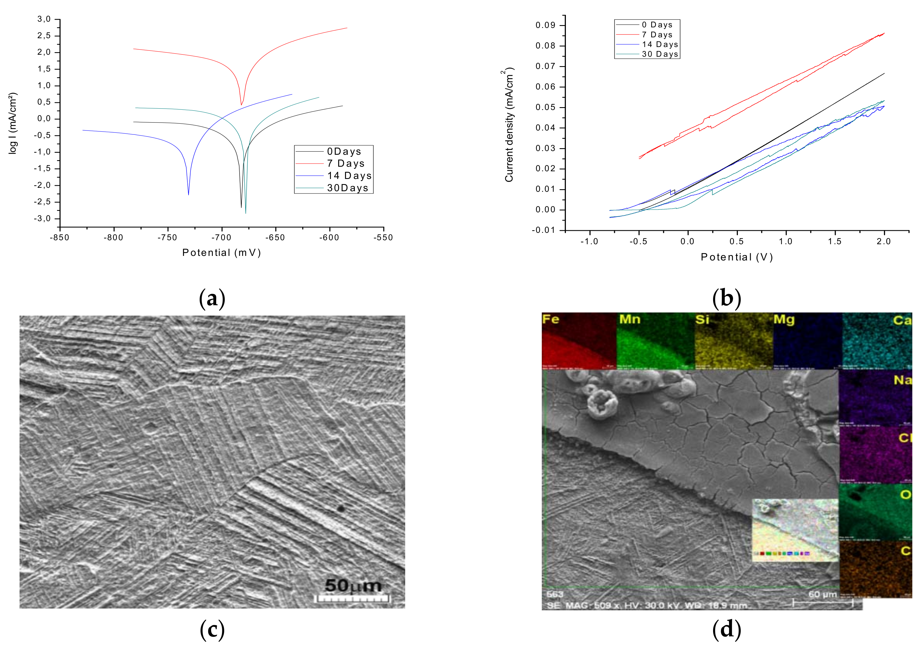
Figure 5a shows representative Tafel curves obtained from the potentiodynamic linear polarization of the experimental alloy measured in SBF solution.
Upon anodic polarization, the Fe–Mn–Si + (MgCa) alloy shows, similar to Fe–1C, an active dissolution behavior, whereby in the low polarization regime up to about −0.3 V, the slope of the curves is steeper than that in the Fe–1C [17] curve, revealing higher dissolution rates. Consequently, the mass-transport controlled dissolution reflected by the current plateau is reached much earlier. The effect of adding Ca and Mg was assessed by the potentiodynamic polarization test where the results showed an increased corrosion current density related to the amount of Ca and Mg present in the solid solution [18,19]. The corrosion current density (jcorr) is representative of the degradation degree of the alloy. It is evident from Figure 6 and Table 3 that, first, there was a decrease of corrosion current density after seven days which was associated with the formation of a thin oxide layer on the metallic surface, followed by a high increase of the current after 14 and 30 days. In comparison with FeMnSi alloy behavior, we had a jcorr value approximately 12 times larger (695/59 µA/cm2) [19]. Part of the difference could be attributed to the addition of small quantities of Mg and Ca.
The lower values of the anode Tafel slope indicated that anodic oxidation was active while the higher values of the cathode Tafel slope indicated that the reduction processes (either hydrogen: 2H+ + 2e− → H2 or water: H2O + 2e− → H2 + 2HO− or other ionic species in the solution) were controlled by` concentration and controlled the global corrosion process. Large differences between the cathode slopes could be attributed to the complexity of the reduction processes as well as the formation of the films on the surface of the alloy maintained in solution.
The electrochemical corrosion test performed in the SBF solution revealed medium-size grains [19,20] and a surface preferentially corroded based on the grain plate’s orientation (Figure 5c). Small areas were covered with oxides and salts (Figure 5d) that formed a new layer of corrosion on top of the alloy’s surface.
In quantitative terms, the corrosion potentials for the four samples were negative and quite large, ranging between −727 and −667.9 mV/ESC, placing this alloy in the category of being easily corrodible in SBF. The open circuit potential was greater than the potential for corrosion in all cases. This could be explained by the fact that while OCP is measured at a zero corrosion rate (at metal–solution equilibrium), Ecor (corrosion potential) is measured under dynamic conditions; by continuously altering the alloy potential, the surface reaction is more or less away from equilibrium. The higher the scanning rate of the potential, the more the reaction was farther away from the equilibrium and the Ecor deviated more from the OCP value [21].
Qualitatively, the thermodynamic tendency of corrosion of the alloy was greater when the surface of the alloy was freshly polished and decreased when the alloy remained in longer contact with the corrosion medium. From the point of view of the corrosion rate, it was observed that maintaining a relatively reduced time (seven days) in the solution led to passivation of the alloy; the corrosion rate dropped approximately 12 times. This may be due to the fact that by contacting the alloy with the solution, a slow corrosion process takes place, forming a compact (black) coating that protects the surface and leads to increased polarization resistances (Rp) and to the reduction of the cathodic current, which is controlled by diffusion (beta cathodic (bc) << beta anodic (ba)). Instead, maintaining a longer time (14 days) of the alloy in the solution led to much higher corrosion rates, even in the case of the newly mechanically polished surface. This may be due to the fact that with the increase in the thickness of the product layer, there are crevices through which the corrosion medium penetrates into the alloy.
The cyclic polarization curves for the FeMnSi–MgCa sample in SBF, recorded in the four cases (maintained 0 days, 7, 14, and 30 days in solution), are presented in Figure 5b. All curves were typical of generalized corrosion; the cathode branch perfectly overlapped the anodic branch. All curves were linear over the entire range of potential used; the current density, and as a result the corrosion rate, was increased directly to the overvoltage applied to the electrode.
The corrosion current density values are particularly high, suggesting advanced alloy corrosion in the SBF solution. In this case the smallest corrosion is encountered in the case of the alloy immersed for 7 days in the solution and the highest for the alloy maintained for 14 days in the solution. It can be observed that the corrosion process starts from potential (−0.5 V) and increases significantly with over potential.
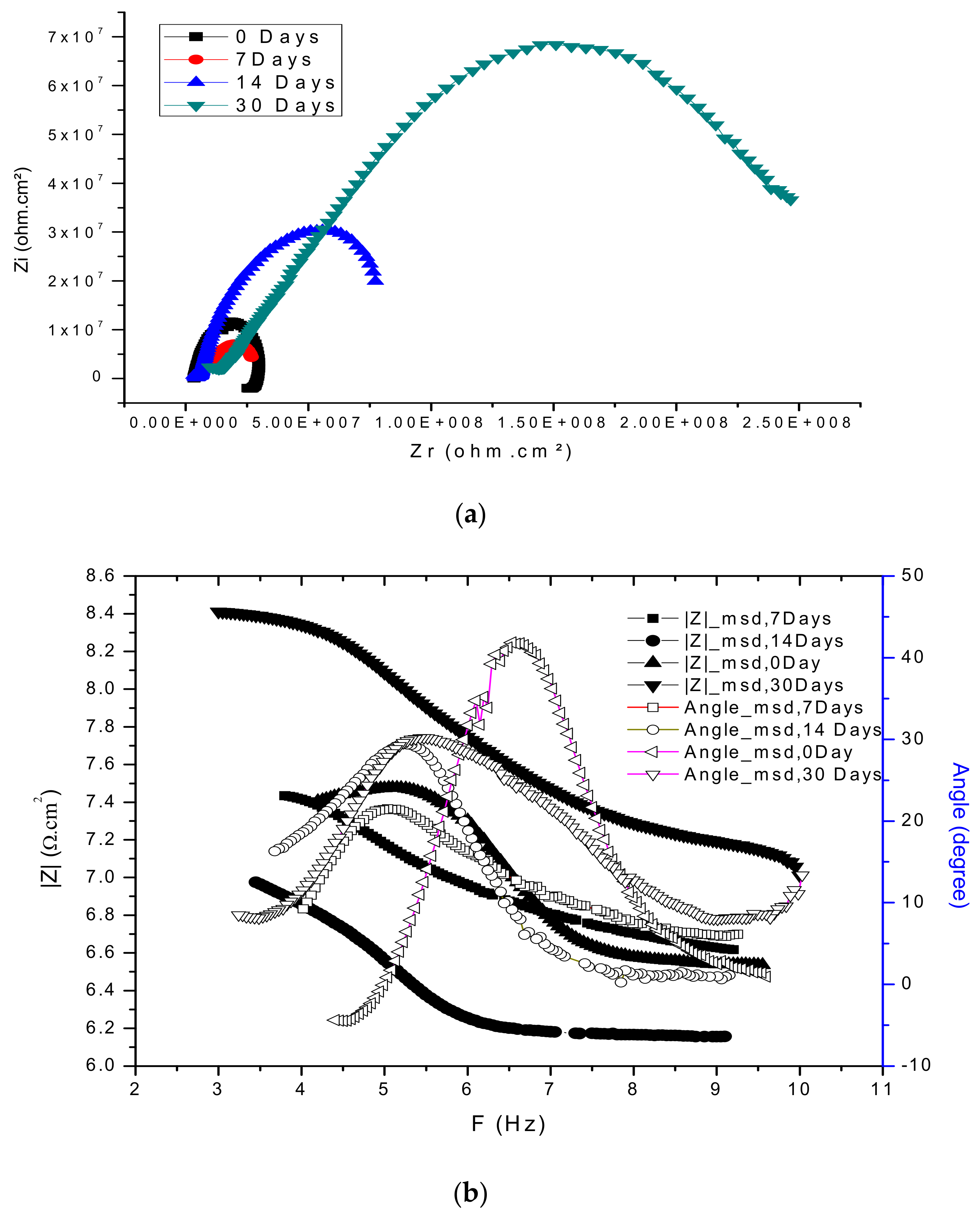
Current densities increase appreciably at high over potentials; for example, for the 2000 mV/ESC electrode potential, the current density is approximately 300 times the density of the instantaneous current (at corrosion potential) for the surface with 0 days and for the surface maintained for 7 days in the SBF, but the increase is higher for alloy maintained for 14 days in SBF. This causes a pronounced corrosion of the alloys in a short period of time (a complete cycle takes about 8.5 min). The evolution of the alloy surface and its behavior at immersion in the SBF solution was analyzed on the basis of the Nyquist, Bode diagrams and equivalent circuits best describing the data obtained from the EIS measurements on the freshly polished and cleaned surface and after maintaining the samples immersed 0, 7, 14 and 30 days, respectively, in the SBF. These are shown in Figure 6a,b.
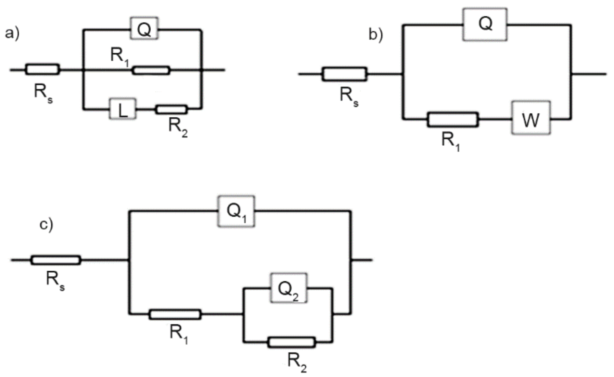
For the freshly polished sample, in the Nyquist diagram the curve does not have a perfect semicircle but presents an additional low-frequency loop, characteristic of an inductive behavior of the electrochemical system. The presence of a negative lobe in the low-frequency range is often attributed to a process of adsorption of some species of solution on the surface of the electrode. These particles may even be solid reaction products. In the equivalent circuit of Figure 7a the presence of the negative lobe at low frequencies is marked by the inductance L, which has a relatively high value. In this equivalent circuit; Rs—represents the ohmic resistance of the electrolyte between the working electrode and the reference electrode; R1—the load transfer resistance through the double-electric layer (the polarization resistance); Q—the constant phase element parameter (CPE) in the impedance expression which characterizes the double-electric layer (ZCPE = Q − 1 (jω) − 1, where j = (−1)½ and ω = 2 πf—angular frequency); and L and R2—inductance and resistance of particle layer adsorbed at the interface/electrolyte.
Considering the value of the frequency exponent in the ZCPE expression (n = 0.794), Q has the meaning of an imperfect capacitor that characterizes the double-electric layer (the double-electric layer appears as a diffuse dispersed capacitor due to chemical microscopic heterogeneities on the surface of the metal). The values of the electrical components of the equivalent circuit (A) of Figure 7 are shown in Table 4.
In the case of the freshly polished surface, the relatively low polarization value indicates a high corrosion rate, and the adsorption of ions from the solution and/or the soil-reaction products leads to alteration of the double-electric layer and even produces some inductive effects under the action of current low-frequency sine wave.
In the case of the sample immersed for seven days in SBF, the equivalent circuit (b) in Figure 7 is particularly simple and shapes a cell in which the delivery is due both to the kinetic process (the chemical reaction that takes place by load transfer) and to a diffusion process of loads through the product surface formed on the surface while maintaining the sample in the solution. Here, Rs is the resistance of the electrolyte, R1 represents the polarization resistance, and W is a diffusion resistance, called Warburg impedance, due to the influence of diffusion of oxidative and reducing species on the overall reaction velocity (corrosion). The constant phase element Q, which in theory should represent the capacity of the double-electric layer, is also an imperfect capacitor (n < 1), probably due to the same imperfections in the structure of the surface as for the freshly polished surface. Element values of this equivalent circuit are shown in Table 4.
The equivalent circuit (c), which describes the physical state of the sample surface for the sample immersed for 14 days in the SBF as well for the sample immersed for 30 days, is characteristic of a metal coated with an imperfect, highly permeable layer.
In this circuit, Rs—the resistance of the electrolyte, R1 and Q1, respectively—is the capacity that characterizes the porous or cracked layer, and R2 and Q2 are the strength and capacity of the double-electric layer. R2 is actually the polarization resistance. Taking into account the numerical values of the frequency exponents (n1 and n2) presented in Table 4, it can be concluded that both the double-electric layer and the coating are not represented by ideal capacitors due to the same causes as in the case of previous samples.
4. Conclusions
Based on the experimental results, it is fair to think that once a new Fe-base alloy surface is exposed to a simulated body fluid solution, a complex oxide layer (FeO/MnO/SiO/CaO/MgO) immediately grows on the surface. The stability of the new layer decreased in time in the presence of the simulated body fluid and after a time period passed to the solution. Fe3O4 partially changed to Fe(OH)2, which subdued precipitation and dissolution mechanisms. The presence of chloride on the interface metal/SBF, as shown in Table 1 (for all samples), maintained a near equilibrium state (homeostasis) between the dissolution of some compounds and the precipitation process and passing to solution. In one case, Fe(OH)2 reacted with chloride and formed soluble FeCl3. After the cleaning stage, no further chloride was identified on the surface. CaO and MgO products are extremely unstable in the simulated body fluid solution. Both oxides became Ca(OH)2 and Mg(OH)2 and interacted on the surface with and precipitated on the surface (Table 1). It appeared that a major part of these compounds was not stable on the surface and passed to solution after the sonication cleaning stage [22]. Each time the oxide layer formed on the top of the alloy surface and came into contact with the simulated body fluid, the solution could not prevent the diffusion of the solution ions and the degradation continued until the end of the metallic material. In conclusion, the passivation layer protects the metallic surface only for a short time period and the galvanic corrosion will take place until the total dissolution of the material [23].
From the experimental results, a simple corrosion model of the FeMnSi–MgCa alloy is proposed, as shown in Figure 8. First, when the metallic material comes into contact with the solution, a complex oxide layer (FeO/MnO/SiO/MgO/CaO) grows and, at least at the beginning, protects the metallic material. The mechanisms of corrosion are presented in different articles [24,25,26,27] and the experimental results, Figure 3 and Figure 4, are in total agreement. Second, the oxides interact with the solution and form hydroxides and grow a new layer with a lower stability (Figure 8b) that continuously interacts with chloride ions to form soluble compounds that pass to the SBF solution, as confirmed by Table 1 and Figure 1 experimental results. At the same time, the carbonate compounds attach to the alloy surface and decrease the corrosion rate because of their non-conductive nature.
In the last stage, the metallic surface will have metallic material parts close to spalling, metallic material holes after the alloy passes to solution, with oxides, hydroxides, carbonates and salts on the surface as shown in Figure 1 and Figure 2. After sonication, an important part of these compounds was removed from the surface. Further work in in vivo tests of this new material is proposed to evaluate the behavior of the material in real conditions in short, medium, or long periods. The compounds formed on the surface must be clearly established using XPS or AES (Auger electron spectroscopy) equipment to obtain a proper degradation model of the material.
We obtained a new experimental alloy based on iron with a corrosion rate (around 700 µm/year) smaller than the Mg-based alloys, but higher than the usual iron-based alloys suitable for medical applications with elements with thicknesses between 500 and 1000 µm.
- We demonstrated that micro-alloying the FeMnSi alloy with Ca and Mg elements resulted in obtaining an α-phase microstructure in a melted state with finely distributed Ca and Mg elements.
- By adding small quantities of Ca and Mg, the corrosion rate in SBF can be increased due to the formation of fine precipitates and also by changing the mechanical behavior and initial corrosion mechanism of the alloy. Further work in in vivo tests of this new material is proposed to evaluate the behavior of the material in real conditions in short, medium, or long periods.
- When introducing and maintaining the FeMnSi–MgCa alloy in artificial blood plasma (SBF), the corrosion process starts from the initial moment and continues throughout the immersion period. Initially, corrosion products (possibly iron and manganese oxides) are adsorbed as microparticles on the surface of the alloy; over time, a compact layer is formed on the surface, which allows the transfer of diffusion loads. After a longer period in the solution, the compact layer deteriorates (becomes porous or cracked) and continues the corrosion in the form of crevasses.
Author Contributions
Conceptualization, N.C.; Funding acquisition, N.C.; Investigation, N.C.; B.I.; R.C. and G.Z.; Methodology, F.S. and R.C.; Supervision, R.C.; Validation, F.S.; B.I. and G.Z.; Writing—original draft, N.C. and R.C.
Funding
This research was funded by a research grant of the TUIASI, project number 1420/2018: Design and characterization of a multifunctional element with memory effect for medical applications, code TUIASI-GI-2018—PN-III-P1-1.1-TE-2016-1420.
Conflicts of Interest
The authors declare no conflict of interest.
References
- Manam, N.S.; Harun, W.S.W.; Shri, D.N.A.; Ghani, S.A.C.; Kurniawan, T.; Ismail, M.H.; Ibrahim, M.H.I. Study of corrosion in biocompatible metals for implants: A review. J. Alloy. Compd. 2017, 701, 698–715. [Google Scholar] [CrossRef]
- Zheng, Y.F.; Gu, X.N.; Witte, F. Biodegradable metals. Mater. Sci. Eng. R Rep. 2014, 77, 1–34. [Google Scholar] [CrossRef]
- Kafri, A.; Shira, O.; Goldman, J.; Drelich, J.; Aghion, E. The Suitability of Zn-1.3%Fe Alloy as a Biodegradable Implant Material. Metals 2018, 8, 153. [Google Scholar] [CrossRef]
- Moravej, M.; Purnama, A.; Fiset, M.; Couet, J.; Mantovani, D. Electroformed pure iron as a new biomaterial for degradable stents: In vitro degradation and preliminary cell viability studies. Acta Biomater. 2010, 6, 1843–1851. [Google Scholar] [CrossRef] [PubMed]
- Schinhammer, M.; Hänzi, A.C.; Löffler, J.F.; Uggowitzer, P.J. Design strategy for biodegradable Fe-based alloys for medical applications. Acta Biomater. 2010, 6, 1705–1713. [Google Scholar] [CrossRef] [PubMed]
- Wang, H.; Zheng, Y.; Liu, J.; Jiang, C.; Li, Y. In vitro corrosion properties and cytocompatibility of Fe-Ga alloys as potential biodegradable metallic materials. Mater. Sci. Eng. C 2017, 71, 60–66. [Google Scholar] [CrossRef] [PubMed]
- Ozkan, K.; Adil, T.; Melih, U.; Baver, A.; Ferhat, G. Fixation of medial malleolar fractures with magnesium bioabsorbable headless compression screws: Short-term clinical and radiological outcomes in eleven patients. Arch. Orthop. Trauma Surg. 2018, 1–7. [Google Scholar] [CrossRef]
- Mostavan, A.; Paternoster, C.; Tolouei, R.; Ghali, E.; Dubé, D.; Mantovani, D. Effect of electrolyte composition and deposition current for Fe/Fe-P electroformed bilayers for biodegradable metallic medical applications. Mater. Sci. Eng. C 2017, 70, 195–206. [Google Scholar] [CrossRef] [PubMed]
- Obayi, C.S.; Tolouei, R.; Paternoster, C.; Turgeon, S.; Okorie, B.A.; Obikwelu, D.O.; Cassar, G.; Buhagiar, J.; Mantovan, D. Influence of cross-rolling on the micro-texture and biodegradation of pure iron as biodegradable material for medical implants. Acta Biomater. 2015, 17, 68–77. [Google Scholar] [CrossRef] [PubMed]
- Im, S.H.; Jung, Y.; Kim, S.H. Current status and future direction of biodegradable metallic and polymeric vascular scaffolds for next-generation stents. Acta Biomater. 2017, 60, 3–22. [Google Scholar] [CrossRef] [PubMed]
- Windhagen, H.; Radtke, K.; Weizbauer, A.; Diekmann, J.; Noll, Y.; Kreimeyer, U.; Schavan, R.; Stukenborg-Colsman, C.; Waizy, H. Biodegradable magnesium-based screw clinically equivalent to titanium screw in hallux valgus surgery: Short term results of the first prospective, randomized, controlled clinical pilot study. Biomed. Eng. Online 2013, 3, 62. [Google Scholar] [CrossRef] [PubMed]
- Hashmi, M.U.; Saqlain, S.A. Dissolution behavior of bioactive glass ceramics with different CaO/MgO ratios in SBF-K9 and r-SBF. Prog. Nat. Sci.-Mater. 2014, 24, 354–363. [Google Scholar] [CrossRef]
- Armarego, W.L.F. Chapter 4—Purification of Inorganic and Metal-Organic Chemicals in Purification of Laboratory Chemicals; Butterworth-Heinemann: Oxford, UK, 2017; pp. 635–770. ISBN 9780128054574. [Google Scholar]
- Shi, S.Q.; Wen, C.; Kaiwen, L.; Changlei, X.; Dongmao, Z. Phase transitions of carbon-encapsulated iron oxide nanoparticles during the carbonization of cellulose at various pyrolysis temperatures. J. Anal. Appl. Pyrol. 2015, 115, 1–6. [Google Scholar] [CrossRef] [Green Version]
- Daeho, H.; Da-Tren, C.; Velikokhatnyi, O.I.; Abhijit, R.; Boeun, L.; Swink, I.; Issaev, I.; Kuhn, H.A.; Kumta, P.N. Binder-jetting 3D printing and alloy development of new biodegradable Fe-Mn-Ca/Mg alloys. Acta Biomater. 2016, 45, 375–386. [Google Scholar] [CrossRef]
- Gu, X.N.; Zhou, W.R.; Zheng, Y.F.; Cheng, Y.; Wei, S.C.; Zhong, S.P.; Xi, T.F.; Chen, L.J. Corrosion fatigue behaviors of two biomedical Mg alloys-AZ91D and WE43-In simulated body fluid. Acta Biomater. 2010, 6, 4605–4613. [Google Scholar] [CrossRef] [PubMed]
- Izquierdo, J.; Bolat, G.; Cimpoesu, N.; Trinca, L.C.; Mareci, D.; Souto, M.R. Electrochemical characterization of pulsed layer deposited hydroxyapatite-zirconia layers on Ti-21Nb-15Ta-6Zr alloy for biomedical application. Appl. Surf. Sci. 2016, 385, 368–378. [Google Scholar] [CrossRef]
- Hufenbach, J.; Wendrock, H.; Kochta, F.; Kühn, U.; Gebert, A. Novel biodegradable Fe-Mn-C-S alloy with superior mechanical and corrosion properties. Mater. Lett. 2017, 186, 330–333. [Google Scholar] [CrossRef]
- Liu, B.; Zheng, Y.F.; Liquan, R. In vitro investigation of Fe30Mn6Si shape memory alloy as potential biodegradable metallic material. Mater. Lett. 2011, 65, 540–543. [Google Scholar] [CrossRef]
- Cimpoeșu, N.; Trincă, L.C.; Dascălu, G.; Stanciu, S.; Gurlui, S.O.; Mareci, D. Electrochemical Characterization of a New Biodegradable FeMnSi Alloy Coated with Hydroxyapatite-Zirconia by PLD Technique. J. Chem. 2016, 2016. [Google Scholar] [CrossRef]
- Schinhammer, M.; Steiger, P.; Moszner, F.; Löffler, J.F.; Uggowitzer, P.J. Degradation performance of biodegradable Fe–Mn–C(–Pd) alloys. Mater. Sci. Eng. C Mater. Biol. Appl. 2013, 33, 1882–1893. [Google Scholar] [CrossRef] [PubMed]
- Stanciu, S.; Ursanu, A.; Trincă, L.C.; Trofin, A.E.; Solcan, C.; Munteanu, C.; Cimpoesu, N.; Acatrinei, D.; Sindilar, E.V.; Stanciu, T.; et al. Study on the biodegradability of FeMnSi alloy. Environ. Eng. Manag. J. 2016, 15, 973–980. [Google Scholar]
- Liu, Y.; Liu, D.; Zhao, Y.; Chen, M. Corrosion degradation behavior of Mg−Ca alloy with high Ca content. in SBF. Trans. Nonferr. Met. Soc. China 2015, 25, 3339–3347. [Google Scholar] [CrossRef]
- Chelariu, R.; Suditu, G.D.; Mareci, D.; Bolat, G.; Cimpoesu, N.; Leon, F.; Curteanu, S. Prediction of Corrosion Resistance of Some Dental Metallic Materials with an Adaptive Regression Model. JOM 2015, 67, 767–774. [Google Scholar] [CrossRef]
- Asgari, M.; Hang, R.; Wang, C.; Yu, Z.; Li, Z.; Xiao, Y. Biodegradable MetallicWires in Dental and Orthopedic Applications: A Review. Metals 2018, 8, 212. [Google Scholar] [CrossRef]
- Hermawan, H.; Mantovani, D. Process of prototyping coronary stents from biodegradable Fe–Mn Alloys. Acta Biomater. 2013, 9, 8585–8592. [Google Scholar] [CrossRef] [PubMed]
- Zhen, Z.; Xi, T.; Zheng, Y. A review on in vitro corrosion performance test of biodegradable metallic materials. Trans. Nonferr. Met. Soc. China 2013, 23, 2283–2293. [Google Scholar] [CrossRef]
Figure 1.
2D and 3D structural aspects (the augmenting of the image of 1000×) of the surface of FeMnSi–MgCa alloy (a,b) initial surface, (c,d) the surface after seven days, (e,f) the surface after 14 days, and (g,h) the surface after 30 days.
Figure 1.
2D and 3D structural aspects (the augmenting of the image of 1000×) of the surface of FeMnSi–MgCa alloy (a,b) initial surface, (c,d) the surface after seven days, (e,f) the surface after 14 days, and (g,h) the surface after 30 days.

Figure 2.
Chemical analysis of the metallic surface after a 7 (a), 14 (b), and 30 (c) days immersion periods.
Figure 2.
Chemical analysis of the metallic surface after a 7 (a), 14 (b), and 30 (c) days immersion periods.
Figure 3.
Chemical elements (Fe, Mn, Si, Mg, Ca, O, Na, C, and Cl) mass % variation EDX determinations; (a) after immersion and (b) after immersion and sonication cleaning.
Figure 3.
Chemical elements (Fe, Mn, Si, Mg, Ca, O, Na, C, and Cl) mass % variation EDX determinations; (a) after immersion and (b) after immersion and sonication cleaning.

Figure 4.
X-ray diffraction (XRD) graph of the FeMnSi + MgCa alloy’s initial state and after different immersion periods in simulated body fluid (SBF) solution.
Figure 4.
X-ray diffraction (XRD) graph of the FeMnSi + MgCa alloy’s initial state and after different immersion periods in simulated body fluid (SBF) solution.

Figure 5.
Linear polarization: (a) Tafel diagrams of the experimental alloy behavior; (b) cyclic diagrams of the experimental alloy behavior; (c) surface statement after the electrochemical corrosion test; and (d) chemical element distributions on the corroded surface.
Figure 5.
Linear polarization: (a) Tafel diagrams of the experimental alloy behavior; (b) cyclic diagrams of the experimental alloy behavior; (c) surface statement after the electrochemical corrosion test; and (d) chemical element distributions on the corroded surface.

Figure 6.
Electro impedance spectroscopy of the experimental alloy: (a) Nyquist; and (b) Bode diagrams.
Figure 6.
Electro impedance spectroscopy of the experimental alloy: (a) Nyquist; and (b) Bode diagrams.

Figure 7.
Equivalent circuits for alloy behavior: (a) initial sample, (b) after 7 days’ immersion; and (c) after 14 and 30 days immersion.
Figure 7.
Equivalent circuits for alloy behavior: (a) initial sample, (b) after 7 days’ immersion; and (c) after 14 and 30 days immersion.

Figure 8.
Growth of oxide/hydroxides/carbonates multi-layers on the surface of the FeMnSi–MgCa alloy in strength contact with SBF. (a) Initiation of corrosion; (b) after a few hours; and (c) after a few days in SBF solution.
Figure 8.
Growth of oxide/hydroxides/carbonates multi-layers on the surface of the FeMnSi–MgCa alloy in strength contact with SBF. (a) Initiation of corrosion; (b) after a few hours; and (c) after a few days in SBF solution.

Table 1.
Chemical composition of immersion solution.
| Chemical Composition (Ions) (mmol/dm3) | Na+ | K+ | Mg2+ | Ca2+ | Cl− | HCO3− | HPO42− | SO42− |
|---|---|---|---|---|---|---|---|---|
| Simulated body fluid | 142 | 5 | 1.5 | 2.5 | 147.8 | 4.2 | 1 | 0.5 |
| Human blood plasma | 142 | 5 | 1.5 | 2.5 | 103 | 27 | 1 | 0.5 |
Table 2.
Weight measurements after immersion in SBF 1.5% at 37 °C.
| Sample/Dimension | Length (mm) | Width (mm) | Thickness (mm) | Total Area (mm2) | Initial Weight (g) | Weight after Immersion (g) | Weight after Immersion + Sonication (g) |
|---|---|---|---|---|---|---|---|
| 7 days | 10.1 | 6.94 | 4.54 | 294.91 | 2.397 | 2.380 | 2.3706 |
| 14 days | 10.25 | 6.98 | 4.54 | 299.54 | 2.426 | 2.401 | 2.372 |
| 30 days | 10.03 | 6.83 | 4.54 | 290.1 | 2.310 | 2.279 | 2.265 |
Table 3.
Electrochemical corrosion parameters of FeMnSi–MgCa in SBF solution.
| Parameter | 0 Days | 7 Days | 14 Days | 30 Days |
|---|---|---|---|---|
| OCP (mV) | −753 | −713 | −679 | −751 |
| Ecor (Ej=0) (mV) | −682 | −681 | −727 | −677.9 |
| Rp (ohm · cm2) | 49.01 | 383.31 | 17.71 | 19.14 |
| bamV | 168 | 82 | 158 | 164.5 |
| bcmV | −1340 | −280 | −451 | −1116.3 |
| jcorr (mA/cm2) | 0.695 | 0.0571 | 2.022 | 1.7740 |
| vcor (mm/year) | 8.126 | 0.668 | 23.640 | 20.74 |
| Rp = (dE/dj)E (Ω · cm2) | 47.98 | 340.49 | 17.87 | 18.60 |
Table 4.
Equivalent circuit parameters describing the electrochemical impedance spectroscopy (EIS) behavior of the 0, 7, 14, and 30 days samples.
Table 4.
Equivalent circuit parameters describing the electrochemical impedance spectroscopy (EIS) behavior of the 0, 7, 14, and 30 days samples.
| Parameters | Rs (ohm · cm2) | Q1 (S · sn/cm2) | n1 | R1 (kohm · cm2) | Q2, S · sn/cm2 | n2 | L (Henry · cm2) | W (S · s½ · cm2) | R2 (kohm · cm2) | χ2 |
|---|---|---|---|---|---|---|---|---|---|---|
| 0 Days | 444.6 | 12.1210−6 | 0.694 | 3.863 | - | - | 108.2 | - | 1.096 | 5.70 10−4 |
| 7 Days | 712.8 | 30.1 10−6 | 0.721 | 3.409 | - | - | - | 2.21 10−4 | - | 1.86 10−4 |
| 14 Days | 587.4 | 30.6 10−6 | 0.730 | 2.651 | 2.21 10−4 | 0.799 | - | - | 1.695 | 1.86 10−4 |
| 30 Days | 447.8 | 7.81 10−5 | 0.435 | 1.007 103 | 2.24 10−5 | 0.797 | - | - | 3.239 × 10³ | - |
© 2018 by the authors. Licensee MDPI, Basel, Switzerland. This article is an open access article distributed under the terms and conditions of the Creative Commons Attribution (CC BY) license (http://creativecommons.org/licenses/by/4.0/).
Share and Cite
MDPI and ACS Style
Cimpoeşu, N.; Săndulache, F.; Istrate, B.; Cimpoeşu, R.; Zegan, G. Electrochemical Behavior of Biodegradable FeMnSi–MgCa Alloy. Metals 2018, 8, 541. https://doi.org/10.3390/met8070541
AMA Style
Cimpoeşu N, Săndulache F, Istrate B, Cimpoeşu R, Zegan G. Electrochemical Behavior of Biodegradable FeMnSi–MgCa Alloy. Metals. 2018; 8(7):541. https://doi.org/10.3390/met8070541
Chicago/Turabian StyleCimpoeşu, Nicanor, Florin Săndulache, Bogdan Istrate, Ramona Cimpoeşu, and Georgeta Zegan. 2018. "Electrochemical Behavior of Biodegradable FeMnSi–MgCa Alloy" Metals 8, no. 7: 541. https://doi.org/10.3390/met8070541
Note that from the first issue of 2016, this journal uses article numbers instead of page numbers. See further details here.