Microstructural, Mechanical and Corrosion Investigations of Ship Steel-Aluminum Bimetal Composites Produced by Explosive Welding


Technology Faculty, Karabük University, Karabük 78050, Turkey
Metals 2018, 8(7), 544; https://doi.org/10.3390/met8070544
Submission received: 19 June 2018
/
Revised: 11 July 2018
/
Accepted: 12 July 2018
/
Published: 15 July 2018
Abstract
:In this study, explosive welding was used in the cladding of aluminum plates to ship steel plates at different explosive ratios. Ship steel-aluminum bimetal composite plates were manufactured and the influence of the explosive ratio on the cladded bonding interface was examined. Optical microscopy (OM), scanning electron microscopy (SEM), and energy dispersive spectrometry (EDS) studies were employed for the characterization of the bonding interface of the manufactured ship steel-aluminum bimetal composites. Tensile-shear, notch impact toughness, bending and twisting tests, and microhardness studies were implemented to determine the mechanical features of the bimetal composite materials. In addition, neutral salt spray (NSS) tests were performed in order to examine the corrosion behavior of the bimetal composites.
Keywords:
bimetal composite; explosive welding; ship steel; aluminum; mechanical features; corrosion1. Introduction
Today’s ship and offshore construction designers face complex problems in selecting materials that provide minimization of topside weight and protection against marine corrosion-all within a reasonable budget [1]. With the development of modern industry, applications of single metallic constituents are unable to meet these requirements. Instead, with the respective merits of two metallic components, the bimetal clad plate is capable of achieving the performance that single metal constituents fail to provide [2]. The usual solution to this problem is to employ a variety of metals throughout the structure, each being selected for features appropriate for the specific component [3].
Cladded plates are used today in power plants, for applications in the chemical and petrochemical industry, for desalination plants, in ship construction, etc. In particular, the formation of a metallic continuity of metal combinations that are difficult or impossible to bond by other means is desirable for other applications, such as the automotive and the aerospace industries. Light-weight metals, like titanium, aluminum, and even magnesium can be bonded to other metallic partners like steel or to each other [4].
Aluminum alloy displays the ideal features of low density, high thermal conductivity, and good corrosion resistance [2,5]. Steel/aluminum structural transition joints (STJ) are widely used in the ship-building industry due to the important weight-saving advantages of joining these two materials, while exploiting their best features [6,7,8]. In this arrangement, the total weight of the ship is reduced due to the lighter aluminum superstructure [7,8]. Bars and plates that are made of steel/aluminum alloys with thicknesses greater than 20 mm are of relevant interest. At present, explosive welding is predominantly used to join this material combination. No alternative commercial technology is available that is capable of directly bonding these dissimilar materials with thick proportions [9].
Pure aluminum is used to achieve a satisfactory bond in the steel-aluminum explosive welding. Pure aluminum, thanks to its high melting point, zero freezing range, and high thermal conductivity, reduces the amount and duration of the liquid phase, thereby preventing the formation of fragile intermetallic compounds at the bonding interface. In previous works [10,11,12], steel-(pure) aluminum joints have been successfully achieved using the explosive welding method. However, previous studies have used only the traditional techniques of optical microscopy (OM) and scanning electron microscopy (SEM) for microstructure examinations along with some mechanical tests (tensile-shear, bending) in their evaluations, while the corrosion resistance of these and similar composites was not investigated by exposure under service conditions.
The purpose of this study was to produce a bimetal composite for ship-building applications by cladding plates of ship steel to aluminum plates and to examine the ability of explosive welding to join ship steel and aluminum. In addition to conventional microstructural methods (OM and SEM), the composites were examined via area and linear energy dispersive spectrometry (EDS) analyses, and mechanical tests (tensile-shear, bending) as well as notch impact and torsion tests were applied. Finally, corrosion resistance was determined by neutral salt spray (NSS) tests (in seawater) in accordance with the proposed use of the composites.
2. Experimental Procedure
In this study, ship steel (base plate) and aluminum plates (flyer plate) were bonded via the explosive welding method. The chemical compositions of the ship steel and aluminum plates are given in Table 1. The dimensions of the ship steel and aluminum plates were 250 × 150 × 5 mm and 250 × 150 × 2 mm, respectively. The explosive material, supplied by MKE Barutsan Company (Ankara, Turkey), was Elbar-5 (92% ammonium nitrate, 5.0% fuel-oil, and 3.0% TNT). Preliminary experiments were carried out to determine the explosive ratios to be used in the experimental studies and four different explosive ratios were determined (R = 2, R = 2.5, R = 3, and R = 3.5, R being the weight of the explosive/the weight of the flyer plate). Cladding operations were performed three times for each explosive ratio using the welding parameters in Table 2. A parallel arrangement (Figure 1) was used for the welding setup.
For microstructural, mechanical, and corrosion characterization samples were taken from the bimetal composites. The samples for metallographic observations were cut from the bimetal composites parallel to the explosion direction. The samples were ground and polished to a 3 μm finish and then etched using solutions of 2.5 percent nital for the ship steel and Keller’s reagent for the aluminum. The metallographic examinations of the samples were implemented using a Nikon Epiphot 200 optical microscope (Nikon, Melville, NY, USA). A ZEISS EVO LS 10 (Carl Zeiss SMT GmbH, Oberkochen, Germany) scanning electron microscope equipped with energy dispersive spectrometry (EDS) was used to characterize the microstructure and composition of the bimetal composite bonding interface.
Microhardness changes in the bimetal composite plates were determined using a Shimadzu HV microhardness tester (MCT-W, Shimadzu, Tokyo, Japan). A 500-g load was applied during tests. Each microhardness value was the average of three indentations. In order to determine the mechanical features of the bimetal composite samples, three samples were used for each test and the results were averaged. Tensile-shear tests were implemented according to ASTM D3165-07 (Figure 2) while using a Shimadzu testing machine unit (Shimadzu, Tokyo, Japan). Figure 3 shows the dimensions of a Charpy (V-notch) impact test specimen. Charpy (V-notch) impact tests were done at room temperature on a Charpy impact test machine. Bending tests were carried out in accordance with ASTM A 263-12. The bending tests were applied to the bimetal composites to check the strength of the cladding of the samples under different conditions. The tests were carried out in two ways: with the aluminum cladding material retained inside and with the aluminum cladding material retained outside. The twisting tests of the bimetal composite plates were applied manually with a torque wrench. In order to examine the corrosion behavior of the composite materials in a sea water environment, NSS tests were performed using a SAL 600 TL unit according to corrosion tests/salt spray test standard EN ISO 9227 (for evaluation of resistance to corrosion of metal materials temporarily protected, permanently protected, or unprotected against corrosion). The NSS tests were applied to the bonding interface of the composite samples (covering both materials) for the determination of the corrosion resistance in sea water (5% NaCl) of the base material (ship steel) and cladding material (aluminum) used in the production of the bimetallic composite materials.
3. Results and Discussions
3.1. Metallographic Examination
Figure 4, Figure 5 and Figure 6 show microstructure images at different magnifications of the bonding interfaces of the ship steel-aluminum bimetal composite materials produced via the explosive welding method. All of the images show the ship steel as the base plate and the aluminum as the flyer plate.
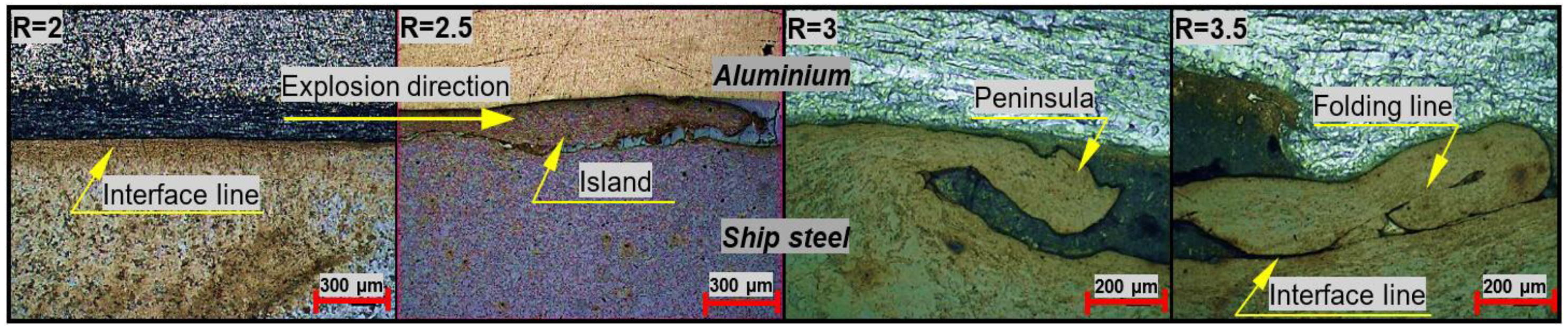
Figure 4 shows that a flat interface was obtained in the bonding interface at the lowest explosive ratio (R = 2). Waving can be seen to start in the bonding interface as the explosive ratio was increased (R = 2.5). As the explosive ratio was further increased (R = 3), significant increases in wavelength (400–500 µm) and amplitude (~120 µm) were seen in the bonding interface. The bonding interface with the highest wavelength (500–600 µm) and amplitude (~160 µm) was the bimetal composite sample that was produced at the highest explosive ratio (R = 3.5). As the explosive ratio increased, the collision velocity of the flyer plate (aluminum) increased, and thus, the impact pressure increased. With this pressure increase, the deformation rate increased and the fluctuation in the interface increased due to the rise in the deformation rate. As a result, as the explosive ratio increased, the waving at the bonding interface increased and parallel to this, the wavelength and the amplitude increased. In the literature [14], it was reported that a pressure wave is generated during the explosive welding process, which gives the base plate and flyer plate specific and usually very high velocities. The collision of plates with such high velocities triggers a pressure of up to 1-2 atm × 105 Pa. This pressure makes it possible to obtain physical states unattainable under static loads. In addition, some previous studies [15,16,17,18,19] have reported that an increasing explosive amount increased the collision rate and impact pressure, and these, in turn, caused the joining interface to change from a straight form to a wavy one. It was also reported that an increase in the amount of explosive increased the wavelength and amplitude.
Additionally, ship steel wave folding (mechanical locking) occurred in the bonding interface and folded parts were locked in the aluminum flyer plate due to the impact pressure that is generated in parallel with the increase in the explosive ratio (Figure 5). These wave folds and the locking increase the interface surface area. The increase in the bonding surface field results in the development of bonding interface strength. It has been noted in the literature [20,21,22] that a wavy bonding interface is usually desirable in explosive welding, since it ensures a larger bonding interface field as well as greater bonding strength. Moreover, small peninsular and island-shaped ship steel sections can be observed on the aluminum side of the bonding interface. These small islands are thought to have left the ship steel and formed at the bonding interface as an effect of the pressure generated during the explosive welding. In previous studies [13,23], it was reported that peninsular and island-like morphologies could be formed at the interface as an effect of the detonation force and metal vortex flow during high explosive welding.
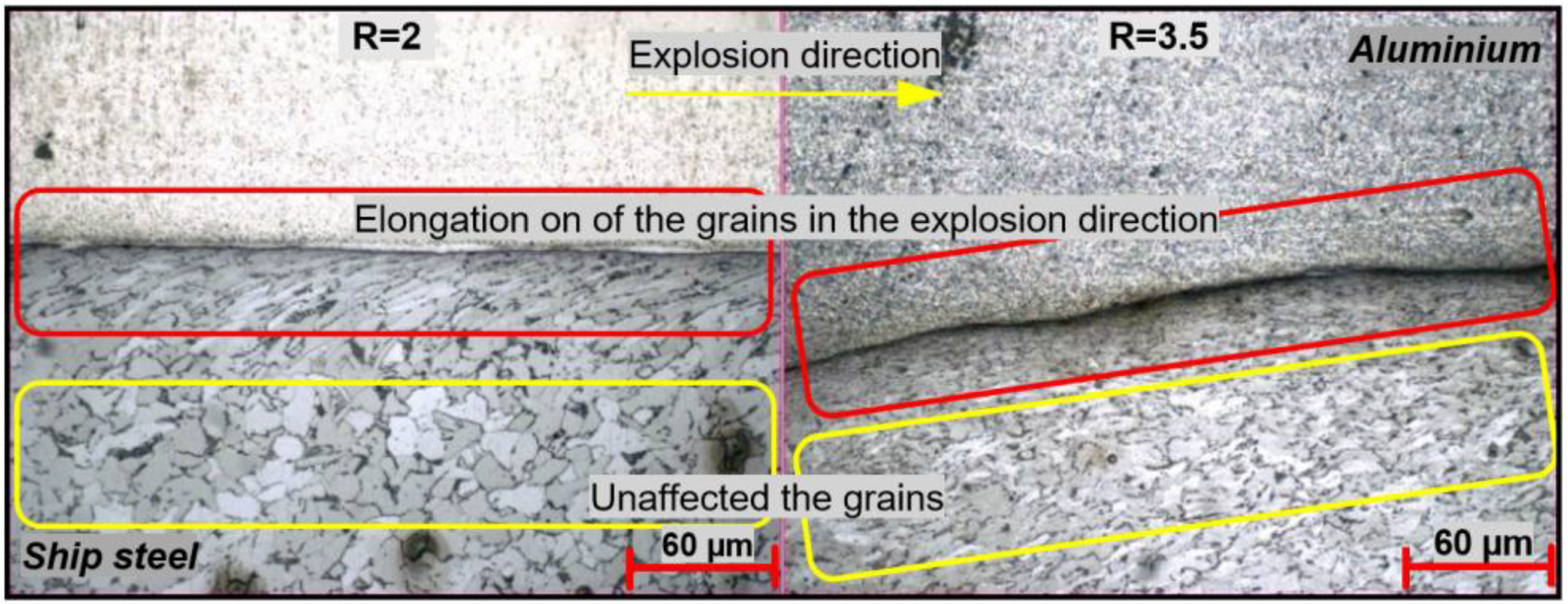
Furthermore, grains that were close to the bonding interface extended parallel to the explosion direction during explosive welding. This effect gradually disappeared at distances moving further away from the interface (Figure 6). Mastanaiah et al. [24] reported that grains close to the welded interface were generally elongated parallel to the explosion direction and were caused by the highly localized plastic deformation occurring during the collision between the plates. Additionally, Athar and Tolaminejad [25] reported that an increase in the explosive ratio might affect not only the bonding interface morphology, but also the depth of the field that is affected by the deformation.
3.2. SEM and EDS Analysis
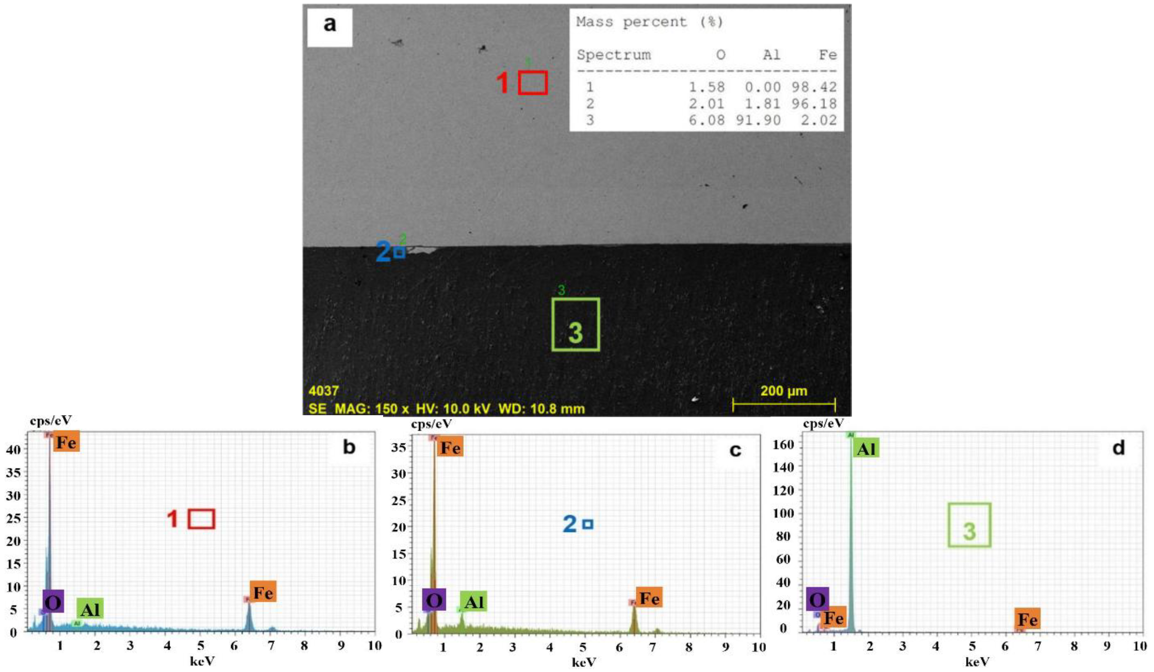
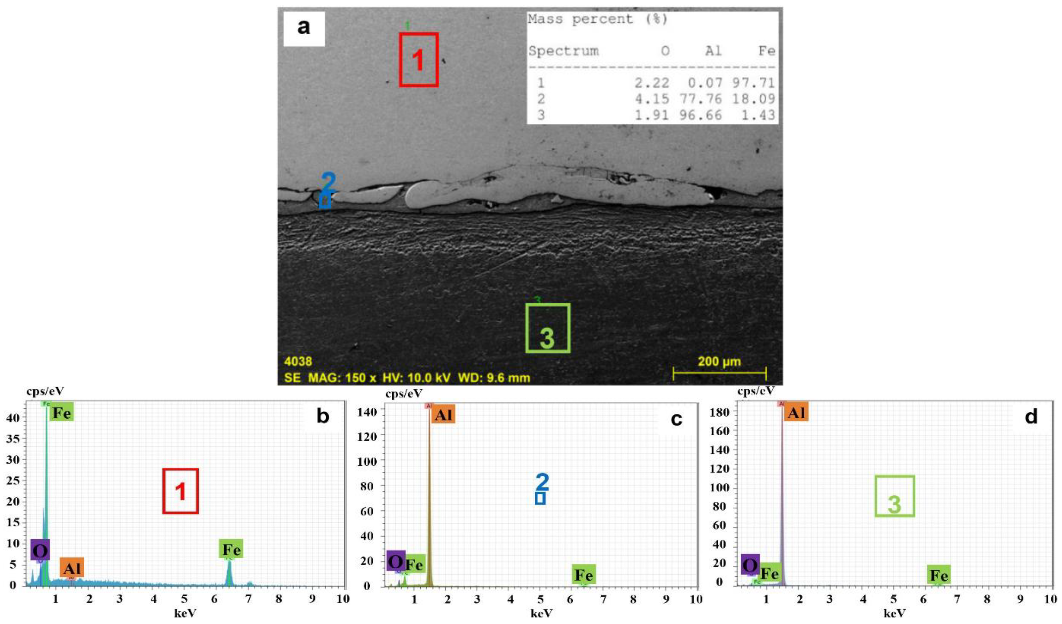
Figure 7, Figure 8, Figure 9 and Figure 10 show SEM images and EDS analyses of the bonding interfaces for the different explosive ratios. All of the images show the upper field as the ship steel base plate and the lower field as the aluminum flyer plate.
The SEM image of the composite bonding interface that is produced at the lowest explosive ratio (Figure 7) shows that a flat interface was obtained. As a result of the EDS analysis performed on the fields indicated on the SEM image, the chemical features were determined as Fe (98.42%) for the base plate material in Field-1 and as Al (91.90%) for the flyer plate material in Field 3. The presence of Fe (96.18%) was determined in Field-2 even though this region close to the joining interface was on the Al (the flyer plate material). In addition, Al (1.81%) and oxide (2.01%) residues were detected in very small quantities in Field-2. In conclusion, it can be said that there was no diffusion in this welding operation where the lowest explosive ratio (R = 2) was used.
The SEM image of the composite bonding interface produced at the R = 2.5 explosive ratio (Figure 8) shows the waving that started in the bonding interface. As a result of the EDS analysis that was performed on the fields indicated on the SEM image, the chemical features of the base plate material of Fe (97.71%) in Field-1 and of the flyer plate material of Al (96.66%) in Field-3 were determined. On the other hand, Field-2 on the bonding interface was found to consist of approximately 78% Al, 18% Fe, and 4% oxide. The Fe-Al balance diagram in the literature [26] was examined and showed that the FeAl3 + αAl layer occurred from the sub-eutectic temperature of 652 °C to room temperature.
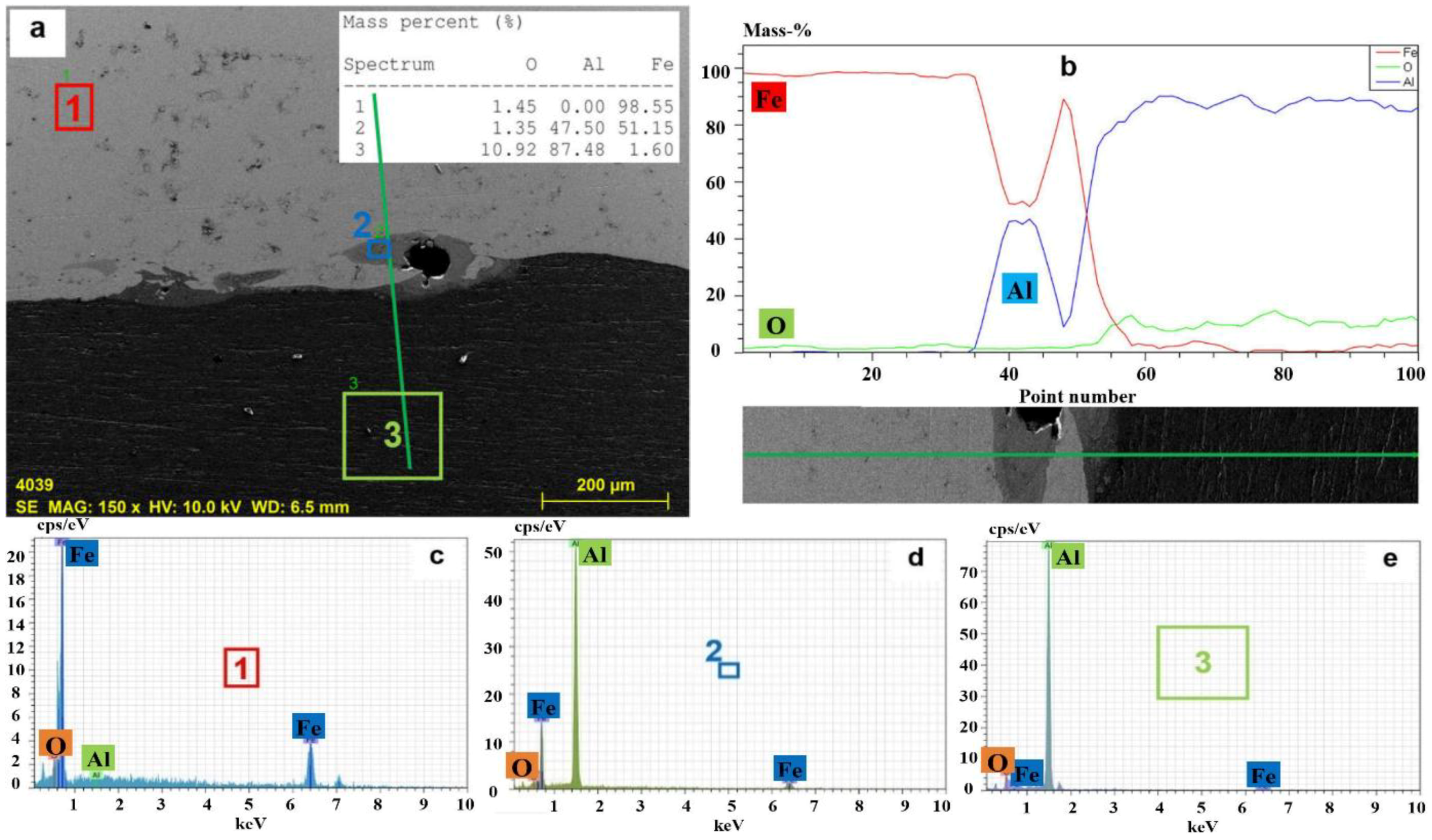
The SEM image of the composite bonding interface produced at the R = 3 explosive ratio (Figure 9) shows that an increase occurred in the wavelength and amplitude in the bonding interface. As a result of the EDS analysis that was performed on the fields indicated on the SEM image, the chemical features of the base plate material of Fe (98.55%) in Field-1 and of the flyer plate material of Al (87.48%) in Field-3 were determined. However, Field-2 on the base plate material of Fe close to the bonding interface was found to consist of approximately 51% Al, 48% Fe, and 1% oxide. By examining the Fe-Al balance diagram [26], the α2 layer was determined, in which 35–50% of the Fe and Al atoms had dissolved into each other at room temperature. Moreover, the linear EDS analysis performed on this field confirmed the results.
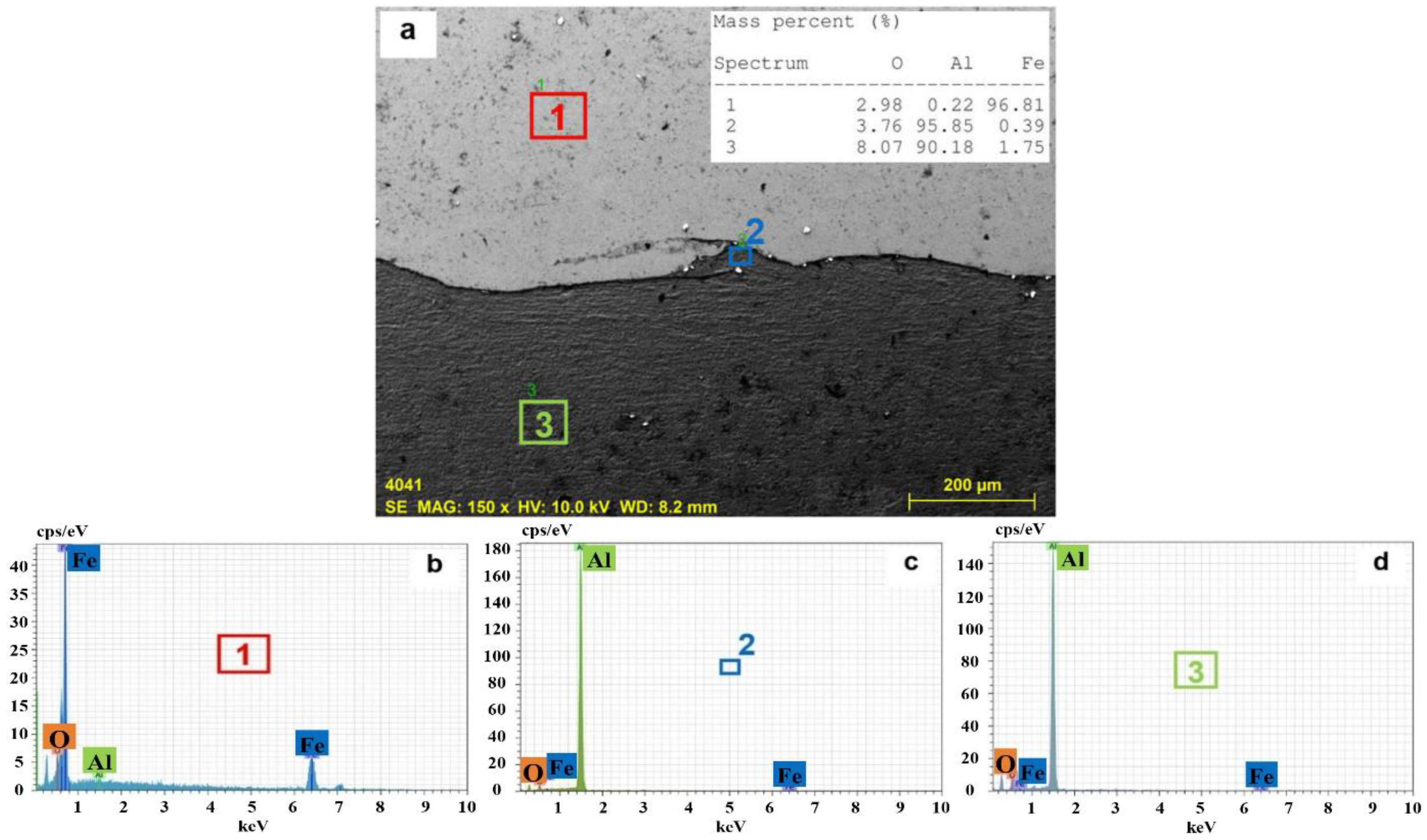
The SEM image of the composite bonding interface produced at the highest explosive ratio (R = 3.5) was the image where the wavelength and amplitude in the bonding interface were the most evident (Figure 10). As a result of the EDS analysis that was performed on the fields indicated on the SEM image, the chemical features of the base plate material of Fe (96.81%) in Field-1 and the flyer plate material of Al (90.18%) in Field-3 were determined. The Field-2 region on the flyer plate material of Al near the joining interface was approximately 96% Al, 4% oxide, and 0.4% Fe.
As a result, it was found that a flat interface was obtained with a low explosive ratio and no intermetallic formation was observed. In addition, as the explosive ratio increased, the wavy structure formed by mechanical interlocking occurred at the interface and some intermetallic compounds were formed. It is thought that the low explosive ratio at the interface did not generate a high enough temperature to create intermetallic forms, while at high explosive ratios, the temperature was reached at which intermetallic forms could be seen as part of the interface.
3.3. Tensile-Shear Test Results
Table 3 shows the tensile-shear test results of the bonding interfaces for the different explosive ratios. It is seen that the tensile-shear strength increased by approximately 10% at increasing explosive ratios (from R = 2 to R = 3.5). As seen in Figure 4, the bimetal composite interface transits from a flat form to a wavy one at increasing explosive ratios, and the bonding interface field increases as a result of increasing wavelength/amplitude. Moreover, wave folding (mechanical locking) was formed in the bimetal composite bonding interface due to the impact of the pressure that was generated from the increase in the explosive ratio (Figure 5). As a result, the tensile-shear strength increased with the expanded bonding interface field and the wave folding.
Athar and Tolaminejad [25] reported that wavy interfaces that were generated from increases in explosive ratio and impact pressure expanded the bonding interface field, which subsequently increased tensile-shear strength slightly. The authors also added that the impact pressure and sudden shock hardening, due to the increasing explosive ratio, and the grain refinement, due to the cold deformation in the bonding field, resulted in greater strength. In another study, Xie et al. [27] reported that waving in the bonding interface ensured better mechanical locking between the flyer plate and the base plate and higher bonding interface strength.
The fracture images after the tensile-shear test (Figure 11) show that there was no separation in the bonding interface in any of the bimetal composite samples; however, cracking occurred in the upper aluminum plate in all composites produced at different explosive ratios. According to these results, the aluminum cladding material was successfully bonded onto the ship steel base material surface while using the explosive welding method. Bimetal composite plates were produced by Li et al. [2] (Al/Fe), Asemabadi et al. [28] (Al/Cu) and Loureiro et al. [29] (Cu/Al) and using the explosive welding method, and they reported that after tensile-shear tests, no separation was seen in the bonding interface.
3.4. Charpy Impact Toughness Results
Table 4 shows the Charpy impact toughness test results of the samples at room temperature. Samples of 55 × 10 × ~7 mm in dimension were used. The impact toughness of the bimetal composite samples decreased as the explosive ratio increased. The amount of deformation in the materials had increased due to the increased pressure in parallel with the increasing explosive ratio. The decrease in impact toughness dependent on the explosive ratio was a result of high plastic deformation. In a similar study, Kaya and Kahraman [1] produced Grade A/AISI 316L bimetal composite plates while using the explosive welding method at different explosive ratios, and the results of the Charpy notch impact toughness test showed that deformation hardening increased as a result of an increasing explosive ratio, and thus, the impact toughness of the bimetal composites decreased.
Figure 12 shows macro images of samples subjected to the notch impact toughness test at room temperature. When the macro images of samples after the notch impact toughness test were examined, no separation was seen in any of the bimetal composite samples that were produced at different explosive ratios. Cracking occurred in the ship steel (base plate) side of the ship steel-aluminum bimetal composites and although bending was seen in the aluminum (cladding plate) side, no separation was present. Kaçar and Acarer [30] cladded P355GH and AISI 316L and reported that after notch impact toughness tests at different temperatures, cracking was present on the base material only (P355GH), while no cracking was seen on the cladding material (AISI 316L).
3.5. Bending Test Results
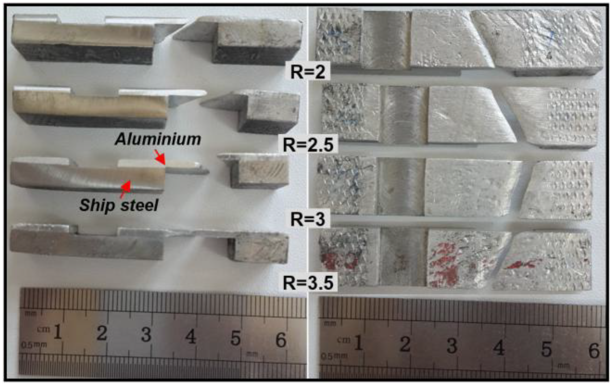
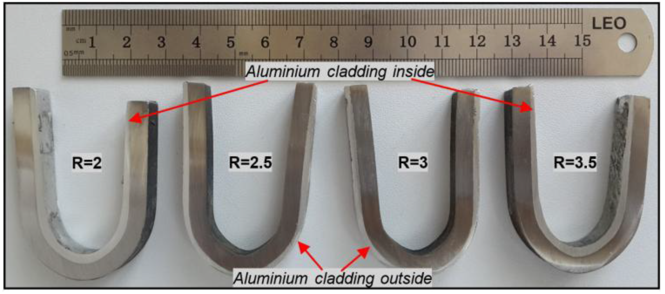
Figure 13 shows macro images that were obtained as a result of the (two-way) bending tests applied to the ship steel-aluminum bimetal composite samples that were produced via explosive welding with the cladding plate (aluminum) extending both inwards and outwards. No visible cracks, fractures, or separations were seen in the bonding interface of the bimetal composite samples produced at different explosive ratios as a result of the two-way bending tests performed by bending the samples 180°.
The fact that no faults were found in the bonding interfaces of the bimetal composite samples as a result of the bending tests indicates that a safe welding was achieved, and these bimetal composites could safely be used under service conditions. It also reported in literature [12,31,32,33] that explosively cladded materials could be bended up to 180°. As there was no defect (cracks or seperation) in the interfaces of the bended specimens, they can be readily used in the bended form in service conditions.
3.6. Twisting Test Results
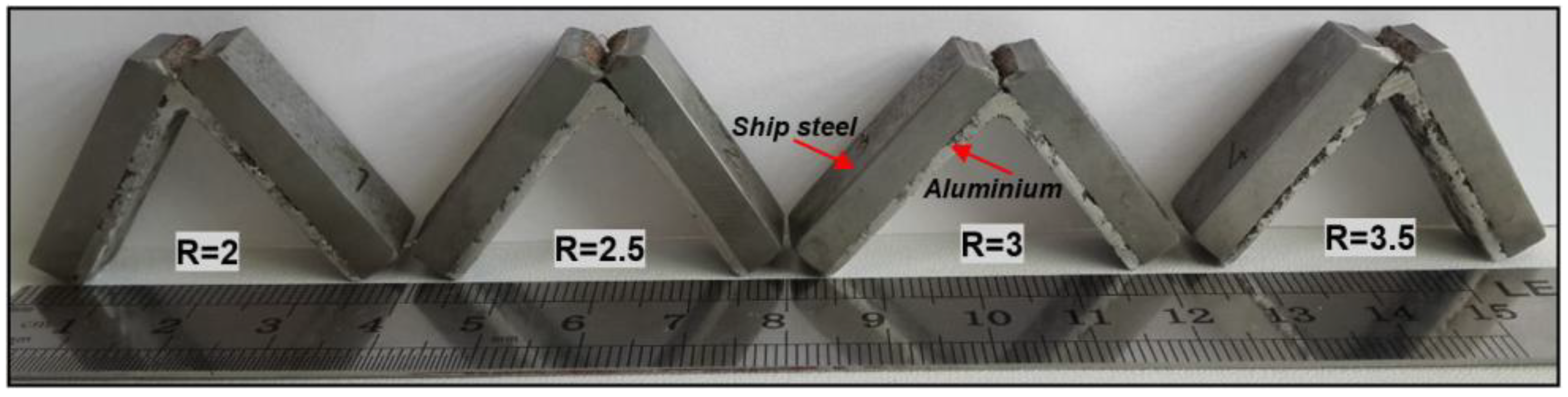
Figure 14 shows macro images that were obtained as a result of the 360° twisting test applied to the ship steel-aluminum bimetal composite samples. After the 360° twisting test was applied to the bimetal composite samples, no cracks or fractures were seen in the bonding interface of any of the composites.
No cracks or fractures occurred in the composite samples and although high strain-hardening levels were achieved, excessive cold deformation was seen in the bimetal composites due to the explosive ratio and the deformation that was applied to the composites in the twisting test. The twisting test once again proved the bonding interface quality of the bimetal composite materials produced. It also showed that the composites were dependable and could be twisted and used under service conditions. Wang et al. [34] performed twisting tests in order to determine the joint quality of copper/steel bimetal composites that were produced with explosive welding and reported that the interface strength was satisfactory and that no cracking had occurred in spite of the high degree of deformation and hardening.
3.7. Microhardness Results
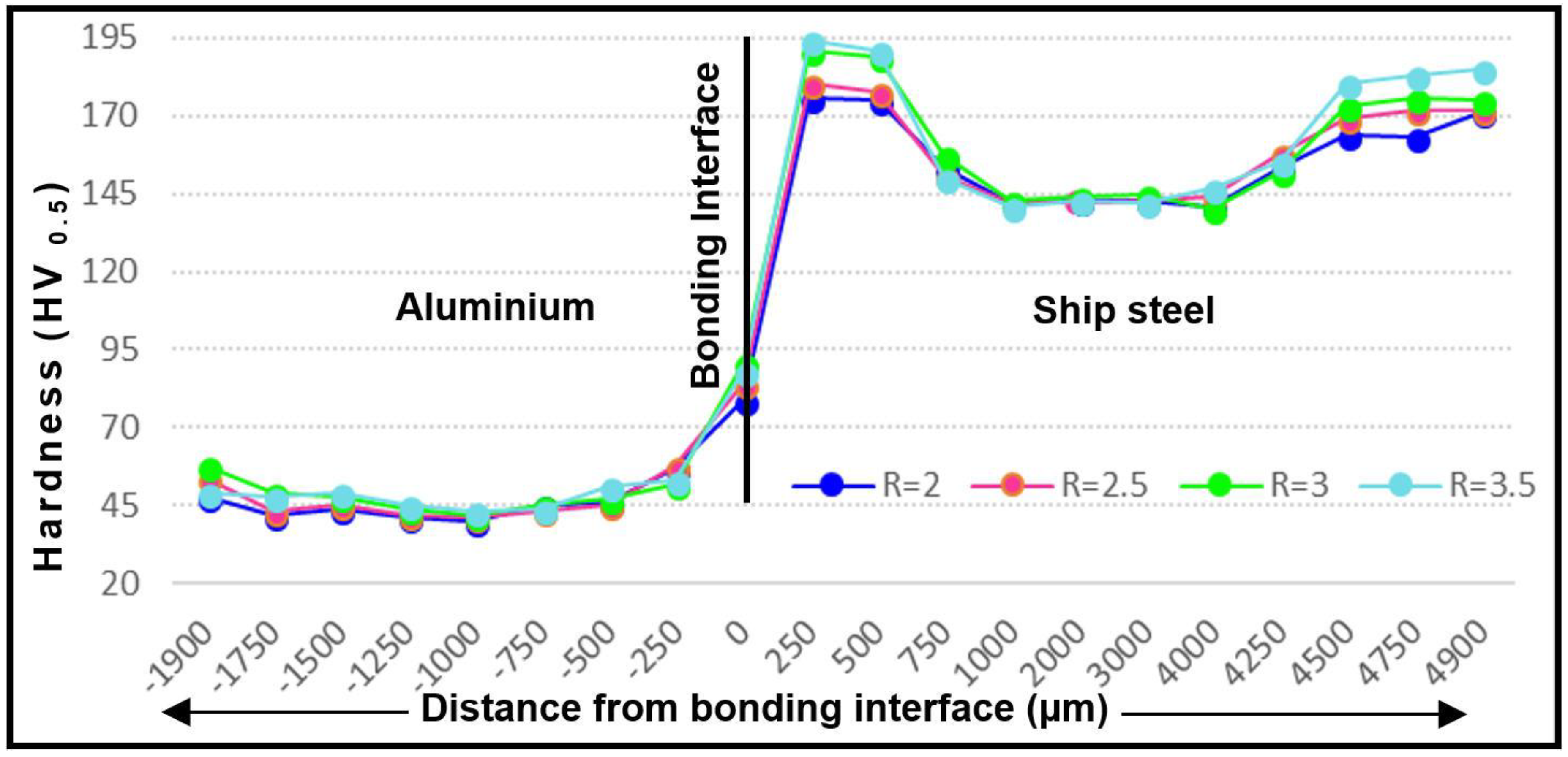
Figure 15 shows results of the microhardness test that was applied to the ship steel-aluminum bimetal composite samples in order to determine the influences of different explosive ratios on the hardness values. When the hardness graph is examined, with increases in the explosive ratio, increases in the hardness values of the bimetal composite joining interface and its vicinity (~750 μm in ship steel/~500 μm in aluminum) were observed. The impact velocity of the plates increased at increasing explosive ratios, and as a result, the deformation levels increased. The increasing deformation levels subsequently increased the hardness values.
When the hardness values of the bimetal composite sheets were examined, a significant increase in hardness was seen near the joining interface and on the outer surfaces of the composite sheets, whereas the hardness values of the thick central areas of the sheets were nearly the same as those of the original materials. Furthermore, from the hardness value increases of the bimetal composite plates, it was understood that the hardness values measured near the joining interface were higher than the hardness values that were measured from the outer surfaces of the plates. In the explosive welding method used to produce the bimetal composite plates, the bonding interface and the outer surface of the plates are exposed to cold deformation due to the impact pressure sustained by the plates, dependent upon the explosive ratio. As understood from the microstructure tests that were applied to the bimetal composite samples (Figure 6), the deformation level decreased at distances moving further away from the bonding interface, and the hardness decreased as a result. For example, whilst the original hardness of ship steel is ~140 HV, it was measured as 176 HV at the R = 2 explosive ratio at a distance of 250 µm (the closest distance to the bonding interface), 175 HV at a distance of 500 μm, ~147 HV at the thickest area at the center (2500 µm), and 171 HV at a distance of 4900 μm (around the ship steel outer surface). For R = 2.5, these values (at the same distances) were measured as 180 HV, 178 HV, 149 HV, and 173 HV, respectively. The hardness profile was similar to these results for the explosive ratios of R = 3 and R = 3.5. Likewise, it was found that the hardness values measured from the aluminum side of the bimetal composite samples increased at increasing explosive ratios. In addition, the hardness value decreased at distances moving further away from the bonding interface of the aluminum side of the bimetal composite material and was close to the original aluminum hardness value (40 HV) at the thick center of the plate. The hardness value increased again at distances that were closer to the outer surface.
Gülenç [35] performed hardness tests on Al/Cu bimetal composite plates he had produced via explosive welding and reported that the reason behind the increased hardness in the bonding interface was the cold deformation arising from the high-velocity collision of the explosion on the outer surface of the upper plate and the outer surface of the lower plate base material. This caused the hardness of the outer surface of the plates to increase. This increase in hardness in the bonding interface and outer surfaces of the plates was caused by the sudden shock wave, dependent upon on the explosive ratio. Moreover, Gülenç found that the deformation depth dependent on the collision velocity was limited and that the hardness remained unchanged at the thick central areas of the plates. Various bimetal composites were produced by Fronczek et al. [36] (Ti/Al), Prasanthi et al. [37] (Mild Steel/Ti), and Saravanan et al. [38] (Al/Cu) using the explosive welding method and they reported parallel results following microhardness tests.
3.8. Neutral Salt Spray Test Results
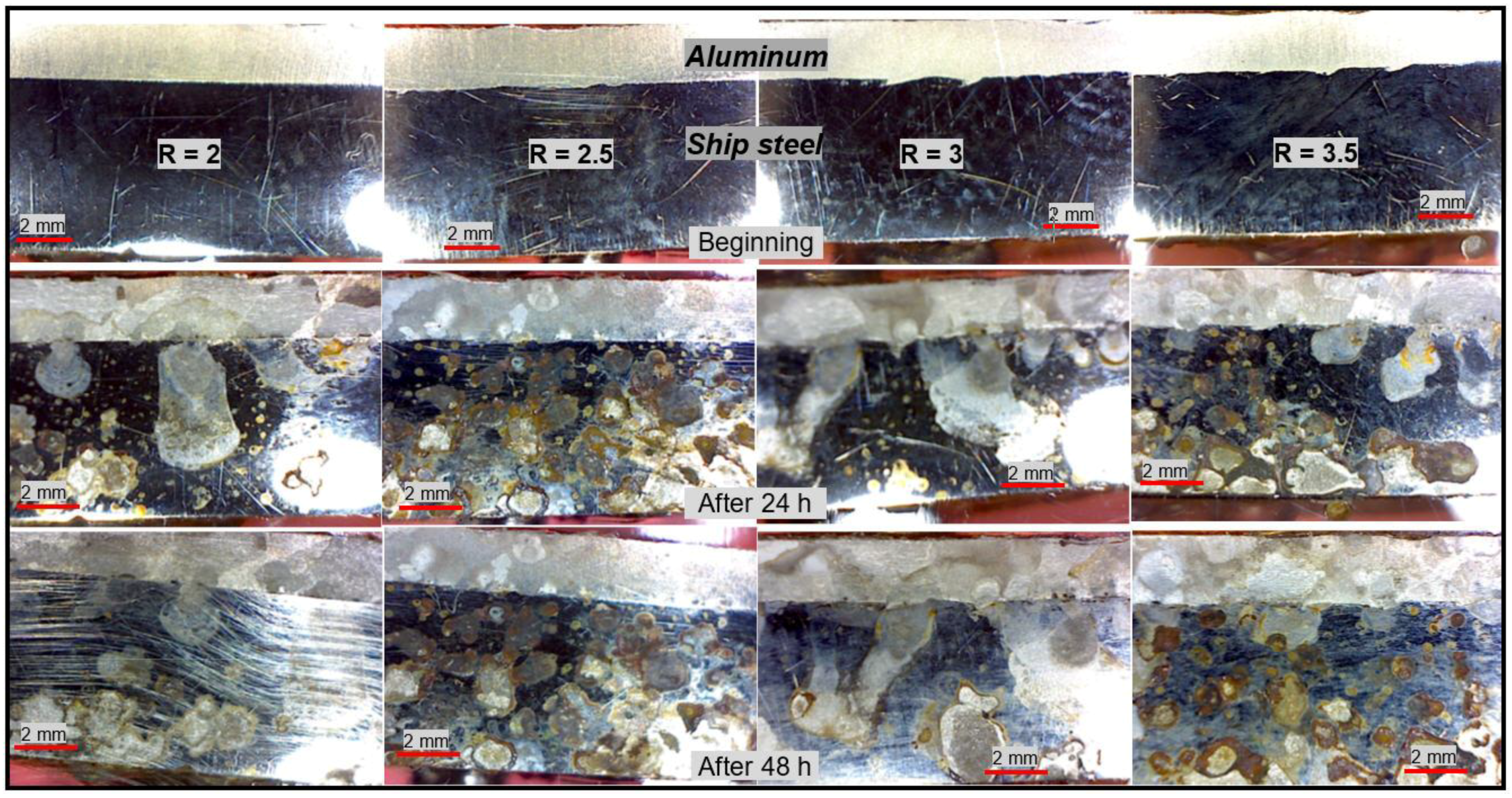
Figure 16 shows macro images of the composite samples after the NSS test performed in order to determine the corrosion behavior of the samples in seawater.
The images of the samples after the NSS tests clearly show that the ship steel had suffered corrosion due to its high chemical affinity with oxygen. After 24 h, the NSS test revealed corrosion on the ship steel side of the bimetallic composites, while corrosion was not observed on the aluminum side. After 48 h, the NSS test showed that the ship steel side of the composites was almost completely corroded, while the aluminum side still retained its corrosion resistance. It can be concluded from these NSS test results that the cladding of aluminum on top of ship steel using explosive welding protected the ship steel against corrosion in a seawater environment.
Kaya et al. [13] produced Grade A ship steel-AISI 2304 duplex stainless steel composite materials via explosive welding and applied corrosion tests (NSS and potentiodynamic polarization) to the composite specimens. The AISI 2304 was found to protect the Grade A plates against corrosion, especially in sea water.
4. Conclusions
The following conclusions were made as a result of this study investigating the microstructural, mechanical, and corrosion features of ship steel-aluminum bimetal composite materials that were produced via explosive welding at different explosive ratios:
- In the ship steel-aluminum bimetal composite samples, waving in the interface increased at increasing explosive ratios and in parallel with this, the wavelength and amplitude increased. In addition, the grains close to the bonding interface extended parallel to the explosion direction as a result of the sudden cold plastic deformation that occurred due to the pressure applied during the explosive welding. This effect gradually disappeared at distances moving further away from the interface.
- The SEM and EDS investigations on the ship steel-aluminum bimetal composite joining interface revealed that a flat interface was obtained at a low explosive ratio and no intermetallic formation was observed, but as the explosive ratio increased, a wavy structure was formed by mechanical interlocking at the interface and some intermetallic compounds (FeAl3 + αAl and α2) were formed.
- As a result of tensile-shear tests applied to the ship steel-aluminum bimetal composite samples, tensile-shear strength increased at increasing explosive ratios. In addition, no separation was present in the bonding interface of the composite samples. The SEM images of the fracture surfaces revealed ductile fractures having a matte and fibrous appearance.
- As a result of the notch impact test performed at room temperature, the impact toughness decreased due to increased deformation hardening at increasing explosive ratios. Additionally, cracking occurred in the ship steel (base plate) side of the ship steel-aluminum bimetal composites, and although bending was seen in the aluminum (cladding plate) side, no separation was present.
- The two-way bending tests performed by bending samples 180° revealed no visible cracks, fractures, or separation in the bonding interface of the bimetal composite samples that were produced at different explosive ratios.
- After the 360° twisting test was applied to the bimetal composite samples, no faults were seen in the bonding interface of any of the composites.
- The hardness test showed that the highest hardness value was measured at the bonding interface, followed by the outer surface of the plates (ship steel and aluminum) and the thick central areas of the plates. Moreover, the hardness values that were measured for the bimetal composite samples increased at increasing explosive ratios.
- As a result of salt spray tests, the aluminum cladded to the ship steel surface exhibited greater corrosion resistance when compared to that of the ship steel.
- In the microstructure studies applied to the ship steel-aluminum bimetal composite specimens, no unbonded areas were seen at the joining interface. After mechanical tests, no separation was observed at the joining interface, and after corrosion tests, no corrosion was found on the aluminum side of the joining. It can be stated that the R = 2 explosive ratio is the best choice for reducing deformation at the joining interface in the production of ship steel-aluminum bimetal composites.
Funding
This research received no external funding.
Acknowledgments
I thank the MKE Barutsan Company (Turkey) for providing explosives and facilities for explosive cladding process. This research received no external funding.
Conflicts of Interest
The author declare no conflict of interest.
References
- Kaya, Y.; Kahraman, N. An investigation into the explosive welding/cladding of grade a ship steel/AISI 316L austenitic stainless steel. Mater. Des. 2013, 52, 367–372. [Google Scholar] [CrossRef]
- Li, X.; Ma, H.; Shen, Z. Research on explosive welding of aluminum alloy to steel with dovetail grooves. Mater. Des. 2015, 87, 815–824. [Google Scholar] [CrossRef]
- Young, G.A.; Banker, J.G. Explosion welded, bi-metallic solutions to dissimilar metal joining. In Proceedings of the 13th Offshore Symposium, Houston, YX, USA, 24 February 2004; pp. 1–6. [Google Scholar]
- Koschlig, M.; Veehmayer, M.; Raabe, D. Production of steel-light metal compounds with explosive metal cladding. In Proceedings of the 3rd International Conference on High Speed Forming, Dortmund, Germany, 11–12 March 2008; pp. 23–32. [Google Scholar]
- Wang, J.M.; Zhang, Y.A. A study on weldability of aluminum alloy-aluminum-steel transition joints. Adv. Mater. Res. 2013, 631, 713–716. [Google Scholar] [CrossRef]
- Tricarico, L.; Spina, R. Experimental investigation of laser beam welding of explosion-welded steel/aluminum structural transition joints. Mater. Des. 2010, 31, 1981–1992. [Google Scholar] [CrossRef]
- Tricarico, L.; Spina, R.; Sorgente, D.; Brandizzi, M. Effects of heat treatments on mechanical properties of Fe/Al explosion-welded structural transition joints. Mater. Des. 2009, 30, 2693–2700. [Google Scholar] [CrossRef]
- Tricarico, L.; Spina, R. Mechanical strength of Fe/Al structural transition joints subject to thermal loading. Arch. Mater. Sci. Eng. 2009, 37, 85–93. [Google Scholar]
- Mousavi, S.A.A.; Barrett, L.M.; Al-Hassani, S.T.S. Explosive welding of metal plates. J. Mater. Process. Technol. 2008, 1–3, 224–239. [Google Scholar] [CrossRef]
- Guo, X.; Wang, H.; Liu, Z.; Wang, L.; Ma, F.; Tao, F. Interface and performance of clam steel/aluminum clad tube prepared by explosive bonding method. Int. J. Adv. Manuf. Technol. 2016, 82, 543–548. [Google Scholar] [CrossRef]
- Sun, X.-J.; Tao, J.; Guo, X.-Z. Bonding properties of interface in Fe/Al clad tube prepared by explosive welding. J. Trans. Nonferrous Met. Soc. China 2011, 21, 2175–2180. [Google Scholar] [CrossRef]
- Guo, X.; Tao, J.; Wang, W.; Li, H.; Wang, C. Effects of the inner mould material on the aluminium-316L stainless steel explosive clad pipe. Mater. Des. 2013, 49, 116–122. [Google Scholar] [CrossRef]
- Kaya, Y.; Kahraman, N.; Durgutlu, A.; Gülenç, B. Investigation of the microstructural, mechanical and corrosion properties of grade a ship steel-duplex stainless steel composites produced via explosive welding. Metall. Mater. Trans. A 2017, 48, 3721–3733. [Google Scholar] [CrossRef]
- Szachogluchowicz, I.; Sniezek, L.; Hutsaylyuk, W. Low cycle fatigue properties of AA2519–Ti6Al4V laminate bonded by explosion welding. Eng. Fail. Anal. 2016, 69, 77–87. [Google Scholar] [CrossRef]
- Miao, G.; Ma, H.; Shen, Z.; Yu, Y. Research on honeycomb structure explosives and double sided explosive cladding. Mater. Des. 2014, 63, 538–543. [Google Scholar] [CrossRef]
- Acarer, M.; Gülenç, B.; Fındık, F. The influence of some factors on steel/steel bonding quality on their characteristics of explosive welding joints. J. Mater. Sci. 2004, 39, 6457–6466. [Google Scholar] [CrossRef]
- Acarer, M.; Gülenç, B.; Fındık, F. Investigation of explosive welding parameters and their effects on microhardness and shear strength. Mater. Des. 2003, 24, 659–664. [Google Scholar] [CrossRef]
- Kahraman, N.; Gülenç, B.; Fındık, F. Joining of titanium/stainless steel by explosive welding and effect on interface. J. Mater. Process. Technol. 2005, 169, 127–133. [Google Scholar] [CrossRef]
- Yazdani, M.; Toroghinejad, M.R.; Hashemi, S.M. Investigation of microstructure and mechanical properties of St37 steel-Ck60 steel joints by explosive cladding. J. Mater. Eng. Perform. 2015, 24, 4032–4043. [Google Scholar] [CrossRef]
- Durgutlu, A.; Gülenç, B.; Fındık, F. Examination of copper/stainless steel joints formed by explosive welding. Mater. Des. 2005, 26, 497–507. [Google Scholar] [CrossRef]
- Chu, Q.L.; Zhang, M.; Li, J.H.; Jin, Q.; Fan, Q.Y.; Xie, W.W.; Luo, H.; Bi, Z.Y. Experimental investigation of explosion-welded Cp-Ti/Q345 bimetallic sheet filled with Cu/V based flux-cored wire. Mater. Des. 2015, 67, 606–614. [Google Scholar] [CrossRef]
- Fındık, F. Recent developments in explosive welding. Mater. Des. 2011, 32, 1081–1093. [Google Scholar] [CrossRef]
- Zhang, L.J.; Pei, Q.; Zhang, J.X.; Bi, Z.Y.; Li, P.C. Study on the microstructure and mechanical properties of explosive welded 2205/X65 bimetallic sheet. Mater. Des. 2014, 64, 462–476. [Google Scholar] [CrossRef]
- Mastanaiah, P.; Madhusudhan Reddy, G.; Satya Prasad, K.; Murthy, C.V.S. An investigation on microstructures and mechanical properties of explosive cladded C103 niobium alloy over C263 nimonic alloy. J. Mater. Process. Technol. 2014, 214, 2316–2324. [Google Scholar] [CrossRef]
- Hoseini Athar, M.M.; Tolaminejad, B. Weldability window and the effect of interface morphology on the properties of Al/Cu/Al laminated composites fabricated by explosive welding. Mater. Des. 2015, 86, 516–525. [Google Scholar] [CrossRef]
- Mazar Atabaki, M.; Nikodinovski, M.; Chenier, P.; Ma, J.; Harooni, M.; Kovacevic, R. Welding of aluminum alloys to steels: An overview. J. Manuf. Sci. Prod. 2014, 14, 59–78. [Google Scholar] [CrossRef]
- Xie, M.X.; Zhang, L.J.; Zhang, G.F.; Zhang, J.X.; Bi, Z.Y.; Li, P.C. Microstructure and mechanical properties of Cp-Ti/X65 bimetallic sheets fabricated by explosive welding and hot rolling. Mater. Des. 2015, 87, 181–197. [Google Scholar] [CrossRef]
- Asemabadi, M. Sedighi, M.; Honarpisheh, M. Investigation of cold rolling influence on the mechanical properties of explosive-welded Al/Cu bimetal. Mater. Sci. Eng. A 2012, 558, 144–149. [Google Scholar] [CrossRef]
- Loureiro, A.; Mendes, R.; Ribeiro, J.B.; Leal, M.; Galvao, I. Effect of explosive mixture on quality of explosive welds of copper to aluminium. Mater. Des. 2016, 95, 256–267. [Google Scholar] [CrossRef]
- Kaçar, R.; Acarer, M. An investigation on the explosive cladding of 316L stainless steel-DIN-P355GH steel. J. Mater. Process. Tech. 2004, 152, 91–96. [Google Scholar] [CrossRef]
- Gülenç, B.; Kaya, Y.; Durgutlu, A.; Gülenç, İ.T.; Yıldırım, M.S.; Kahraman, N. Production of wire reinforced composite materials through explosive welding. Arch. Civ. Mech. Eng. 2016, 16, 1–8. [Google Scholar] [CrossRef]
- Xia, H.B.; Wang, S.G.; Ben, H.F. Microstructure and mechanical properties of Ti/Al explosive cladding. Mater. Des. 2014, 56, 1014–1019. [Google Scholar] [CrossRef]
- Kahraman, N.; Gülenç, B.; Fındık, F. Corrosion and mechanical-microstructural aspects of dissimilar joints of Ti-6Al-4V and Al plates. Int. J. Impact Eng. 2007, 34, 1423–1432. [Google Scholar] [CrossRef]
- Wang, Y.; Beom, H.G.; Sun, M.; Lin, S. Numerical simulation of explosive welding using the material point method. Int. J. Impact Eng. 2011, 38, 51–60. [Google Scholar] [CrossRef]
- Gülenç, B. Investigation of interface properties and weldability of aluminum and copper plates by explosive welding method. Mater. Des. 2008, 29, 275–278. [Google Scholar] [CrossRef]
- Fronczek, D.M.; Wojewoda-Budka, J.; Chulist, R.; Sypien, A.; Korneva, A.; Szulc, Z.; Schell, N.; Zieba, P. Structural properties of Ti/Al clads manufactured by explosive welding and annealing. Mater. Des. 2016, 91, 80–89. [Google Scholar] [CrossRef]
- Prasanthi, T.N.; Sudha Ravikirana, C.; Saroja, S. explosive cladding and post-weld heat treatment of mild steel and titanium. Mater. Des. 2016, 93, 180–193. [Google Scholar] [CrossRef]
- Saravanan, S.; Raghukandan, K.; Hokamoto, K. Improved microstructure and mechanical properties of dissimilar explosive cladding by means of interlayer technique. Arch. Civ. Mech. Eng. 2016, 16, 563–568. [Google Scholar] [CrossRef]
Figure 1.
Parallel arrangement of experimental setup for explosive welding process (reproduced from [13], with permission from Springer, 2018).
Figure 1.
Parallel arrangement of experimental setup for explosive welding process (reproduced from [13], with permission from Springer, 2018).

Figure 2.
Schematic representation of tensile-shear test samples.

Figure 3.
Schematic representation of Charpy impact test samples.
Figure 4.
Images of bimetal composites bonding interfaces according to explosive ratios.

Figure 5.
Image of morphologies formed at bonding interface in bimetal composites.

Figure 6.
Image of grains near the bonding interface extending in the explosion direction in bimetal composites.
Figure 6.
Image of grains near the bonding interface extending in the explosion direction in bimetal composites.

Figure 7.
(a) Scanning electron microscopy (SEM) image of bimetal composite bonding interface for R = 2 and (b–d) energy dispersive spectrometry (EDS) analysis results of the indicated areas.
Figure 7.
(a) Scanning electron microscopy (SEM) image of bimetal composite bonding interface for R = 2 and (b–d) energy dispersive spectrometry (EDS) analysis results of the indicated areas.

Figure 8.
(a) SEM image of bimetal composite bonding interface for R = 2.5 and (b–d) EDS analysis results of the indicated areas.
Figure 8.
(a) SEM image of bimetal composite bonding interface for R = 2.5 and (b–d) EDS analysis results of the indicated areas.

Figure 9.
(a) SEM image of bimetal composite bonding interface for R = 3; (b) EDS analysis results of the indicated line; and, (c–e) EDS analysis results of the indicated areas.
Figure 9.
(a) SEM image of bimetal composite bonding interface for R = 3; (b) EDS analysis results of the indicated line; and, (c–e) EDS analysis results of the indicated areas.

Figure 10.
(a) SEM image of bimetal composite bonding interface for R = 3.5 and (b–d) EDS analysis results of the indicated areas.
Figure 10.
(a) SEM image of bimetal composite bonding interface for R = 3.5 and (b–d) EDS analysis results of the indicated areas.

Figure 11.
Macro images of bimetal composite samples after the tensile-shear test.

Figure 12.
Macro images of bimetal composite samples after the notch impact toughness.

Figure 13.
Macro images of bimetal composite samples after the bending test.

Figure 14.
Macro images of bimetal composite samples after the twisting test.

Figure 15.
Hardness test results of ship steel-aluminum bimetal composite samples.

Figure 16.
Macro images after the neutral salt spray test.


Table 1.
The chemical composition (wt.%) of ship steel and aluminum.
| Elements % Weight | C | Mn | Si | Al | Cu | Cr | Mg | Fe |
|---|---|---|---|---|---|---|---|---|
| Ship Steel | 0.149 | 0.7 | 0.166 | 0.028 | 0.049 | 0.022 | - | Balance |
| Aluminum | - | 0.07 | 0.61 | Balance | 0.25 | 0.097 | 0.92 | 0.20 |
Table 2.
Welding parameters.
| Explosive Type | Explosive Density (g/cm3) | Explosive Speed (ms−1) | Stand-off Distance, s (mm) | Flyer Plate Weight (g) | Explosive Ratio (R) | Explosive Amount (g) |
|---|---|---|---|---|---|---|
| Elbar-5 | 0.8 | 3000–3200 | 2 | 200 ± 5 | 2 | 400 |
| 2.5 | 500 | |||||
| 3 | 600 | |||||
| 3.5 | 700 |
Table 3.
Tensile-shear test results of bimetal composite samples.
| Tensile-Shear Strength (MPa) | ||||
|---|---|---|---|---|
| R = 2 | R = 2.5 | R = 3 | R = 3.5 | Ruptured Material |
| 28.5 ± 1 | 29.4 ± 1 | 31.5 ± 1 | 32.1 ± 1 | Aluminium |
Table 4.
Charpy impact test results of ship steel/aluminum bimetal composite.
| Charpy Impact Test (Joule) | ||||
|---|---|---|---|---|
| Ship steel/aluminum | R = 2 | R = 2.5 | R = 3 | R = 3.5 |
| 36.5 ± 1 | 35 ± 1 | 33.5 ± 1 | 33 ± 1 | |
© 2018 by the author. Licensee MDPI, Basel, Switzerland. This article is an open access article distributed under the terms and conditions of the Creative Commons Attribution (CC BY) license (http://creativecommons.org/licenses/by/4.0/).
Share and Cite
MDPI and ACS Style
Kaya, Y. Microstructural, Mechanical and Corrosion Investigations of Ship Steel-Aluminum Bimetal Composites Produced by Explosive Welding. Metals 2018, 8, 544. https://doi.org/10.3390/met8070544
AMA Style
Kaya Y. Microstructural, Mechanical and Corrosion Investigations of Ship Steel-Aluminum Bimetal Composites Produced by Explosive Welding. Metals. 2018; 8(7):544. https://doi.org/10.3390/met8070544
Chicago/Turabian StyleKaya, Yakup. 2018. "Microstructural, Mechanical and Corrosion Investigations of Ship Steel-Aluminum Bimetal Composites Produced by Explosive Welding" Metals 8, no. 7: 544. https://doi.org/10.3390/met8070544
Note that from the first issue of 2016, this journal uses article numbers instead of page numbers. See further details here.