A New Method to Recycle Stainless–Steel Duplex UNS S31803 Chips
by
 , , , , and
Mendonça Claudiney
1,* ,
,
Oliveira Adhimar
1,
Sachs Daniela
1,
Capellato Patricia
1,
Ribeiro Vander
2 ,
,
Junqueira Mateus
3,
Melo Mirian
3 and
Silva Gilbert
3 1
Institute of Physics and Chemistry, Federal University of Itajubá, Itajubá–MG 37500-903, Brazil
2
University Center of Itajubá, Itajubá–MG 37501-002, Brazil
3
Institute of Mechanical Engineering, Federal University of Itajubá, Itajubá–MG 37500-903, Brazil
*
Author to whom correspondence should be addressed.
Metals 2018, 8(7), 546; https://doi.org/10.3390/met8070546
Submission received: 25 May 2018
/
Revised: 5 July 2018
/
Accepted: 10 July 2018
/
Published: 17 July 2018
Abstract
:Due to the increased consumption of raw materials, energy, and the waste it generates, recycling has become very important and fundamental for the environment and the industrial sector. The production of duplex stainless–steel powders with the addition of vanadium carbide in the high energy mechanical milling process is a new method for recycling materials for the manufacture of components in the industrial sector. This study aims to reuse the chips from the duplex stainless–steel UNS S31803 by powder metallurgy with the addition of Vanadium carbide (VC). The mechanical milling was performed using a planetary ball mill for 50 h at a milling speed of 350 rpm and a ball-to-powder weight ratio of 20:1, and the addition of 3 wt % of VC. The material submitted to milling with an addition of carbide has a particle size of less than 140 μm. After milling, the sample went through a stress relief treatment performed at 1050 °C for 1 h and the isostatic compaction process loaded with 300 MPa. The sintered powders and material was characterized by scanning electron microscopy, X-ray diffraction, and micro-hardness tests. The milling process with an addition of 3% VC produced a particle size smaller than the initial chip size. The measurement of micrometric sizes obtained was between 26 and 132 μm. The sintered material had a measurement of porosity evaluated at 15%. The obtained density of the material was 84% compared to the initial density of the material as stainless–steel duplex UNS S31803. The value of the microhardness measurement was 232 HV. The material submitted for grinding presented the formation of a martensitic structure and after the thermal treatment, the presence of ferrite and austenite phases was observed. Thus, in conclusion, this study demonstrates the efficacy in the production of a metal-ceramic composite using a new method to recycle stainless–steel duplex UNS S31803 chips.
1. Introduction
Nowadays, a great motivation for metal research is developing ways to optimize steel for the property of application through cost-effective processing routes [1]. In the stainless–steel family, the stainless–steel duplex UNS S31803 has been widely used in many industrial sectors because of its surface physicochemical properties and resistance to corrosion, abrasion and antioxidation [2,3]. Duplex stainless–steels are steels in which the microstructure consists of two main phases: austenite (y-FCC) and ferrite (α-BCC) in equal proportions, which can combine the good properties of the ferritic and austenitic phases [3,4,5,6].
The conventional manufacturing processes of duplex SS are complex and high-cost. However, the powder metallurgy process, which is a near net shaping process with reduced processing costs, is attractive for the production of duplex SS [7]. Grupta et al. (2015) performed a simulation and experimental study of the synthesis of duplex stainless–steel nano-structures using planetary milling with powder composition for Fe-Ni-Cr elements [8]. Tański et al. (2014) obtained a duplex microstructure and a balance between phases with the addition of alloying element powders such as Cr, Ni, Mo, and Cu, in the planetary mill. They found that the sintering process at 1250 °C followed by rapid cooling generated a mixed grain duplex microstructure and a phase balance [9]. Dobrzánski et al. (2007) used a tubular mixer to correct the chemical composition of the duplex stainless–steel through a blend of powders using an austenitic steel (Fe-17 Cr-13Ni-2.2Mo) composition with elementary Si, Mn and Cu powders in order to correct the composition [10]. On the other hand, Shashanka & Chaira (2015) utilized the Fritsch planetary mill to develop a duplex ferritic stainless–steel starting from a blend of high purity Fe-Cr-Ni powders. Finally, they sintered all the samples at 1000 °C, 1200 °C and 1400 °C [11]. Garcia et al. (2012) studied a duplex stainless–steel by mixing powders of AISI 316 L austenitic steel and AISI 430L ferritic with the percentage of AISI 316L being adjusted to 25, 50, and 75% by weight. The samples were compacted at 750 MPa and sintered at 1250 °C [12].
The increase in the costs of raw materials and energy in recent years has led to the development of new methods to reuse machining chips as raw material for the production of mechanical components. The reuse of recyclable materials has as its main objectives the minimization of environmental impacts and the decrease of energy supply. The powder metallurgy route is an advantageous technique as 95% of the machined metal chips can be recovered [13]. Also, Canakci and Varol (2015) investigated the milling process using used chips of aluminum 7075 to obtain powder with particle sizes smaller than the initial chip size [14].
The powder metallurgy (PM) process has four stages: pulverization of scrap, mixing, compaction to the shape of the final product and sintering. Methods like ball milling, target jet milling and high-energy ball milling are used for pulverization of this scrap [15]. High-energy ball milling has been used to improve particle distribution throughout the matrix and to produce a powder with irregular shape and size [15,16,17]. Mechanical milling (MM) is characterized by frequent impulses created by balls that introduce a high value of mechanical energy and strain. It results in work hardening and the fracture of the particulates into smaller powder particles [14,18]. It is also a commonly used solid-state powder processing technique involving repeated mechanical welding, fracturing, and rewelding of powder particles in a high-energy ball mill [14,18,19,20,21].
The high plastic deformation induced in the duplex stainless–steel by high-energy ball milling produces the formation of the martensitic phase. The deformation-induced martensitic transformation phase is formed in an austenitic structure [22,23,24,25]. Oleszak et al. (2007) produced austenitic stainless–steel powder using a Fritsch planetary mill. These authors verified the formation of both austenitic and martensitic phases in stainless–steel structures [26]. Mendonça et al. (2017) in preview studies verified the formation of martensitic phase induced by deformation in the milling of chips of duplex stainless–steel UNS S31803 after 50 h [22].
Metal matrix composites (MMCs) are used to improve the mechanical properties of steels produced by powder metallurgy because the addition of carbides as reinforcement is advantageous [27]. The MMCs has at least two constituent parts: a metal and another material or a different metal, reinforced with micro-sized ceramic/oxide in the shape of fibers or particles [28,29,30]. This fabrication procedure allows for an acceptable uniform dispersion of reinforcing particles in a metallic matrix [31]. The manufacturing of MMCs by powder metallurgy offers some advantages compared with ingot metallurgy or diffusion welding, such relatively low processing temperatures avoid strong interfacial reactions and minimize an undesired reaction between the matrix and the reinforcement [32,33]. The P/M process usually involves the mixing of powders of the matrix alloy with the reinforcing particles, followed by compacting and solid-state sintering [32]. Metal carbides have important properties such as high temperature stability, high hardness and good electrical and thermal conductivity [34,35]. The addition of these carbides has also been shown to improve the efficiency of the milling process. Kufffer et al. (2015) studied the addition of niobium carbide in the high-energy milling of a 52,100 steel causes an increase in the efficiency of the milling process with a greater reduction of particle size compared to carbide-free milling [36]. Dias et al. (2018) added carbides which resulted in increased efficiency of the high energy milling process used in the recycling of aluminum bronze alloy chips [37].
The aim of the present work was to evaluate a new method to recycle stainless–steel duplex UNS S31803 chips. Thus, the result is to obtain reducing the cost of manufacturing in the industrial sector and recycling the materials discarded in the machining process. In this study, was evaluated the feasibility of reusing the UNS S31803 duplex stainless–steel chip by high-energy milling with the addition of vanadium carbide. Also, the isostatic press was utilized to produce a metal-ceramic composite. The obtained composite was investigated using scanning electron microscopy, X-ray diffraction, and micro-hardness tests.
2. Materials and Methods
The raw material in the form of chips used in the high-energy milling process was obtained by machining sheet metal of a duplex stainless–steel UNS S31803 with low rotation and no use of lubricants, thus avoiding contamination with soluble oil. The average size of the chips was characterized by binocular stereoscopic microscopy (Model Olympus SZ61, Tokyo, Japan). For the milling, 3 wt. % VC with an initial size between 5 μm and 10 μm was added in a high energy mill of the Noah-Nuoya model NQM 0.2 L (Yangzhou Nuoya Machinery CO., LTD, Yangzhou, Hanjiang District, China), the speed was 350 rpm, mass/ball ratio of 1:20 and milling time of 50 h with argon atmosphere to avoid the oxidation of the powders. After milling, a pre-grading was carried out through a 300 μm sieve. A particle size analyzer (Microtrac model S3500, Microtrac Global Location, Montgomeryville, PA, USA) was used to collect the particle sizes and their distribution. The characterization of the obtained powders was carried out using a scanning electron microscope—Carl Zeiss EVO MA 15 (ZEISS Microscopy, Cambridge, UK)—in the secondary electron mode (SE), backscatter and energy dispersion (EDS). The sample was polished with colloidal silica before microstructural analysis.
Thereafter, a stress relief treatment was performed at 1050 °C for 30 min on the furnace. The samples were quenched in water. For the compaction process, the powder was submitted initially to the uniaxial press (SCHULZ-Mod. 30T, Joinville, Brazil) at a load of 300 MPa to mold the initial body. After that, the samples were subjected to isostatic at compaction (model WT Industria, São Carlos, Brazil). Then, the samples were wrapped with latex in a vacuum environment (10−1 mbar). The pressing process was done at room temperature in three steps. In the first step, the samples were allowed to stand for 5 min at 150 MPa pressure, then 250 MPa for 5 min and finally at 350 MPa for 20 min. Samples were placed in one oil-encased chamber. So, a uniformly distributed load was applied. The samples were sintered in a vacuum muffle (Fortelab, São Carlos, Brazil) resistive furnace for 1 h at 1250 °C with a rated heating of 5 °C/min and they are left to cool in the furnace.
The identification of the phases in the microstructure was made using the X-ray diffraction technique (PANalytical X'Pert Pro model B.V., Almelo, The Netherlands).The parameters used were: scan angle from 45 to 135°, a pitch of 0.02°/s, and cobalt tube (λ = 1.7890 A°). For the conditions as received, and sintered, 10 measurements of Vickers microhardness with a load of 50 gf were carried out in a Micro-hardness, Tester HV 1000 of the Digimess (São Paulo, Brazil). The dwelling time of the micro-hardness test is 15 s. In order to do the analysis of the grain boundaries, the samples were sanded, polished and subjected to an electrolytic attack at 5 V for 10 s with the oxalic reagent.
The green density of the samples was obtained by mass/volume ratio. The density after sintering was taken by mass/volume ratio—and also by the Archimedes principle—according to the ASTM STANDARD C 20 [38]. For the determination of the percent porosity in the sintered samples, five images of each sample were taken and an average was calculated. The images obtained by Optical microscopy were analyzed with the (Stream Basics 1.9.1. software, Olympus, Waltham, MA, USA).
3. Results and Discussion
Figure 1 shows the initial characterization of UNS S31803 steel chips obtained by machining. Basically, chip formation is a shear process involving plastic deformation within the shear zone [14,39]. The encircled region in Figure 1 shows the shear area of a particle caused by plastic deformation. This process produced helical-shaped chips. It is observed that the obtained chips have an average size of 8 mm. Figure 2 shows an enlargement of the regions of plastic deformation resulting from the shear caused by the machining.
Figure 3 shows the particle morphology obtained by SEM after high-energy milling with the addition of 3% vanadium carbide, the chip-shaped material was transformed into particles with irregular morphology and heterogeneous size, ranging from 10 to 150 μm. The material submitted to milling with the addition of carbide has a particle size of fewer than 140 μm and an average size of 67.42 μm.
Thus, the particle size obtained after 50 h of milling with 3% vanadium carbide was the measurement by particle size analyzer and was found to be smaller than the initial chip size. Mendonça et al. (2017) show that the addition of carbides increases the efficiency of the milling process over carbide-free milling—this is due to the carbide particles, a material with a high hardness, which collides with the chip. This collision causes a region of generalized stresses in the ductile particle, leading to rupture through the combination of the ductile-brittle process [40].
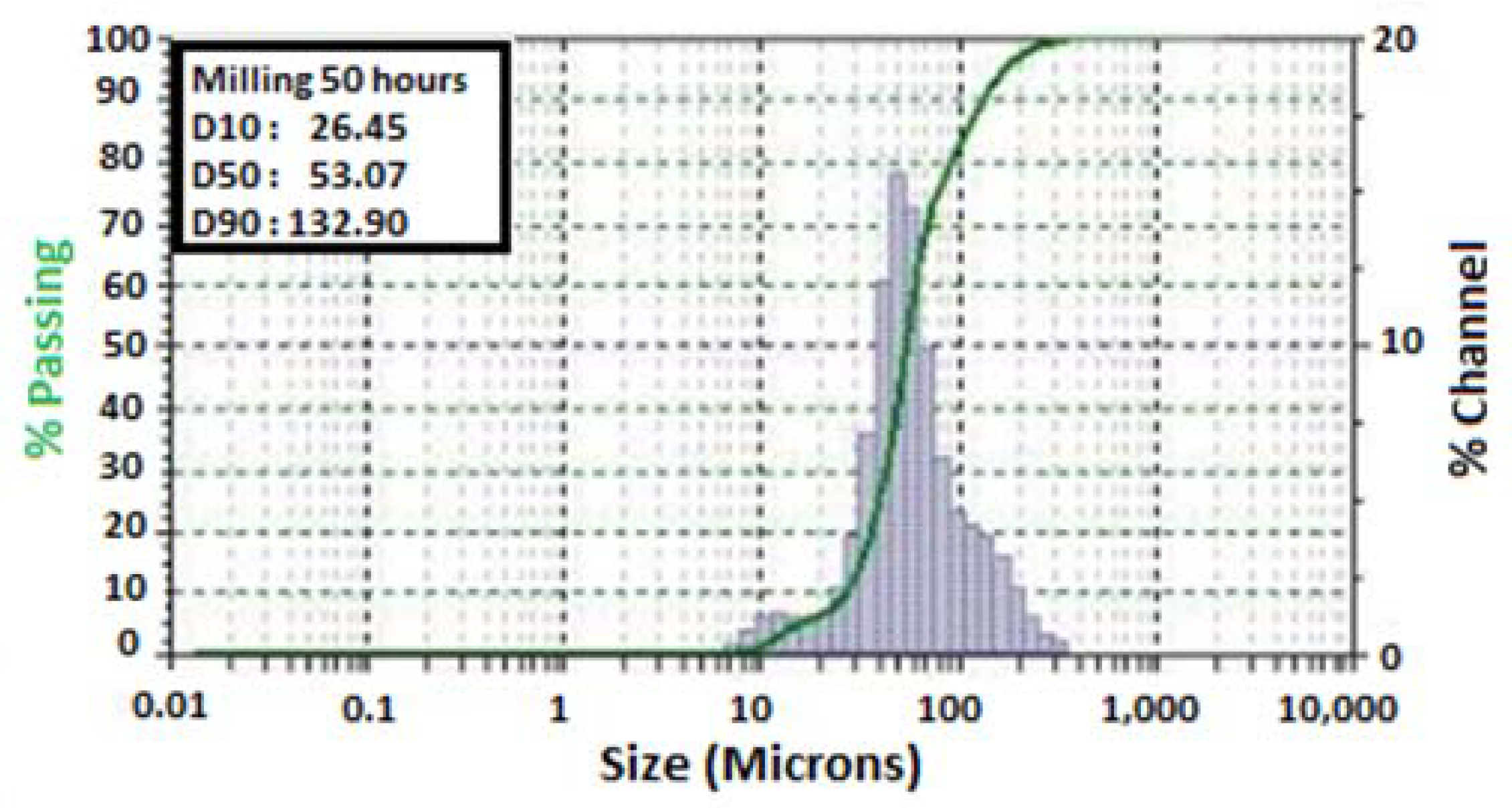
Figure 4 shows the particle size analysis, which reveals a distribution region with sizes between 20 and 200 μm. Analyzing the graph, the particle size for the D50 factor with VC was 53.07 μm with 50 h milling, which indicates that 50% of the particles have up to this size. Likewise, the reported values for D10 and D90 are 26.45 μm and 132.90 μm, indicating that 10% of particles have dimensions less than 26.45 μm and 90% of particles are below the size of 132.9 μm, respectively.
Table 1 shows the average green densities which were 5.08 g/cm³. Also, the value measurement by the Archimedes method after the sintering. After sintering, it was verified with the Archimedes method that the average density of the samples produced with adding 3% vanadium carbide was 6.57 g/cm³. It is 16% lower than that of the steel produced by the melting process with the average density was 7.8 g/cm³. Shashanka et al. (2015) verified an increase in density values for the duplex stainless–steels starting from Fe-Cr-Ni powders produced by powder metallurgy at temperatures of 1000 °C, 1200 °C and 1400 °C. These authors found the highest values of sintered density to ferritic stainless–steel at 89% to 1400 °C following for 1200 °C with 83% of sintered density [11].
Figure 5 shows the micrograph of the sintered sample at 1250 °C for 1 h. Furthermore, it verified the presence of uniform pore shapes distributed in the microstructure. The pores have dimensions ranging from 3 to 20 μm. The porosity is related to the particle size distribution. This facilitates atomic diffusion and densification at the moment of sintering and resulting in a microstructure with a lower porosity. However, in this study, the obtained porosity increased, although the process presented a good distribution.
Abdoli et al. (2009) [41] performed the milling of Al-X wt % AlN (X = 0, 2.5, 5 and 10) composite powders in a planetary ball mill for 25 h. They found the sinterability was degraded when increasing the reinforcement content material. Due to a decrease in the compressibility and green density of the composite when increasing the amount of reinforcing material because this causes less metal-to-metal contact.
Varol and Canakci (2013) [42] investigated the effects of weight percentage and particle size of B4C reinforcements on the physical and mechanical properties of powder metallurgy Al2024-B4C composites. Based on their study, the relative density decreased with increasing amounts of B4C particles in the consolidated samples. They have more corrosion in the regions with pores.
Figure 6a shows the distribution of vanadium particles on the stainless–steel particles. It was observed that the vanadium particles are located in both the matrix and the pores. Figure 6b identified the particles using EDS. It shows the presence of a vanadium chemical element, as well as the presence of iron, chromium and nickel elements, which are constituent elements of duplex stainless–steel. In this study, the temperature used was 1250 °C, which is below the melting temperature of the vanadium carbide of 2800 °C so that the dissociation of carbon and vanadium elements does not occur. Figure 6a shows the presence of the vanadium carbide on green color in the pores. The presence of carbide on the surface of the particles makes the contact between the metal-metal particles impossible at the moment of compaction. This situation then hinders the atomic diffusion process. Due to the impacts generated in the milling process, a decrease in the size of the carbide can be observed, with particles having sizes smaller than 1 μm.
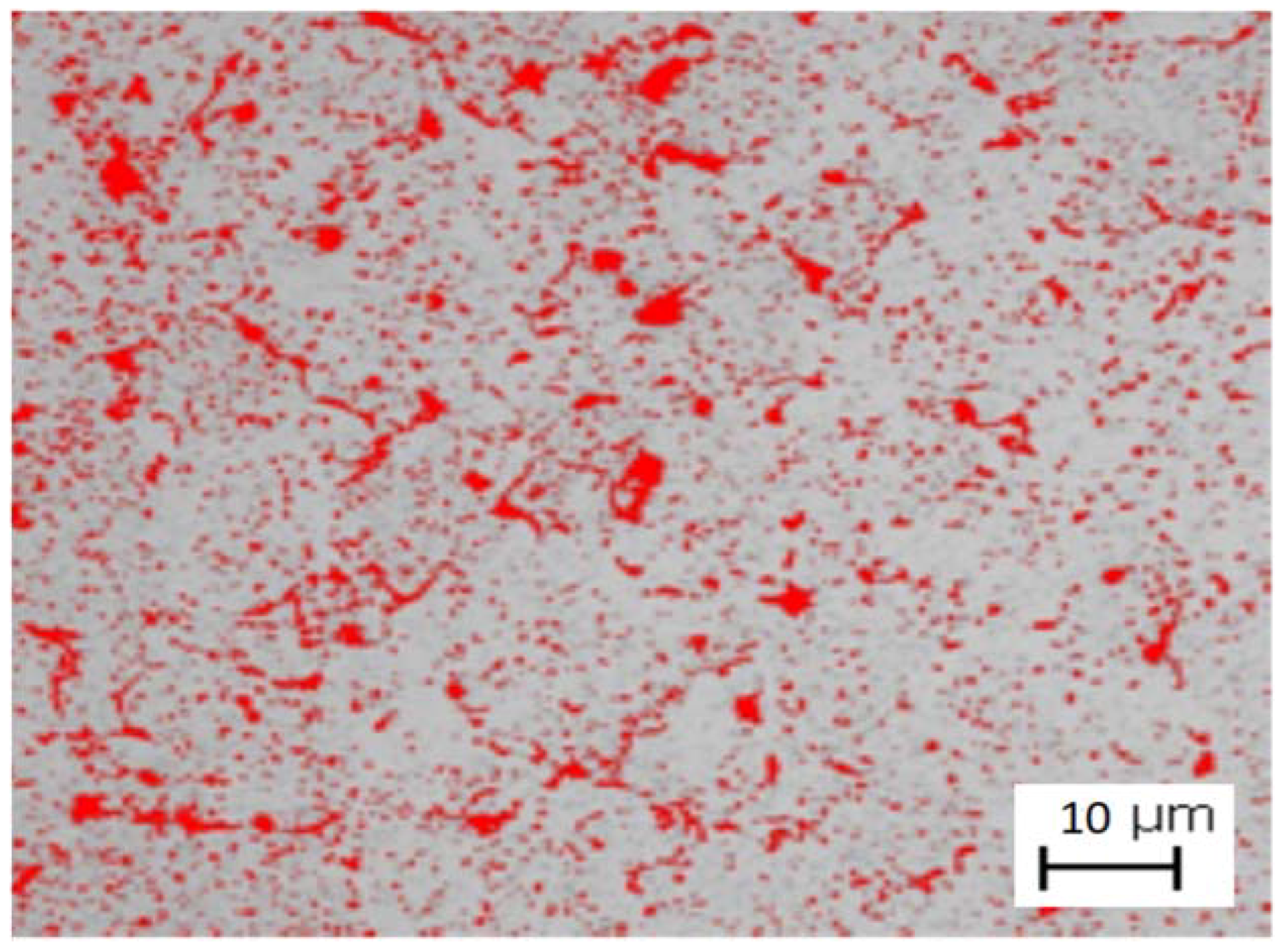
Figure 7 shows the micrograph of the sample of stainless–steel compacted in the isostatic press and then sintered at 1250 °C. In order to obtain an average of the samples, five images obtained by optical microscopy were analyzed. In these images, 15% of porosity on sintered samples could be observed.
In Figure 7, the red spots represent the pores, while the white spots represent the sintered duplex stainless–steel. As reported above, at the moment of the compaction and sintering process, if this ceramic is between two particles, it hinders the diffusion process of the samples, leading to an increase in porosity.
The microstructure analysis in Figure 8 shows images of duplex stainless–steel samples sintering at 1250 °C. The grain contours can be observed in regions with larger particles. The presence of pores with dimensions between 5 and 40 μm is identified and the presence of grain with an average size of 20 μm is observed inside the particles.
In Table 2 it is observed that the values of microhardness in the steel as received decreased from 284.16 HV0.05 to 232.02 HV0.05 for the sample subjected to milling with the addition of 3% VC and is sintered to 1250 °C. The decrease in the microhardness of the sintered sample in relation to the sample of the material as received is probably due to the presence of pores in the sintered sample and the bad atomic diffusion that occurred during the sintering at 1250 °C. The hardness value obtained was 87% compared to the sample as received and it was verified that the carbides help in the milling process, increasing the process efficiency but reducing the hardness values, being related to the presence of pores and not to the dissociation of these matrix elements, which is concentrated in regions with pores.
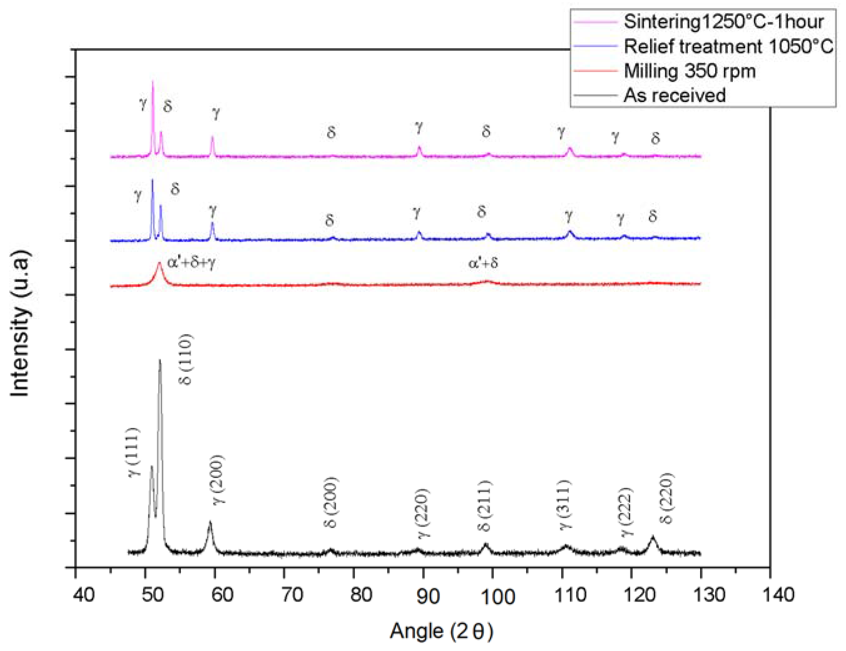
Figure 9 shows the X-ray diffractogram under the following conditions: material as received, 50 h milled material after the tension relief treatment process, and the sintered material at 1250 °C. Note that X-ray diffraction peaks are enlarged due to the decrease in particle size, due to the intense plastic deformation that occurs during high-energy milling [43] as well as the high density of dislocations due to the high degree of deformation imposed by the process [16]. During milling, different processes such as structural defects, amorphization and reduction in grain size occur and this results in the broadening of diffraction peaks [11]. It can be seen in the diffractogram of Figure 8 that after the milling process, there was a decrease in the intensity and the broadening of the peaks of the ferritic (110) and austenitic (111) phase. Note also the disappearance of the peaks of the austenite phase (200), (200), (311) and (222) and the relative peak intensity of the ferrite (220). The presence of deformation-induced martensite was also observed. Mendonça et al. (2017) verified the appearance of the martensite induced by deformation after the milling process, by increasing the values of saturation magnetization obtained by magnetic measurements [22].
The material was subjected to the stress-relief treatment at 1050 °C in the vacuum. After this process ferritic and austenitic phases could be observed. The presence of the 3% vanadium carbide was not observed on X-rays because it is below the detection limit of the apparatus.
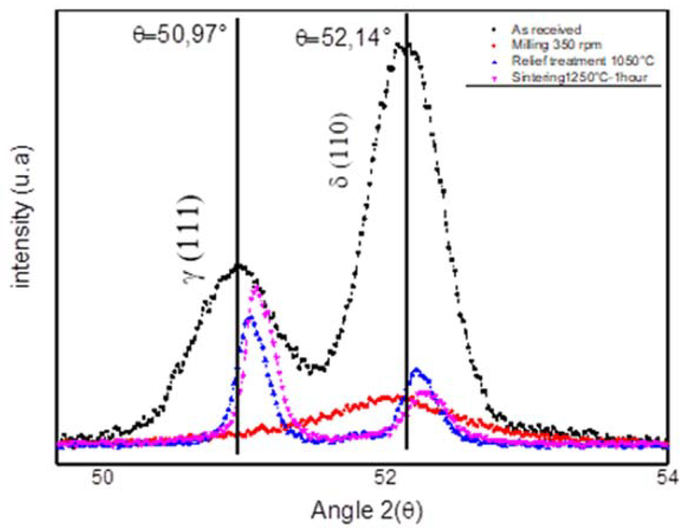
Moreover, it can be seen in the diffractogram in Figure 10, in the regions of angles between 50° and 54°, that after the milling process there was a decrease in the intensity and the broadening of the peaks of the ferritic (110) and austenitic (111) phase, compared to the material as received (in the form of a sheet), this occurs due to the non-uniform plastic deformation (microtension) of the crystal line lattice resulting from the stacking faults, among other crystalline defects resulting from the grinding process and the reduction of particle size [44].
After heat treatment, there is a decrease in the width of the phase peaks and also an increase in the height of the phases. This behavior is associated with the reduction of micro-tensions caused by annealing. After the process of stress relief and sintering, the presence of the ferrite phase and the austenite phase is observed. The presence of the martensitic phase was not observed after the heat treatment process. The deformation of martensite induced is not stable at high temperatures and the reversion of martensite to austenite occurs by soaking at elevated temperatures [45,46,47,48]. Moallemi et al. (2017) [49] realized the cold rolling-reversion annealing was carried out at various temperatures in the range of 750–1100 °C. These authors verified that there was an increase in the reversion of the martensite fraction with the increase in temperature and a complete reversal occurred at 1050 °C. For the austenitic steels of the 304 family the total martensite reversion occurred at 750 °C [50].
Figure 10 shows a peak shift to the right for the ferrite phase (110) in the angle 52.14° for the treatment of tension relief of 0.08° and 0.12° after sintering and also a displacement of 0.09 after the stress relief treatment and 0.14° after sintering for the austenitic (111) phase, which characterizes the displacement of crystalline planes of the material after the sintering process.
In the industrial sequence for obtaining duplex stainless–steel by rolling includes two annealing steps: one intermediate after the hot rolling and the final one after the cold rolling [51,52]. In most applications, the duplex structures are manufactured from hot-rolled and annealed sheets. For this reason, its crystallographic texture results from the phenomena of deformation, recrystallization and phase transformation that occur in the austenite and ferrite phases [52,53]. These higher values obtained for phase quantification for the material as received (in the form of sheets) could be related to the crystallographic texture obtained in the processing of the material.
Likewise, Figure 10 exhibits an inversion of the intensity of the austenite peaks compared to that of the ferrite for the treatment carried out at 1050 °C. It can also be observed as an increase in the volumetric fraction of the austenite phase, the quantification value obtained by X-rays was 54% of austenite and 46% of ferrite. When the solution-treatment temperature is above 1050 °C but below the solvus line there is a progressive increase in ferrite content [54]. Gholami et al. (2015) [55] verified an increase in the amount of ferrite phase with increasing temperature of annealing. The volume fraction of ferrite for solution annealed at 1050 °C is 42% and increases to 52% and 69% for the sample solution annealed at 1150 °C and 1250 °C respectively. According to these authors, this phenomenon can be appropriately described by means of phase transformation diagrams [54,55].
The DSS is completely ferritic (δ) and the cooling of the steel enhances the precipitation of austenite at a temperature of 1300 °C [56]. On the other hand, fast water cooling can avoid the δ → γ. Then, in the sample sintering at 1250 °C and the sample being cooled to the furnace, a larger amount of austenitic phase may have occurred. Also, the formation of a larger amount of austenitic phase occurred in the sample submitted to the sintering treatment at 1250 °C and the sample cooled to the furnace.
4. Conclusions
In this study, the results indicated that the powders obtained from the high energy ball mill exhibited a high volume of particles in the sub-micrometric scale. The milling process, with an addition of 3% VC, produced a particle size smaller than the initial chip size. The measurement of micrometric sizes obtained were between 26 and 132 μm. Due to the decrease in particle size, the network deformation and the intense plastic deformation, the X-rays diffraction peaks are enlarged after the high energy milling process. Diffractograms of the material subjected to the stress relief treatment at 1050 °C and sintering to temperature 1250 °C show the appearance of the ferritic, and the austenitic. Also, the peaks of the martensitic phase are observed only on samples submitted after the milling process and with no presence after treatment at 1050 °C.
The sintered material has a measurement of porosity evaluated at 15%. The obtained density of the material was 84% compared to the density of the material as stainless–steel duplex UNS S31803 received. The value of the microhardness measurement was 232 HV. It is 13% exponentially less then stainless–steel duplex UNS S31803 received. The decrease in hardness and the increase in porosity values are related to the presence of the carbide on the surface of the particles making impossible contact between the metal-metal particles at the moment of compaction.
The milling process is an alternative route to reuse the UNS S31803 duplex stainless–steel chip. In addition, it allows for the production of duplex stainless–steel powders with vanadium carbide for the manufacture of parts in the industry, through the recycled material.
Thus, in conclusion, this study demonstrates the efficacy in the production of the metal-ceramic composite of a new method for recycling stainless–steel duplex UNS S31803 chips.
Author Contributions
Conceptualization, M.C., O.A. and S.G.; Methodology, M.M. and M.C.; Formal Analysis, M.C., C.P., J.M., R.V. and S.G.; Investigation, O.A., R.V.; Writing-Review & Editing, M.C., C.P., O.A., J.M. and S.G.; Supervision, S.D., M.M. and S.G.
Acknowledgments
The authors thank the Brazilian agencies, CAPES, CNPq and FAPEMIG, for their financial support.
Conflicts of Interest
The authors declare no conflict of interest.
References
- Tranchida, G.; Clesi, M.; Di Franco, F.; Di Quarto, F.; Santamaria, M. Electronic properties and corrosion resistance of passive films on austenitic and duplex stainless–steels. Electrochim. Acta 2018, 273, 412–423. [Google Scholar] [CrossRef]
- Sheikhzadeh, M.; Sanjabi, S. Structural characterization of stainless–steel/TiC nanocomposites produced by high-energy ball-milling method at different milling times. Mater. Des. 2012, 39, 366–372. [Google Scholar] [CrossRef]
- Shashanka, R.; Chaira, D. Optimization of milling parameters for the synthesis of nano-structured duplex and ferritic stainless–steel powders by high energy planetary milling. Powder Technol. 2015, 278, 35–45. [Google Scholar] [CrossRef]
- Gunn, R.N. Duplex Stainless–Steels: Microstructures, Properties and Applications, 2nd ed.; Woodlhead Publishing: Cambridge, UK, 2003. [Google Scholar]
- Fréchard, S.; Martin, F.; Clément, C.; Cousty, J. AFM and EBSD combined studies of plastic deformation in a duplex stainless–steel. Mater. Sci. Eng. A. 2006, 418, 312–319. [Google Scholar] [CrossRef]
- Cabrera, J.M.; Mateo, A.; Llanes, L.; Prado, J.M.; Anglada, M. Hot deformation of duplex stain-less steels. J. Mater. Process. Technol. 2003, 143, 321–323. [Google Scholar] [CrossRef]
- Brytan, Z.; Dobrzánski, L.A.; Actis Grande, M.; ROSSO, M. The influence of sintering time on the properties of PM duplex stainless–steel. J. Achiev. Mater. Manuf. Eng. 2009, 37, 387–396. [Google Scholar]
- Grupta, S.; Shashanka, R.; Chaira, D. Synthesis of nano-structured duplex and ferritic stainless–steel powders by planetary milling: An experimental and simulation study. IOP Conf. Ser. Mater. Sci. Eng. 2015, 75, 01203. [Google Scholar]
- Tański, T.; Labisz, K.; Brytan, Z. Fatigue behaviour of sintered duplex stainless–steel. Procedia Eng. 2014, 74, 421–428. [Google Scholar] [CrossRef]
- Dobrzánski, L.A.; Brytan, L.A.; Actis Grande, Z.M.; Rosso, M. Corrosion resistance of sintered duplex stainless–steels in the salt fog spray test. J. Mater. Process. Technol. 2007, 192, 443–448. [Google Scholar] [CrossRef]
- Shashanka, R.; Chaira, R.D. Development of nano-structured duplex and ferritic stainless–steels by pulverisette planetary milling followed by pressureless sintering. Mater. Character. 2015, 99, 220–229. [Google Scholar]
- Garcia, C.; Martin, F.; Blanco, Y. Effect of sintering cooling rate on corrosion resistance of powder metallurgy austenitic, ferritic and duplex stainless–steels sintered in nitrogen. Corros. Sci. 2012, 61, 45–52. [Google Scholar] [CrossRef]
- Gronnostajski, J.; Chmura, W.; Gronostajski, Z. Phases created during diffusion bonding of aluminum and aluminum bronze chips. J. Achiev. Mater. Manuf. Eng. 2006, 19, 32–37. [Google Scholar]
- Canakci, A.; Varol, T. A novel method for the production of metal powders without conventional atomization process. J. Clean. Prod. 2015, 99, 312–319. [Google Scholar] [CrossRef]
- Rane, K.K.; Date, P.P. Sustainable Recycling of Ferrous Metallic Scrap Using Powder Metallurgy Process. J. Sustain. Metall. 2017, 3, 251–264. [Google Scholar] [CrossRef]
- Fogagnolo, J.B.; Velasco, F.; Robert, M.H.; Torralba, J.M. Effect of mechanical alloying on the morphology, microstructure and properties of aluminium matrix composite powders. Mater. Sci. Eng. A 2003, 342, 131–143. [Google Scholar] [CrossRef]
- Costa, C.E.; Zapata, W.C.; Parucker, M.L. Characterization of casting iron powder from recycled swarf. J. Mater. Process. Technol. 2003, 143–144, 138–143. [Google Scholar] [CrossRef]
- Suryanarayana, C. Mechanical alloying and milling. Prog. Mater. Sci. 2001, 46, 1–184. [Google Scholar] [CrossRef]
- Afkham, Y.; Khosroshahi, R.A.; Kheirifard, R.; Mousavian, R.T.; Brabazon, D. Microstructure and morphological study of ballmilled metal matrix nanocomposites. Phys. Met. Metallogr. 2017, 118, 749–758. [Google Scholar] [CrossRef]
- Ehteshamzadeh, M.A.; Mousavian, R.T. Fabrication of an r-Al2Ti intermetallic matrix composite reinforced with α-Al2O3 ceramic by discontinuous mechanical milling for thermite reaction. Int. J. Miner. Metall. Mater. 2014, 21, 1037–1043. [Google Scholar]
- Afkham, Y.; Khosroshahi, R.A.; Mousavian, R.T.; Brabazon, D.; Kheirifard, R. Microstructural characterization of ball-milled metal matrix nanocomposites (Cr, Ni, Ti)-25 wt % (Al2O3np, SiCnp). Particulate Sci. Technol. 2018, 36, 72–83. [Google Scholar] [CrossRef]
- Mendonça, C.S.P.; Dias, A.N.O.; Melo, M.L.N.M.; Ribeiro, V.A.S.; Da Silva, M.R.; Oliveira, A.F.; Silva, G. Evaluation of high-energy milling efficiency in stainless–steel with addition of vanadium carbides. Int. J. Adv. Manuf. Technol. 2018, 95, 3093–3099. [Google Scholar] [CrossRef]
- Baldo, S.; Mészáros, I. Effect of cold rolling on microstructure and magnetic properties in a metastable lean duplex stainless–steel. J. Mater. Sci. 2010, 45, 5339–5534. [Google Scholar] [CrossRef]
- Tavares, S.S.M.; Silva, M.R.; Pardal, J.M.; Abreu, H.F.H.; Gomes, A.M. Microstructural changes produced by plastic deformation in the UNS S31803 duplex stainless–steel. J. Mater. Technol. 2006, 180, 318–322. [Google Scholar] [CrossRef]
- Zhang, H.; Zhao, Y.; Wang, Y.; Yu, H.; Zhang, C. Fabrication of nanostructure in inner-surface of AISI 304 stainless–steel pipe with surface plastic deformation. J. Mater. Sci. Technol. 2018, in press. [Google Scholar] [CrossRef]
- Oleszak, D.; Grabias, A.; Pekala, M.; Swiderska-Sroda, A.; Kulik, T. Evolution of structure in austenitic steel powders during ball milling and subsequent sintering. J. Alloy. Compd. 2007, 434–435, 340–343. [Google Scholar] [CrossRef]
- Trueman, A.R.; Schweinsberg, D.P.; Hope, G.A. A study of the effect of cobalt additions on the corrosion of tungsten carbide/carbon steel metal matrix composites. Corros. Sci. 1999, 41, 1377–1389. [Google Scholar] [CrossRef]
- Pramanik, A.; Basak, A.K.; Dong, Y.; Shankar, S.; Littlefair, G. Milling of nanoparticles reinforced Al-based metal matrix composites. J. Compos. Sci. 2018, 2, 13. [Google Scholar] [CrossRef]
- Vijaya, M.; Srinivas, K. Development and Mechanical Properties of SiC Reinforced Aluminium Metal Matrix Composites. J. Recent Act. Prod. 2018, 3, 1–9. [Google Scholar]
- Lynch, C.T.; Kershaw, J.P. Metal Matrix Composites; CRC Press: Boca Raton, FL, USA, 2018. [Google Scholar]
- Śusniak, M.; Karwan-baczewska, J.; Dutiewicz, J.; Actis Grange, M.; Rosso, M. Structure investigation of ball milled composite powder based on AlSi5Cu2 alloy chips modified by SiC particles. Arch. Metall. Mater. 2013, 58, 437–441. [Google Scholar]
- Torralba, J.M.; Da Costa, C.E.; Velasco, F. P/M aluminum matrix composites: An overview. J. Mater. Process. Technol. 2013, 133, 203–206. [Google Scholar] [CrossRef]
- Śusniak, M.; Karwan-Baczewska, J.; Dutkiewicz, J.; Actis Grande, M.; Rosso, M. An experimental study of aluminum alloy matrix composite reinforced sic made by hot pressing method. Arch. Metall. Mater. 2015, 60, 1523–1527. [Google Scholar] [CrossRef]
- Gubernat, A.; Zych, L. The isothermal sintering of the single-phase non stoichiometric niobium carbide (NbC1−x) and tantalum carbide (TaC1−x). J. Eur. Ceram. Soc. 2014, 34, 2885–2894. [Google Scholar] [CrossRef]
- Kosolapova, T.Y. Carbides Properties, Production and Applications; Springer Publishing: New York, NY, USA, 1971. [Google Scholar]
- Kuffner, B.H.B.; Diogo, W.S.; Amancio, D.A.; Rodrigues, G.; Silva, G. Evaluation of the milling efficiency increase of AISI 52100 steel using niobium carbide addition through high energy ball milling. Rem: Revista Escola de Minas 2015, 68, 295–300. [Google Scholar] [CrossRef] [Green Version]
- Dias, A.N.O.; Oliveira, L.A.; Mendonça, C.S.P.; Junqueira, M.M.; Melo, M.L.N.M.; Silva, G. Comparative analysis of niobium and vanadium carbide efficiency in the high energy mechanical milling of aluminum bronze alloy. REM Int. Eng. J. 2018, 71, 59–65. [Google Scholar] [CrossRef] [Green Version]
- ASTM C20-00. Standard Test Methods for Apparent Porosity, Water Absorption, Apparent Specific Gravity, and Bulk Density of Burned Refractory Brick and Shapes by Boiling Water; ASTM International: West Conshohocken, PA, USA, 2015.
- Lin, J.T.; Bhattacharyya, D.; Ferguson, W.G. Chip formation in the machining of SiC-particle-reinforced aluminium-matrix composites. Compos. Sci. Technol. 1998, 58, 285–291. [Google Scholar] [CrossRef]
- Mendonça, C.S.P.; Oliveira, A.F.; Oliveira, L.A.; da Silva, M.R.; Melo, M.L.N.M.; Gilbert, S. Structural and Magnetic Properties of Duplex Stainless–steel (UNS S31803) Powders Obtained by high Energy Milling of Chips with Additions of NbC. Mater. Res. 2017, 20, 1–5. [Google Scholar] [CrossRef]
- Abdoli, H.; Asgharzadeh, H.; Salahi, E. Sintering behavior of Al–AlN-nanostructured composite powder synthesized by high-energy ball milling. J. Alloy. Compd. 2009, 473, 116–122. [Google Scholar] [CrossRef]
- Varol, T.; Canakci, A. Effect of weight percentage and particle size of B 4 C reinforcement on physical and mechanical properties of powder metallurgy Al2024-B 4 C composites. Met. Mater. Int. 2013, 19, 1227–1234. [Google Scholar] [CrossRef]
- Nowosielski, R.; Pilarczyk, W. Structure and properties of Fe-6.67% C alloy obtained by mechanical alloying. J. Mater. Process. Technol. 2005, 162, 373–378. [Google Scholar] [CrossRef]
- Cullity, B.D.; Stock, S.R. Elements of X-ray Diffraction, 3rd ed.; Pearson: London, UK, 2013. [Google Scholar]
- Di Schino, A.; Barteri, M.; Kenny, J.M. Development of ultra-fine grain structure by martensitic reversion in stainless–steel. J. Mater. Sci. Lett. 2002, 21, 751–753. [Google Scholar] [CrossRef]
- Rajasekhara, S.; Karjalainen, L.P.; Kyröläinen, A.; Ferreira, P.J. Microstructure evolution in nano/submicron grained AISI 301LN stainless–steel. Mater. Sci. Eng. A 2010, 527, 1986–1996. [Google Scholar] [CrossRef]
- Shakhova, I.; Dudko, V.; Belyakov, A.; Tsuzaki, K.; Kaibyshev, R. Effect of large strain cold rolling and subsequent annealing on microstructure and mechanical properties of an austenitic stainless–steel. Mater. Sci. Eng. A 2012, 545, 176–186. [Google Scholar] [CrossRef]
- Shirdel, M.; Mirzadeh, H.; Parsa, M.H. Nano/ultrafine grained austenitic stainless–steel through the formation and reversion of deformation-induced martensite: Mechanisms, microstructures, mechanical properties, and TRIP effect. Mater. Charact. 2005, 103, 150–161. [Google Scholar] [CrossRef]
- Moallemi, M.; Zarei-hanzaki, A.; Baghbadorani, H.S. Evolution of microstructure and mechanical properties in a cold deformed nitrogen bearing TRIP-assisted duplex stainless–steel after reversion annealing. Mater. Sci. Eng. A 2017, 683, 83–89. [Google Scholar] [CrossRef]
- Herrera, C.; Plaut, R.L.; Padilha, A.F. Microstructural Refinement during Annealing of Plastically Deformed Austenitic Stainless–steels. Mater. Sci. Forum 2007, 550, 423–428. [Google Scholar] [CrossRef]
- Fargas, G.; Akdut, N.; Anglada, M.; Mateo, A. Microstructural evolution during industrial rolling of a duplex stainless–steel. ISIJ Int. 2008, 48, 1596–1602. [Google Scholar] [CrossRef]
- Malta, P.O.; Dias, F.L.; Souza, A.C.M.; Santos, D.B. Microstructure and texture evolution of duplex stainless–steels with different molybdenum contents. Mater. Charact. 2018, 142, 406–421. [Google Scholar] [CrossRef]
- Badji, R.; Bacroix, B.; Bouabdallah, M. Texture, microstructure and anisotropic properties in annealed 2205 duplex stainless–steel welds. Mater. Charact. 2011, 62, 833–843. [Google Scholar] [CrossRef]
- Vijayalakshmi, K.; Muthupandi, V.; Jayachitra, R. Influence of heat treatment on the microstructure, ultrasonic attenuation and hardness of SAF 2205 duplex stainless–steel. Mater. Sci. Eng. A 2011, 529, 447–451. [Google Scholar] [CrossRef]
- Gholami, M.; Hoseinpoor, M.; Moayed, M.H. A statistical study on the effect of annealing temperature on pitting corrosion resistance of 2205 duplex stainless–steel. Corros. Sci. 2015, 94, 156–164. [Google Scholar] [CrossRef]
- Padilha, A.F.; Aguiar, D.J.M.; Plaut, R.L. Duplex Stainless–steels: A Dozen of Significant Phase Transformations. Defect Diffus. Forum 2012, 322, 163–174. [Google Scholar] [CrossRef]
Figure 1.
Stainless–steel duplex UNS S31803 in the form of machining chips.
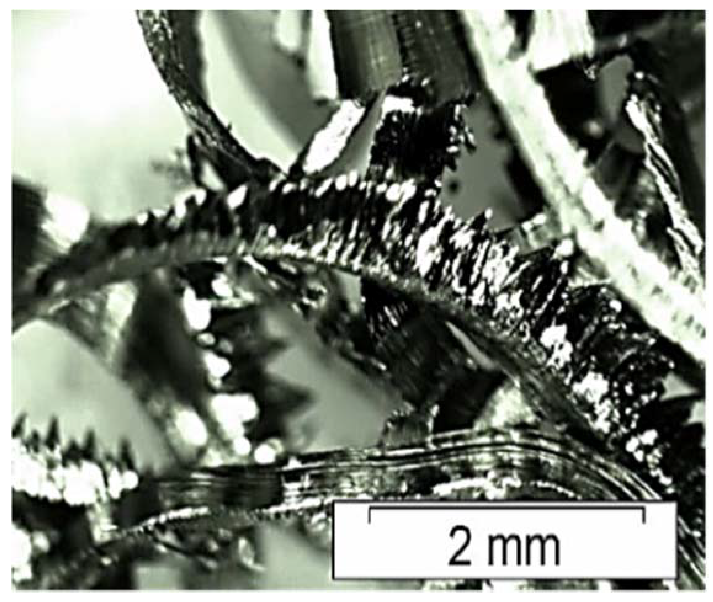
Figure 2.
Micrograph of duplex stainless–steel chips, SEM-secondary electron mode. Increased image of the plastic deformation region.
Figure 2.
Micrograph of duplex stainless–steel chips, SEM-secondary electron mode. Increased image of the plastic deformation region.

Figure 3.
Morphology of the UNS S31803 steel particles with addition of 3% vanadium carbide after high energy milling for 50 h.
Figure 3.
Morphology of the UNS S31803 steel particles with addition of 3% vanadium carbide after high energy milling for 50 h.
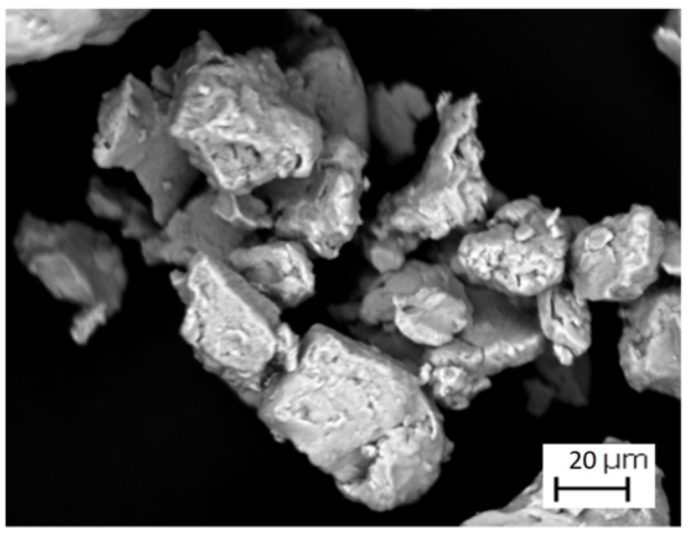
Figure 4.
Parameters D10, D50 and D90 and average particle size after high energy milling for 50 h.

Figure 5.
Micrograph of a stainless–steel sintered at 1250 °C for 1 h. Images obtained by SEM. Secondary electron mode.
Figure 5.
Micrograph of a stainless–steel sintered at 1250 °C for 1 h. Images obtained by SEM. Secondary electron mode.
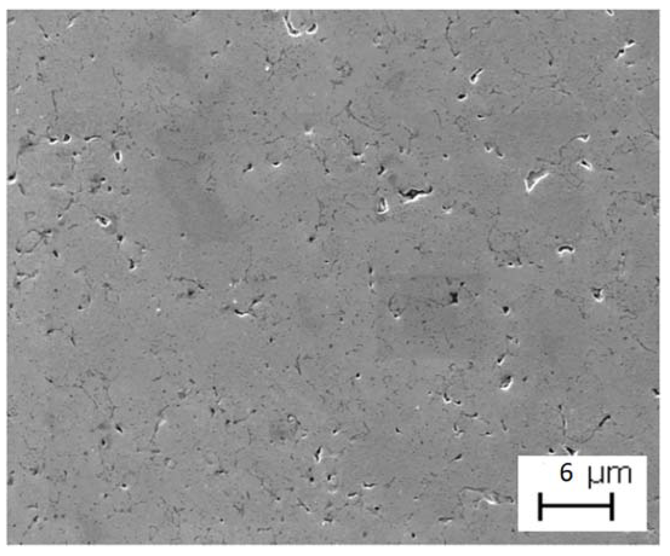
Figure 6.
(a) Distribution of vanadium particles (green) on stainless–steel particles. (b) EDS spectrum of 3% VC added stainless–steel.
Figure 6.
(a) Distribution of vanadium particles (green) on stainless–steel particles. (b) EDS spectrum of 3% VC added stainless–steel.
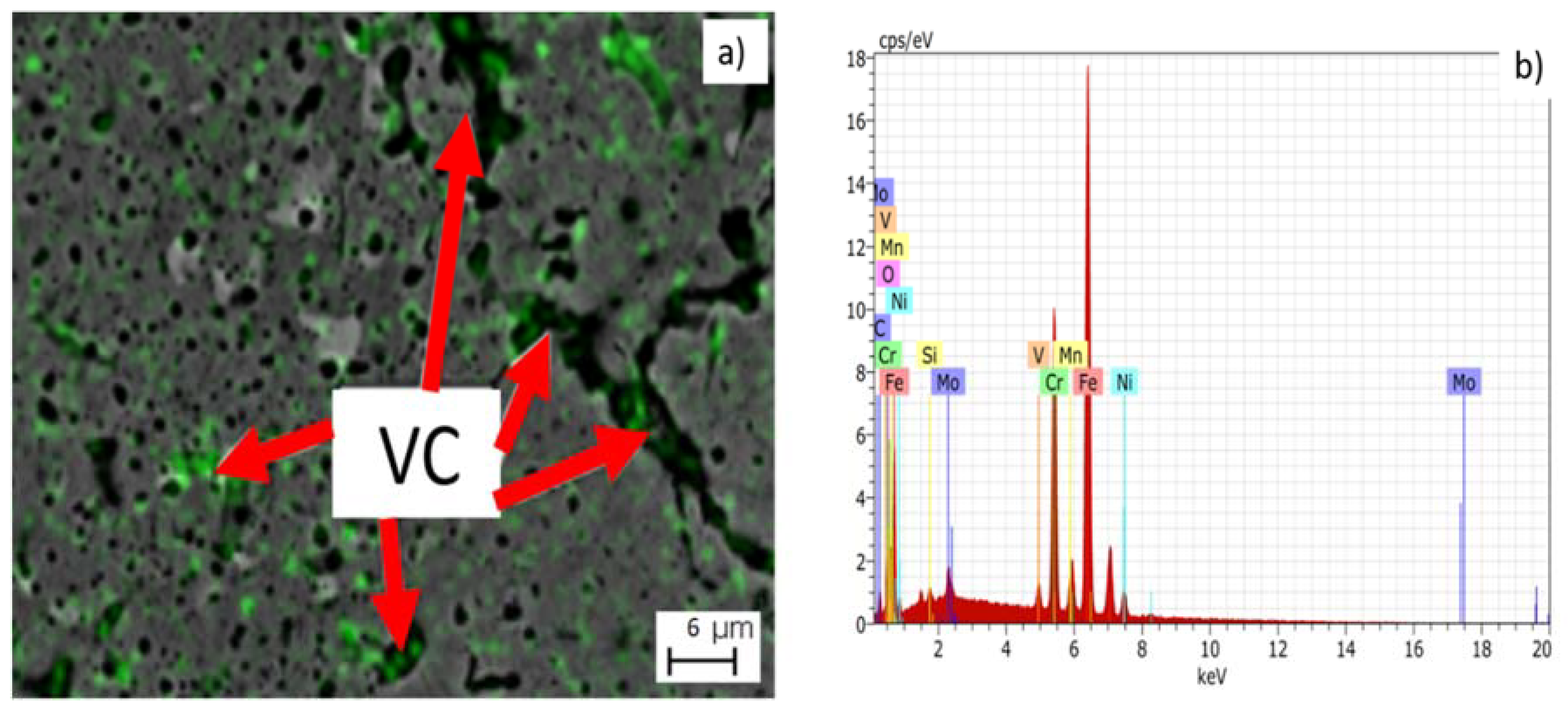
Figure 7.
Sintered stainless–steel microstructure at 1250 °C for 1 h. Regions in red indicate porosity.
Figure 7.
Sintered stainless–steel microstructure at 1250 °C for 1 h. Regions in red indicate porosity.

Figure 8.
Sintered duplex stainless–steel UNS S31803/Vanadium carbide microstructure at 1250 °C for 1 h.
Figure 8.
Sintered duplex stainless–steel UNS S31803/Vanadium carbide microstructure at 1250 °C for 1 h.
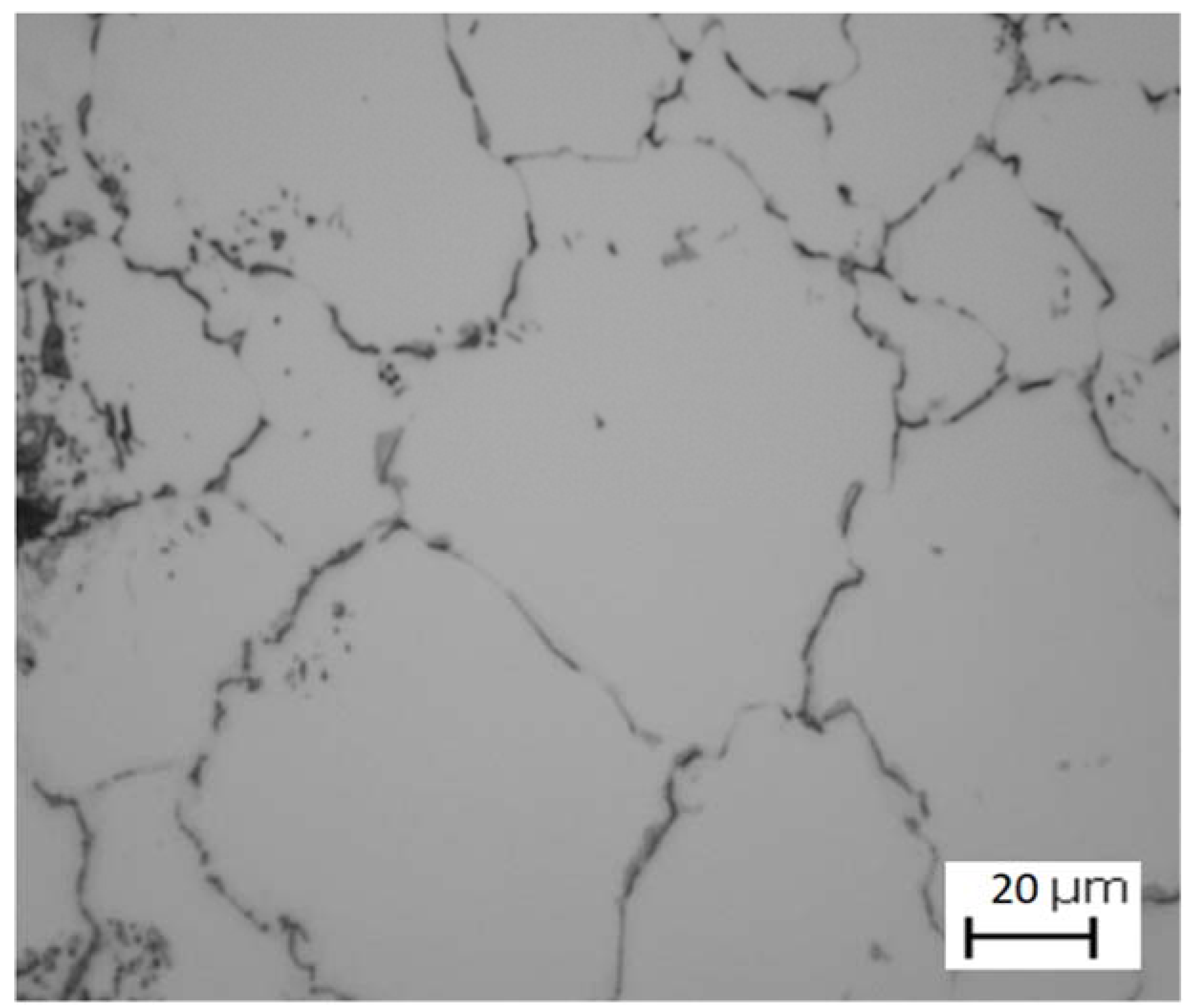
Figure 9.
X-ray diffraction of stainless–steel under the following conditions: (a) as received (b) Milled at the time of 50 h (c) after tension relief treatment of the powder and (d) Sintered at 1250 °C for 1 h.
Figure 9.
X-ray diffraction of stainless–steel under the following conditions: (a) as received (b) Milled at the time of 50 h (c) after tension relief treatment of the powder and (d) Sintered at 1250 °C for 1 h.

Figure 10.
X-ray diffraction spectrum extended between 50° and 54° after milling and also subjected to stress relief and sintering treatment at 1250 °C for 1 h.
Figure 10.
X-ray diffraction spectrum extended between 50° and 54° after milling and also subjected to stress relief and sintering treatment at 1250 °C for 1 h.


Table 1.
Values of green density, sintered material density and Archimedes density of stainless–steel with the addition of 3% VC.
Table 1.
Values of green density, sintered material density and Archimedes density of stainless–steel with the addition of 3% VC.
| Sample | Density in Green (g/cm3) | Density of Arquimedes (g/cm3) |
|---|---|---|
| Duplex stainless–steel/3 wt % VC | 5.08 ± 0.06 | 6.57 ± 0.08 |
Table 2.
Microhardness values of stainless–steel for different conditions.
| Condition | Microhardness (HV) |
|---|---|
| Sample sintering—1250 °C—1 h | 232 ± 8 |
| Material in condition as received | 265 ± 4 |
© 2018 by the authors. Licensee MDPI, Basel, Switzerland. This article is an open access article distributed under the terms and conditions of the Creative Commons Attribution (CC BY) license (http://creativecommons.org/licenses/by/4.0/).
Share and Cite
MDPI and ACS Style
Claudiney, M.; Adhimar, O.; Daniela, S.; Patricia, C.; Vander, R.; Mateus, J.; Mirian, M.; Gilbert, S. A New Method to Recycle Stainless–Steel Duplex UNS S31803 Chips. Metals 2018, 8, 546. https://doi.org/10.3390/met8070546
AMA Style
Claudiney M, Adhimar O, Daniela S, Patricia C, Vander R, Mateus J, Mirian M, Gilbert S. A New Method to Recycle Stainless–Steel Duplex UNS S31803 Chips. Metals. 2018; 8(7):546. https://doi.org/10.3390/met8070546
Chicago/Turabian StyleClaudiney, Mendonça, Oliveira Adhimar, Sachs Daniela, Capellato Patricia, Ribeiro Vander, Junqueira Mateus, Melo Mirian, and Silva Gilbert. 2018. "A New Method to Recycle Stainless–Steel Duplex UNS S31803 Chips" Metals 8, no. 7: 546. https://doi.org/10.3390/met8070546
Note that from the first issue of 2016, this journal uses article numbers instead of page numbers. See further details here.