Influence of Ultrafine Particles on Structure, Mechanical Properties, and Strengthening of Ductile Cast Iron


1
School of Core Engineering Education, National Research Tomsk Polytechnic University, 634050 Tomsk, Russia
2
Department of Mineralogy and Geochemistry, National Research Tomsk State University, 634050 Tomsk, Russia
3
Laboratory of Quality Control of Materials and Constructions, Institute of Strength Physics and Materials Science of Siberian Branch of Russian Academy Society, 634055 Tomsk, Russia
4
Laboratory of Physics, Tomsk State University of Architecture and Building, 634003 Tomsk, Russia
5
Chemical faculty and Laboratory of high-energy and special materials, National Research Tomsk State University, 634050 Tomsk, Russia
*
Author to whom correspondence should be addressed.
Metals 2018, 8(7), 559; https://doi.org/10.3390/met8070559
Submission received: 25 June 2018
/
Revised: 13 July 2018
/
Accepted: 19 July 2018
/
Published: 20 July 2018
Abstract
:Integrated assessment of the influence of an ultrafine mixture TiO2 + ZrO2 + Na3AlF6 on the formation of the structure, mechanical properties, and strengthening of ductile cast iron was made in the paper. The structural-phase composition of ductile cast iron was studied by means of scanning electron microscopy and a transmission electron microscope. Plastic deformation was determined during testing of uniaxial compression. The change in the structural state of the alloy and in its mechanical properties was observed. Quantitative assessment of contributions of separate physical mechanisms to strengthening characteristics of unmodified and modified ductile cast iron was made.
1. Introduction
It is known that the quality and service properties of structural cast irons depend not only on the chemical composition, but in many respects are determined by dispersity and uniformity of the macro- and microstructure of the casting. The obtainment of the alloy in a solid state with a dense (without pores and cracks), fine-grained, and homogeneous structure is an urgent problem of materials science. The most efficient method of improvement of the quality and mechanical properties of structural cast irons is modification by ultrafine and nanopowders of refractory metals [1,2,3,4,5]. When introducing modifiers, based on ultrafine and nanoparticles, into the melt, there is a temperature shift of liquidus and solidus lines in equilibrium state diagrams Fe-C, and a change of the temperature range of crystallisation processes [6], owing to the types of significant changes in the formation of the grain structure and distribution of structural components of Fe-C alloys that take place.
Literature analysis shows that ultra- and nanodispersed particles in small quantities in the capacity of modifiers are effectively used in the alloys of the Fe-C-Cr system [2,5,7,8,9]. Out-of-furnace treatment of the melt of high-chromium irons by adding B4C to the bottom of the casting ladle in the amount of 0.4 mass. % leads to enhancement in homogeneity of the M7C3-type carbide distribution and to hardening of both cast products after thermal treatment [7]. In [2], the results of studies on introduction of 0.2–0.8 mass. % of rare-earth nanoparticles in the melt of high-chromium iron, containing 20 wt. % Cr were presented. It was shown that the greatest effect is achieved when introducing 0.4 mass. %, according to which the homogeneity of distribution of M7C3-type carbides, toughening by ~36%, and a wear resistance increase of ~52% are observed [2].
For modifying grey and high-strength cast irons, inoculators based predominantly on FeSi, with the addition of different rare-earth elements, are used [10,11,12,13,14,15]. Mg, Ce, Y, La, Nd, and Pr, as well as ligatures on their basis, are used as modifiers for obtainment of ductile cast iron [4,15,16,17,18,19,20]. Ni, Cu, Mo, and Si are also by far the most widely used alloying elements in ductile cast irons [21,22]. It is well known that the developed modifiers are used for specific grades of structural cast irons, and as of today, there is no “universal” modifier. The search for new methods of enhancement of strength characteristics of ductile cast irons, including the method of introduction of ultrafine additions and flux cored wires, is an urgent problem [4,13,23,24]. Therefore, the objective of the present research is the determination of the influence of the ultrafine mixture TiO2 + ZrO2 + Na3AlF6 on the crystallisation process, structural-phase state, and mechanical properties of ductile cast iron, revealing the mechanisms of strengthening, and their contribution to the strength characteristics of ductile cast iron.
2. Materials and Methods
The chemical composition of ductile cast iron GRS-600-3U, used in this work, is shown in Table 1.
The modifying mixture (MM) consisted of ultrafine powders TiO2, ZrO2 (with the contents of admixtures Nb, Hf, Mg, Fe, Cr, Sr, and Mo being not more than 5%), and cryolite (Na3AlF6). The particle size in MM was within the range from 0.07 μm to 14 μm, and the average size was ~0.93 μm. The modifying mixture was loaded to the bottom of the casting ladle with an amount of 0.3 mass. %. After soaking of the melt in the furnace, the cast iron was poured into the ladle with the modifier, where the mixture was soaked for 30 min.
The microstructure of alloys, phase localization, and the defect structure were studied by scanning electron microscopy (SEM, an electron microscope Vega II LMU, (TESCAN, s.r.o. Libušina tř. 21 623 00, Brno, Czech Republic) using X-ray energy-dispersive microanalysis INCAEnergy 350 (Oxford, United Kingdom Oxford Instruments Nanoanalysis Halifax Road, High Wycombe, Bucks HP12 3SE, England), and transmission electron microscopy (TEM, JEM-2100F microscope, JEOL Ltd. 1-2, Musashino 3-chome, Akishima, Tokyo, Japan).
The interlamellar distance (Δ) of perlite was determined by SEM images. To measure Δ, the secant method was used. Straight secant lines were drawn perpendicular to cementite wafers so that the straight line crosses 5–10 cementite wafers. The mean value of Δ was calculated by the formula:
where L—length of the straight secant line, N—number of cementite wafers.
Δ = L/N
The dislocation density (ρ) was determined using TEM images by the secant method. To measure ρ, secant lines were used in the form of a rectangular mesh. ρ was calculated according to the formula:
where M—magnification of the photomicrograph; n1 and n2—number of crossings by dislocations of horizontal l1 and vertical l2 lines, respectively (l1 and l2—overall length of horizontal and vertical lines); t—foil thickness.
Plastic deformation was determined during tests for uniaxial compression in a plant Instron ElectroPuls E10000 (Worldwide Headquarters, 825 University Ave, Norwood, MA, USA) at a deformation rate of 0.3 mm/min at room temperature. The hardness measurement was conducted according to the Brinell method under a loading of 30,000 H using a hardness tester TSH-2M (ASMA-Pribor Inc, Svetlovodsk, Ukraine). Three samples were used for each of the tests.
The friction tests were conducted according to a “pin on disc” scheme, realised by the means of a tribometer TRIBOtechnic (TRIBOTECHNIC, 4 rue Valiton, Clichy, France). The sliding velocity was 600 mm/s at a value of normal loading equal to Pn = 12 H. The total distance of the friction path for each sample was 5000 m. The friction was conducted against a ceramic counterbody, made of the VS20 material, without lubrication.
3. Results
3.1. Mechanism of Interaction of Modifying Mixture with Ductile Cast Iron Melt
It is known that the main reason for crystallisation is a reduction of the free energy of the G system when transiting from a liquid to solid state [25]. At that, a minimal in sizes, stable nucleation centre, called critical (rcr), corresponds to an extreme value of the free energy (ΔG). With the radius of the nucleation centre equal to r > rcr, a stable growth of the nucleation centre occurs as ΔG reduces, and with the nucleation centre radius of r < rcr, the nucleation centre being unstable and dissolving in the melt. When modifying the melt of the Fe-C system, assimilated MM becomes a solid dispersed phase. At high temperature, the behaviour of the chemical reactions, along with dissociation of reducing agents and a reduction of active elements from oxides, is possible in the Fe-C system containing MM.
It is necessary to note that an important role in the crystallisation process of the melt belongs to cryolite (Na3AlF6). It is known that a weak intermolecular interaction both among molecules of cryolite itself and when introducing cryolite into the melt is a characteristic feature of nonorganic polyfluorides, to which cryolite belongs [26]. Cryolite is a low-melt constituent of MM, and at temperature of T = 950–1000 °C it decomposes by the formula:
where NaF and NaAlF4 are surfactants. Concurrent reactions of dissociation, breakdown, and reduction-oxidation at high temperatures of the melt are possible.
NaAlF4 → NaF + AlF3 ↑;
2NaF → 2Na + F2, ΔG0298 = −1201 kJ, ΔG01473 = −373 kJ;
2AlF3 →Al + 3F2 ↑, ΔG0298 = −3066 kJ, ΔG01473 = −3359 kJ;
2Na3AlF6 + 3H2O = Al2O3 + 6NaF + 6HF, ΔG0298 = −503 kJ, ΔG01473 = −192 kJ.
Formation of fluoride compounds is thermodynamically possible and experimentally verified. When conducting experimental melting, evolution of gaseous compounds during the introduction of the modifier into the cast iron melt was indicated. Thus, a complex of fluoride salts in the liquid state, gaseous fluorine and hydrofluoric acid, are present in the cast iron melt. Such mixture is a strong reducing agent.
Since iron is a less reactive metal than the metals of MM refractory oxides, the reactions of oxide reduction to metals by iron are impossible. The presence of fluoride compounds facilitates the following reactions:
3TiO2 + 3NaF + 4Al = 3NaAlO2 + AlF3 + 3Ti, ΔG0298 = −330 kJ, ΔG01473 = −319 kJ;
3ZrO2 + 3NaF + 4Al = 3NaAlO2 + AlF3 + 3Zr, ΔG0298 = 112 kJ, ΔG01473 = 137 kJ;
3TiO2 + 6AlF = 3Ti + 2AlF3 + 2Al2O3, ΔG0298 = −1582 kJ, ΔG01473 = 273 kJ;
ZrO2 + 6AlF = 3Zr + 2AlF3 + 2Al2O3, ΔG0298 = −1139 kJ, ΔG01473 = −77 kJ.
Oxides of refractory metals are sufficiently wetted with liquid salts; therefore it is possible to assume the formation of a membrane from the melt of fluoride salts of the powders mixture and secondary disintegration by-products on their surface. The membrane of the particle surface, containing cryolite and fluoride salts, reduces surface tension at the interface “particle-melt”, which enables a facilitated crystallisation process. Local proximity of particles of oxides and reducing agents leads to the reactions of the Ti and Zr reduction from the oxides by aluminium and fluoride salts. Gas generation as a result of cryolite disintegration and interaction with the melt leads to the capture of harmful impurities and their diffusion on the melt surface. Both ultradispersed particles of titanium and zirconium oxides and formed metal fine-dispersed particles of Ti and Zr can lightly diffuse and spread uniformly throughout the whole volume of the cast iron melt, due to gaseous products. As a result of the above-mentioned effects, the concentration of crystallisation centres increases.
Besides, refractory particles of titanium and zirconium oxides with admixtures Nb, Hf, Cr, Sr, Mo (Tmelting = 1521–2758 °C), included in MM, can act as “microrefrigerators” accelerating the cooling rate of the melt and changing the crystallisation conditions. According to the data [25], the introduction of 1% of alloying elements into the melt lowers the melt temperature by approximately 10 °C. In the present paper, when melting cast irons, 0.3% of MM of the melt mass was introduced. With such an amount, the melt temperature can lower by ~1–3 °C. However, the melt temperature is an integral characteristic and the actual melt temperature in this microvolume can be significantly lower than the average temperature of the cast iron melt. As a result of the above-mentioned conditions, the value of melt overcooling, ΔT, and consequently the radius of the critical nucleus, rcr, reduces to r’cr. Thus, nucleation centres from rcr to r’cr, which were earlier unstable and dissolved in the melt, and become stable and are able to grow under new conditions. Consequently, a number of active nucleation centres of crystallisation will increase, and refinement of structural constituents of the melt by the classification of Peter Alexandrovich Rebinder will occur [25].
Thus, when introducing MM into the melt of the Fe-C system, the following occurs: (1) cryolite disintegration, formation of fluoride salts, gaseous products, and metal particles that were reduced from oxides; (2) formation of the multicomponent system “solid body (oxide particles, metal particles)/liquid (melt, fluoride salts)/gas (fluorine, hydrofluoric acid)”; (3) formation of the surface layer by liquid fluoride salts at the interface “solid particle-melt”, enabling a reduction of the surface tension at the interface “solid body-melt”; (4) facilitated particle diffusion throughout the volume of the melt in the presence of gaseous products.
Authors of [27,28] undertook the integrated studies on the influence of the ultrafine mixture TiO2 + ZrO2 + Na3AlF6 on the processes of crystallisation, the structural-phase state, and mechanical properties of high-chromium cast iron Fe–27Cr–2Ni–2.8C and grey cast iron GJL-250. It was established that crystallisation processes of high-chromium cast iron and grey cast iron after the introduction of TiO2 + ZrO2 + Na3AlF6 in the amount of 0.3 mass. % proceeded with a temperature shift of the onset of precipitation of primary and secondary phases by ~20 °C with formation of the structural-phase state typical for the areas of higher temperatures according to the state diagrams of the Fe-C system. The change in the crystallisation process in high-chromium cast iron Fe–27Cr–2Ni–2.8C and grey cast iron GJL-250 leads to a decrease of the sizes of structural constituents of castings (grain structure, carbide-forming phases and flaked graphite), volume fraction and localization of primary phases, as well as parameters of the dislocation structure [29,30]. At this point it is possible to observe an ambiguous influence on mechanical properties of cast iron Fe–27Cr–2Ni–2.8C and grey cast iron GJL-250. It has been established that in high-chromium cast iron Fe–27Cr–2Ni–2.8C after the introduction of TiO2 + ZrO2 + Na3AlF6, strength increases by 53% during compression, and plasticity by 11%. Wear resistance and corrosion resistance of samples increased 1.5–4 times compared to the castings obtained according to a standard factory technology [29]. In grey cast iron GJL-250, after introduction of ultrafine powders, an insignificant increase in the density, strength and wear resistance occurred; at the same time, hardness and plasticity remain unchanged, which is conditioned by dispersion and grain-boundary hardening in samples [30]. The presented data showed that the modifying mixture was effective and can be used for different Fe-C based alloys.
3.2. Influence of Modifying Mixture on Microstructure of Ductile Cast Iron
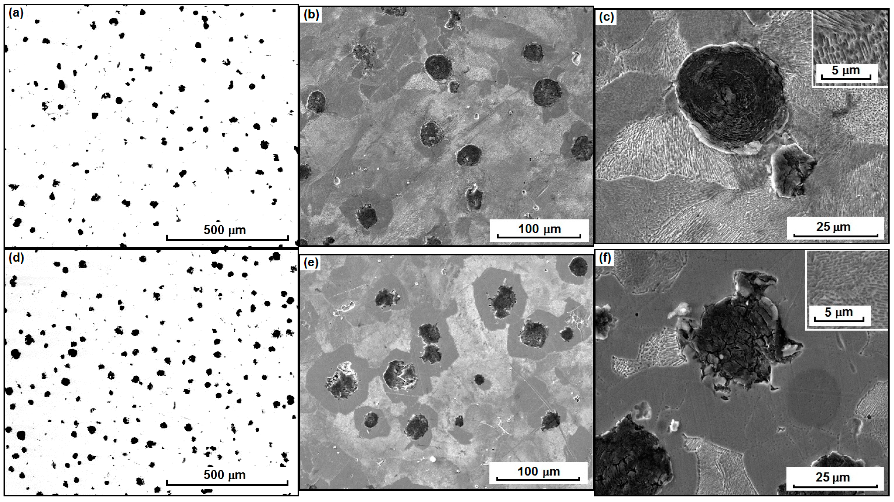
The quality of castings of ductile cast iron was assessed according to the morphology and distribution of graphite rosettes, and the phase composition of the matrix. Figure 1 represents the microstructure of the unmodified and modified alloy.
When conducting metallographic analysis of the surface of metallographic sections GJS-600-3U, it was established that after the introduction of MM, the volume concentration and dispersity of graphite rosettes in samples increased (Figure 1a,d). When assessing the number of graphite rosettes per 1 mm2 of the surface of metallographic sections, it was established that for the unmodified ductile cast iron, the density of localization amounted to 98 pcs/mm2, and for modified ductile cast irons it was 150 pcs/mm2. After the introduction of TiO2 + ZrO2 + Na3AlF6, the number of graphite rosettes increased by 1.5-fold. For the assessment of the graphite rosettes diameter in the unmodified and modified ductile cast irons, statistical processing of data of metallographic sections was conducted and histograms of size distribution of graphite rosettes were plotted in Figure 1a,d and Figure 2. As indicated in Figure 2, the distribution of sizes (diameter) of graphite rosettes in the range between ~5 μm and 45 μm typical for ductile cast irons in both states; the standard deviation salso identical and amounted to 7 μm. It has been established that the average diameter of graphite rosettes in the unmodified ductile cast iron was dav = 21 μm, and in the ductile cast iron after the MM introduction, dav = 17 μm, which was substantially lower compared to the unmodified state.
The introduction of TiO2 + ZrO2 + Na3AlF6 into the melt of ductile cast iron led to refinement of the grain structure of the ferrite-perlite matrix (Figure 1b,e and Figure 3). In unmodified ductile cast irons, the grain size of the ferrite-perlite matrix was in the range of ~8–80 μm, and the average grain size equalled ~38 μm in Figure 3a. After the introduction of MM, the average grain size of the ferrite-perlite matrix reduced by 1.5-fold and amounted to ~25 μm in Figure 3b. The grain size was in the range between 4 and 60 μm. The reduction of the standard deviation and the general view of the histogram of size distribution of grains demonstrated a more concentrated distribution of grains around the average value compared to the unmodified alloy.
According to the SEM data of studies, the matrix of ductile cast iron before and after the MM introduction was characterised by the ferrite-perlite structure in Figure 1c,f. When assessing volume fractions of phases in the melt, it has been established that in the initial samples, the volume fraction of ferrite amounts to ~5–16%, perlite is~86–90%, and graphite is~5–8%. After the introduction of MM into the melt of ductile cast iron, the volume fraction of ferrite increased significantly up to ~20–27%, and its localization changed. In the unmodified ductile cast iron, ferrite grains were randomly located in the matrix in Figure 1c, and in the samples, after the MM introduction, ferrite was localised predominantly around graphite rosettes in the form of interlayers ~10 μm long in Figure 1f. The volume fraction of graphite in the ductile cast iron after the MM introduction increased to ~5–10%; accordingly, and the volume fraction of perlite reduced to ~63–75%. MM introduction led to a more uniform graphite depletion of the austenite matrix and, as a consequence, to the increase of the fraction of ferrite grains during eutectoid transformation. The studies by the SEM method also demonstrated that the dispersion of perlite wafers increased in modified ductile cast iron. For the initial ductile cast iron, perlite dispersion was Δ ≈ 0.52 μm; after the MM introduction, it was Δ ≈ 0.38 μm.
In high-strength cast iron with graphite rosettes, both crystalline and amorphous particles of different chemical compositions could act as the crystallization centres [25]. An increase of the amount and the volume faction of graphite globules, as well as an increase in the volume fraction of ferrite in the samples after introduction of MM, was related to the fact that under the influence of cryolite, superdispersed particles of refractory metal oxides were distributed uniformly throughout the melt volume, being the crystallisation centres and substrates for formation of graphite rosette. Distribution of superdispersed refractory particles in the melt created a multitude of areas with thermal and chemical inhomogeneity, accompanied by the change of crystallisation conditions that do not allow graphite nuclei to stick together and diffuse through the austenite layer. It is known that at average cooling rates, austenite, located near graphite impurities, transforms into ferrite [25]. The residual austenite, located at a distance from graphite, decomposes during eutectic reaction accompanied by perlite formation [25]. According to literature data, the ferritisation process is characteristic for low cooling rates of castings [25], which is experimentally confirmed by the curve of cooling of high-strength cast iron after introduction of MM, for which an increase in the temperature interval of precipitation of primary phases by ~50 °C is observed, thus decreasing the cooling rate of castings and, consequently, increasing the volume fraction of ferrite.
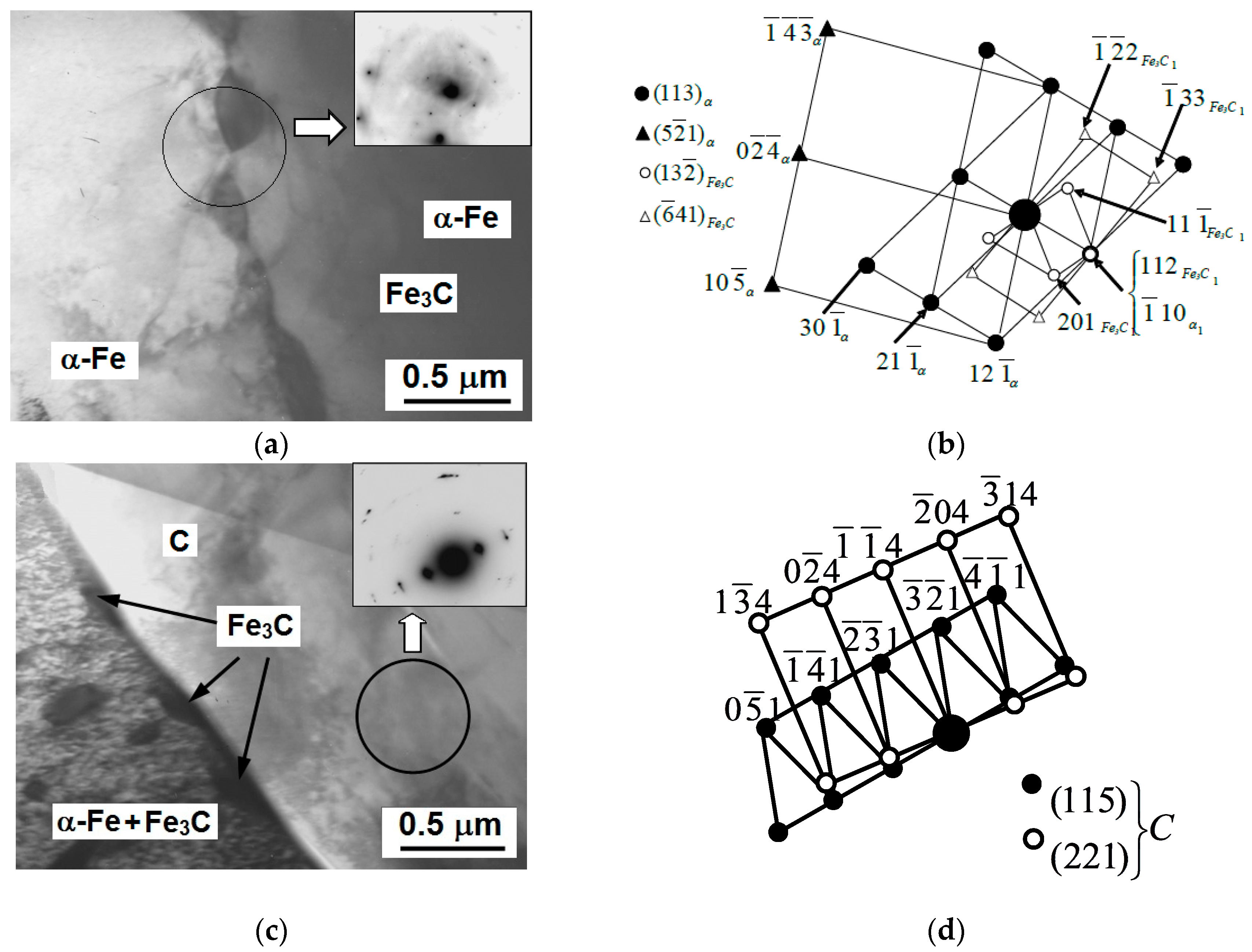
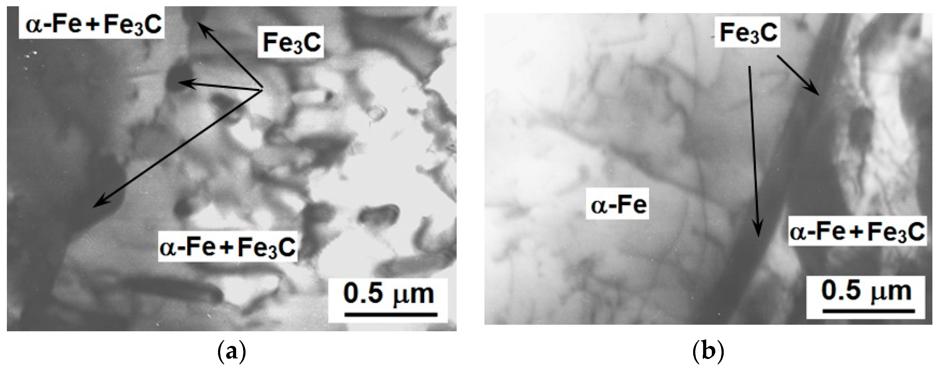
SEM data are confirmed by TEM data, according to which it is established that unmodified and modified ductile cast iron consists of the ferrite-perlite matrix and graphite rosettes. According to TEM data, in ductile cast irons before and after the MM introduction, the ferrite-perlite structure is of defective nature in Figure 2 and Figure 3. The dislocation density in the perlite structure of the unmodified ductile cast iron amounts to ~1.19 × 1010 cm−2, in ferrite—~1.0 × 1010 cm−2 (Figure 4). After the MM introduction into the melt of ductile cast iron, the dislocation density, which equals ~0.61 × 1010 cm−2 for perlite and ~0.47 × 1010 cm−2 for ferrite, reduces (Figure 5).
It is worth noting that according to SEM and TEM data, MM particles in the structure of ductile cast iron were not detected. According to the mechanism, presented in Section 3.1, it is determined by particles dissolution in the melt owing to chemical reactions and, probably, partial particle precipitation on the periphery of the casting.
3.3. Influence of Modifying Mixture on Mechanical Properties and Strengthening of Ductile Cast Iron
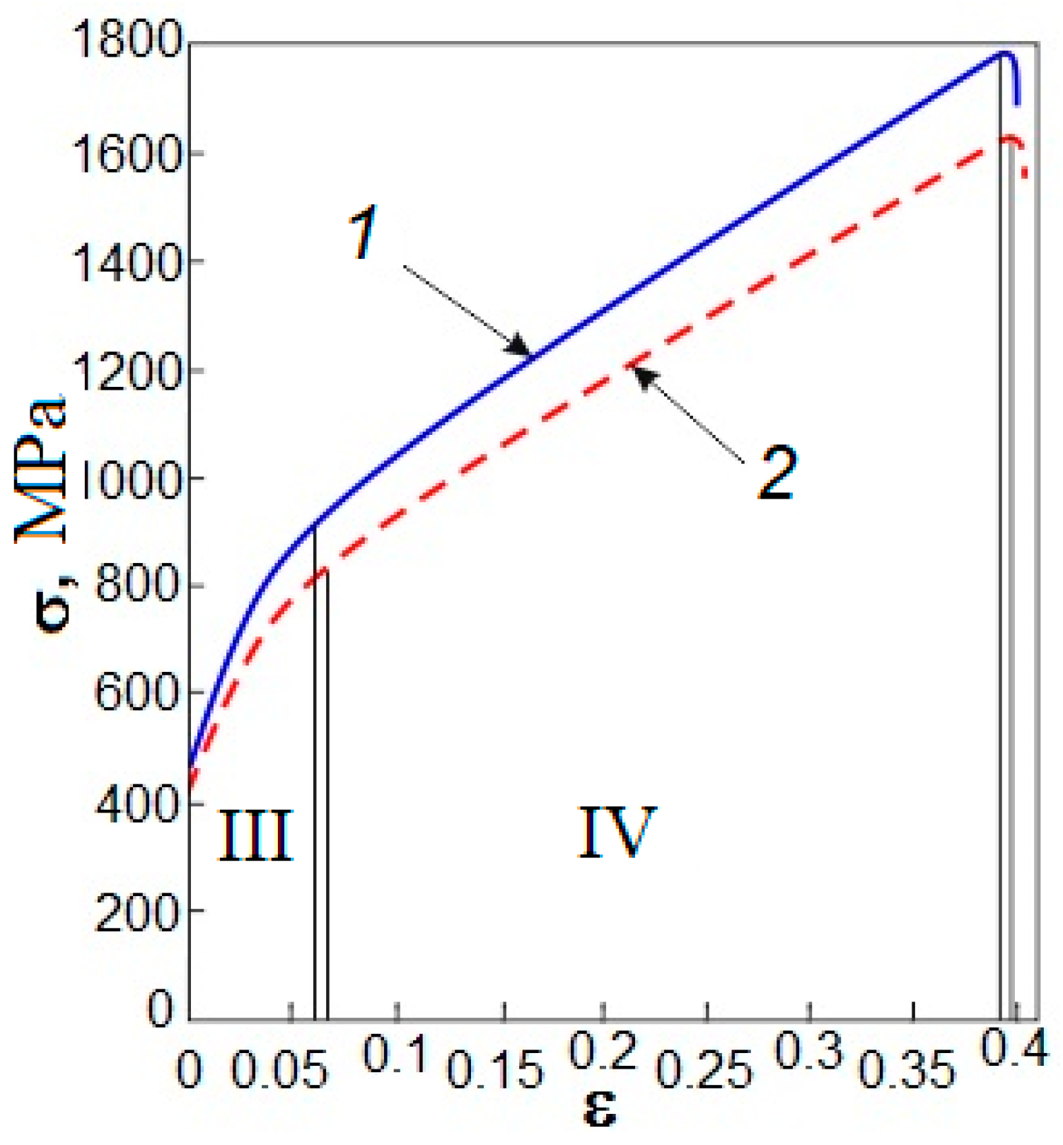
As a result of modification of ductile cast iron, yield strength σ0.2 was reduced by 40 MPa. Tensile strength σB reduced during compression from 1780 MPa to 1620 MPa. At the same time, elongation δ was virtually retained (Figure 6, Table 2). The durations of stage III ΔεIII and stage IV ΔεIV remain unchanged. The strain-hardening coefficient at stage IV ΔσIV reduced slightly after the MM introduction. Hardness and density of ductile cast iron after the MM introduction did not change and were 286 HB ± 5% and 7200 ± 100 kg/m3, correspondingly.
A lower value of yield stress of the modified alloy was observed, especially, at stage IV. This was determined by the change of the ratio between perlite and ferrite. After the MM introduction, an increase in the volume fraction of ferrite and the number of graphite rosettes, and a decrease in the volume fraction of perlite and the size of its carbide precipitation were observed. The determining influence on the enhancement of strength properties was exerted by the perlite matrix, the amount of which decreases, which led to a decrease of the yield stress in the alloy with the modifier.
Wear tests are performed according to the scheme “pin on disc”. The value of the friction coefficient demonstrated low deviation from the average value, which was practically constant for the whole friction path for both unmodified and modified ductile cast irons. The data stability allowed for the indicated phenomenon being connected with the properties of samples’ material, but not for instrumental error and other random factors. The studies on wear resistance showed that the average friction coefficient for initial samples of ductile cast iron was 0.51 and for the samples after the MM introduction 0.49. Linear wear of samples of ductile cast iron as a result of the MM introduction also decreased from 0.36 mm to 0.25 mm. This was a better index for the products made of ductile cast iron, operating in a wear-and-tear mode (discs, brakes, shoes, etc.).
3.4. Contribution of Physical Mechanisms to Yield Stress
Strengthening of metal alloys depends on the number of factors, their role in each particular case will be different, and the share of contribution of separate strengthening mechanisms to the overall strengthening of the material is also unequal [31,32,33]. The studies show that after the introduction of TiO2 + ZrO2 + Na3AlF6 into the melt of ductile cast iron, the following processes take place: (1) volume fractions of ferrite and perlite change, and ferrite grains settle in around graphitic precipitations; (2) the dispersity of the ferrite-cementite structure of perlite grains increases; (3) the number of graphite rosettes increases by 1.5-fold; (4) the grain size of the ferrite-perlite matrix decreases, etc. Such changes in the structure of ductile cast irons after the MM introduction lead to the reduction of the yield stress by 40 MPa, tensile strength by 140 MPa, and the increase of wear resistance by 18%. For the assessment of the contribution of structural constituents to the yield strength (Δσy) of ductile cast iron, it is expedient to use the ratio [31,32]:
where ΔσF—yield strength of ferrite; Δσperlite—yield strength of perlite; PF and Pp—volume fractions of ferrite and perlite, accordingly; Δσg—grain boundary strengthening.
According to [30,31,32], the yield strength of ferrite presupposes the linear summation:
where σ0—stress of dislocations friction in a lattice; Δσsol.s—strengthening of the solid solution by the alloying elements and admixtures dissolved in it; Δσd—strengthening conditioned by resistance of sliding dislocation to other dislocations in a crystal (deformation strengthening).
According to [32,33], for alloys, based on perlite, contributions to the strengthening mechanisms are somewhat different compared to those in the alloys based on the ferritic matrix. That is, in perlite alloys, Orovan mechanisms do not act, but barrier braking does in perlite colonies. Therefore, the contribution to the yield strength of perlite alloys is determined as a contribution to the yield strength of perlite by the following ratio:
where ΔσP—perlite strengthening determined as [30]:
where t—the distance between cementite wafers in the colonies of lamellar perlite; β = 1/6—const; —the average value of shear modulus of ferrite and cementite ( MPa); bc = 0.225 nm—Burgers vector of cementite.
Friction stress of lattice, σ0: Resistance of a lattice to the movement of free dislocations or Peierls-Nabarro stress in the first approximation can be brought into correlation with the yield strength of a metal monocrystal, since this value is minimal stress for the motion of edge dislocations in the crystal and characterises friction forces in it. According to data [32,34], the friction stress for all monocrystals after accepting a number of approximations is determined as:
According to the data of reference materials [32], the mechanical properties of pure metals and values of Peierls-Nabarro stress for alloys, based on α-Fe, are σ0 ≈ 30 MPa.
Solid-solution strengthening, Δσsol.s: The assessment of the contribution of solid solution strengthening to the yield strength of ductile cast iron is determined according to the ratio [31,32]:
where ki—the strengthening coefficient of ferrite when dissolving 1 mass. % of the i-th alloying element; Ci—concentration of the i-th alloying element dissolved in ferrite. The values of the strengthening coefficients of the main alloying elements are taken from source [35].
Such elements as Mn, Si, Ni, and P are in practice entirely included into the matrix composition, and the content of such elements as C, Cr, V, Ti, and others depends on the quantity of strengthening carbide-forming phases [32]. Since carbide-forming phases do not form in ductile cast irons, except for cementite, let us suppose that the presence of alloying elements in ferrite and perlite will be similar, and according to ratio (8), it will amount to Δσsol.s = 192 MPa for unmodified ductile cast iron and Δσsol.s = 176 MPa—for modified ductile cast iron. In spite of the fact that the chemical composition of ductile cast irons before and after the MM introduction is virtually identical, a decrease of Δσsol.s in the modified ductile cast iron was conditioned by a slight decrease in the content of Si (by 0.2 mass. %).
Deformation strengthening, Δσd: According to [33], it is possible to assess the given contribution to the dislocation structure, not containing explicit balls and cells, according to the following ratio:
where α—dimensionless coefficient which changes within the range of 0.05–1, depending on the type of a dislocation ensemble; m—orientational multiplier (for α-Fe—m = 2.75, and α—m = 0.5); G—shear modulus; b—Burgers vector; ρ—dislocations density.
It is obvious that the reduction of scalar density of dislocations in the ferrite-perlite matrix of the modified ductile cast iron led to the decrease of the contribution from substructural strengthening to the yield strength (Table 3).
Grain-boundary strengthening, Δσg: The introduction of TiO2 + ZrO2 + Na3AlF6 into the melt of ductile cast irons led to a 1.5-fold refinement of the grain structure of the ferrite-perlite matrix. The contribution to the grain-boundary strengthening is calculated according to Hall-Petch relationship [31,32]. Taking into consideration the average grain size of the matrix, the contribution to the grain-boundary strengthening for the unmodified cast iron was 107 MPa and for modified cast iron it was Δσg = 120 MPa.
Perlite strengthening, ΔσP: The contribution to perlite strengthening, according to (6), also demonstrated a greater value for modified ductile cast irons than that for unmodified ductile cast irons. For the unmodified ductile cast irons, ΔσP = 120 MPa, and for the modified, ΔσP = 140 MPa. This was connected with the fact that after the MM introduction to the melt of ductile cast iron, the dispersity of the ferrite-cementite structure of perlite grains increased.
Thus, the yield strength of ferrite (ΔσF) for the unmodified ductile cast iron, taking into consideration the volume fraction, was 19 MPa, and for the modified ductile cast iron, ΔσF = 59 MPa (Table 4). Considering the changes of volume fractions of the ferrite-perlite structure in modified ductile cast irons, according to ratio (3), the yield strength of perlite, Δσperlite, of unmodified ductile cast irons was 349 MPa, and of modified was 261 MPa. When assessing the strengthening, the graphite contribution was not taken into consideration due to insignificant differences of the parameters of its distribution.
The obtained values of contributions of different strengthening mechanisms correlated well with experimental data. It has been established that the MM introduction into the melt of ductile cast iron leads to lesser strengthening as a result of: (1) solid-solution strengthening (owing to the reduction of elements content); (2) substructural strengthening owing to a two-time reduction of dislocations density; (3) perlite strengthening owing to the reduction of the volume fraction of perlite by 19%.
4. Conclusions
The mechanisms of processes, proceeding as a result of MM introduction based on superdispersed particles TiO2, ZrO2, and cryolite into the cast iron melt, are proposed: (1) decomposition of cryolite, formation of fluoride salts, gaseous products and metallic particles reduced from oxides; (2) formation of the multicomponent system of solid body (oxide particles, metal particles)/liquid (melt, fluoride salts)/gas (fluorine, hydrofluoric acid); (3) formation of the surface layer at an interface “solid particle-melt” from liquid fluoride salts enabling a surface tension reduction in the Fe-C system; (4) facilitated particle diffusion throughout the melt volume in the presence of gaseous products.
The influence of MM based on ultrafine particles of TiO2, ZrO2, and cryolite at an amount of 0.3 mass. % on the microstructure and mechanical properties of ductile cast iron, when retaining base phase composition (α-Fe, Fe3C and C), has been studied. Based on the foregoing, it is possible to draw the following conclusions:
- It has been demonstrated that the change of crystallisation conditions of ductile cast iron after MM introduction results in: (1) an increase of the volume fraction of ferrite by 19% and graphite rosettes by 2%; (2) a 1.5-fold reduction of the average grain size of the ferrite-perlite matrix; (3) an increase in dispersity of the ferrite-cementite structure of perlite grains; (4) a 1.5-fold increase of a number of graphite rosettes.
- It has been established that the changes in the structure of ductile cast irons after the MM introduction have led to a decrease of tensile strength by 160 MPa and to an increase of wear resistance by ~10%; at the same time, density, plasticity, and hardness of samples of ductile cast irons remain unchanged.
- A quantitative assessment of contributions of mechanisms of ductile cast iron strengthening has been made. The reduction of the yield point of ductile cast iron after the MM introduction occurs owing to the reduction of the following contributions: (1) solid-solution strengthening owing to the lowering of the Si content by 0.2 mass. %; (2) substructural strengthening owing to a two-time reduction of dislocations density; (3) perlite strengthening owing to a decrease of the volume fraction of perlite by 19%. In all probability, the retention of the plasticity of the modified alloy is connected with interference of two opposite mechanisms: a plasticity increase owing to the increase of ferrite areas around graphite impurities, and a plasticity reduction owing to a 1.5-fold increase in a number of graphite rosettes being potential spots of initiation and propagation of cracks.
Thus, it is possible to note that MM TiO2 + ZrO2 + Na3AlF6, after its introduction into Fe-C cast irons, unambiguously leads to significant refinement of structural constituents, but ambiguously influences the mechanical properties. In high-chromium cast iron Fe–27Cr–2Ni–2.8C and grey cast iron GJL-250, there is an enhancement of mechanical properties, but in ductile cast iron GJS-600-3U there is a strength reduction related to a decrease in the perlite volume fraction, and an increase of the ferrite volume fraction.
Author Contributions
A.Z. wrote the paper; A.C. conducted research on mechanical properties; N.P. conducted research on transmission electron microscopy and scanning electron microscopy; D.L. and I.K. managed the experimental work and made correction in the article.
Funding
This research (project No 8.2.02.2018) was carried out with the support of the Program of increasing the competitiveness of TSU and the Russian Foundation for Basic Research, according to the research project No 13-02-98034 r_sibir_a.
Conflicts of Interest
The authors declare no conflict of interest.
References
- Kalinin, V.T.; Hrychikov, V.E.; Krivosheev, V.A.; Menyailo, E.V. Theory and practice of modifying iron ultra- and nanodispersed materials. Metall. Min. Ind. 2010, 2, 341–347. [Google Scholar]
- Hou, Y.; Wang, Y.; Pan, Z.; Yu, L. Influence of rare earth nanoparticles and inoculants on performance and microstructure of high chromium cast iron. J. Rare Earths 2012, 30, 283–288. [Google Scholar] [CrossRef]
- Saburov, V.P. Suspension modifying of steels and alloys with ultradispersed powders. Liteinoe Proizv. 1991, 4, 14–19. [Google Scholar]
- Ferro, P.; Fabrizi, A.; Cervo, R.; Carollo, C. Effect of inoculant containing rare earth metals and bismuth on microstructure and mechanical properties of heavy-section near-eutectic ductile iron castings. J. Mater. Process. Technol. 2013, 213, 1601–1608. [Google Scholar] [CrossRef]
- Chung, R.J.; Tang, X.; Li, D.Y.; Hinckley, B.; Dolman, K. Effects of titanium addition on microstructure and wear resistance of hypereutectic high chromium cast iron Fe–25wt.%Cr–4wt.%C. Wear 2009, 267, 356–361. [Google Scholar] [CrossRef]
- Opsen, S.O.; Scaland, T.; Hartung, K. Modification of grey and high-strength cast irons. Comparison of crystallisation centres of graphite and some practical recommendations on modification. Liteyshchik Rossii 2011, 2, 29–34. [Google Scholar]
- Kopycinski, D. Inoculation of chromium white cast iron. Arch. Foundry Eng. 2009, 9, 191–194. [Google Scholar]
- Venkatraman, M.; Neumann, J.P. The Cr-C System. Bull. Alloy Ph. Diagr. 1990, 11, 152–164. [Google Scholar] [CrossRef]
- Zhi, X.H.; Xing, J.D.; Fu, H.G.; Xiao, B. Effect of niobium on the as-cast microstructure of hypereutectic high chromium cast iron. Mater. Lett. 2008, 62, 857–860. [Google Scholar] [CrossRef]
- Collini, L.; Nicoletto, G.; Konecna, R. Microstructure and mechanical properties of pearlitic gray cast iron. Mater. Sci. Eng. A 2008, 488, 529–539. [Google Scholar] [CrossRef]
- Borse, S.C.; Mangulkar, Y.E. Review on grey cast iron inoculation. Int. J. Innov. Res. Sci. 2004, 3, 30–36. [Google Scholar]
- Olsen, S.O.; Skaland, T.; Hartung, C. Inoculation of grey and ductile iron a comparison of nucleation sites and some practical advises. In Proceedings of the 66th World Foundry Congress, Istanbul, Turkey, 6–9 September 2004; Volume 1, p. 12. [Google Scholar]
- Cho, G.S.; Choe, K.H.; Lee, K.W.; Ikenaga, A. Effects of alloying elements on the microstructures and mechanical properties of heavy section ductile cast iron. J. Mater. Sci. Technol. 2007, 23, 97–101. [Google Scholar]
- Alasoluyi, J.O.; Omotoyinbo, J.A.; Olusunle, S.O.O.; Adewoye, O.O. Investigation of the mechanical properties of ductile iron produced from hybrid inoculants using rotary furnace. Int. J. Sci. Technol. 2013, 2, 388–393. [Google Scholar]
- Yamane, K.; Yasuda, H.; Sugiyama, A.; Nagira, T.; Yoshiya, M.; Morishita, K.; Uesugi, K.; Takeuchi, A.; Suzuki, Y. Influence of Mg on solidification of hypereutectic cast iron: X-ray radiography study. Metall. Mater. Trans. A 2015, 46, 4937–4946. [Google Scholar] [CrossRef]
- Dasgupta, R.K.; Mondal, D.K.; Chakrabarti, A.K. Evolution of microstructures during austempering of ductile irons alloyed with manganese and copper. Metall. Mater. Trans. A 2013, 44, 1376–1387. [Google Scholar] [CrossRef]
- Kovalevich, E.V. Methods of cast iron inoculation to produce globular shape of graphite. Liteynoye Proizv. 2006, 4, 2–5. [Google Scholar]
- Anikin, A.A.; Venig, S.B.; Bilenko, D.I.; Gribov, A.N.; Zhukov, A.G. Globular graphite: Structure, composition. Met. Sci. Heat Treat. 2014, 56, 113–117. [Google Scholar] [CrossRef]
- Larrañaga, P.; Asenjo, I.; Sertucha, J.; Suarez, R.; Ferrer, I.; Lacaze, J. Effect of antimony and cerium on the formation of chunky graphite during Solidification of heavy-section castings of near-eutectic spheroidal graphite irons. Metall. Mater. Trans. A 2009, 40, 654–661. [Google Scholar] [CrossRef] [Green Version]
- Bedolla-Jacuinde, A.; Solis, E.; Hernandez, B. Effect of niobium in medium alloyed ductile cast irons. Int. J. Cast Met. Res. 2003, 16, 3–9. [Google Scholar] [CrossRef]
- Konca, E.; Tur, K.; Koc, E. Effects of alloying elements (Mo, Ni, and Cu) on the austemperability of GGG-60 ductile cast iron. Metals 2017, 7, 320. [Google Scholar] [CrossRef]
- Song, L.; Guo, E.; Wang, L.; Liu, D. Effects of silicon on mechanical properties and fracture toughness of heavy-section ductile cast iron. Metals 2015, 5, 150–161. [Google Scholar] [CrossRef]
- Sluzov, A.; Sedunov, V.; Korovin, V.; Leushin, I. Improvement of the process of modifying high-strength cast iron. Liteyshchik Rossii 2015, 7, 9–12. [Google Scholar]
- Shen, X.P.; Harris, S.J.; Noble, B. Influence of small vanadium and cobalt additions on microstructure and properties of ductile iron. J. Mater. Sci. Technol. 1995, 11, 893–900. [Google Scholar] [CrossRef]
- Minkoff, I. The Physical Metallurgy of Cast Iron; John Wiley Sons Ltd.: Hoboken, NJ, USA, 1983; p. 318. [Google Scholar]
- Petrov, V.A. Fluorinated Heterocyclic Compounds: Synthesis, Chemistry, and Applications; John Wiley & Sons Ltd.: Hoboken, NJ, USA, 2009; p. 533. [Google Scholar]
- Zykova, A.P.; Kurzina, I.A.; Lychagin, D.V.; Chumaevsky, A.V.; Kachaev, A.A.; Bataev, V.A. Structural state, phase composition and mechanical properties of wear-resistant cast iron modified by ultrafine powders. Adv. Mater. Res. 2014, 872, 84–88. [Google Scholar]
- Zykova, A.P.; Lychagin, D.V.; Chumaevsky, A.V.; Kurzina, I.A.; Novomeysky, M.Y. Influence of modifying of cast iron SCH25 (russian grade) with ultrafine powders of refractory metal oxide and cryolite on structure, mechanical properties and fracture. Izvestiya Vysshikh Uchebnykh Zavedenij. Chernaya Metallurgiya 2014, 57, 37–42. [Google Scholar] [CrossRef]
- Zykova, A.P.; Popova, N.A.; Kurzina, I.A. Influence of ultradispersed powders TiO2, ZrO2 and cryolithe for the strengthening of SCH25. Russ. J. Bas. Probl. Mater. Sci. 2016, 13, 204–209. [Google Scholar]
- Zykova, A.P.; Popova, N.A.; Nikonenko, E.L.; Kurzina, I.A. Effect of ultradisperse TiO2, ZrO2, and cryolite powders on high-chromium cast iron hardening. Bull. Russ. Acad. Sci. Phys. 2017, 80, 1317–1321. [Google Scholar] [CrossRef]
- Bhadeshia, H.K.D.H.; Honeycombe, R.W.K. Steels: Microstructure and Properties. Textbook, 3rd ed.; Butterworth-Heinemann: Oxford, UK, 2006; p. 360. [Google Scholar]
- Goldstein, M.I.; Farber, V.M. Dispersion Steel Strengthening; Metallurgy: Moscow, Russia, 1979; p. 208. [Google Scholar]
- Koneva, N.A.; Kozlov, E.V. Regularities of substructural strengthening. Sov. Phys. J. 1991, 34, 224–236. [Google Scholar] [CrossRef]
- Tushinskii, L.I.; Bataev, A.A. Substructural strengthening of steel. Sov. Phys. J. 1991, 34, 237–243. [Google Scholar] [CrossRef]
- Lin, D.M. Mechanical Properties of Metals; Metallurgy: Moscow, Russia, 1965; p. 618. [Google Scholar]
Figure 1.
Microstructure of ductile cast iron GJS-600-3U: unmodified (a–c); modified (d–f); as-polished microstructures (a,d); and etched microstructures (b,c,e,f).
Figure 1.
Microstructure of ductile cast iron GJS-600-3U: unmodified (a–c); modified (d–f); as-polished microstructures (a,d); and etched microstructures (b,c,e,f).

Figure 2.
Histogram of size distribution of graphite rosettes in unmodified (a) and modified (b) ductile cast irons.
Figure 2.
Histogram of size distribution of graphite rosettes in unmodified (a) and modified (b) ductile cast irons.
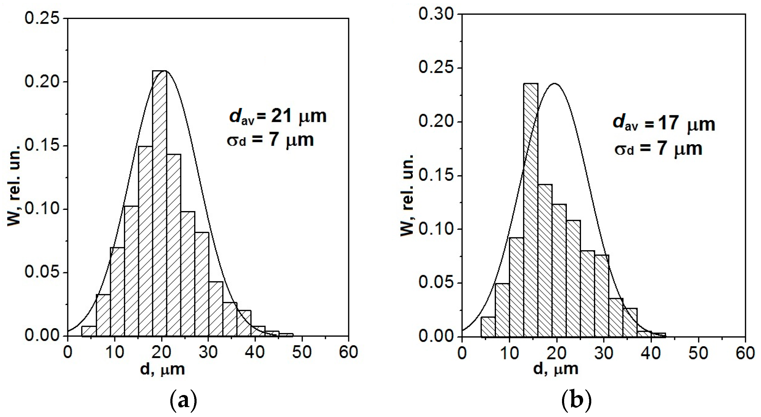
Figure 3.
Histogram of size distribution of grains of ferrite-perlite matrix in unmodified (a) and modified (b) ductile cast irons.
Figure 3.
Histogram of size distribution of grains of ferrite-perlite matrix in unmodified (a) and modified (b) ductile cast irons.
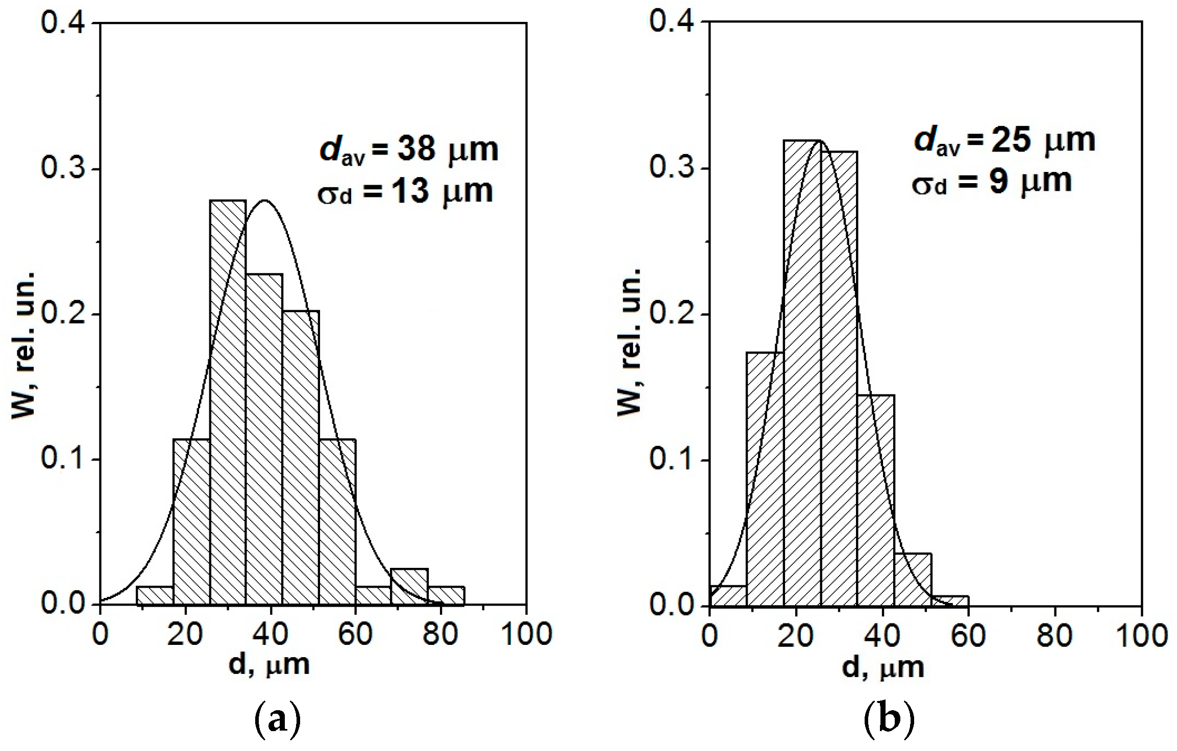
Figure 4.
Electron microscope image of dislocation structure of unmodified ductile cast iron, micro-diffraction pattern, taken of precipitated areas: (a) boundary “ferrite-ferrite” and its indicated scheme (b); (c) boundary “perlite-graphite” and its indicated scheme (d).
Figure 4.
Electron microscope image of dislocation structure of unmodified ductile cast iron, micro-diffraction pattern, taken of precipitated areas: (a) boundary “ferrite-ferrite” and its indicated scheme (b); (c) boundary “perlite-graphite” and its indicated scheme (d).

Figure 5.
Dislocation structure in modified ductile cast iron: (a) boundary “perlite-perlite”; (b) boundary “ferrite-perlite”.
Figure 5.
Dislocation structure in modified ductile cast iron: (a) boundary “perlite-perlite”; (b) boundary “ferrite-perlite”.

Figure 6.
Dependence of stress on deformation of unmodified (1) and modified (2) ductile cast irons.
Figure 6.
Dependence of stress on deformation of unmodified (1) and modified (2) ductile cast irons.


Table 1.
Chemical Composition (mass. %) of ductile iron alloy.
| Ductile Cast Iron | C | Si | Mn | Ni | Mo | Cr | P | Ca | Al | S | Fe |
|---|---|---|---|---|---|---|---|---|---|---|---|
| Unmodified | 3.4 | 1.8 | 0.1 | 0.7 | 0.2 | 0.03 | 0.01 | 0.4 | 0.02 | 0.01 | Bal. |
| Modified | 3.4 | 1.6 | 0.1 | 0.8 | 0.2 | 0.03 | 0.01 | 0.4 | 0.02 | 0.01 | Bal. |
Table 2.
Characteristics of deformation curves of unmodified and modified ductile cast irons.
| Ductile Cast Iron | σ0,2, MPa | σB, MPa | δ, % | ΔεIII, % | ΔεIV, % | σIV, MPa | ΘIV, MPa |
|---|---|---|---|---|---|---|---|
| Unmodified | 450 | 1780 | 39.0 | 6.0 | 33 | 1030 | 2300 |
| Modified | 410 | 1620 | 39.5 | 6.5 | 33 | 880 | 2200 |
Table 3.
Values of parameters of deformation strengthening in ductile cast irons.
| Ductile Cast Iron | Scalar Density of Dislocations, ρ × 10−10 cm−2 | Δσd, MPa | Scalar Density of Dislocations on Average throughout Matrix, ρ × 10−10 cm−2 | Δσd on Average throughout Matrix, MPa | ||
|---|---|---|---|---|---|---|
| F | P | F | P | |||
| Unmodified | 1.0 | 1.2 | 55 | 64 | 1.1 | 60 |
| Modified | 0.5 | 0.6 | 38 | 43 | 0.55 | 41 |
Table 4.
Yield strength, tensile strength, and contributions of separate mechanisms to strengthening of ductile cast irons.
Table 4.
Yield strength, tensile strength, and contributions of separate mechanisms to strengthening of ductile cast irons.
| Ductile Cast Iron | σ0,2, MPa | σB, MPa | Δσ0, MPa | Δσsol.s, MPa | Δσd, MPa | ΔσP, MPa | Δσg, MPa | Δσy Considering PF and PP, MPa | Δσy, MPa | ||
|---|---|---|---|---|---|---|---|---|---|---|---|
| F | P | F | P | ||||||||
| Unmodified | 450 | 1780 | 30 | 192 | 55 | 64 | 120 | 107 | 19 | 349 | 475 |
| Modified | 410 | 1620 | 30 | 176 | 38 | 43 | 140 | 120 | 59 | 261 | 440 |
© 2018 by the authors. Licensee MDPI, Basel, Switzerland. This article is an open access article distributed under the terms and conditions of the Creative Commons Attribution (CC BY) license (http://creativecommons.org/licenses/by/4.0/).
Share and Cite
MDPI and ACS Style
Zykova, A.; Lychagin, D.; Chumaevsky, A.; Popova, N.; Kurzina, I. Influence of Ultrafine Particles on Structure, Mechanical Properties, and Strengthening of Ductile Cast Iron. Metals 2018, 8, 559. https://doi.org/10.3390/met8070559
AMA Style
Zykova A, Lychagin D, Chumaevsky A, Popova N, Kurzina I. Influence of Ultrafine Particles on Structure, Mechanical Properties, and Strengthening of Ductile Cast Iron. Metals. 2018; 8(7):559. https://doi.org/10.3390/met8070559
Chicago/Turabian StyleZykova, Anna, Dmitry Lychagin, Andrey Chumaevsky, Natalya Popova, and Irina Kurzina. 2018. "Influence of Ultrafine Particles on Structure, Mechanical Properties, and Strengthening of Ductile Cast Iron" Metals 8, no. 7: 559. https://doi.org/10.3390/met8070559
Note that from the first issue of 2016, this journal uses article numbers instead of page numbers. See further details here.