Retained Austenite Control for the Soft Machining of High-Hardness Tool Steels


1
Metallurgy Research Centre IK4 AZTERLAN, Metallurgical Processes, Forming Technology Unit, Aliendalde Auzunea 6, 48200 Durango, Spain
2
IK4-Tekniker, Advanced Manufacturing Technologies Unit, Polo Tecnológico de Eibar, Iñaki Goenaga 5, 20600 Eibar, Spain
3
Department of Mechanical Engineering, University of the Basque Country (UPV/EHU), Plaza Ingeniero Torres Quevedo 1, 48013 Bilbao, Spain
*
Author to whom correspondence should be addressed.
Metals 2018, 8(7), 564; https://doi.org/10.3390/met8070564
Submission received: 22 June 2018
/
Revised: 19 July 2018
/
Accepted: 20 July 2018
/
Published: 23 July 2018
Abstract
:Most high-hardness tool steels comprising forming dies require expensive finish machining operations to compensate for the dimensional distortion and surface oxidation caused by the die heat treatment. Precipitation-hardening (PH) tool steels allow for soft finish machining followed by an aging treatment without major deformation or oxidation in the die, but exhibit poor wear performance owing to the lack of carbides in their structure. This drawback can be overcome by combining laser cladding technology, austenite retention, and cryogenic treatments. Hence, an alternative die manufacturing route based on laser cladding was explored. The forming surface of a modified chemistry tool steel die was subjected to cladding. The martensite finish (Mf) temperature of the steel was tuned to enhance austenite retention at room temperature. The cladded surface was then machined in a reduced-hardness condition resulting from retained austenite formation. Subsequent deep cryogenic treatment of the die favoured the retained-austenite-to-martensite transformation, thereby increasing the die hardness without major distortion or oxidation. This process combined the advantages of high-carbide-bearing tool steels and PH steels, allowing for a die with hardness exceeding 58 HRC to be finish machined at <52 HRC. Controlling the occurrence of retained austenite represents an effective strategy for achieving new manufacturing scenarios.
1. Introduction
In forming technologies, dies are usually manufactured from steel grades referred to as tool steels, which cover a broad range of compositions, from plain carbon to very highly alloyed high-speed steels [1]. These steels are versatile materials that are well-adapted for the manufacture of dies used in different deformation processes. Extremely high hardness can be achieved for tool steels that are used in cold forming applications. This hardness is achieved via heat treatments aimed at resisting wear damage.
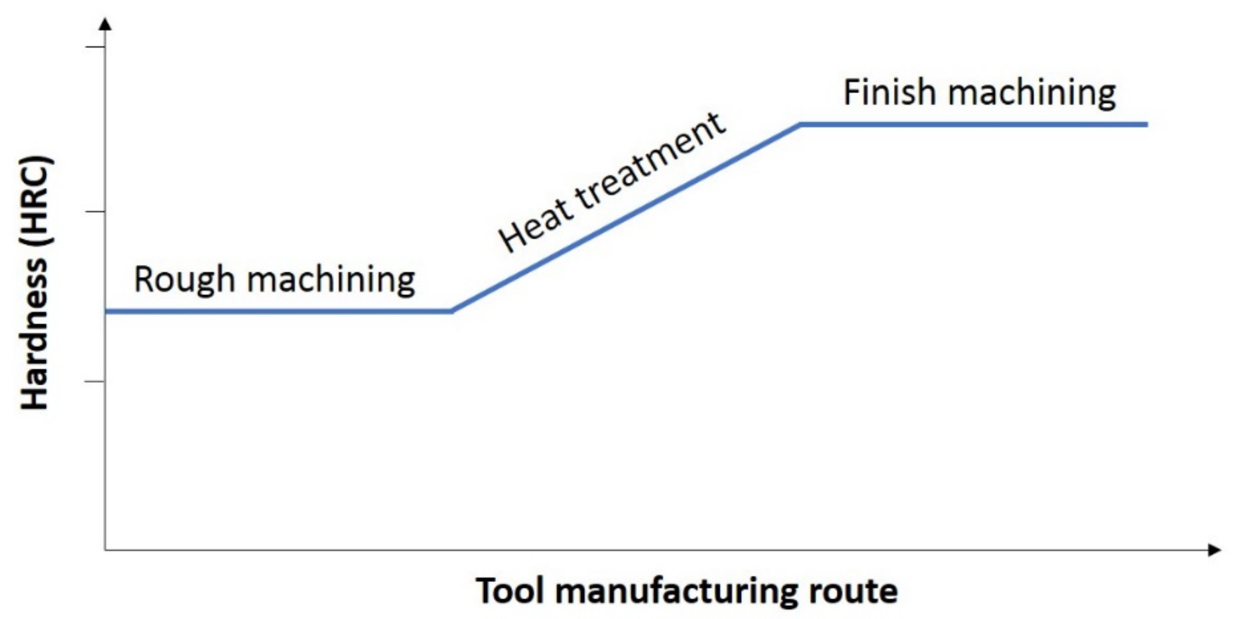
The regular manufacturing route for producing forming dies consists of the following steps: (i) tool steel in the soft annealed condition (low hardness) is rough machined to a geometry that is close to the desired final dimensions; (ii) the tool is then subjected to a hardening heat treatment (via quenching and tempering) that yields a high working hardness; and (iii) the tool undergoes a finish machining operation to remove the distortions and surface oxidation that occur during the heat treatment (Figure 1). Normal practice includes leaving some machining allowance on the die prior to hardening in order to adjust the tool to the final dimensions via (for example) grinding, electrical discharge machining, or hard milling. The distortions result from the stresses (e.g., machining stresses, thermal stresses, and transformation stresses) generated in the material during the heat treatment.
Uneven heating can result in local variations in volume, thereby contributing to distortion. Furthermore, the austenite to martensite phase transformation leads to a volume increase and, in turn, transformation stresses (Figure 2). In the case of tool steels, the martensite transformation starts and finishes at temperatures referred to as the martensite start temperature (Ms) and the martensite finish temperature (Mf), respectively. The volume expansions at Ms temperatures in iron–carbon alloys vary linearly from 2.0% at 0.19 wt % carbon to 3.1% at 1.01 wt % carbon [2].
In addition, at the level of the microstructural characteristics, some specific tool steels retain some austenite after quenching and even after tempering. Several tempering treatments and/or deep cryogenic treatments (down to liquid nitrogen temperatures of −195 °C) can be used to transform this retained austenite (RA) into martensite [4,5]. Thus, RA occurs when the steel is quenched to temperatures higher than the Mf temperature. Because the Mf of alloys containing more than 0.30% carbon is lower than room temperature, significant amounts of untransformed austenite, or RA, may be present (i.e., intermingled with martensite at room temperature) after quenching. Hot-work AISI H13 tool steel in the as-quenched condition contains a certain amount of RA. A previous study [6] has shown that cryogenically treating AISI H13 after a quenching and tempering treatment improves the performance of this steel. This improvement can be attributed to the transformation of RA to martensite and increased uniformity and homogeneity of the carbide distribution owing to secondary carbide precipitation [6]. The microstructural change induced by the RA transformation increases the dimensional distortions because the volume occupied by the martensitic microstructure is slightly larger than that of the replaced austenite.
Expensive finish machining operations are required for correcting the set of volumetric distortions induced by heat treatments and achieving the final desired dimensions of the forming die. Chip removal finish machining operations of high-hardness materials are very demanding processes in terms of cutting conditions due to the high friction and cutting forces involved. In general, the machining costs increase with increasing material hardness owing to the strategies needed to compensate for the stresses, wear, and deformation induced during the chip removal. In fact, tooling costs account for 5–30% of the total manufacturing costs [7]. Cost-effective alternatives, which overcome at least some of the drawbacks associated with manufacturing high-hardness forming tools, are therefore desirable.
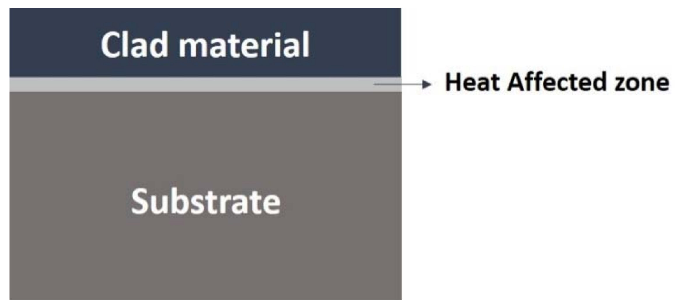
In this context, laser cladding technology applied to tool steel is being increasingly explored for die manufacturing. This increase is related to the applicability of cladding technology to several sectors, such as the metal coatings industry, the repair of high-cost components, the prototyping of parts, and applications characterized by low manufacturing volume [8]. In addition, this technology yields coatings with a low dilution, minimum distortion, a good metallurgical bond, a thin Heat-Affected Zone (HAZ), and good surface quality [8,9,10] (Figure 3). Furthermore, the rapid heating and cooling characteristics of the laser cladding process generate fine-grained microstructures that are more homogeneous than those comprising the equivalent forged steel [11]. The use of laser cladding is therefore expected to yield an improvement in the die service life. That is, laser cladding results in higher hardness (even without tempering of the clad layer) and more desirable microstructures than those of the forged steel.
Laser cladding technology allows for the design of a high-hardness layer, which is in contact with the work piece lying above a higher-toughness steel backup. This deposition technology has been successfully applied to the cutting, forming, and stamping of dies. In addition, laser cladding allows for the use of a low-hardness, high conductivity base metal, as in the case of copper with abrasion-resistant surface deposition [12]. Nevertheless, improvements are required as highly alloyed steels, which often require post-processing, can alter the substrate properties [13].
The wear behaviour of forged, quenched, and tempered AISI H13 has been compared with that of AISI H13 obtained via laser cladding (as-clad) and deposition after a conventional tempering treatment (as-clad + tempering). The lowest wear rate and therefore the best behaviour was obtained for the as-clad state of the material. Compared with that of the as-clad state, a slightly higher wear rate was achieved for the as-clad + tempered state. The highest rate was obtained for the forged AISI H13 steel subjected to a hardening and tempering treatment. Therefore, compared with forged AISI H13, the as-clad and the as-clad + tempered materials undergo lower amounts of wear. This is attributed to the (i) increase in hardness and (ii) uniformity as well as integrity of the microstructure resulting from laser cladding. The similarity in the behaviour of the as-clad and the as-clad + tempered states is attributed to the similar microstructures and levels of hardness occurring in these materials. However, the wear resistance of the as-clad material is somewhat higher than that of the as-clad + tempered state, owing possibly to the higher average hardness of the as-clad state [13].
In the present work, an alternative manufacturing route is proposed for forming dies based on laser cladding and cryogenic treatment of a high wear-resistant tool steel. The steel has been modified with the aim of increasing the amount of as-clad RA and, in turn, reducing the intensity of the finish machining operations without sacrificing wear resistance and toughness. This strategy targets high volume production runs, where the relatively high cost of nonconventional production routes can be compensated for by the attained die life extension.
2. Materials and Methods
2.1. Experimental Materials and Specimens
The study was performed on a hot-work AISI H13 tool steel alloyed with chromium–molybdenum–vanadium. This steel exhibits good abrasion resistance, high toughness and ductility, good high-temperature strength, and resistance to thermal fatigue. The AISI H13 is one of the tool steels most widely used for manufacturing tools in the forming and casting industry [13].
In the present study, the AISI H13 steel was modified with nickel (Ni) in order to induce RA formation and, via cryogenic treatment, RA transformation. As reported in a previous study, the amount of RA depends on the carbon content, alloy content (especially Ni and manganese), quenching temperature, and subsequent thermal and/or mechanical treatments [8]. In the case of AISI H13, deposition performed in a single pass (single-track laser cladding) yields a microstructure consisting of austenite dendrites retained in a matrix of martensite and carbides (hardness: 610–630 HV). In this case, the hardness of the surface manufactured via laser cladding is 45% higher than that of the substrate composed of quenched and tempered AISI H13 steel [10].
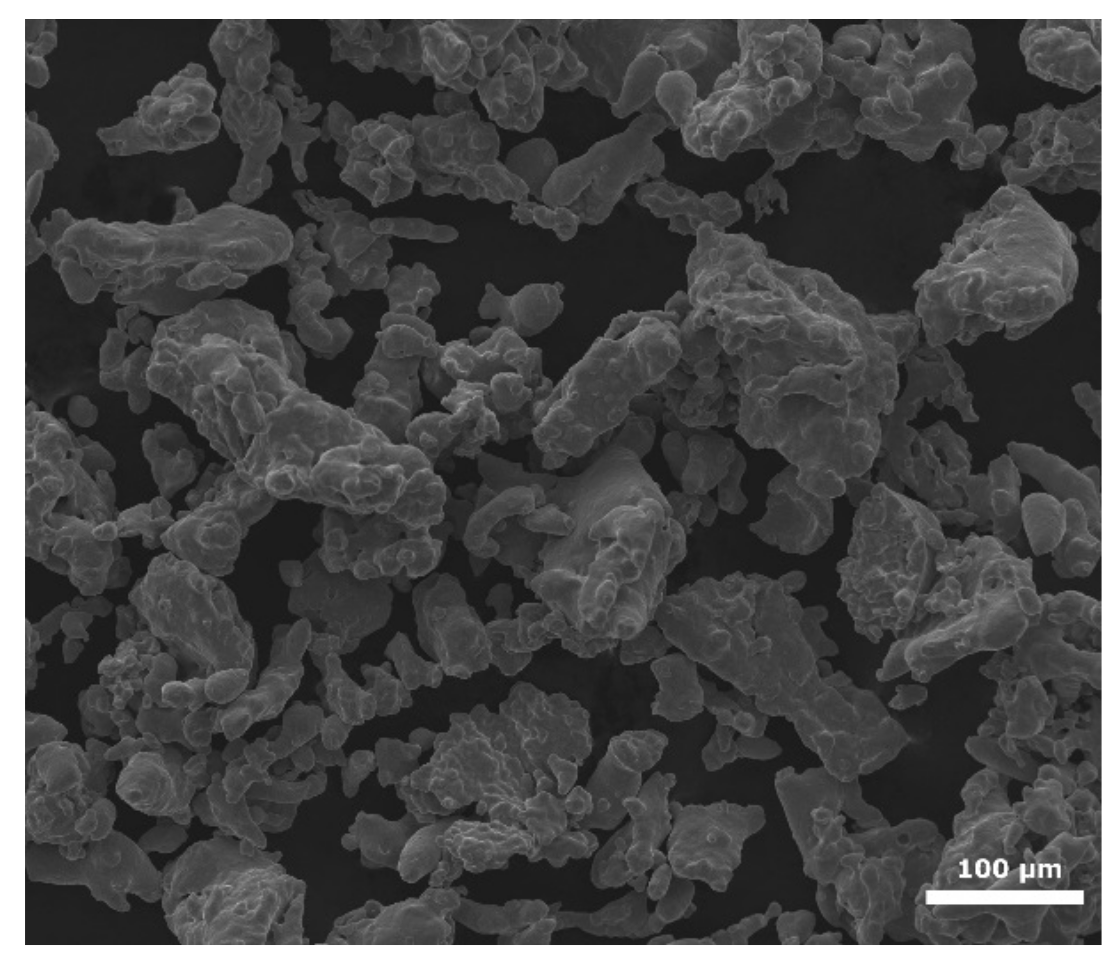
Moreover, the addition of Ni may lead to a decrease in the cracking tendency of the clad material during the laser cladding operations. In the present work, the samples were manufactured (by powder manufacturer Höganäs AB) from water-atomized AISI H13 with powder particle sizes ranging from 50 µm to 100 µm (Figure 4). The chemical composition of the raw material (with Fe balanced, see Table 1) was verified via inductively coupled plasma atomic emission spectroscopy (ICP-OES). The determined composition lies within the range of H13 based on the ASTM A-681 standard. AISI H13 samples with Ni additions of 1%, 2%, and 3% were designated as Sample A, Sample B, and Sample C, respectively.
The coatings were deposited onto a substrate plate of quenched and tempered AISI H13 steel with a tempered martensitic microstructure. The plate was subjected to the heat treatment described in Table 2. Austenitizing and tempering times of 30 min and 120 min, respectively, were employed. The nominal chemical composition of the AISI H13 (provided by material suppliers) and the final tool hardness are given in Table 3.
2.2. Laser Cladding
A 2.2 kW diode-pumped Nd:YAG laser was used during the cladding process. The laser beam was guided to the working region using an optical fiber and through a coaxial cladding head. Three coating samples with different proportions of Ni (1%, 2%, and 3%) were produced using the parameters shown in Table 4. Ten overlapped tracks were deposited for each coating.
The amount of Ni in each coating was verified via Spark Emission Spectroscopy, which was used to determine the chemical composition (with Fe balanced, see Table 5). The results confirmed that, during manufacture of the coating, the Ni addition error was kept below 0.1% in each sample.
2.3. Cryogenic Treatment
2.4. Characterization
Samples in the as-clad (AC) condition and after the cryogenic treatment (CR) were characterized via optical microscopy Leica MEF4 (Leica Microsystems, Wetzlar, Germany) and Rockwell C hardness measurements (in accordance with UNE-EN ISO 6507-1). The microstructure of the clad material, HAZ, and base material was analyzed, and the hardness measurements were performed on the top of the clad material. For the metallographic examination, samples were prepared using conventional metallographic methods that included grinding, polishing, and etching.
The occurrence and possible transformation of RA during the cryogenic treatment were evaluated via X-ray diffraction (XRD) measurements of the clad materials.
XRD patterns of the samples were obtained for crystallographic planes corresponding to ferrite and austenite phases. Continuous scans were performed over 2θ ranging from 55° to 120° using Cr Kα radiation at 35 kV, 45 mA (D8 Advance Vårio diffractometer, Bruker, Billerica, MA, USA). Measurements of the RA were performed in accordance with the ASTM E975 standard. In the case of steels, the amount of RA can be calculated from the integrated intensity of XRD peaks corresponding to the ferrite and austenite phases. The volume fraction of RA may be calculated from:
where Vγ is the volume fraction of austenite associated with the ratio of the measured integrated intensities of ferrite and austenite peaks to the R-value.
Vγ = (Iγ/Rγ)/[(Iα/Rα) + (Iγ/Rγ)]
3. Results and Discussion
3.1. Microstructure
The microstructure of the three constituent regions (clad material, HAZ, and base material) is analyzed for both conditions (AC and CR) of each sample. This analysis is performed in a polished section perpendicular to the plane housing the cladding layers. The microstructure is revealed via electrolytic etching with nital 4% acid (4% nitric acid and ethanol).
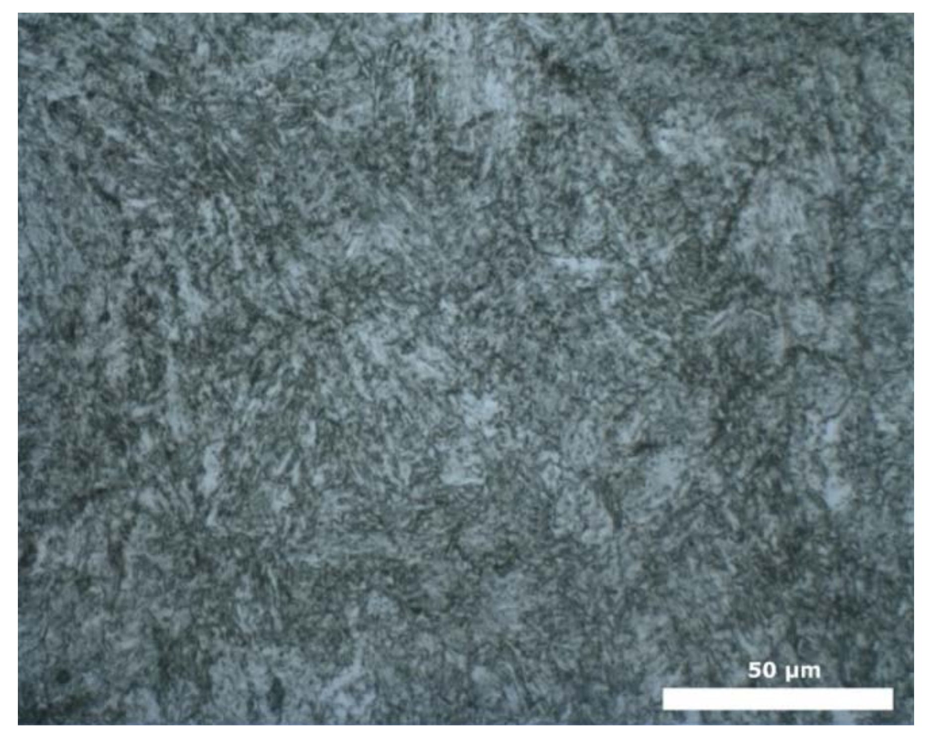
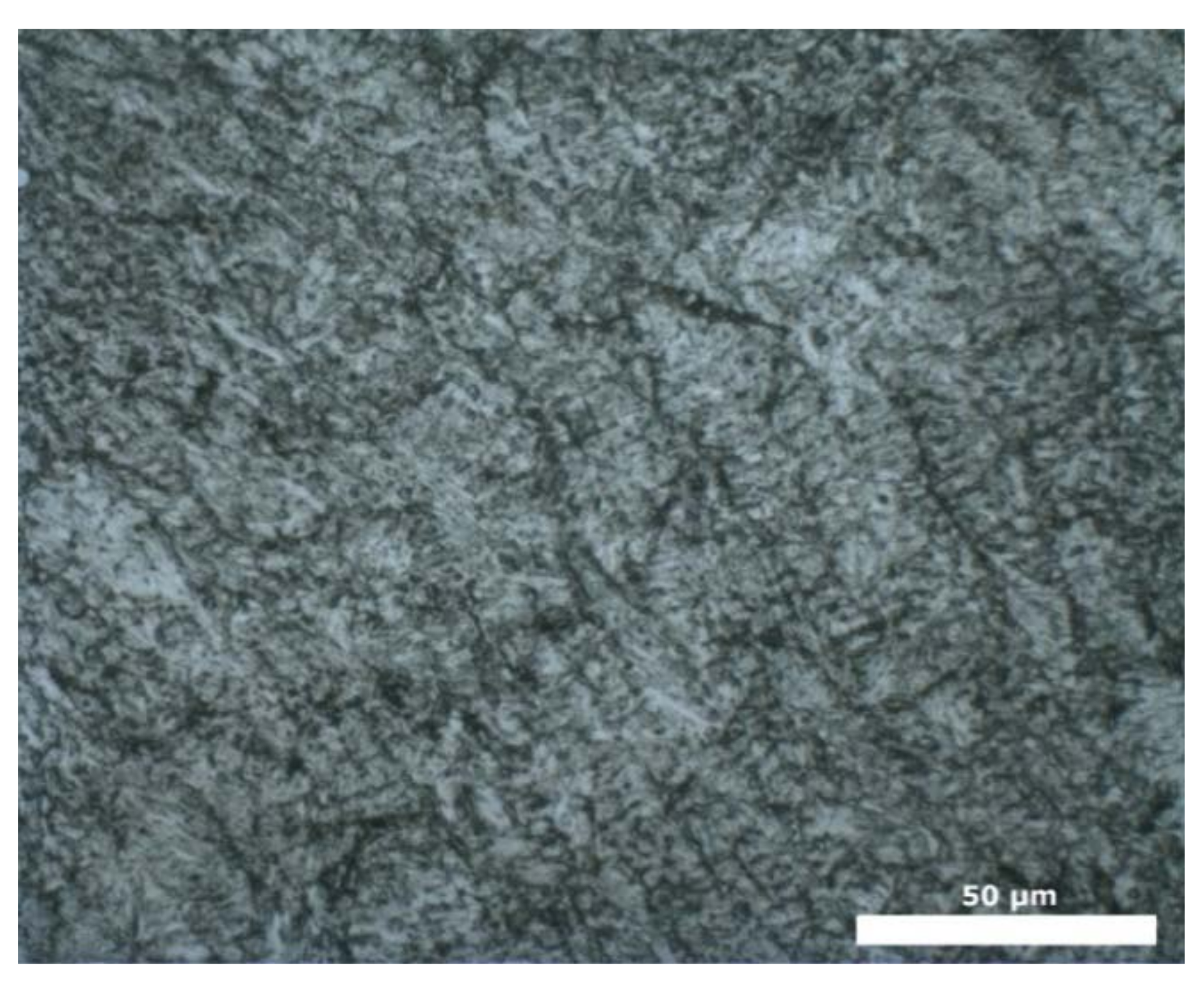
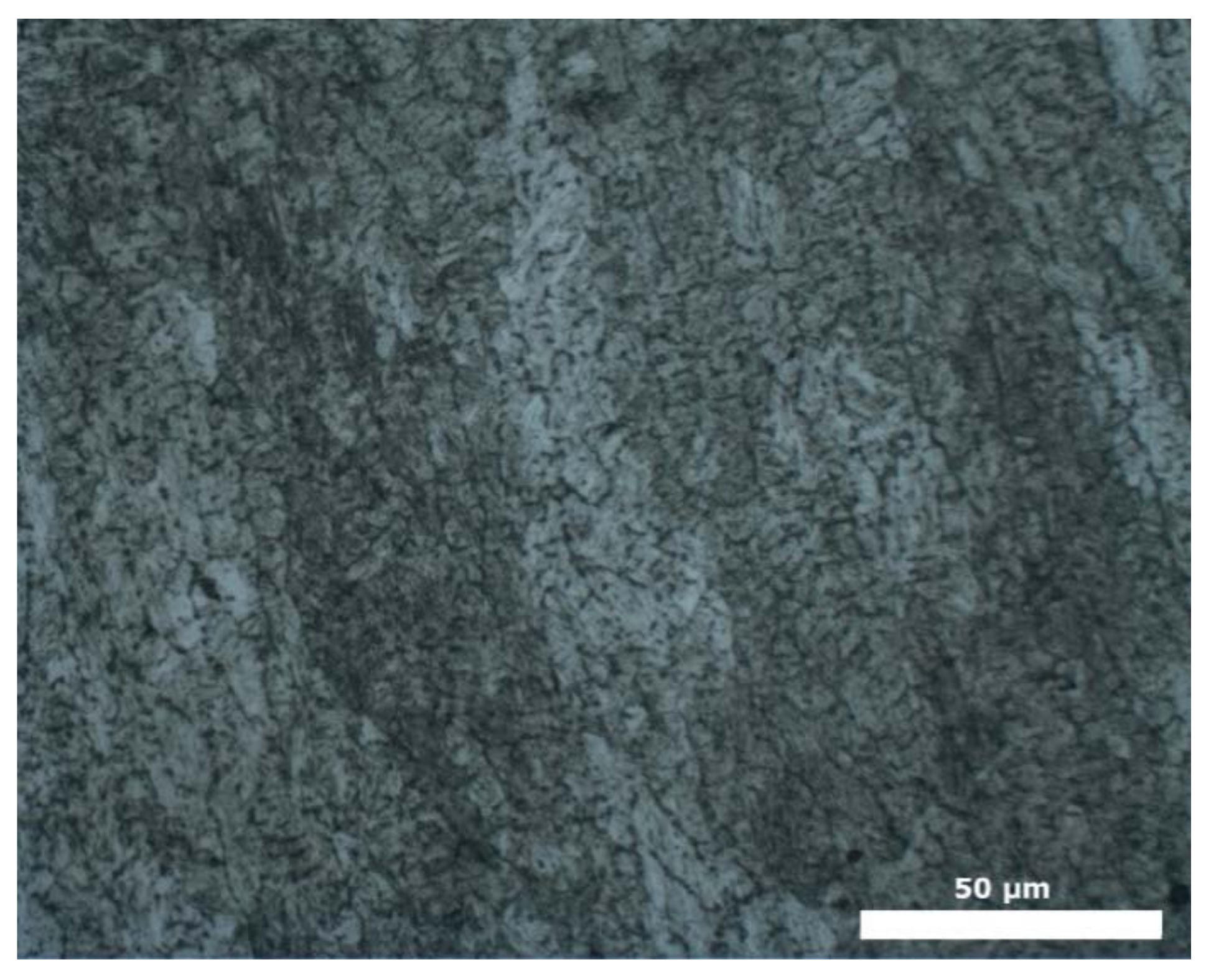
The microstructure comprising the clad material of the samples is composed of a martensitic matrix and carbides (Figure 7, Figure 8 and Figure 9). Retained austenite is absent from this microstructure (or remains unrevealed after etching). As mentioned in previous studies [13,15], large amounts of RA (>15%) can be detected via optical microscopy. However, special equipment and techniques, such as X-ray diffraction methods, are required for accurate measurements of low RA amounts. These methods can resolve austenite contents as low as 0.5%. In the present study, the HAZ and the base material were (in all cases) composed of bainitic and tempered martensite, respectively.
The residual stress in the finished components is of immense importance. Laser cladding inevitably introduces residual stresses in both clad and substrate. The tensile residual stresses in the clad could adversely affect the mechanical performance of the substrate being deposited. In order to determine the role of residual stresses, X-ray diffraction or alternative techniques can be used [16,17].
3.2. Hardness
For both the AC and CR conditions, the hardness measurements were performed in the plane housing the cladding layers. The average of five measurements on each sample is shown in Table 6.
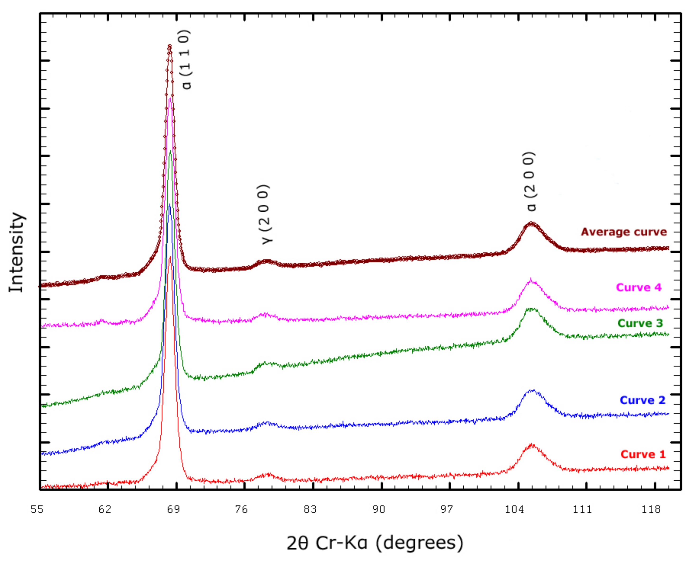
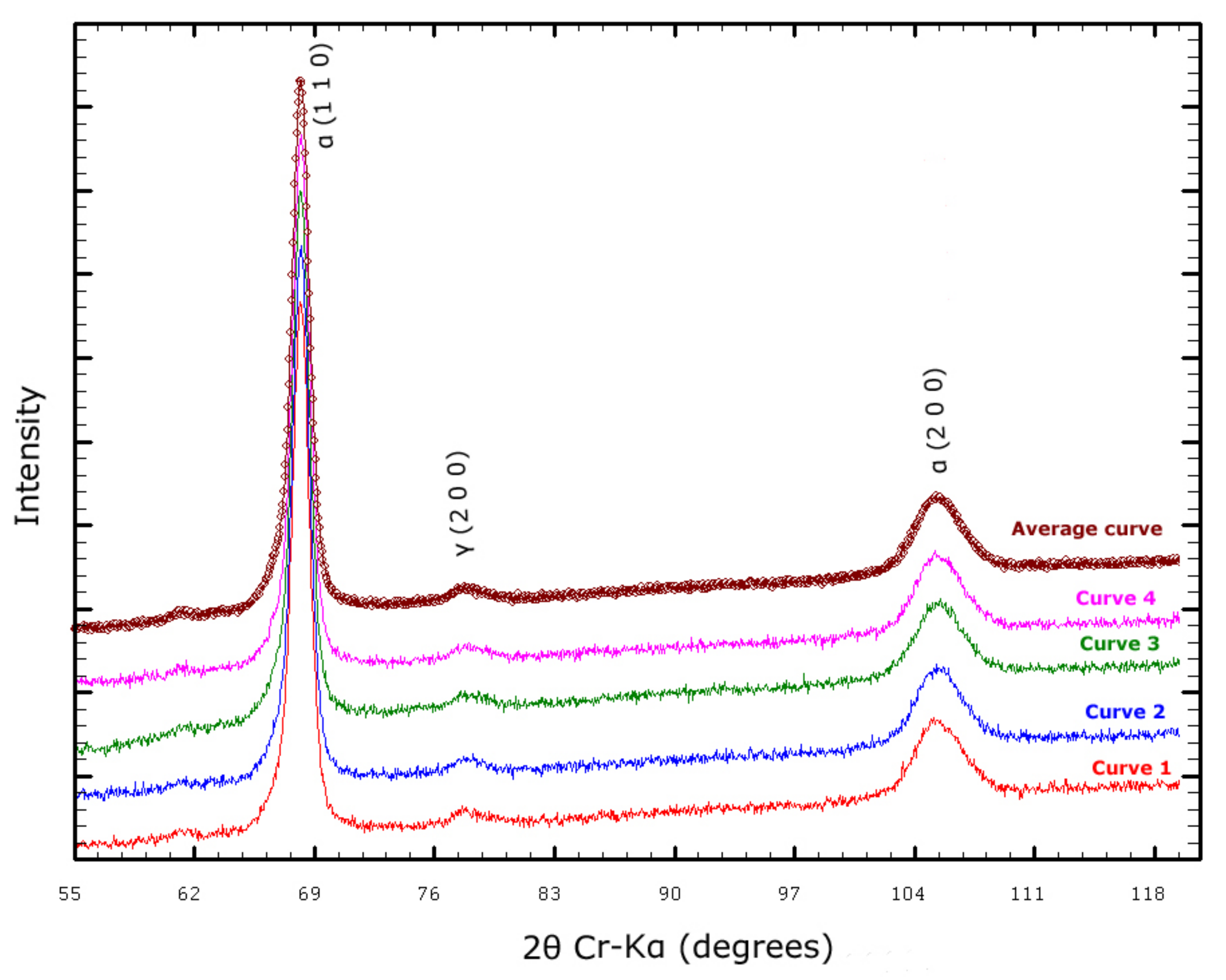
3.3. X-ray Diffraction
The measured hardness values indicated that a 2% Ni content (sample B) represents the most convenient solution: this content when reduced to 1% yielded harder finishing (than that occurring at 2%), and when increased to 3% increased raw material costs with no apparent benefits in terms of machining and working hardness. Thus, the austenite volume fraction of the clad material from Sample B in the AC and CR conditions was measured via XRD to verify that the hardening was induced by the formation of martensite from RA. Four measurements were performed for each condition (see Figure 10 and Figure 11). As the figures show, peaks occur at 2θ angles of 68.94°, 106.35°, and 79.19° corresponding to the (110) and (200) planes of the ferrite phase and (200) plane of the austenite phase, respectively.
The integrated intensities of the peaks corresponding to the planes of the ferrite and austenite phases were compared. The XRD patterns revealed that the volume fraction of RA decreased with cryogenic treatment (austenite peaks occurred with lower intensity in the CR sample than in the AC sample). Furthermore, the volume fraction of austenite was determined by comparing the integrated XRD intensity of the ferrite and austenite phases. The results are shown in Table 7. The calculations were obtained from Equation (1) and the Rγ and Rα values are 34.78 and 20.73, respectively.
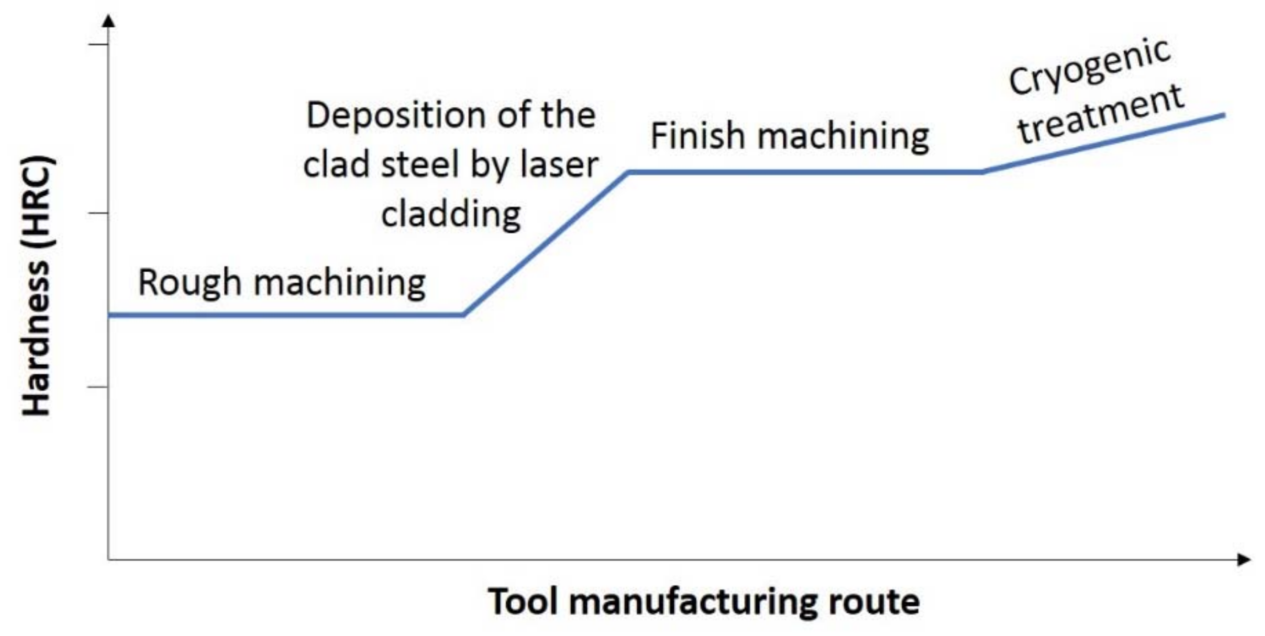
3.4. Proposed Manufacturing Route of Forming Tools
A new manufacturing route is proposed based on the developments shown in this work (Figure 12). This route was based on laser cladding and cryogenic treatment of a high wear-resistant tool steel that had been modified with the aim of (i) increasing the amount of as-clad RA and, in turn, (ii) reducing the intensity of the finish machining operations without sacrificing wear resistance and toughness. The volume expansion during the transformation of RA into martensite could also promote a beneficial compressive residual stresses field in the coating.
4. Conclusions
The results obtained in the present experimental work indicated that RA occurrence in tool steel during laser cladding can be controlled by (i) tuning the austenite-stabilizing element content of the alloy and then (ii) increasing the hardness level of the clad material through a cryogenic treatment. The as-deposited AISI H13 steel with 2% Ni had a hardness of 52 ± 1.5 HRC, which increased to 58 ± 1.5 HRC with cryogenic treatment of the material. Moreover, the XRD-determined amounts of RA confirmed that the hardness-increasing mechanism was correlated with the RA transformation occurring during this treatment.
The combination of laser cladding and deep cryogenic treatments led to a new manufacturing process that yielded balance between hardness and machinability, which is intermediate between those of carbide-based tool steels and precipitation-hardening (PH) steels.
Author Contributions
All of the five authors conceived, designed, and interpreted the results; M.M. and G.A. determined the metallurgical characteristics and performed the cryogenic treatment; J.L. and C.S. manufactured the samples using laser cladding technology; and M.M., G.A., and C.A. wrote the paper.
Funding
The authors gratefully acknowledge the funding provided by the Department of Research and Universities of the Basque Government under Grant No. IT947-16 and the University of the Basque Country UPV/EHU under Program No. UFI 11/29.
Conflicts of Interest
The authors declare no conflict of interest.
References
- Roberts, G.; Krauss, G.; Kennedy, R. Tool Steels, 5th ed.; ASM International: Almere, The Netherlands, 1998; ISBN 978-0-87170-599-0. [Google Scholar]
- Moyer, J.M.; Ansell, G.S. The volume expansion accompanying the martensite transformation in iron-carbon alloys. Metall. Trans. A 1975, 6, 1785–1791. [Google Scholar] [CrossRef]
- Deng, D. FEM prediction of welding residual stress and distortion in carbon steel considering phase transformation effects. Mater. Des. 2009, 30, 359–366. [Google Scholar] [CrossRef]
- Yan, G.; Huang, X.; Wang, Y.; Qin, X.; Yang, M.; Chu, Z.; Jin, K. Effects of heat treatment on mechanical properties of H13 steel. Met. Sci. Heat Treat. 2010, 52, 393–395. [Google Scholar] [CrossRef]
- Gill, S.S.; Singh, J.; Singh, R.; Singh, H. Metallurgical principles of cryogenically treated tool steels—A review on the current state science. Int. J. Adv. Manuf. Technol. 2011, 54, 59–82. [Google Scholar] [CrossRef]
- Çiçek, A.; Kara, F.; Kivak, T.; Ekici, E.; Uygur, I. Effects of deep cryogenic treatment on the wear resistance and mechanical properties of AISI H13 hot-work tool steel. J. Mater. Eng. Perform. 2015, 24, 4431–4439. [Google Scholar] [CrossRef]
- Ahn, D.G. Hardfacing technologies for improvement of wear characteristics of hot working tools: A Review. Int. J. Precis. Eng. Manuf. 2013, 14, 1271–1283. [Google Scholar] [CrossRef]
- Jayakumar, K.; Senthil kumar, T.; Shanmugarajan, B. Review study of laser cladding processes on ferrous substrates. Int. J. Adv. Multidiscip. Res. 2015, 2, 72–87. [Google Scholar]
- Leunda, J.; García Navas, V.; Soriano, C.; Sanz, C. Effect of laser tempering of high alloy powder metallurgical tool steels after laser cladding. Surf. Coat. Technol. 2014, 259, 570–576. [Google Scholar] [CrossRef]
- Telasang, G.; Dutta Majumdar, J.; Padmanabham, G.; Tak, M.; Manna, I. Effect of laser parameters on microstructure and hardness of laser clad and tempered AISI H13 tool steel. Surf. Coat. Technol. 2014, 258, 1108–1118. [Google Scholar] [CrossRef]
- Niu, H.J.; Chang, I.T.H. Microstructural evolution during laser cladding of M2 high-speed steel. Metall. Mater. Trans. A 2000, 31, 2615–2625. [Google Scholar] [CrossRef]
- Kolleck, R.; Pfanner, S.; Kassegger, H.; Lind, C. Technology update-“forming technology and vehicle safety”. In Proceedings of the 2nd International Conference on: Deformation Processing and Structure of Materials, Belgrade, Serbia and Montenegro, 26–28 May 2005; pp. 69–75. [Google Scholar]
- Telasang, G.; Dutta Majumdar, J.; Wasekar, N.; Padmanabham, G.; Manna, I. Microstructure and mechanical properties of laser clad and post-cladding tempered AISI H13 tool steel. Metall. Mater. Trans. A 2015, 46, 2309–2321. [Google Scholar] [CrossRef]
- Alava, L.A.; Artola, G.; Guinea, I.; Muro, M. On the influence of cryogenic steps on heat treatment processes. Mater. Perform. Charact. 2017, 6, 837–849. [Google Scholar] [CrossRef]
- Hidalgo, J.; Findley, K.O.; Santofimia, M.J. Thermal and mechanical stability of retained austenite surrounded by martensite with different degrees of tempering. Mater. Sci. Eng. A 2017, 690, 337–347. [Google Scholar] [CrossRef]
- Suresh, S.; Giannakopoulos, A.E. A new method for estimating residual stresses by instrumented sharp indentation. Acta Mater. 1998, 46, 5755–5767. [Google Scholar] [CrossRef]
- Ghidelli, M.; Marco Sebastiani, M.; Collet, C.; Guillemet, R. Determination of the elastic moduli and residual stresses of freestanding Au-TiW bilayer thin films by nanoindentation. Mater. Des. 2016, 106, 436–445. [Google Scholar] [CrossRef]
Figure 1.
Regular manufacturing route of forming tools.

Figure 2.
Schematic of volume change induced by the phase transformation (adapted from [3]).
Figure 2.
Schematic of volume change induced by the phase transformation (adapted from [3]).

Figure 3.
Identification of the substrate, heat-affected zone (HAZ), and clad material.

Figure 4.
AISI H13 powder particles employed as raw material for manufacturing the samples.

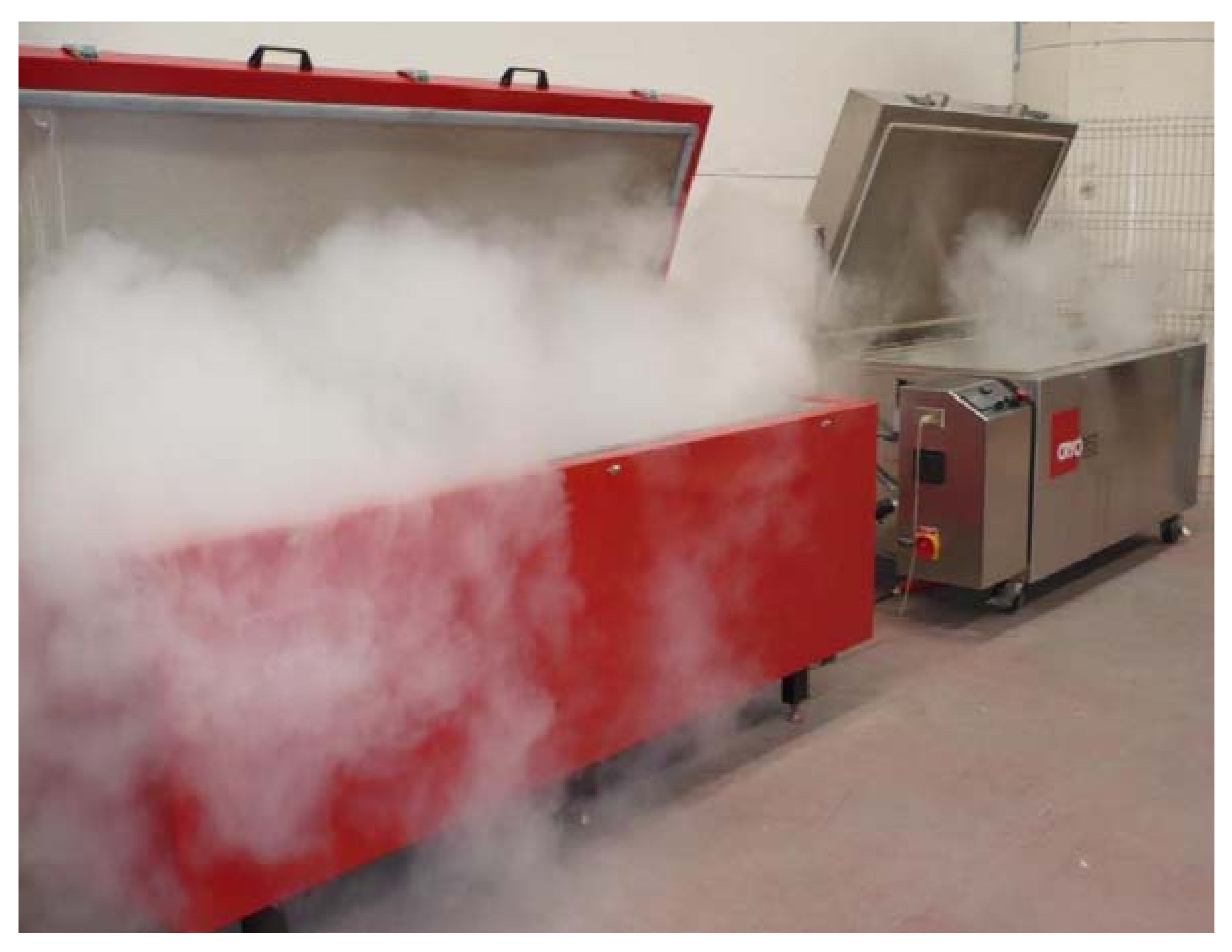
Figure 5.
Cryogenic processors in IK4-Azterlan.

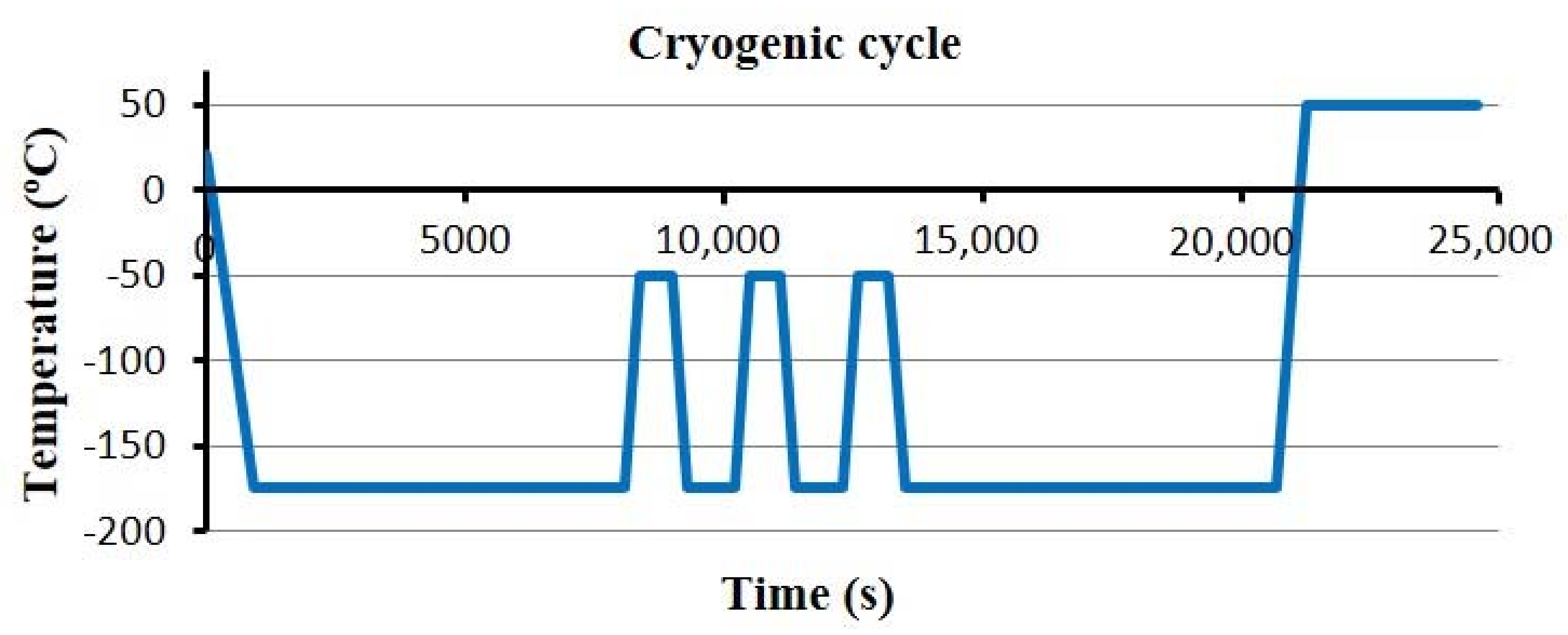
Figure 6.
The applied multistage cryogenic cycle.

Figure 7.
The microstructure of sample A.

Figure 8.
The microstructure of sample B.

Figure 9.
The microstructure of sample C.

Figure 10.
XRD patterns of sample AISI H13 in the AC condition.

Figure 11.
XRD patterns of sample AISI H13 in the CR condition.

Figure 12.
Proposed manufacturing route of forming tools.


Table 1.
Chemical composition of the AISI H13 powder (wt %).
| Material | C | Si | Mn | P | S | Cr | Mo | V | Ni |
|---|---|---|---|---|---|---|---|---|---|
| ASTM A681 Specification | 0.32–0.45 | 0.80–1.20 | 0.20–0.50 | ≤0.03 | ≤0.03 | 4.75–5.50 | 1.10–1.75 | 0.80–1.20 | ≤0.03 |
| AISI H13 Powder | 0.37 | 1.15 | 0.21 | 0.015 | 0.006 | 5.25 | 1.60 | 0.98 | 0 |
| Measurement uncertainty KI = 2 | ±0.01 | ±0.04 | ±0.01 | ±0.01 | ±0.01 | ±0.01 | ±0.05 | ±0.004 | ±0.01 |
Table 2.
Heat treatment of AISI H13.
| Material | Hardening Treatment | |||
|---|---|---|---|---|
| Austenitizing | Tempering | |||
| Temperature (°C) | Time (min) | Temperature (°C) | Time (min) | |
| AISI H13 | 1030 | 30 | 610 | 120 |
Table 3.
Chemical composition (wt %) and hardness of the AISI H13 plate.
| Material | C | Si | Mn | Cr | Mo | V | Hardness (HRC) | Hardness (HV) |
|---|---|---|---|---|---|---|---|---|
| AISI H13 Substrate | 0.40 | 0.85 | 0.45 | 5.15 | 1.25 | 0.9 | 51 | 527 |
| Measurement uncertainty KI = 2 | ±0.01 | ±0.04 | ±0.01 | ±0.01 | ±0.05 | ±0.004 | ±1.5 | ±13 |
Table 4.
Process parameters for producing crack-free coatings.
| Process Parameters | |
|---|---|
| Power (kW) | 1.5 |
| Scanning speed (mm/min) | 900 |
| Spot diameter (mm) | 2.7 |
| Powder feed rate (g/min) | 20 |
| Overlap distance (mm) | 1.0 |
| Shielding gas | Ar |
| Shielding gas flow (L/min) | 20 |
Table 5.
Chemical composition of AISI H13 (wt %).
| Material | C | Si | Mn | P | S | Cr | Mo | V | Ni |
|---|---|---|---|---|---|---|---|---|---|
| Sample A | 0.37 | 1.14 | 0.21 | 0.010 | 0.010 | 5.20 | 1.58 | 0.97 | 0.99 |
| Sample B | 0.36 | 1.13 | 0.21 | 0.010 | 0.010 | 5.15 | 1.57 | 0.96 | 1.96 |
| Sample C | 0.36 | 1.12 | 0.21 | 0.010 | 0.010 | 5.10 | 1.55 | 0.95 | 2.91 |
| Measurement uncertainty KI = 2 | ±0.01 | ±0.04 | ±0.01 | ±0.01 | ±0.01 | ±0.01 | ±0.05 | ±0.004 | ±0.01 |
Table 6.
Average hardness of the clad material (Rockwell C).
| Material | AC | CR |
|---|---|---|
| Sample A | 56 | 59 |
| Sample B | 52 | 58 |
| Sample C | 52 | 58 |
| Measurement uncertainty KI = 2 | ±1.5 | ±1.5 |
AC, as-clad; CR, cryogenic treatment.
Table 7.
Integrated intensity of austenite and ferrite in plane (200), and the volume fraction of retained austenite.
Table 7.
Integrated intensity of austenite and ferrite in plane (200), and the volume fraction of retained austenite.
| Material | Iγ (200) | Iα (200) | Vγ | Retained Austenite (%) |
|---|---|---|---|---|
| AISI H13 (AC) | 3324.09 | 21,414.53 | 0.0847 | 9 |
| AISI H13 (CR) | 2502.54 | 23,009.02 | 0.0609 | 6 |
© 2018 by the authors. Licensee MDPI, Basel, Switzerland. This article is an open access article distributed under the terms and conditions of the Creative Commons Attribution (CC BY) license (http://creativecommons.org/licenses/by/4.0/).
Share and Cite
MDPI and ACS Style
Muro, M.; Artola, G.; Leunda, J.; Soriano, C.; Angulo, C. Retained Austenite Control for the Soft Machining of High-Hardness Tool Steels. Metals 2018, 8, 564. https://doi.org/10.3390/met8070564
AMA Style
Muro M, Artola G, Leunda J, Soriano C, Angulo C. Retained Austenite Control for the Soft Machining of High-Hardness Tool Steels. Metals. 2018; 8(7):564. https://doi.org/10.3390/met8070564
Chicago/Turabian StyleMuro, Maider, Garikoitz Artola, Josu Leunda, Carlos Soriano, and Carlos Angulo. 2018. "Retained Austenite Control for the Soft Machining of High-Hardness Tool Steels" Metals 8, no. 7: 564. https://doi.org/10.3390/met8070564
Note that from the first issue of 2016, this journal uses article numbers instead of page numbers. See further details here.