Microstructure and Wear Resistance of Fe-Cr-Mo-Co-C-B Amorphous Composite Coatings Synthesized by Laser Cladding


State Key Laboratory of Tribology, Department of Mechanical Engineering, Tsinghua University, Haidian District, Beijing 100084, China
*
Author to whom correspondence should be addressed.
Metals 2018, 8(8), 622; https://doi.org/10.3390/met8080622
Submission received: 3 July 2018
/
Revised: 31 July 2018
/
Accepted: 3 August 2018
/
Published: 7 August 2018
(This article belongs to the Special Issue Additive Layer Manufacturing using Metal Deposition)
Abstract
:A novel amorphous composite coating was synthesized successfully on 3Cr13 stainless steel by laser cladding Fe-Cr-Mo-Co-C-B amorphous alloy powder. Scanning electron microscopy (SEM), energy dispersive spectroscopy (EDS), and X-ray diffraction (XRD) were used to analyze the microstructure, composition, and phase structure of the coatings. Hardness and friction wear testers were used to analyze the hardness and wear resistance of the coatings. Results show that the cladding layer has an amorphous/crystalline composite structure, which is composed of a columnar grain region at the bottom and an amorphous region in the upper layer. The solute redistribution between the coating and the substrate in the bonding zone and the lower cooling rate at bottom account for the occurrence of crystallization. The highest hardness of the cladding layer is 1179 , which is about 6 times that of the 3Cr13 stainless steel substrate (200 ). The cladding layer greatly improves the wear resistance of the substrate with a much lower coefficient of friction and wear mass loss compared with the substrate.
1. Introduction
Fe-based bulk amorphous alloys are gaining more and more attention due to their superior properties, such as higher hardness, higher wear resistance, higher corrosion resistance [1,2,3,4], and lower cost. However, their applications are restricted by poor tensile ductility and limited size when they are used in bulk form. Instead, amorphous coatings are prepared on surfaces of metallic components to avoid such shortcomings and to take advantage of superior wear and corrosion resistances. Various processes have been used to prepare Fe-based amorphous composite coatings, including high velocity oxygen fuel (HVOF) [5], high velocity air fuel (HVAF) [6], plasma spray [7], spark cladding [8], laser cladding [9,10,11,12], and so on. Laser cladding has high power densities ( W/) and cooling rates ( K/s), which can satisfy the need to form amorphous coatings [13]. Compared with other processes, laser cladding has the following advantages: firstly, the coating can form a good metallurgical bond with the substrate to ensure high strength; secondly, the coatings have a higher compactness and fewer porosity [14,15].
Different types of Fe-based amorphous alloys have been used to fabricate amorphous coatings by laser cladding. Wang et al. [16] cladded Fe-Cr-Si-P amorphous alloy on 304 L substrate. The results showed that the coating consisted of an amorphous phase and crystallization phases of Fe2Si, Fe3P, etc., and the coating had a high hardness, wear resistance, and corrosion resistance. The microhardness is about 8000 MPa; the and are –449.3 mV and 4.34 μA/, respectively; the frictions coefficient at the load of 100 N is 0.076. Basu et al. [17] attempted to prepare amorphous coatings by laser cladding bulk amorphous alloy powders on AISI4140 steel substrates. The process parameters of laser powers from 1.5 kW to 2.5 kW, and linear scan speeds from 2.5 to 4.5 mm/s were tried, but amorphous phases were not obtained in the coatings. With the high cooling rate in the cladding layer, as predicted by numerical simulations, the absence of an amorphous phase was mainly due to the fact that the composition of the cladding layer was diluted by the substrate in the bonding zone, which facilitated the nucleation and growth of grains. Wu et al. [18] developed amorphous layers of 1.2 mm thickness on AISI 1045 steel substrates using a high-power laser. The cladding layer has a fairly high proportion of amorphous phase. Zhu et al. [19] used low-purity materials to synthesize Fe-Ni-Si-B-V-M amorphous composite coatings by laser cladding, and found that multiple constituents (including Al, Ti, Mo, and C) could significantly affect the glass forming ability (GFA), which in turn affected coating performances. Balla et al. [20] used Fe-Cr-Mo-W-C-Mn-Si-B bulk amorphous alloy powders to synthesize coatings by Laser Engineered Net Shaping (LENS(tm)). The microstructure of the coating was an amorphous/crystalline composite structure. It was found that the crystallization phase in the coating might originate from the crystalline phase in the powder, and lower heat input favored the formation of amorphous phases. However, to our knowledge, there are no reports about the laser cladding of Fe-Cr-Mo-Co-C-B bulk amorphous alloy yet.
In this study, a new type of Fe-Cr-Mo-Co-C-B amorphous alloy powder, developed by Beijing Zhongji Amorphous Co., Ltd. (Beijing, China), was selected for laser cladding in this study. The composition of the powder is (wt. %), which has a high glass forming ability. It has been used to prepare coatings on steel surfaces by plasma spraying, which have high hardness, excellent wear resistance, and corrosion resistance. However, the powder has not been used in laser cladding before. Therefore, an exploratory study was carried out to prepare amorphous composite coatings. The microstructure, composition, phase, and properties of the cladding layer were studied.
2. Experimental
2.1. Laser Cladding Process
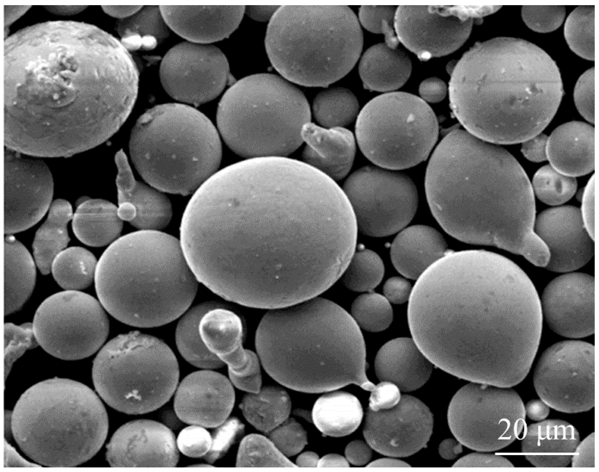
Fe-based amorphous alloy powders were prepared by vacuum gas atomization with a mixture of pure elemental powders of Fe, Mo, Cr, Co, C, and B (all with greater than 99.8 wt. % purity) with chemical composition of (wt. %). The particle size of the powder is 200–320 mesh and the powder appearance is shown in Figure 1. 3Cr13 stainless steel sheets with dimensions of 80 mm × 50 mm × 6 mm were used as substrates. The nominal composition of the 3Cr13 stainless steel is shown in Table 1. Before laser cladding, the substrates were smoothed with sandpaper, cleaned with acetone to remove the oil pollution on the surface, and finally dried in the air. The powder was dried at 120 °C for 2 h using a vacuum furnace.
A fiber laser processing system was used to prepare the coatings, which mainly consisted of an IPG YLS-2000W (IPG Photonics Corporation, Oxford, MA, USA) fiber laser and a DPSF-2 powder feeder (Beijing Aeronautical Manufacturing Technology Research Institute, Beijing, China) with a lateral nozzle. The spot size of the laser beam was 3 mm diameter circle and had a Gaussian energy distribution. Ar gas with a gas flow rate of 10 L/min was used to transport powder while protecting the melt pool from oxidation. A parameter study has been carried out with process parameters of laser power from 500 W to 2000 W and scanning speed from 2 mm/s to 20 mm/s, so as to obtain the optimal set of process parameters used in the present study. With the parameters, uniform coatings could be obtained with good metallurgical bonding at the coating/substrate interface and low dilution rates. The optimized process parameters used in the present study is shown in Table 2.
2.2. Phase and Microstructure Analysis
The samples were cut along the cross-section using the spark wire cutting method, and then were mechanically polished. After that, the samples were etched with the aqua regia and the microstructures were examined using a QUANTA 200 FEG scanning electron microscope (SEM) (FEI Company, Hillsboro, OR, USA). The element distributions were analyzed by the energy disperse spectroscopy (EDS) (FEI Company, Hillsboro, OR, USA). The cladding samples with surface size of 5 mm × 5 mm were polished with sandpaper to a distance of 0.4 mm from the top. Then the phase composition of the sample was obtained by a Bruker D8 X-ray diffractometer (Bruker Corporation, Karlsruhe, Germany) using Cu-Ka (λ = 0.154060 nm) radiation at 40 kV and 200 mA. A continuous scan mode was used to scan in a 2θ range of 20–80°. The scanning speed was 4° per minute at 0.02° per step.
2.3. Microhardness and Wear Tests
The microhardness was measured by a Vickers hardness tester (HM-800) (Mitutoyo Corporation, Tokyo, Japan) with a load of 500 g and a loading time of 15 s. The samples with a size of were cut from the 3Cr13 stainless steel substrate and the laser cladding specimens for the wear test. Both of the specimens were smoothed with a 1500 grit sandpaper. A ball-on-disc tribometer (type: UMT-3, Bruker Corporation, Karlsruhe, Germany) was used to test the wear resistance of the substrate and the cladding layer. The wear tests were conducted according to GB/T 12444-2006 standard. A 4 mm diameter silicon nitride ball with the hardness of 1550 was used as the upper specimen of wear test. The parameters of the wear test include: rotating diameter of 10 mm, rotating speed of 100 r/min, load of 2 N, and test time of 20 min. Scanning electron microscopy (SEM) (FEI Company, Hillsboro, OR, USA) and energy disperse spectroscopy (EDS) were used to analyze the worn surfaces and compositions in subsequence.
3. Results and Discussion
3.1. Phase and Microstructure
Figure 2a shows the X-ray diffraction patterns of Fe-based amorphous alloy powders. It can be observed from the figure that there is an obvious broad halo peak around the diffraction angle of 45° and 75° (2θ), and there are several weak peaks of crystalline phases. Therefore, the powders are mainly composed of amorphous an phase, together with a small amount of crystal phases.
Figure 2b shows the X-ray diffraction patterns of the multi-track laser cladding. A broad halo peak representing the amorphous phase can be observed around the diffraction angle of 45° (2θ). There were also several peaks of crystalline phases on the curve. The peaks of crystalline phases were identified as carbides , , and solid solution .
The Pseudo-Voigt function was used to fit the peaks of amorphous phases and crystalline phases, respectively, and the area of the peaks of amorphous phases and crystalline phases were calculated. The volume fraction of the amorphous phase was calculated using the following formula [21]:
By calculation, the volume fraction of the amorphous phase in the cladding layer obtained under the selected process parameters is about 52.8%, compared with 85.7% in the powder.
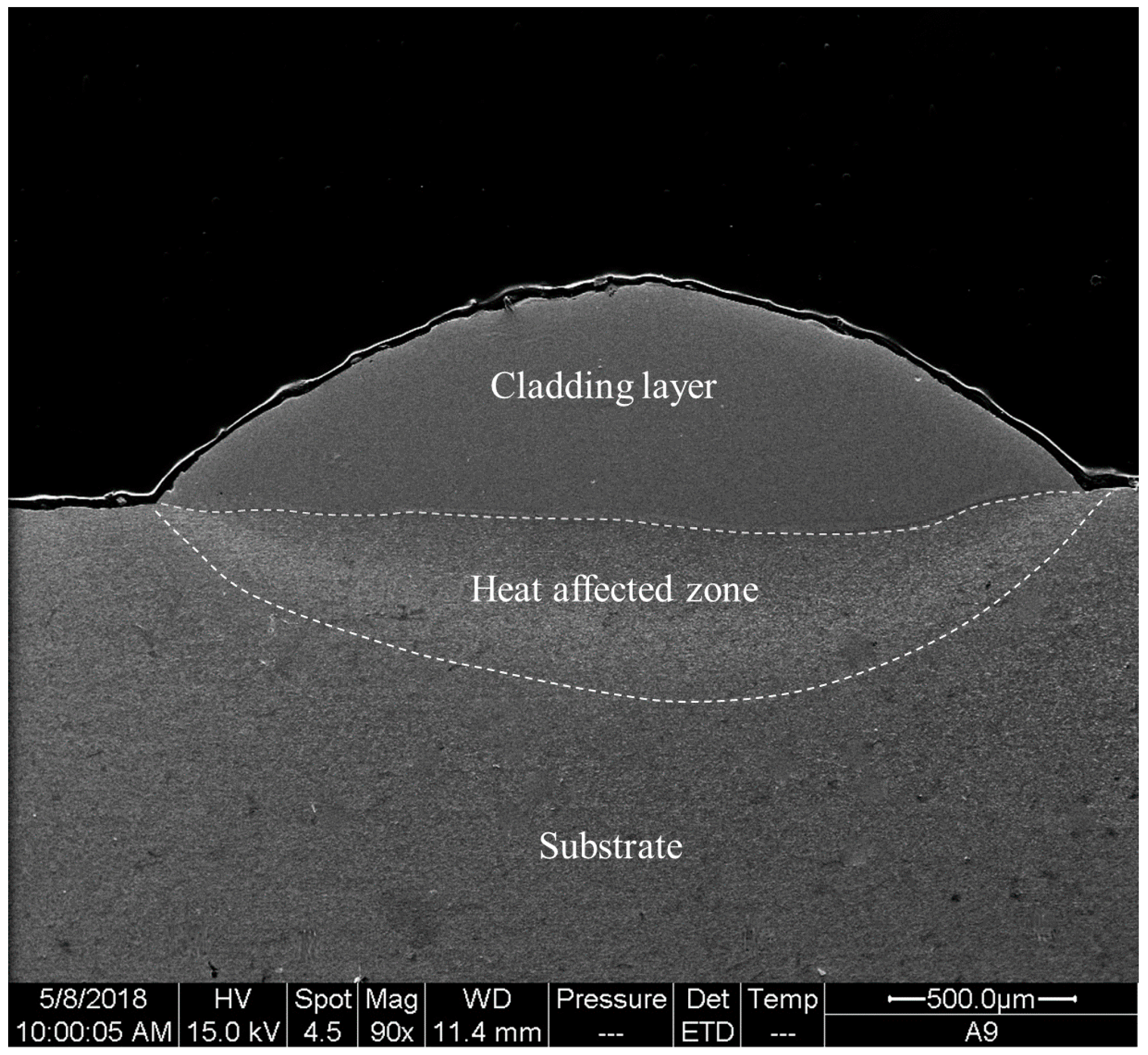
The cross-section morphology of the single-track laser cladding is shown in Figure 3. The surface of the cladding layer is smooth. The maximum thickness of the cladding layer is about 580 μm. Three distinct areas can be observed: the upper cladding layer, the heat affected zone in the middle, and the substrate at the bottom.
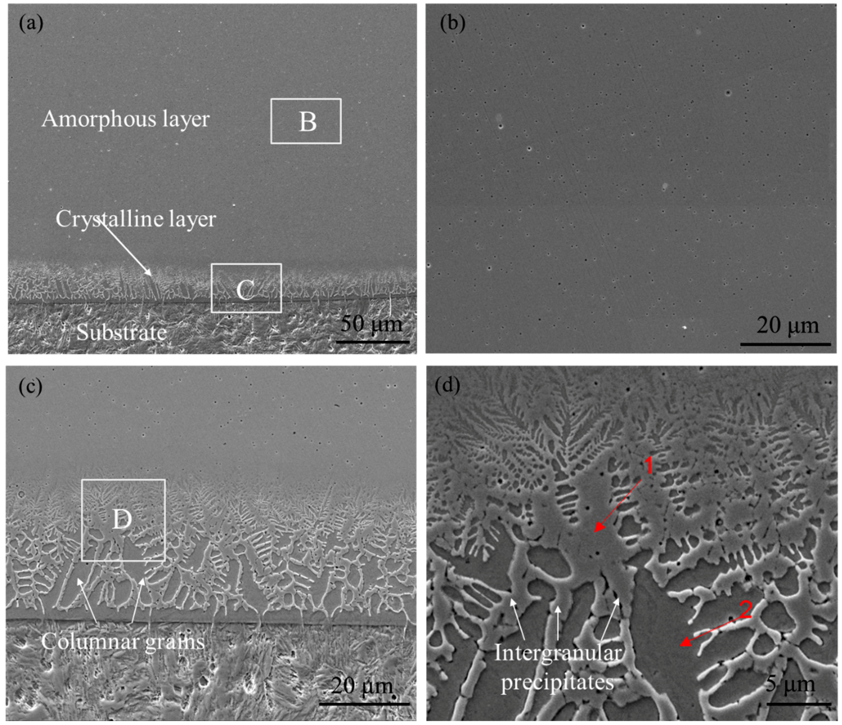
Figure 4 shows the microstructure of the single-track laser cladding. Figure 4a shows the layered structure of the cladding, which consists of a featureless region in the upper layer and a dendrite region in the bottom. Figure 4b is the magnification of area B in Figure 4a. Combined with the XRD test results shown in Figure 2, it can be inferred that the upper part of the single-track cladding has an amorphous phase structure.
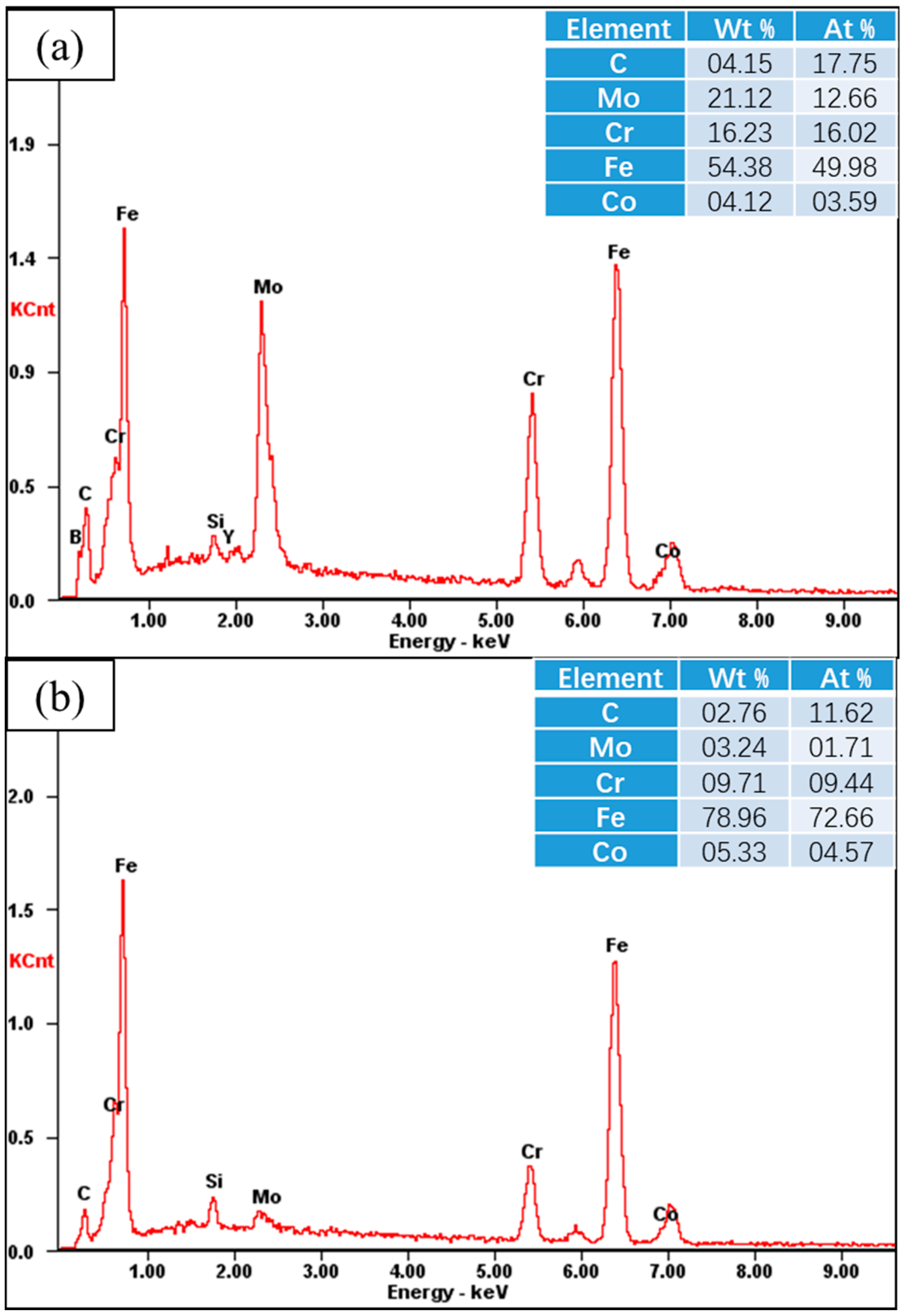
Figure 4c is magnification of area C of the coating-substrate binding zone in Figure 4a. The bottom is a columnar crystal zone grown from the substrate and has a thickness of about 20–30 μm, indicating that the cladding layer forms a good metallurgical bond with the substrate. Figure 4d is an enlarged view of the columnar crystal region of Figure 4c. There are strip-shaped precipitates between columnar grains. In order to analyze the compositional differences between the columnar grains and intergranular precipitates, EDS spot scanning tests were performed on points 1 and 2 in Figure 4d. The results are shown in Figure 5. The contents of Mo and Cr at point 1 are significantly higher than point 2, indicating that the precipitated phases are rich in Mo and Cr.
In order to analyze the compositional differences between different layers in the cladding, an EDS line scanning was carried out along a line crossing from the top surface of the cladding to the substrate, as shown in Figure 6. It can be clearly seen that the content of each element does not change significantly in the respective areas of the substrate and the cladding layer. But between the substrate and the cladding layer, the contents of Fe, Co, and Mo vary notably. In the narrow columnar region nearby, the bonding interface, the contents of elements, especially Fe and Mo, change significantly. From the substrate to the cladding layer, the Fe element content significantly reduced, and the Mo element content significantly increased. It is indicated that within the crystallized region, due to the melting of the substrate at the interface, the composition of the cladding layer was diluted by the substrate, and the elemental composition in this region deviated from the nominal composition of the amorphous alloy. In the laser cladding process, the key factors affecting the glass forming ability are the cooling rate and the composition of the cladding layer [22]. The dilution of the nominal composition near the bond zone will reduce the glass forming ability and favor the growth of the crystalline phase. In addition, the cooling rate at the bonding zone is lower than the upper layer [17], which is unfavorable to the formation of amorphous structure. From the interface upwards, the columnar grains gradually become smaller in size and finally disappear. The cladding layer becomes a featureless pattern that is difficult to etch. This is mainly because, on the one hand, the upper part of the cladding layer is less diluted by the substrate. EDS results showed that the element mass fraction of the region 2 of Figure 4a is the following: Fe: 45.35%, Cr: 13.81%, Mo: 22.44%, Co: 7.69%, C: 4.33%, and B: 4.64%, which is very close to the nominal composition of the Fe-based amorphous alloy powder, so the glass forming ability is high. On the other hand, as the distance from the substrate increases, the cooling rate increases, favoring the formation of the amorphous phase, thereby realizing the transition of the cladding layer structure from the columnar crystal to the amorphous region.
Figure 7 presents the microstructure of the multi-track laser cladding. Dark strip crystalline regions can be observed between the two adjacent tracks in Figure 7a. Figure 7b is a backscattered electron (BSE) micrograph of the strip crystalline regions area B in Figure 7a, which consists of a featureless region on the left and a crystallization zone on the right. Figure 7c shows the magnification of area C in Figure 7b. Considering the microstructure results of single-track laser cladding, it can be inferred that the reheating in multi-track laser cladding is the main reason that cause crystallization between adjacent tracks.
The XRD test results showed in Figure 2 were based on multi-track laser cladding, in which crystallization occurred between adjacent tracks and resulted in a higher amount of crystalline phases than the single track cladding.
3.2. Microhardness
Figure 8 shows the microhardness distribution curve in the thickness direction of the cladded specimen. The hardness shows a three-level step-down trend with the increase of the distance from the upper surface of the cladding layer. In the 0–600 μm thickness, the hardness is about 1100 , and is the highest in the cladding layer. The highest hardness in this region is 1179 , which is close to that of the bulk amorphous alloy tested (max 1200). In the heat-affected zone, the hardness decreases significantly to about 400 . The hardness of the substrate is the lowest of about 200 .
3.3. Wear Resistance
The wear tests results include the friction coefficient and wear volume loss is shown in Figure 9. When the wear processes reaches a steady state, the average coefficient of friction of the substrate is 0.29, which is 2.6 times that of the cladding layer (0.11, Figure 9a). The wear volume loss of the substrate is 1.65 , in comparison to 0.39 of the cladding layer (Figure 9b). Obviously, the cladding layer has a much better wear resistance than the substrate.
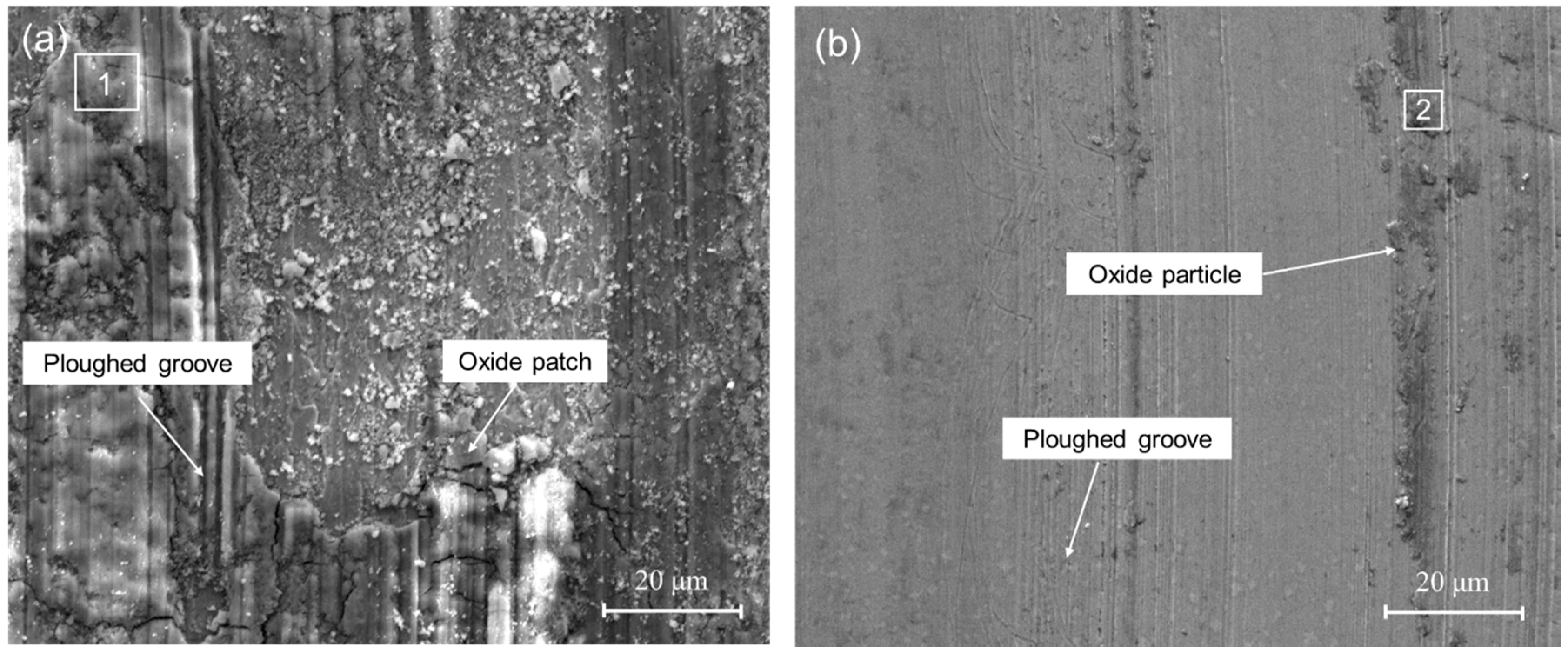
As presented by Figure 10a, the surface morphology of the worn substrate is featured by deep ploughed grooves with peeling of large oxide patches. There is obvious peeling and cracking on the surface, indicating that severe plastic deformation and destruction occurred on the surface during wear test. The EDS spectrum of the worn substrate (Figure 10c) shows that the surface layer mainly consists of Fe, Cr, Si, and O. The high oxygen content indicates that oxidative wear had occurred during the wear process. Simultaneously, the Si element had been transferred from the silicon nitride ball to the surface of the substrate, which indicates that the adhesive wear had occurred. Therefore, the main wear mechanism of the substrate is adhesive wear and oxidation wear. In contrast, as shown in Figure 10b, the surface morphology of the worn cladding layer is smooth, with only a small amount of slight ploughed grooves and little oxide particles. EDS test results (Figure 10c) show that the main elements of the surface particles are O, Mo, Cr, and Fe. The exfoliated oxide particles would act as abrasive particles and create ploughed grooves. Thus, the wear mechanism of the cladding layer is mainly abrasive wear with slight oxidation wear.
According to the abrasive wear theory proposed by E. Rabinowicz [23], abrasive wear volume loss , where K represents the variable concerning grinding materials, W represents the vertical loads, and is the hardness of the tested materials and L is the grinding distance. The abrasive wear volume loss is inversely proportional to the hardness of the material. Obviously, the high hardness of the amorphous phase improves the wear resistance of the cladding layer. In addition, due to the low plasticity of amorphous materials, it has stronger resistance to adhesive wear [24].
4. Conclusions
In this study, a novel Fe-based amorphous composite coating was successfully prepared on 3Cr13 stainless steel substrate by laser cladding of powders with a composition of (wt. %), based on which the following conclusions can be drawn:
- (1)
- The cladding layer is composed of a featureless amorphous phase in the upper part and a columnar crystal region at the bottom part. The crystalline phases include carbides , , and solid solution , and the volume fraction of the amorphous phase is calculated to be 52.8%. Significant elemental dilution occurs in the crystallization region, which resulted in the crystallization.
- (2)
- The highest hardness of the cladding layer is 1200 , which is about 6 times of that of the 3Cr13 stainless steel substrate (200 ).
- (3)
- The cladding layer have a much better wear resistance than the substrate: the friction coefficient of the laser cladding (0.11) is much lower than that of substrate (0.29), and the wear volume loss of the cladding layer is only about one fourth of that of the 3Cr13 substrate.
Author Contributions
X.H. performed all experiments and wrote the paper; B.C. and D.D. designed the experiments and reviewed the paper; K.W. performed the experiments; X.H. and Y.H. analyzed the data.
Funding
This research was funded by National Natural Science Foundation of China (Nos. 51675303 and 51605251); and the Tribology Science Fund of the State Key Laboratory of Tribology (SKLT2018B05). The APC was funded by the Tribology Science Fund of the State Key Laboratory of Tribology (SKLT2018B05).
Acknowledgments
The authors appreciate the financial support for this work from National Natural Science Foundation of China (Nos. 51675303 and 51605251); and the Tribology Science Fund of the State Key Laboratory of Tribology (SKLT2018B05).
Conflicts of Interest
The authors declare no conflict of interest.
References
- Ponnambalam, V.; Poon, S.J.; Shiflet, G.J. Fe-based bulk metallic glasses with diameter thickness larger than one centimeter. J. Mater. Res. 2004, 19, 1320–1323. [Google Scholar] [CrossRef]
- Schuh, C.A.; Hufnagel, T.C.; Ramamurty, U. Mechanical behavior of amorphous alloys. Acta Mater. 2007, 55, 4067–4109. [Google Scholar] [CrossRef]
- Hu, Y.; Pan, M.X.; Liu, L.; Zhao, Y.H.; Zhao, D.Q.; Wang, W.H. Synthesis of Fe-based bulk metallic glasses with low purity materials by multi-metalloids addition. Mater. Lett. 2003, 57, 2698–2701. [Google Scholar] [CrossRef]
- Cheney, J.; Vecchio, K. Development of quaternary Fe-based bulk metallic glasses. Mater. Sci. Eng. A 2008, 492, 230–235. [Google Scholar] [CrossRef]
- Zhou, Z.; Wang, L.; Wang, F.C.; Zhang, H.F.; Liu, Y.B.; Xu, S.H. Formation and corrosion behavior of Fe-based amorphous metallic coatings by HVOF thermal spraying. Surf. Coat. Technol. 2009, 204, 563–570. [Google Scholar] [CrossRef]
- Guo, R.Q.; Zhang, C.; Chen, Q.; Yang, Y.; Li, N.; Liu, L. Study of structure and corrosion resistance of Fe-based amorphous coatings prepared by HVAF and HVOF. Corros. Sci. 2011, 53, 2351–2356. [Google Scholar] [CrossRef]
- Kishitake, K.; Era, H.; Otsubo, F. Thermal-sprayed Fe-10CM3P-7C amorphous coatings possessing excellent corrosion resistance. J. Therm. Spray Technol. 1996, 5, 476–482. [Google Scholar] [CrossRef]
- Cadney, S.; Brochu, M. Formation of amorphous Zr41.2Ti13.8Ni10Cu12.5Be22.5 coatings via the ElectroSpark Deposition process. Intermetallics 2008, 16, 518–523. [Google Scholar] [CrossRef]
- Bergmann, H.W.; Mordike, B.L. Laser and electron-beam melted amorphous layers. J. Mater. Sci. 1981, 16, 863–869. [Google Scholar] [CrossRef]
- Yoshioka, H.; Asami, K.; Kawashima, A.; Hashimoto, K. Laser-processed corrosion-resistant amorphous Ni Cr P B surface alloys on a mild steel. Corros. Sci. 1987, 27, 981–995. [Google Scholar] [CrossRef]
- Sahasrabudhe, H.; Bandyopadhyay, A. Laser processing of Fe based bulk amorphous alloy coating on zirconium. Surf. Coat. Technol. 2010, 205, 2661–2667. [Google Scholar] [CrossRef]
- Katakam, S.; Hwang, J.Y.; Paital, S.; Banerjee, R.; Vora, H.; Dahotre, N.B. In Situ Laser Synthesis of Fe-Based Amorphous Matrix Composite Coating on Structural Steel. Metall. Mater. Trans. A 2012, 43, 4957–4966. [Google Scholar] [CrossRef]
- Zheng, B.; Zhou, Y.; Smugeresky, J.E.; Lavernia, E.J. Processing and Behavior of Fe-Based Metallic Glass Components via Laser-Engineered Net Shaping. Metall. Mater. Trans. A 2009, 40, 1235–1245. [Google Scholar] [CrossRef] [Green Version]
- Wang, K.; Chang, B.; Lei, Y.; Fu, H.; Lin, Y. Effect of Cobalt on Microstructure and Wear Resistance of Ni-Based Alloy Coating Fabricated by Laser Cladding. Metals 2017, 7, 551. [Google Scholar] [CrossRef]
- Majumdar, J.D.; Manna, I. Introduction to Laser Assisted Fabrication of Materials; Springer: Berlin/Heidelberg, Germany, 2013. [Google Scholar]
- Wang, Y.; Lu, Q.; Xiao, L.; Shi, Z. Laser Cladding Fe-Cr-Si-P Amorphous Coatings on 304L Stainless. Rare Met. Mater. Eng. 2014, 43, 274–277. [Google Scholar]
- Basu, A.; Samant, A.N.; Harimkar, S.P.; Majumdar, J.D.; Manna, I.; Dahotre, N.B. Laser surface coating of Fe-Cr-Mo-Y-B-C bulk metallic glass composition on AISI 4140 steel. Surf. Coat. Technol. 2008, 202, 2623–2631. [Google Scholar] [CrossRef]
- Wu, X.; Hong, Y. Fe-based thick amorphous-alloy coating by laser cladding. Surf. Coat. Technol. 2001, 141, 141–144. [Google Scholar] [CrossRef]
- Zhu, Q.; Qu, S.; Wang, X.; Zou, Z. Synthesis of Fe-based amorphous composite coatings with low purity materials by laser cladding. Appl. Surf. Sci. 2007, 253, 7060–7064. [Google Scholar] [CrossRef]
- Balla, V.K.; Bandyopadhyay, A. Laser processing of Fe-based bulk amorphous alloy. Surf. Coat. Technol. 2010, 205, 2661–2667. [Google Scholar] [CrossRef]
- Maurya, R.S.; Sahu, A.; Laha, T. Quantitative phase analysis in Al86Ni8Y6 bulk glassy alloy synthesized by consolidating mechanical alloyed amorphous powder via spark plasma sintering. Mater. Des. 2016, 93, 96–103. [Google Scholar] [CrossRef]
- Shu, F.Y.; Liu, S.; Zhao, H.Y.; He, W.X.; Sui, S.H.; Zhang, J.; He, P.; Xu, B.S. Structure and high-temperature property of amorphous composite coating synthesized by laser cladding FeCrCoNiSiB high-entropy alloy powder. J. Alloys Compd. 2018, 731, 662–666. [Google Scholar] [CrossRef]
- Rabinowicz, E.; Tanner, R.I. Friction and Wear of Materials. J. Appl. Mech. 1995, 33, 606–611. [Google Scholar] [CrossRef]
- Wen, S.; Huang, P. The Principle of Tribology; Tsinghua University Press: Beijing, China, 2008; pp. 458–460. [Google Scholar]
Figure 1.
SEM photograph of the powders.

Figure 2.
XRD patterns of the powders and the multi-track laser claddings, showing the (a) powders and (b) the cladding layers.
Figure 2.
XRD patterns of the powders and the multi-track laser claddings, showing the (a) powders and (b) the cladding layers.
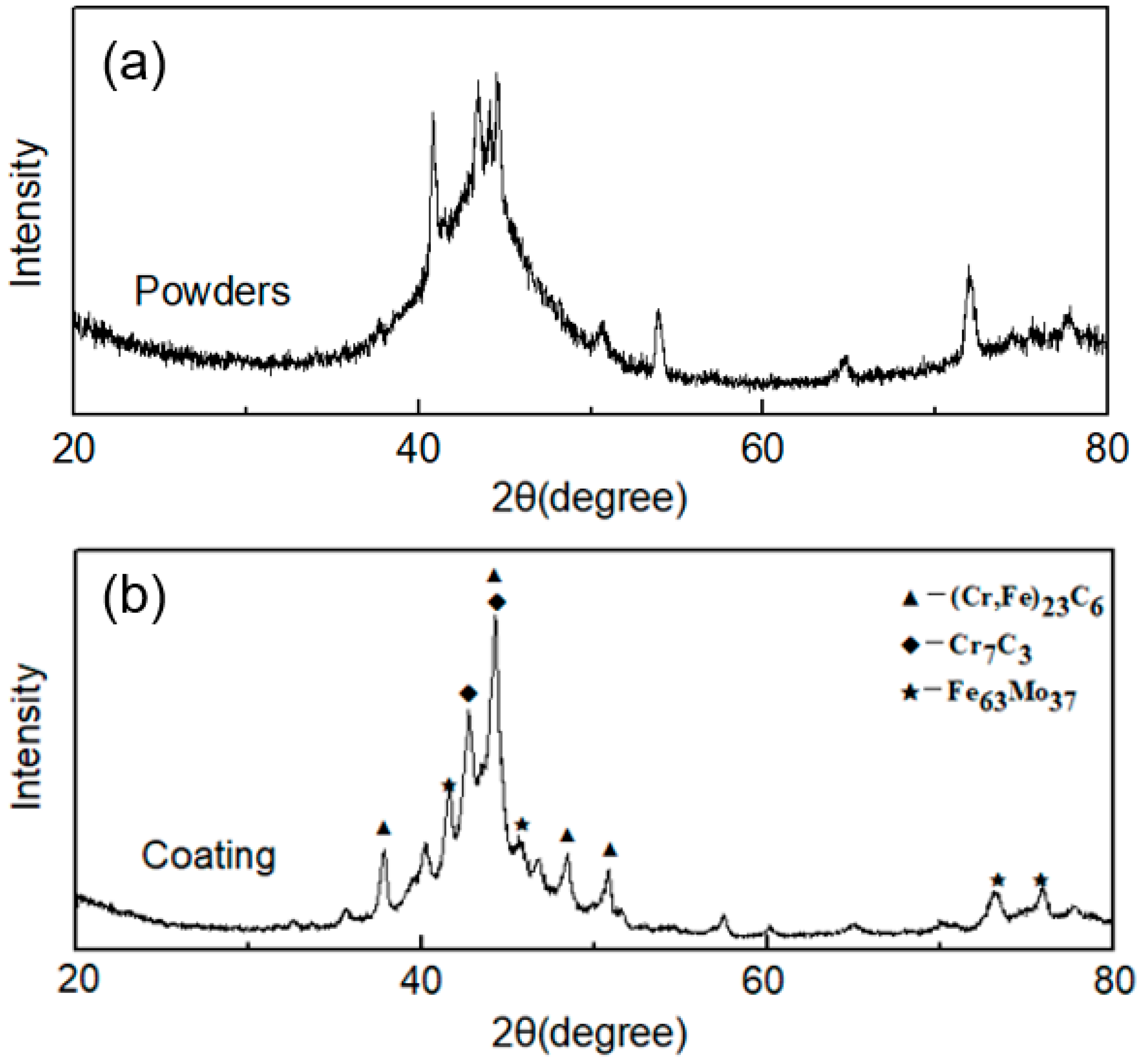
Figure 3.
The low-magnification scanning electron micrograph of the single-track laser cladding.

Figure 4.
The microstructures of the single-track laser cladding, showing the (a) overall view, (b) magnification of area B in (a), (c) magnification of area C in (a), and (d) the magnification of area D in (c).
Figure 4.
The microstructures of the single-track laser cladding, showing the (a) overall view, (b) magnification of area B in (a), (c) magnification of area C in (a), and (d) the magnification of area D in (c).


Figure 6.
EDS line scan position and test results showing (a) the scanning position and (b) element distribution along line 1.
Figure 6.
EDS line scan position and test results showing (a) the scanning position and (b) element distribution along line 1.
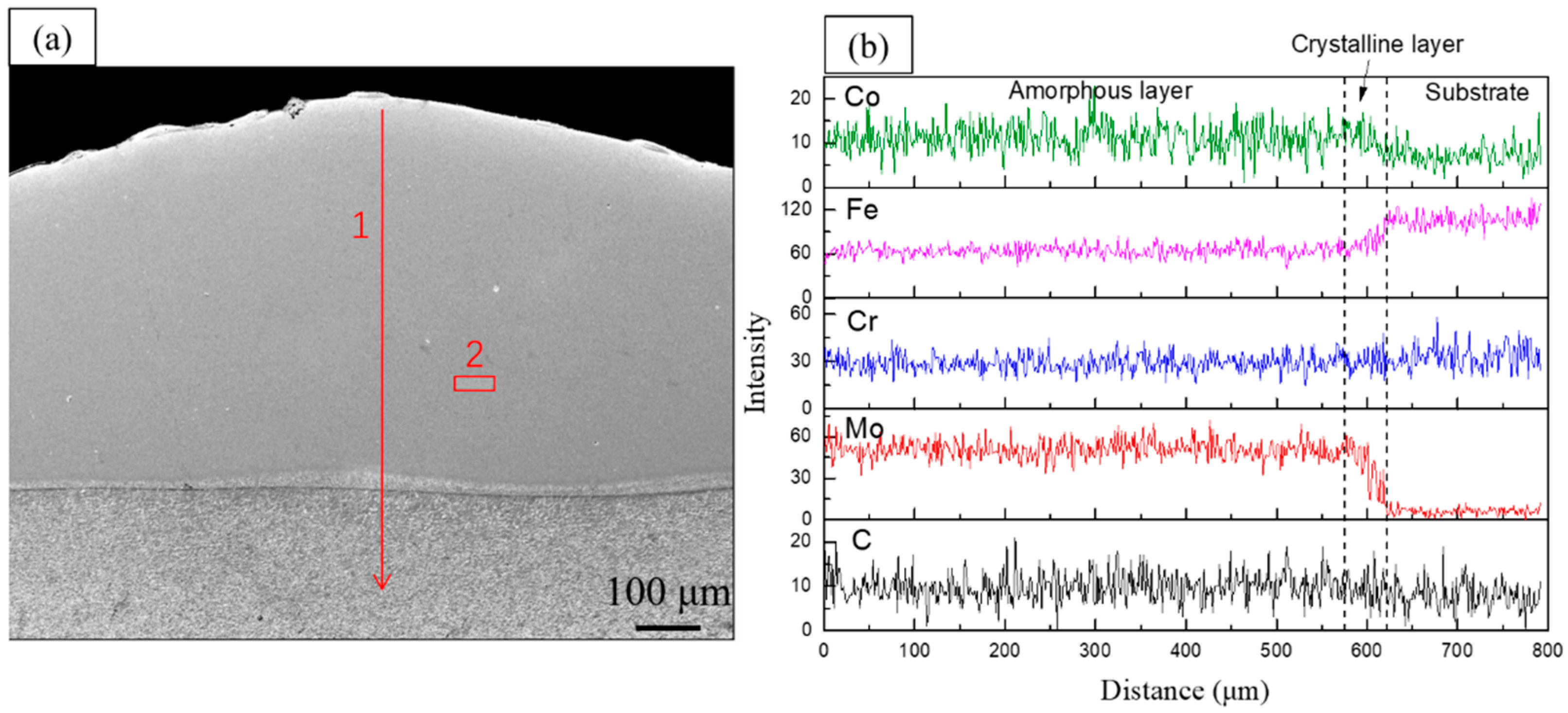
Figure 7.
The microstructures of the multi-track laser cladding with (a) an overall view, (b) a BSE micrograph of area B in (a), and (c) a BSE micrograph of area C in (b).
Figure 7.
The microstructures of the multi-track laser cladding with (a) an overall view, (b) a BSE micrograph of area B in (a), and (c) a BSE micrograph of area C in (b).
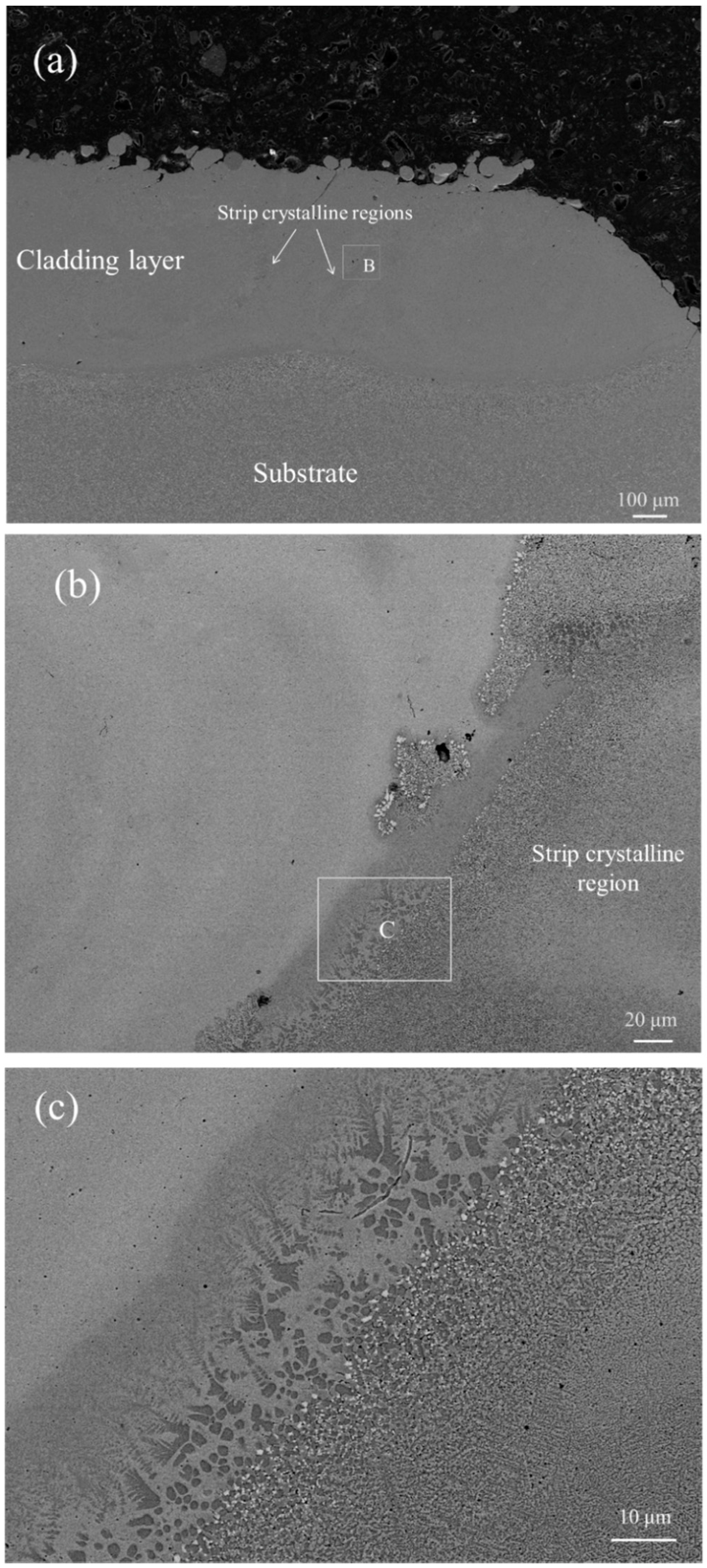
Figure 8.
Variation of microhardness along the thickness of the cladding specimen.
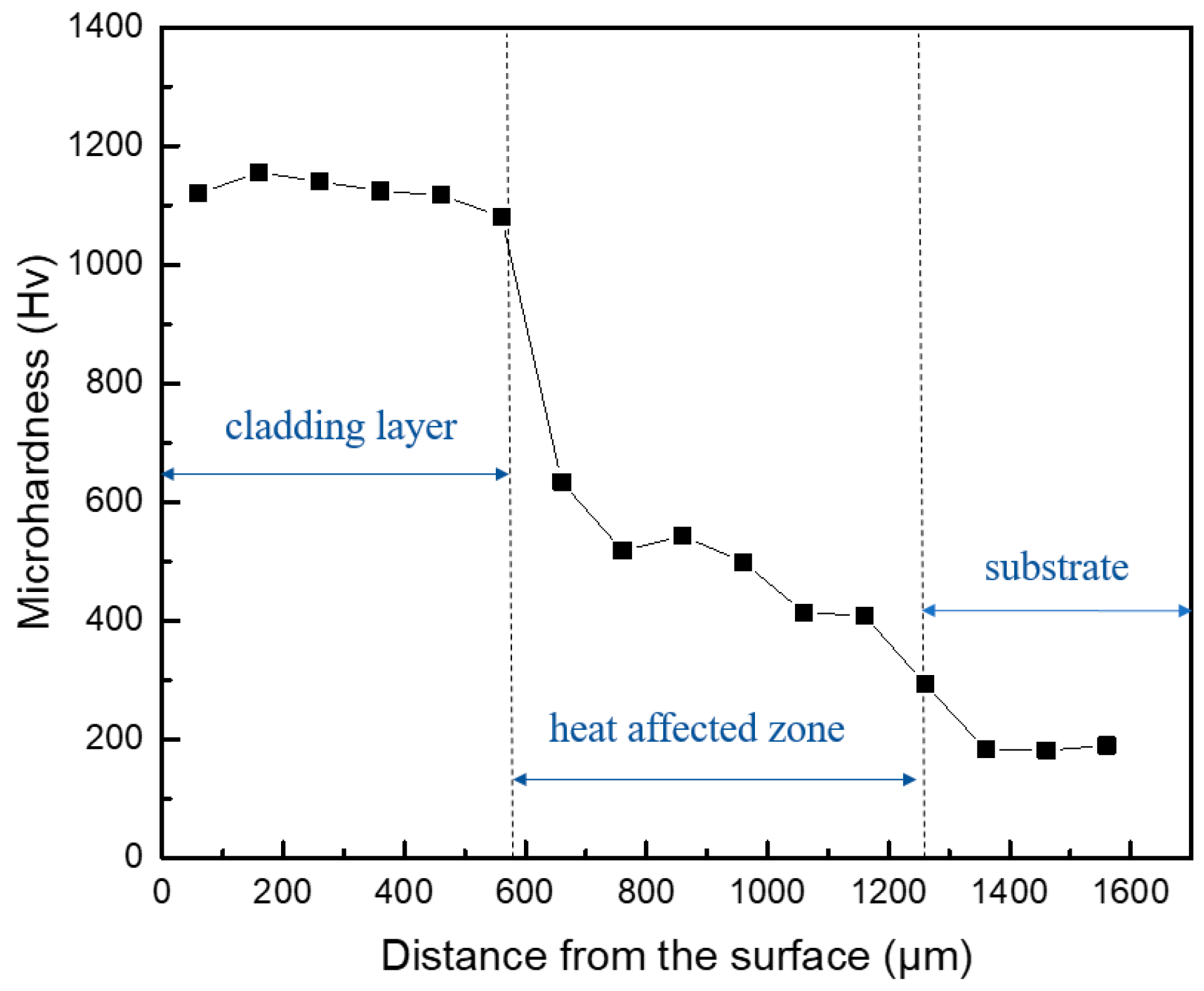
Figure 9.
Test results of the wear behavior, (a) coefficient of friction of the substrate and the cladding layer, (b) wear volume loss of the substrate and the cladding layer.
Figure 9.
Test results of the wear behavior, (a) coefficient of friction of the substrate and the cladding layer, (b) wear volume loss of the substrate and the cladding layer.

Figure 10.
The worn surfaces of the (a) substrate and (b) the cladding layer, EDS results of (c) zone 1 and (d) zone 2.
Figure 10.
The worn surfaces of the (a) substrate and (b) the cladding layer, EDS results of (c) zone 1 and (d) zone 2.


Table 1.
Chemical composition of the 3Cr13 stainless steel substrate (wt. %).
| Element | C | Cr | Ni | Si | Mn | P | S | Fe |
|---|---|---|---|---|---|---|---|---|
| wt. % | 0.26~0.35 | 12.00~14.00 | ≤0.60 | ≤1.00 | ≤1.00 | ≤0.035 | ≤0.03 | Bal. |
Table 2.
Experimental parameters of the laser cladding.
| Laser Power (W) | Scanning Speed (mm/min) | Powder Feeding Rate (g/min) | Overlapping Rate (%) |
|---|---|---|---|
| 500 | 600 | 10 | 30 |
© 2018 by the authors. Licensee MDPI, Basel, Switzerland. This article is an open access article distributed under the terms and conditions of the Creative Commons Attribution (CC BY) license (http://creativecommons.org/licenses/by/4.0/).
Share and Cite
MDPI and ACS Style
Hou, X.; Du, D.; Wang, K.; Hong, Y.; Chang, B. Microstructure and Wear Resistance of Fe-Cr-Mo-Co-C-B Amorphous Composite Coatings Synthesized by Laser Cladding. Metals 2018, 8, 622. https://doi.org/10.3390/met8080622
AMA Style
Hou X, Du D, Wang K, Hong Y, Chang B. Microstructure and Wear Resistance of Fe-Cr-Mo-Co-C-B Amorphous Composite Coatings Synthesized by Laser Cladding. Metals. 2018; 8(8):622. https://doi.org/10.3390/met8080622
Chicago/Turabian StyleHou, Xiangchun, Dong Du, Kaiming Wang, Yuxiang Hong, and Baohua Chang. 2018. "Microstructure and Wear Resistance of Fe-Cr-Mo-Co-C-B Amorphous Composite Coatings Synthesized by Laser Cladding" Metals 8, no. 8: 622. https://doi.org/10.3390/met8080622
Note that from the first issue of 2016, this journal uses article numbers instead of page numbers. See further details here.