Effect of Martensite–Austenite Constituent on Low-Temperature Toughness in YS 500 MPa Grade Steel Welds


1
Department of Material Science and Engineering, Pusan National University, Busan 46241, Korea
2
Technical Research Center, Hyundai steel Company, Chungnam 31719, Korea
3
Material Development team, Samhaw Steel Company, Busan 47018, Korea
4
Dongnam Regional Division, Korea Institute of Industrial Technology, Busan 46742, Korea
5
Department of Advanced Material Engineering, Dong-eui University, Busan 47227, Korea
*
Author to whom correspondence should be addressed.
Metals 2018, 8(8), 638; https://doi.org/10.3390/met8080638
Submission received: 2 July 2018
/
Revised: 3 August 2018
/
Accepted: 8 August 2018
/
Published: 14 August 2018
Abstract
:The effect of martensite–austenite (M–A) constituents and simulated microstructure on low-temperature toughness was investigated in YS 500 MPa grade structural steel welds. The specimens were fabricated using a direct quenching and tempering process. After simulated weld thermal cycles, the coarse-grained heat-affected zone (CGHAZ) and intercritically reheated coarse-grained heat-affected zone (IRCGHAZ) were produced using a Gleeble tester and real welded joint to support the simulation results. The largest low-temperature toughness was observed in the fine-grained heat-affected zone (FGHAZ) owing to the fine-ferrite microstructure. However, the toughness decreased in the IRCGHAZ because of the slender morphology of the M–A constituents that formed primarily along the prior austenite grain boundaries in the IRCGHAZ.
1. Introduction
Recently, more offshore plants and ships have been operated in extreme environments such as those commonly found in the polar regions [1]. Low carbon bainitic steels are candidate materials used for their combination of high strength and low-temperature toughness by applying thermomechanically controlled processes (TMCPs) [2,3,4]. Although the base metal (BM) has excellent toughness, deterioration of the toughness in welded joints occurs for large heat input welds. The deterioration of the fracture toughness of TMCP steels after welding is attributed to the formation of local brittle zones in the heat affected zones (HAZs) [5]. For single pass welding, the coarse-grained heat-affected zone (CGHAZ) exhibits the lowest toughness and forms near the fusion line [6]. For multi-pass welding, the most degraded part in the HAZ is known as the intercritically reheated coarse-grained heat-affected zone (ICCGHAZ) [7,8] and is caused by the formation of coarse M–A constituents, which are composed of high carbon martensite and retained austenite [9]. It is generally recognized that cleavage fracturing in welded joints is mainly controlled by the microstructure, such as the M–A constituents. The micro-mechanism of cleavage cracks in simulated HAZs is controlled by the size and volume fraction of the martensite–austenite (M–A) constituent [10,11]. Furthermore, it should be noted that the morphologies of M–A constituents are sensitive to cleavage cracking [12,13]. The M–A constituents can exhibit various morphologies such as massive, slender, and small dot shapes [14,15]. Specifically, the M–A constituents with small dot as well as dispersed and distributed shapes to not significantly contribute to the decrease in toughness [16]. A previous study reported that the slender M–A constituents crack more easily than massive M–A constituents in YS 480 MPa grade steel welds [17]. However, the micro-mechanism of cleavage cracking and the effects of M–A constituents were not systematically studied for high strength steel welds. Therefore, this study aimed to investigate the effect of volume fraction, location, and morphology of M–A constituents on the low-temperature toughness of the simulated HAZs and real multi-pass welds in YS 500 MPa grade steel welds.
2. Experimental Details
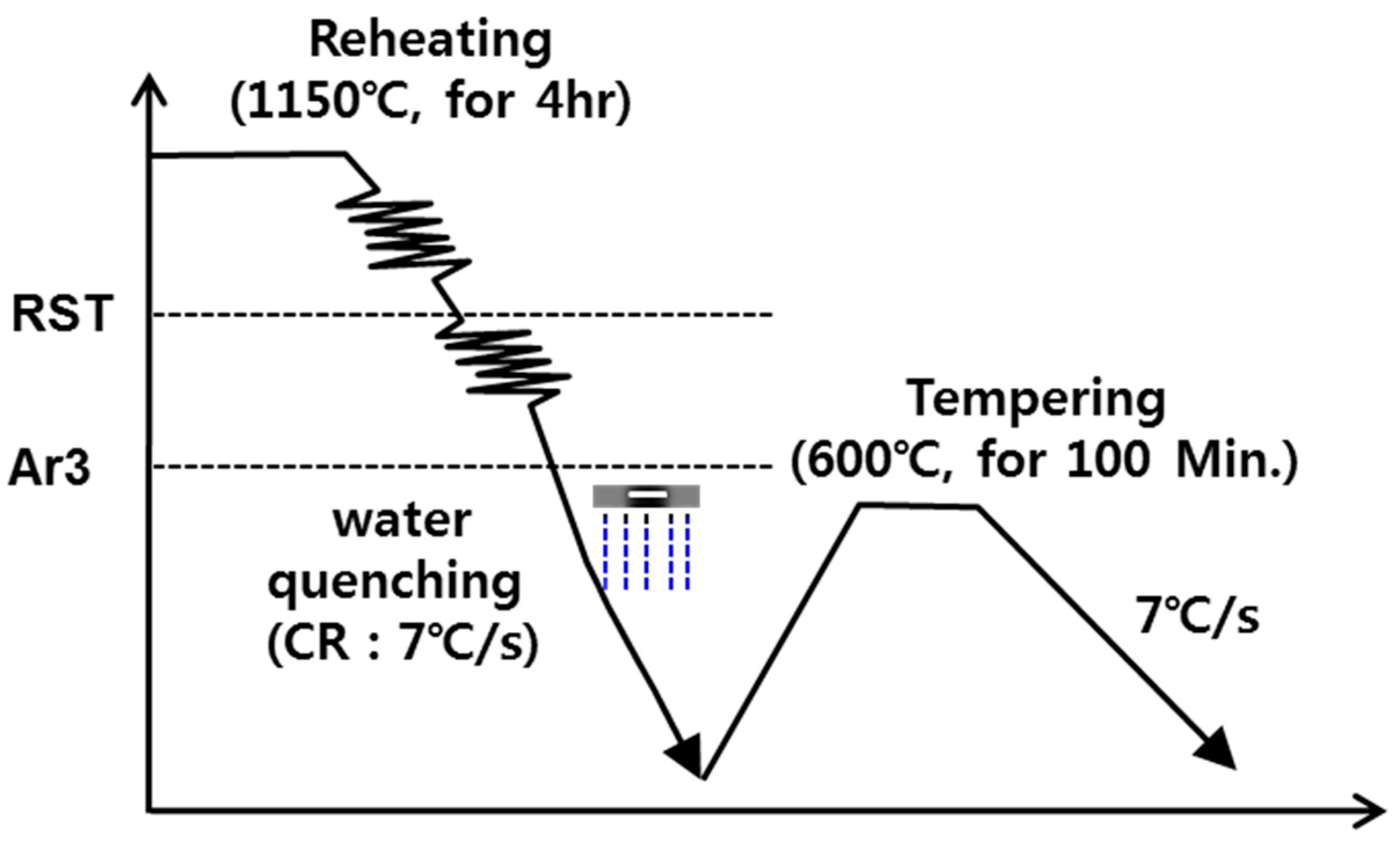
The BM used in this study was S500G2 plates of YS 500 grade [18] and the BM to ensure good weldability was designed with a relatively low carbon equivalent (Ceq). The chemical composition of the BM is listed in Table 1. The fabrication process of the BM is shown in Figure 1. A solidified slab was reheated and homogenized at 1150 °C for 4 h, and hot rolling was started at 950 °C and ceased above Ar3. During rolling, the slab thickness was reduced from 250 to 62 mm, followed by water quenching. After accelerated cooling, tempering was performed at 600 °C for 100 min to increase the toughness of the BM.
To simplify the real welding conditions and ensure an accurate region of each HAZ, HAZ simulation was conducted using a Gleeble 3500 tester (Gleeble, New York, NY, USA). The thermal cycles were designed to simulate a submerged arc weld with heat input of 5 kJ/mm to a 62 mm thick plate. The specimens were cut from 1/4 t of the fabricated steel plate of 11 mm (thickness) × 11 mm (width) × 90 mm (length). The thermal cycles used in this study are shown in Figure 2. Test specimens were heated to a peak temperature of 1350 °C (TP1) at a rate of 500 °C/s and were held at this temperature for 3 s. Thereafter, the specimens were cooled to 200 °C and the cooling time (t8/5) between 800 and 500 °C was 31 s in accordance with the Rosenthal equation [19]. Subsequent cycles were conducted at peak temperatures (TP2) of 900, 750, and 600 °C to simulate FGHAZ, IRCGHAZ, and subcritically reheated CGHAZ (SRCGHAZ), respectively. The other conditions were held constant including TP1, holding time, and cooling rate (t8/5).
The real weld joint was produced on the BM with a size of 62 mm (thickness) × 500 mm (width) × 1000 mm (length), which was cut along the longitudinal direction. A single V-type butt weld with a groove angle of 30° was performed with twenty-six-passes to produce a relatively wide HAZ region. The filler metal wire had a diameter of 4.0 Φ and fluxes (S-500Y) for the submerged arc welding (SAW). The composition of the filler metal was listed in Table 1. The detailed welding conditions of the SAW process are listed in Table 2.
The thermal cycle of the Gleeble test was applied to rectangular specimens taken from the BM of 11 mmT × 11 mmW × 55 mmL. Thereafter, the specimens were machined to produce Charpy V-notched (CVN) standard specimens of 10 mmT × 10 mmW × 55 mmL [20]. For the welds, CVN impact specimens with a standard size were prepared along the transverse direction of the welding passes. Notches in the impact specimens were made near the fusion line. Impact testing was performed at −40 °C, in triplicate to obtain the average value of CVN. The phase of each regional HAZ was observed using X-ray diffraction (XRD) (Bruker, Dresden, German). at a scan time of 0.5 s, range of 30–130°, voltage of 40 kV, and current of 30 mA using Co Kα radiation. The metallographic specimens were cut from the centerline of the HAZ simulated specimen. For microstructural analysis, the specimens were polished and etched using a 3% Nital solution. Their microstructure was then observed using light optical microscopy (LOM) and scanning electron microscopy (SEM). In the real welded joint, the fraction of various HAZs and WM from the notch line was averaged from the LOM images of 5 ea (×200) following Recommended Practice for Preproduction Qualification for steel plates (API RP 2Z) [21]. To identify the morphology and amount of M–A constituents in the various HAZs, the specimens were re-polished and etched using the LePera reagent (1% Na2S2O5 solution and 4% picric acid, alcohol solution). The segregation of composition of the M–A constituent was performed using field emission-electron probe microanalysis (FE-EPMA) and the fracture surface morphology of the impact specimens was examined using SEM.
3. Results and Discussion
3.1. Microstructure and Mechanical Properties of the Base Metal
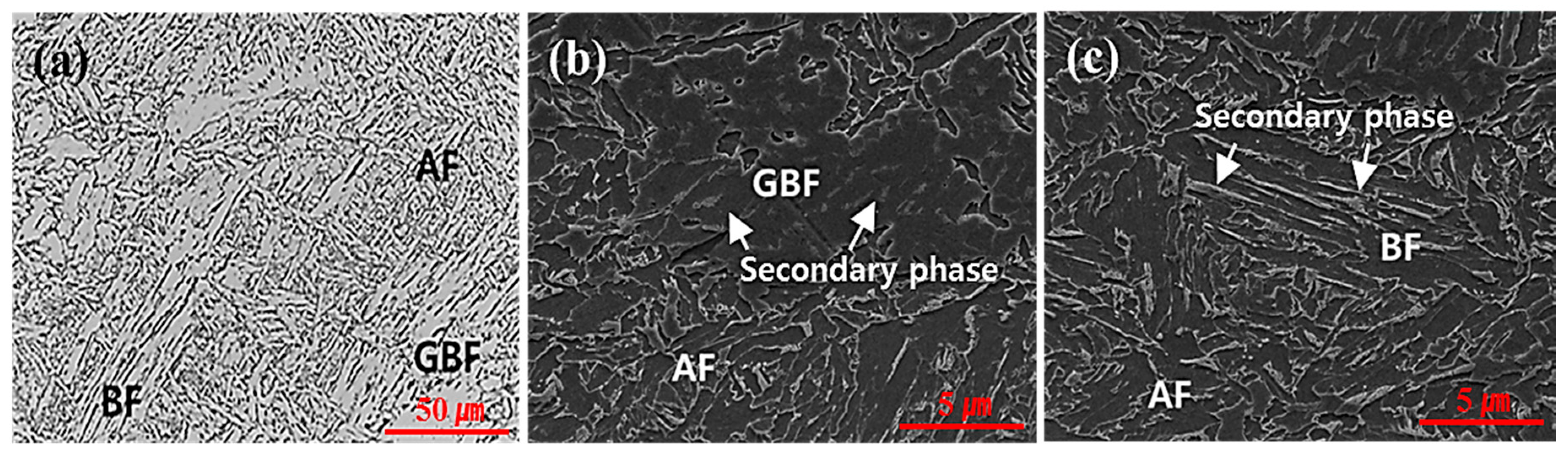
Figure 3 shows various microstructures of the BM. The microstructure of the BM was composed of a mixed structure of acicular ferrite (AF), granular bainitic ferrite (GBF), and bainitic ferrite (BF). The major constituent was AF, and the combined fraction of GBF/BF was present in small amounts (~20%). AF had fine ferrite lath approximately 3 ± 1 μm in size and formed irregularly, with no secondary phase inside the AF. BF showed a microstructure where the laths were well developed and the prior austenite grain boundary (PAGB) was observed. Furthermore, BF had relatively coarse grains of packet 50 ± 5 μm in size as compared with AF. The secondary phase was distributed along the block boundary of the bainitic structure (Figure 3c). GBF existed in the secondary phase of the island type in the interior of the grains, and its grains were coarse and 30 ± 5 μm in size. Detailed characterization of the secondary phase will be explained in Section 3.2.1. It was previously reported that a microstructural fraction of GBF and BF below 25% produced excellent balance between impact toughness and mechanical properties [22]. The yield strength, ultimate tensile strength, and elongation were approximately 550 MPa, 640 MPa, and 26%, respectively. The CVN energy at −40 °C was 284 J and the ductile-brittle transition occurred at −80 °C. These values satisfy the EN 10025 and NORSOK M–120 standards [23,24].
3.2. Microstructure and Mechanical Properties of Simulated HAZ
3.2.1. Microstructural Behaviour for Various HAZs
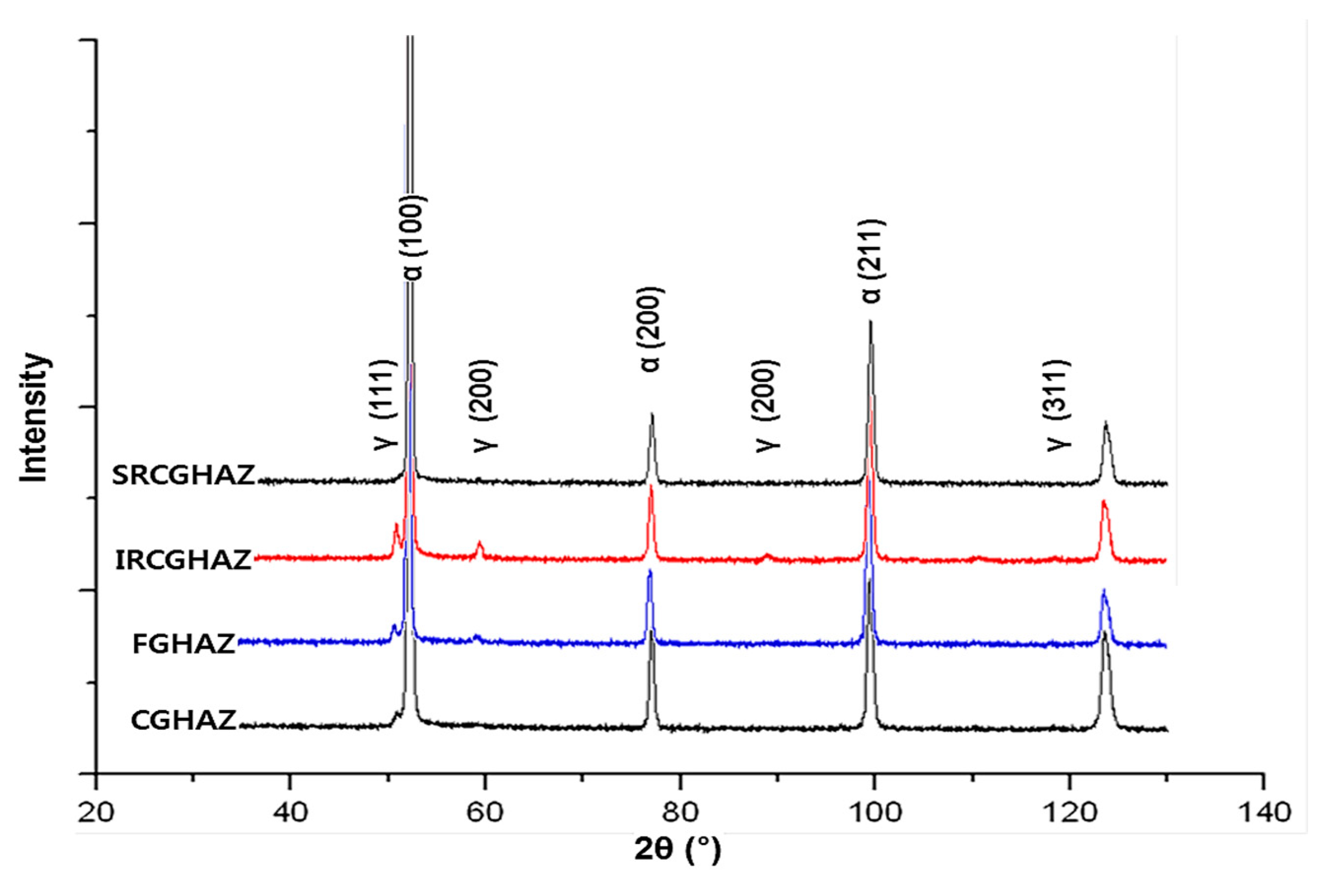
Figure 4 shows the LOM microstructures of the simulated HAZs. CGHAZ had only one pass (TP1 1350 °C) and consisted of AF, BF, and a small fraction of GBF (Figure 4a). The secondary phase of the M–A constituent existed in the GBF grain of CGHAZ. The microstructure of the fine-grained heat-affected zone (FGHAZ) was influenced by the subsequent passes (TP1 1350 °C + TP2 900 °C) and was transformed into fine polygonal ferrite (<15 µm) and AF (Figure 4b). This was mainly due to the complete recrystallization at a relatively low peak temperature (TP2 900 °C). Figure 4c shows the microstructure of IRCGHAZ composed of AF and BF owing to the effect of subsequent passes (TP1 1350 °C + TP2 750 °C). The microstructure (AF, BF, and GBF) of SRCGHAZ was similar to that of CGHAZ (Figure 4d) except for its small grain size. Figure 5 shows the XRD patterns of each HAZ region, indicating that the SRCGHAZ was composed of the α-ferrite phase, and CGHAZ started to show a γ-austenite phase peak. FGHAZ/IRCGHAZ clearly showed two phases (α-ferrite + γ-austenite).
Figure 6 shows the microstructures of each simulated HAZ using the LePera reagent. Figure 6a,b show the distributions and morphology of the M–A constituents, respectively. LOM images of the microstructures indicate that the M–A constituents appear as the white phase. For CGHAZ, a small amount (~0.9%) of lath-shaped M–A constituent was observed on the PAGB and inside the BF microstructure [26]. The volume fractions of the M–A constituent in FGHAZ and IRCGHAZ were similar and greater than 2%. However, the shapes of their M–A constituents differed significantly. Unlike FGHAZ with a well-developed massive-shaped M–A constituent, both massive- and slender-shaped constituents coexisted in the IRCGHAZ. The location of the M–A constituents in these microstructures also differed for each simulated HAZ. For FGHAZ, the M–A constituents were randomly observed in the inter-ferrite grain. On the other hand, the M–A constituents in the IRCGHAZ were concentrated primarily along the PAGB [27,28]. For SRCGHAZ, the M–A constituent was hardly observed, and coarsened cementite was detected in the BF microstructure. Various HAZs showed consistent trends of M–A content measured by the LePera reagent (Figure 6), as compared with the XRD results (Figure 5).
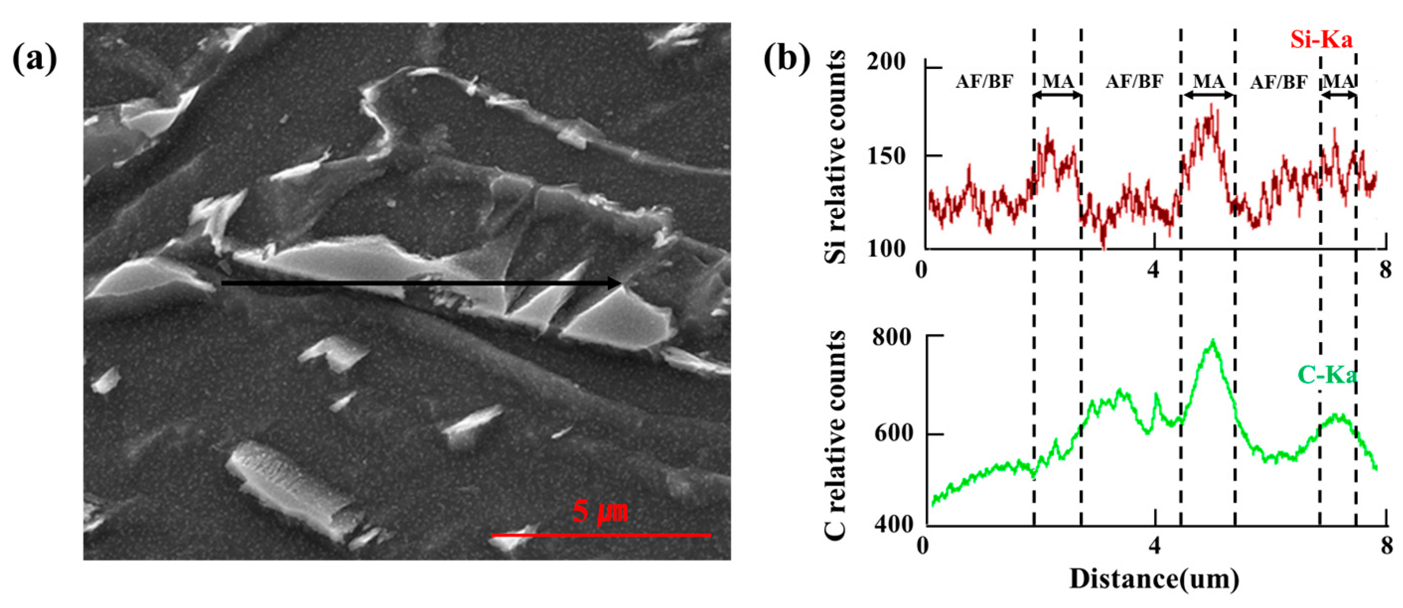
The M–A constituents were observed using XRD pattern analysis (Figure 5) and LOM with the LePera reagent (Figure 6). To verify the presence of the M–A constituents, Figure 7a shows the massive M–A constituent in the lath BF matrix of the IRCGHAZ, and Figure 7b indicates the corresponding carbon/silicon concentration distributions determined by FE-EPMA along the black-scanning line. The carbon and silicon were concentrated in the M–A constituent in the IRCGHAZ. The carbon of the massive M–A constituent was significantly concentrated compared to the matrix. However, the segregation degree of silicon on the massive M–A constituent was insignificant compared to the carbon segregation due to the lower diffusion coefficient of silicon compared to carbon [29]. Carbon significantly improves the stability of the retained austenite and lowers the martensite start temperature (Ms) in these regions. The silicon in the steel is known to delay the decomposition of retained austenite and increase the amount of M–A constituent [30]. Therefore, carbon and silicon segregation in the study encouraged the formation of the M–A constituent.
3.2.2. Mechanical Properties of the Various HAZs
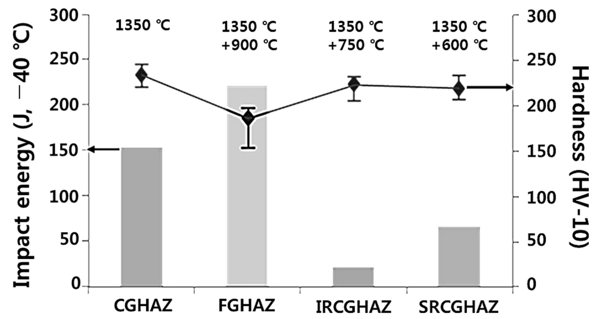
Figure 8 shows the CVN-absorbed energy and hardness distribution for each simulated HAZ. The impact-absorbed energies at −40 °C were 150 J for CGHAZ, 220 J for FGHAZ, 25 J for IRCGHAZ, and 70 J for SRCGHAZ. The CGHAZ mainly consisted of AF, which has excellent impact toughness and a slight amount of brittle BF. The M–A constituent content was low for the CGHAZ, resulting in the large CVN value. The FGHAZ had a decreased fraction of brittle BF and increased fraction of ferrite (quasi-ferrite and AF) with excellent impact toughness [31,32]. Therefore, its CVN energy increased dramatically and Vickers hardness decreased by more than 20 Hv with an increasing ferrite fraction despite the FGHAZ having a large fraction of massive M–A. The IRCGHAZ mainly consisted of AF and BF, contributing its high hardness value of 220 Hv similar to that of the CGHAZ. However, the slender shaped M–A constituent was observed at the PAGB, and some of the M–A constituent was also observed in the lath of BF. Therefore, the average CVN energy of the IRCGHAZ was quite small (~25 J). The microstructure (AF and BF) and hardness distribution of the SRCGHAZ was similar to that of the CGHAZ. However, the CVN-absorbed energy in these regions was quite low (~70 J) because of the coarse cementite in the BF microstructure. The shape and amount of M–A constituent were determined to the main reasons for the decrease in the CVN-absorbed energy.
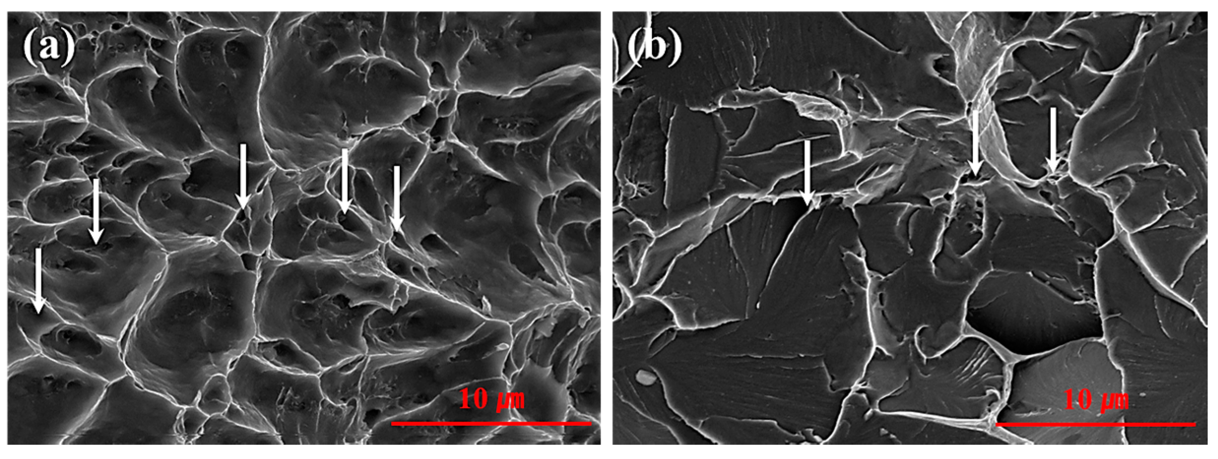
Figure 9 shows the Charpy-fractured surface of the FGHAZ and IRCGHAZ. The fracture mode of FGHAZ was composed of mixed dimples and cleavage fractures (Figure 9a). The M–A constituent particles, indicated by the white arrows, were uniformly distributed in the grain and grain boundary of the FGHAZ. The IRCGHAZ fracture mode was principally composed of cleavage fractures (Figure 9b). Large M–A constituent particles were observed close to the grain boundary of the IRCGHAZ. Specifically, the cleavage surface was initiated near the M–A constituent along the grain boundary. The amount of cleavage surface in the FGHAZ was significantly smaller than that of the IRCGHAZ. The minimum crack initiation energy of the IRCGHAZ specimens can be attributed to the slender shaped M–A constituents and those located at the grain-boundary [29].
3.3. Properties of a Real Welded Joint Formed Using the Fabricated Steel Plate
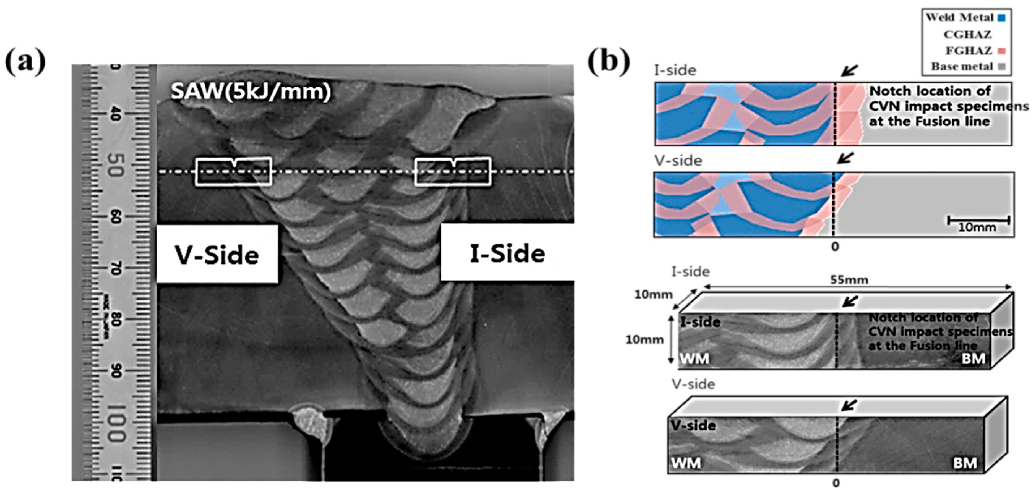
In real welding processes, superheated microstructures close to the fusion line are generated by the significant heat input and shape of the stacked groove. In addition, various HAZ microstructures (CGHAZ, FGHAZ, IRCGHAZ, and SRCGHAZ) coexist, which are determined by the stacking shapes of the deposited bead. Submerged arc welding was performed to evaluate the CVN impact value of a SMYS 500-MPa-class steel plate. The macrostructure of the welded joint is shown in Figure 10a. The I-side and V-side of the welded groove was applied to produce various HAZ microstructures as a function of the beveled groove shape. I-Side produced the notch by penetrating the CGHAZ of the weld beads, and V-Side produced the notch so that the areas of WM and HAZ were equivalent. To observe each fraction of the HAZ microstructure according to the groove shape (I- and V-side) at the fusion line, the specimens were cut 10 mm below the surface (Figure 10b). The V-side of the welded groove showed the following fraction of each microstructure: 30% BM, 20% WM, 8% IRCGHAZ, and 42% FGHAZ. The I-side of the welded groove was observed to have the following fraction of each microstructure: 20% welded metal, 2% IRCGHAZ, and 78% FGHAZ.
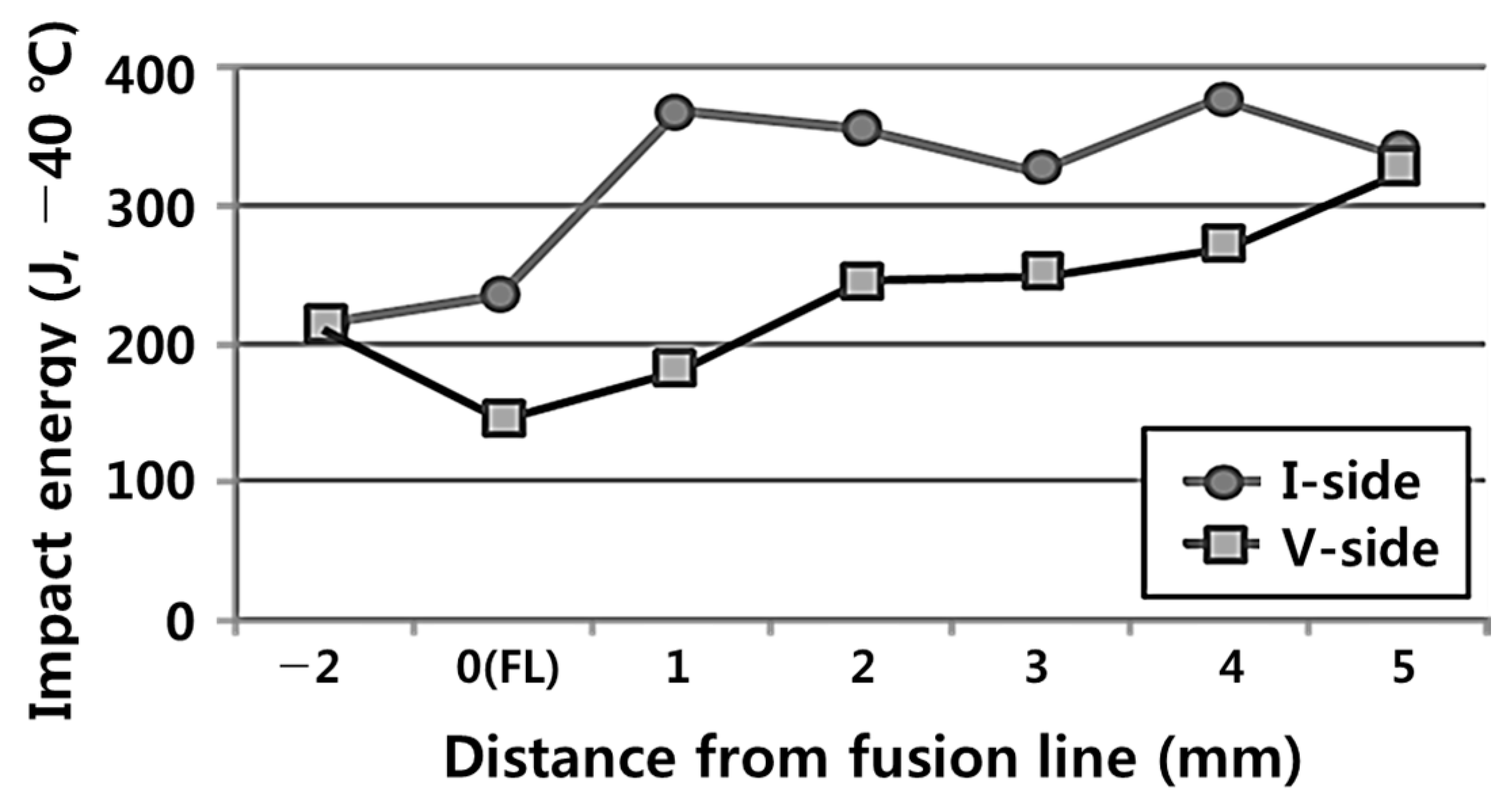
Figure 11 shows the CVN impact-absorbed energy for each notch location of the welded HAZ near the fusion line tested at −40 °C. The overall CVN-absorbed energy near the I-side of the welded groove was relatively higher than that near the V-side. Furthermore, the CVN-absorbed energy increased with increasing distance from the fusion line. For the location of the fusion line (FL) −2 mm and FL +5 mm, both the V- and I-sides of the welded groove showed equal values of CVN-absorbed energy. This result highlights our confidence in the V- and I-side experiments, as the notch location was hardly affected by thermal cycles. Therefore, the I-side of the welded groove had superior low-temperature toughness to that of the V-side. The inferior low-temperature toughness of the V-side HAZ region was strongly dependent on the fraction of the IRCGHAZ, which was determined to have slender M–A located primarily along the PAGB (Figure 6). The superior toughness of the I-side HAZ region was related to the large fraction of the FGHAZ, which was determined to consists of a large amount of fine ferrite and massive M–A randomly distributed in the inter-ferrite grain.
4. Conclusions
The microstructural and mechanical properties of SMYS 500 MPa-grade steel welds were investigated by HAZ simulation and analysis of a real welded joint. The main conclusions of this study can be summarized as follows:
- (1)
- The Gleeble simulator produced various HAZs including CGHAZ, FGHAZ, IRCGHAZ, and SRCGHAZ in the real welded joint. IRCGHAZ contained AF and BF microstructures, and FGHAZ contained mostly fine polygonal ferrite and AF. The microstructure of CGHAZ mainly consisted of AF, BF, and a small fraction of GBF. SRCGHAZ had the same type of microstructure as CGHAZ except for the small grain size. Therefore, various HAZs produced mostly same type of microstructure, i.e., AF, BF, and GBF.
- (2)
- The volume fractions of the M–A constituents in FGHAZ and IRCGHAZ were similar and greater than 2%. Unlike FGHAZ with massive-shaped M–A constituents that were randomly distributed in the inter-ferrite grain, both massive- and slender-shaped constituents coexisted in the IRCGHAZ primarily along the PAGB. The M–A constituent was hardly observed in SRCGHAZ. The CGHAZ contained a small amount (~0.9%) of lath-shaped M–A constituent on the PAGB and inside the BF microstructure.
- (3)
- The morphology and distribution of the M–A influenced the low-temperature impact toughness of the simulated HAZs. The FGHAZ exhibited superior toughness and showed mixed dimples and cleavage fractures due to the randomly distributed massive M–A in the inter-ferrite grain. However, the IRCGHAZ exhibited inferior toughness and typical cleavage fractures because its slender M–A located primarily along the PAGB. As a result, the low-temperature impact toughness was deteriorated as the volume fraction of M–A constituents increased and the distribution of the slender-shaped M–A constituents concentrated in the PAGB.
- (4)
- During the real submerged arc welding process, the I-side groove produced a smaller amount of the IRCGHAZ than that of the V-side groove. Therefore, the I-side of the welded groove was superior to the V-side in terms of CVN-absorbed energy tested at –40 °C. The design of multi-pass weld joints with less IRCGHAZ is recommended and can be achieved by applying optimized groove design to improve the toughness of the welds for the structure used in extreme environments.
Author Contributions
I.K., Y.P. and N.K. conceived and designed the experiments; I.K. and H.N. performed the experiments; I.K., M.L., and D.N. analyzed and discussed the data; I.K., H.N and N.K. wrote the paper.
Funding
This study was supported by GCRC-SOP (Grant No. 2011-0030013) of the National Research Foundation of Korea funded by the Korean government (MSIT), and the National Research Foundation of Korea (NRF) funded by the Ministry of Education (Grant No. NRF-2016R1D1A1B03933994).
Conflicts of Interest
The authors declare no conflict of interest.
References
- Kim, J.H.; Choi, S.W.; Park, D.H.; Lee, J.M. Charpy impact properties of stainless steel weldment in liquefied natural gas pipelines: Effect of low temperatures. Mater. Des. 2015, 65, 914–922. [Google Scholar] [CrossRef]
- Misra, R.D.K.; Nathani, H.; Hartmann, J.E.; Siciliano, F. Microstructural evolution in a new 770 MPa hot rolled Nb-Ti microalloyed steel. Mater. Sci. Eng. A 2005, 394, 339–352. [Google Scholar] [CrossRef]
- Nishioka, K.; Ichikawa, K. Progress in thermomechanical control of steel plates and their commercialization. Sci. Technol. Adv. Mater. 2012, 13, 023001. [Google Scholar] [CrossRef] [PubMed] [Green Version]
- Park, C.; Kang, N.; Liu, S. Effect of grain size on the resistance to hydrogen embrittlement of API 2W Grade 60 steels using in situ slow-strain-rate testing. Corros. Sci. 2017, 128, 33–41. [Google Scholar] [CrossRef]
- Amer, A.E.; Koo, M.Y.; Lee, K.H.; Kim, S.H.; Hong, S.H. Effect of welding heat input on microstructure and mechanical properties of simulated HAZ in Cu containing microalloyed steel. J. Mater. Sci. 2010, 45, 1248–1254. [Google Scholar] [CrossRef]
- Moon, J.; Kim, S.J.; Lee, C. Effect of thermo-mechanical cycling on the microstructure and strength of lath martensite in the weld CGHAZ of HSLA steel. Mater. Sci. Eng. A 2011, 528, 7658–7662. [Google Scholar] [CrossRef]
- Li, X.; Fan, Y.; Ma, X.; Subramanian, S.V.; Shang, C. Influence of Martensite-Austenite constituents formed at different intercritical temperatures on toughness. Mater. Des. 2015, 67, 457–463. [Google Scholar] [CrossRef]
- You, Y.; Shang, C.; Chen, L.; Subramanian, S. Investigation on the crystallography of the transformation products of reverted austenite in intercritically reheated coarse grained heat affected zone. Mater. Des. 2013, 43, 485–491. [Google Scholar] [CrossRef]
- Haugen, V.G.; Rogne, B.R.S.; Akselsen, O.M.; Thaulow, C.; Østby, E. Local mechanical properties of intercritically reheated coarse grained heat affected zone in low alloy steel. Mater. Des. 2014, 59, 135–140. [Google Scholar] [CrossRef]
- Chen, J.H.; Kikuta, Y.; Araki, T.; Yoneda, M.; Matsuda, Y. Micro-fracture behaviour induced by M–A constituent (Island Martensite) in simulated welding heat affected zone of HT80 high strength low alloyed steel. Acta. Metall. 1984, 32, 1779–1788. [Google Scholar] [CrossRef]
- Bonnevie, E.; Ferrière, G.; Ikhlef, A.; Kaplan, D.; Orain, J.M. Morphological aspects of martensite-austenite constituents in intercritical and coarse grain heat affected zones of structural steels. Mater. Sci. Eng. A 2004, 385, 352–358. [Google Scholar] [CrossRef]
- Lambert-Perlade, A.; Gourgues, A.F.; Besson, J.; Sturel, T.; Pineau, A. Mechanisms and modelling of cleavage fractures in simulated heat affected zone microstructures in HSLA steel. Metall. Mater. Trans. A 2004, 35, 1039–1053. [Google Scholar] [CrossRef]
- Davis, C.L.; King, J.E. Cleavage initiation in the intercritically reheated coarse-grained heat-affected zone: Part I. Fractographic evidence. Metall. Mater. Trans. A 1994, 25, 563–573. [Google Scholar] [CrossRef]
- Lan, L.; Qiu, C.; Zhao, D.; Gao, X.; Du, L. Analysis of microstructural variation and mechanical behaviors in submerged arc welded joint of high strength low carbon bainitic steel. Mater. Sci. Eng. A 2012, 558, 592–601. [Google Scholar] [CrossRef]
- Qiu, C.; Lan, L.; Zhao, D.; Gao, X.; Du, L. Microstructural evolution and toughness in the HAZ of submerged arc welded low welding crack susceptibility steel. Acta. Metall. Sin. 2013, 26, 49–55. [Google Scholar] [CrossRef]
- Lan, H.F.; Du, L.X.; Misra, R.D.K. Effect of microstructural constituents on strength-toughness combination in a low carbon bainitic steel. Mater. Sci. Eng. A 2014, 611, 194–200. [Google Scholar] [CrossRef]
- Di, X.J.; An, X.; Cheng, F.J.; Wang, D.P.; Guo, X.J.; Xue, Z.K. Effect of martensite–austenite constituent on toughness of simulated inter-critically reheated coarse-grained heat-affected zone in X70 pipeline steel. Sci. Technol. Weld. Join. 2016, 21, 366–373. [Google Scholar] [CrossRef]
- Standard Specification for Weldable Structural Steels for Fixed Offshore Structures-Technical Delivery Conditions. BS EN 10225. 2009. Available online: https://www.din.de/en/getting-involved/standards-committees/fes/wdc-beuth: din21:119761806 (accessed on 5 December 2017).
- Information Technology-Calculating Program, Japan Welding Engineering Society Standards. Available online: http://www-it.jwes.or.jp (accessed on 5 December 2017).
- Standard Specification for Notched Bar Impact Testing of Metallic Materials1; ASTM E23-07: 2007; American Society for Testing and Materials (ASTM): West Conshohocken, PA, USA, 2007; Available online: http://mhriau.ac.ir/_DouranPortal/Documents/ASTM%20E23%20%28impact%20test%29_20160406_233024.pdf (accessed on 5 December 2017).
- Recommended Practice for Preproduction Qualification for Steel Plates for Offshore Structures, Fourth Edition Standard; American Petroleum Institute (API): Washington, DC, USA, 2005; Available online: http://starglobal.com.vn/upload/files/Standard/206015667-API-RP-2Z-4th-Ed.pdf (accessed on 5 December 2017).
- Kim, I.; Lee, M.; Choi, Y.; Kang, N. Effects of Mo content on low-angle misorientation microstructure and mechanical properties of YS 550 MPa-Grade steels for offshore structures. Steel Res. Int. 2018, 89, 1700278. [Google Scholar] [CrossRef]
- South African Standard for Structural Steel, SANS 50025: 2009/EN 10025: 2004; SABS Standards Division: Cape Town, South Africa, 2004; Available online: https://store.sabs.co.za/pdfpreview.php?hash=5f3dfdb0e5ecf68792de91b64be6363c551259d8&preview=yes (accessed on 5 December 2017).
- Material Data Sheets for Structural Steel, NORSOK STANDARD M–120: 2000. Available online: http://www.standard.no/pagefiles/1170/m-120.pdf (accessed on 5 December 2017).
- Meester, B.D. The Weldability of Modern Structural TMCP Steels. ISIJ Int. 1997, 37, 537–551. [Google Scholar] [CrossRef]
- Terasaki, H.; Komizo, Y.I. Correlation between the microstructural development of bainitic ferrite and the characteristics of martensite-austenite constituent. Metall. Mater. Trans. A 2013, 44, 5289–5293. [Google Scholar] [CrossRef]
- Lee, S.; Kim, B.C.; Kwon, D. Fracture toughness analysis of heat-affected zones in high-strength low-alloy steel welds. Metall. Mater. Trans. A 1993, 24, 1133–1141. [Google Scholar] [CrossRef]
- Hu, J.; Du, L.X.; Wang, J.J.; Xie, H.; Gao, H.C.R.; Misra, R.D.K. High toughness in the intercritically reheated coarse-grained (ICRCG) heat-affected zone (HAZ) of low carbon microalloyed steel. Mater. Sci. Eng. A 2014, 590, 323–328. [Google Scholar] [CrossRef]
- Lan, L.; Qiu, C.; Zhao, D.; Gao, X.; Du, L. Analysis of martensite-austenite constituent and its effect on toughness in submerged arc welded joint of low carbon bainitic steel. J. Mater. Sci. 2012, 47, 4732–4742. [Google Scholar] [CrossRef]
- Taillard, R.; Verrier, P.; Maurickx, T.; Foct, J. Effect of silicon on CGHAZ toughness and microstructure of microalloyed steels. Metall. Mater. Trans. A 1995, 26, 447–457. [Google Scholar] [CrossRef]
- Han, C.; Li, K.; Liu, X.; Cao, R.; Cai, Z. Effect of Ti content and martensite-austenite constituents on microstructure and mechanical property. Sci. Technol. Weld. Join. 2018, 23, 410–419. [Google Scholar] [CrossRef]
- Lee, M.; Kang, N.; Liu, S.; Cho, K. Effects of inclusion size and acicular ferrite on cold cracking for high-strength steel welds of YS 600 MPa grade. Sci. Technol. Weld. Join. 2016, 21, 711–719. [Google Scholar] [CrossRef]
Figure 1.
Schematic illustration to produce the base metal.

Figure 2.
Schematic diagram of the simulated thermal cycles.
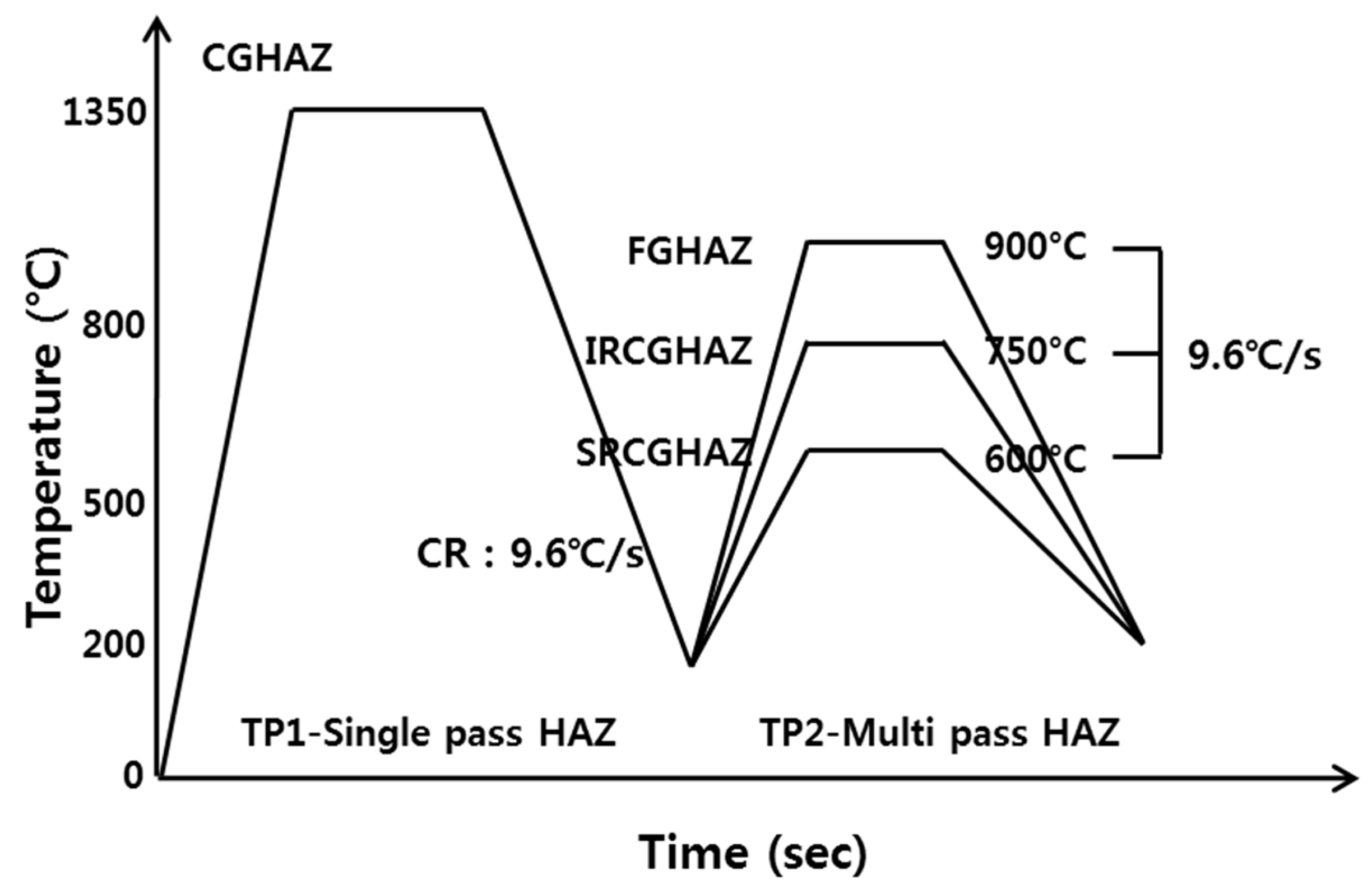
Figure 3.
Various microstructures of the base metal: (a) LOM image of BM; and (b), (c) SEM images of AF, BF, and GBF.
Figure 3.
Various microstructures of the base metal: (a) LOM image of BM; and (b), (c) SEM images of AF, BF, and GBF.

Figure 4.
LOM microstructure of each simulated HAZ: (a) CGHAZ; (b) FGHAZ; (c) IRCGHAZ; and (d) SRCGHAZ [25].
Figure 4.
LOM microstructure of each simulated HAZ: (a) CGHAZ; (b) FGHAZ; (c) IRCGHAZ; and (d) SRCGHAZ [25].

Figure 5.
XRD patterns of each simulated HAZ.

Figure 6.
Microstructures of each simulated HAZs: (a) CGHAZ; (b) FGHAZ; (c) IRCGHAZ; and (d) SRCGHAZ.
Figure 6.
Microstructures of each simulated HAZs: (a) CGHAZ; (b) FGHAZ; (c) IRCGHAZ; and (d) SRCGHAZ.

Figure 7.
Microstructures and EPAM analysis of IRCGHAZ: (a) the shape of M–A constituent; and (b) line analysis of element segregated on the M–A constituent.
Figure 7.
Microstructures and EPAM analysis of IRCGHAZ: (a) the shape of M–A constituent; and (b) line analysis of element segregated on the M–A constituent.

Figure 8.
Charpy-absorbed energy and hardness distribution for each simulated HAZ.

Figure 9.
The fracture surface morphology of the specimens with different weld positions: (a) FGHAZ; and (b) IRCGHAZ.
Figure 9.
The fracture surface morphology of the specimens with different weld positions: (a) FGHAZ; and (b) IRCGHAZ.

Figure 10.
Macrostructure and notch location of the real welded joint: (a) macrostructure of a real welded joint; (b) notch location of the CVN impact specimen at the fusion line according to the groove shape (I- and V-sides).
Figure 10.
Macrostructure and notch location of the real welded joint: (a) macrostructure of a real welded joint; (b) notch location of the CVN impact specimen at the fusion line according to the groove shape (I- and V-sides).

Figure 11.
CVN-absorbed energy as a function of notch location.


Table 1.
Chemical composition of the base metal and filler metal.
| C | Si | Mn | Ni | Cr | Cu | Mo | Ti | Nb | Ceq | |
|---|---|---|---|---|---|---|---|---|---|---|
| Base metal | 0.07 | 0.15 | 1.55 | 0.6 | - | 0.25 | 0.15 | 0.012 | 0.02 | 0.41 |
| Filler metal | 0.08 | 0.25 | 1.55 | 0.8 | 0.03 | 0.09 | 0.46 | - | - | - |
Table 2.
Welding conditions to produce the welded joint [18].
Table 2.
Welding conditions to produce the welded joint [18].
| Main Parameter | Current (A) | Voltage (V) | Travel Speed (cm/min) | Heat Input (kJ/cm) | InterpassTemperature (°C) |
|---|---|---|---|---|---|
| Range | 680–720 | 32–36 | 25–30 | 46–55 | ≤250 |
© 2018 by the authors. Licensee MDPI, Basel, Switzerland. This article is an open access article distributed under the terms and conditions of the Creative Commons Attribution (CC BY) license (http://creativecommons.org/licenses/by/4.0/).
Share and Cite
MDPI and ACS Style
Kim, I.; Nam, H.; Lee, M.; Nam, D.; Park, Y.; Kang, N. Effect of Martensite–Austenite Constituent on Low-Temperature Toughness in YS 500 MPa Grade Steel Welds. Metals 2018, 8, 638. https://doi.org/10.3390/met8080638
AMA Style
Kim I, Nam H, Lee M, Nam D, Park Y, Kang N. Effect of Martensite–Austenite Constituent on Low-Temperature Toughness in YS 500 MPa Grade Steel Welds. Metals. 2018; 8(8):638. https://doi.org/10.3390/met8080638
Chicago/Turabian StyleKim, In, Hyunbin Nam, Myungjin Lee, Daegeun Nam, Yeongdo Park, and Namhyun Kang. 2018. "Effect of Martensite–Austenite Constituent on Low-Temperature Toughness in YS 500 MPa Grade Steel Welds" Metals 8, no. 8: 638. https://doi.org/10.3390/met8080638
Note that from the first issue of 2016, this journal uses article numbers instead of page numbers. See further details here.