Fatigue-Prone Details in Steel Bridges


Civil and Environmental Engineering Department, Division of Structural Engineering, Chalmers University of Technology, Sven Hultins Gata 8, 41296 Gothenburg, Sweden
*
Author to whom correspondence should be addressed.
Buildings 2012, 2(4), 456-476; https://doi.org/10.3390/buildings2040456
Submission received: 31 August 2012
/
Revised: 1 November 2012
/
Accepted: 2 November 2012
/
Published: 12 November 2012
(This article belongs to the Special Issue Building Failures)
Abstract
:This paper reviews the results of a comprehensive investigation including more than 100 fatigue damage cases, reported for steel and composite bridges. The damage cases are categorized according to types of detail. The mechanisms behind fatigue damage in each category are identified and studied. It was found that more than 90% of all reported damage cases are of deformation-induced type and generated by some kind of unintentional or otherwise overlooked interaction between different load-carrying members or systems in the bridge. Poor detailing, with unstiffened gaps and abrupt changes in stiffness at the connections between different members were also found to contribute to fatigue cracking in many details.
1. Introduction
Bridges are vital parts of infrastructure in any modern society. In Europe, as in many other parts of the industrial world, the rapid industrial development that took place during the first half of the 19th century was accompanied by a huge expansion of the infrastructure including bridges in terms of quantity. Today, many of railway and highway bridges built in that period are still in use, despite the fact that their technical life span is—in many cases—deemed to be already completed. A recent mapping of the age profile of existing steel railway bridges in Europe [1] shows that more than 70% of these bridges are more than 50 years old and about 30% of them are more than 100 years old. Furthermore, this aged stock of railway and highway bridges is currently being subjected to more rigorous demands in terms of increased traffic intensity and higher traffic loads in order to meet the requirements for more efficient transportation systems.
Focusing on steel bridges, fatigue is often a major problem limiting the load-carrying capacity and the residual life of existing structures. The correct identification of fatigue-prone details in a bridge, along with well-planned inspection routines and successful strengthening and repair schedules, can guarantee the continuous and satisfactory performance of bridges during their service life. Also in new construction, it is important that structural details which have been shown to be susceptible with reference to fatigue to be avoided during design phase. As a result, information about the fatigue performance of various bridge details in existing bridges is vital for bridge managers or owners but also as feedback for bridge designers and engineers.
In an investigation reported on fatigue performance of existing steel and composite bridges [2], fatigue damage cases which had been reported for various bridge types and details were collected. A total of more than 100 damage cases were studied and categorized according to the type of detail and/or the mechanism behind the observed fatigue cracking. The results of this study show that more than 90% of all reported cases are of the kind caused by secondary effects, so-called deformation-induced cracking. This type of fatigue damage is often the result of secondary restraining forces generated by some kind of unintentional or overlooked interaction between different members in the bridge. Poor detailing, along with unstiffened gaps and abrupt changes in stiffness at the connections between different members, also contributes to fatigue cracking in most details. Design codes and evaluation methods generally provide very little guidance on how this kind of fatigue damage should be accounted for or prevented. It is the responsibility of the bridge designer to ensure—through good detailing—that these secondary effects and the kind of fatigue damage associated with them are avoided.
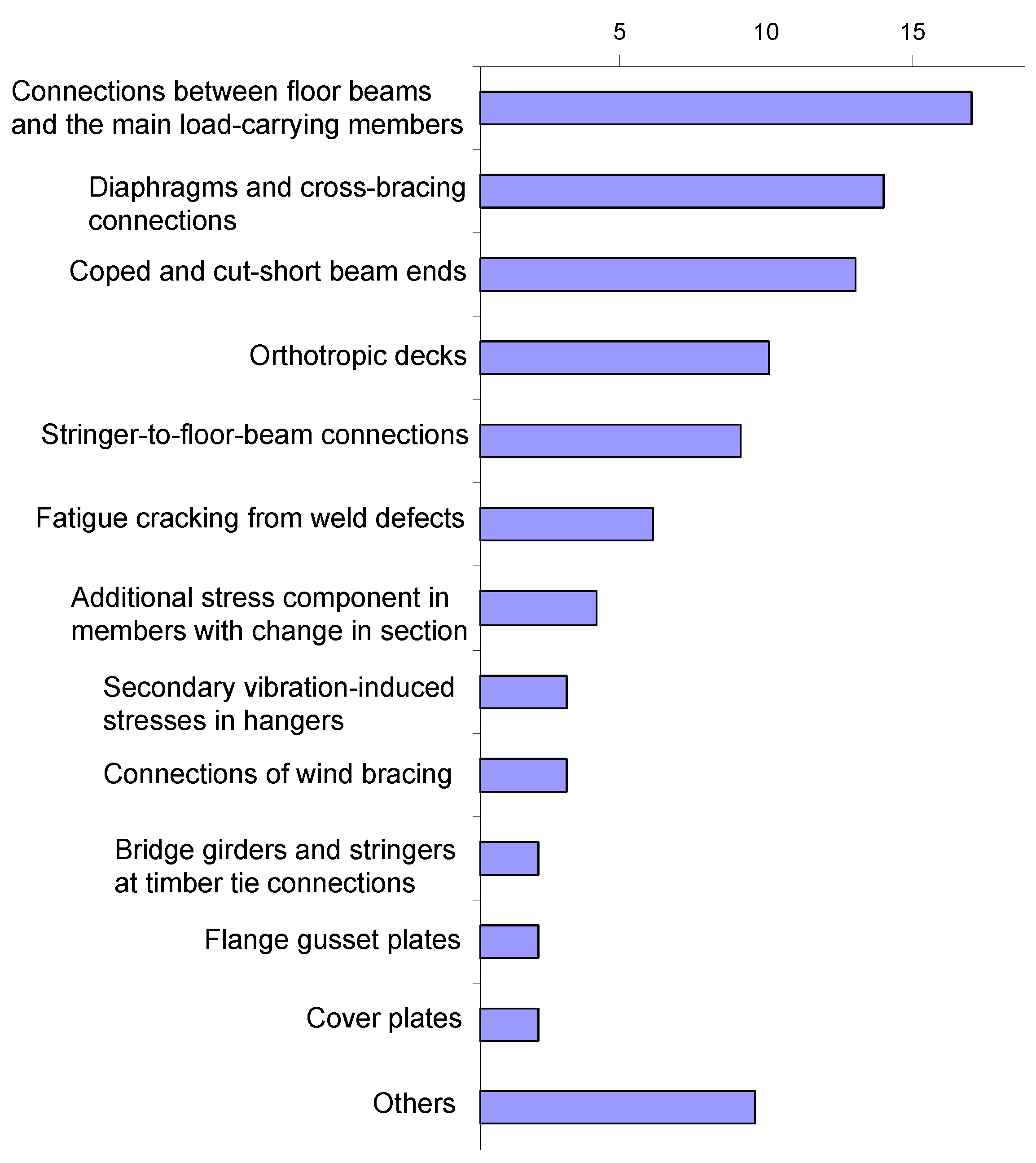
Figure 1 shows the collected damage cases categorized according to detail type. The most common types of deformation-induced fatigue damage can be found in the connections between stringers and floor beams, between the latter and the main load-carrying elements in the bridge and at the connections of diaphragms and cross-bracings. Moreover, fatigue damage in details in orthotropic decks and in bridge elements with coped ends or cut-short flanges at their connections to other elements are fairly common. In this paper, a number of common bridge details which have been shown to be susceptible to fatigue damage are reviewed. The mechanisms behind fatigue cracking in each detail type are discussed and issues related to poor detailing and overlooked or unforeseen behavior and load effects are addressed.
Figure 1.
Collected fatigue damage cases listed according to the type of detail in which they were encountered.
Figure 1.
Collected fatigue damage cases listed according to the type of detail in which they were encountered.

2. Fatigue Cracking from Weld Defects
In general, welded details are more susceptible to fatigue cracking in comparison to bolted or riveted ones. Weld defects and discontinuities such as weld undercut, entrapped porosities and lack of fusion are stress raisers from which fatigue cracking may initiate. Unfavorable welding residual stresses and stress concentrations due to weld geometry and welding induced micro-cracks are other factors that often accelerate the process of fatigue damage in welded bridge details.
In very few cases, weld defects have caused fatigue damage in steel bridge details, under the action of primary load effects. These cases are found either in fairly old bridges, built before quality control methods and non-destructive testing techniques were well developed, or in details which were regarded as “secondary” for the load-carrying capacity of the bridge and therefore were not included in quality control of this kind. One example of the latter case is the fatigue cracking in bridge girders with welded longitudinal stiffeners. Several bridges in the United States have experienced this type of cracking [3,4]. The cracks started from weld defects at the intersection between the fillet welds connecting the longitudinal stiffeners to the girder web and the butt welds made for transverse splices in the longitudinal stiffeners, see Figure 2. The detail was considered to be of secondary importance and no inspection of the weld intersection was made. The weld intersection also provided a path for the crack to grow from the stiffener into the girder web, resulting in brittle failure in some cases.
Figure 2.
Fatigue cracking in a bridge girder starting from weld defects at a weld intersection point (after [3]).
Figure 2.
Fatigue cracking in a bridge girder starting from weld defects at a weld intersection point (after [3]).

3. Details with Change in Section
Details which entail a change in the cross-section of an element or parts of an element are fairly common in steel bridges. The simplest example can be found in plate girders at transitions of flange dimensions (width, thickness or both). In an elementary detail of this kind, it is well recognized that the fatigue strength of the detail (a transverse butt weld in this case) can be substantially increased by creating a smooth transition between the connected plates. This can be achieved by either tapering or rounding the connected plate.
There are, however, more complex details in which a change in the cross-section of the element gives rise to a complex state of stress comprising additional stress components which could be high enough to cause fatigue damage in the detail. These stress components are usually somewhat difficult to predict by simple analysis and are sometimes neglected or overlooked by designers.
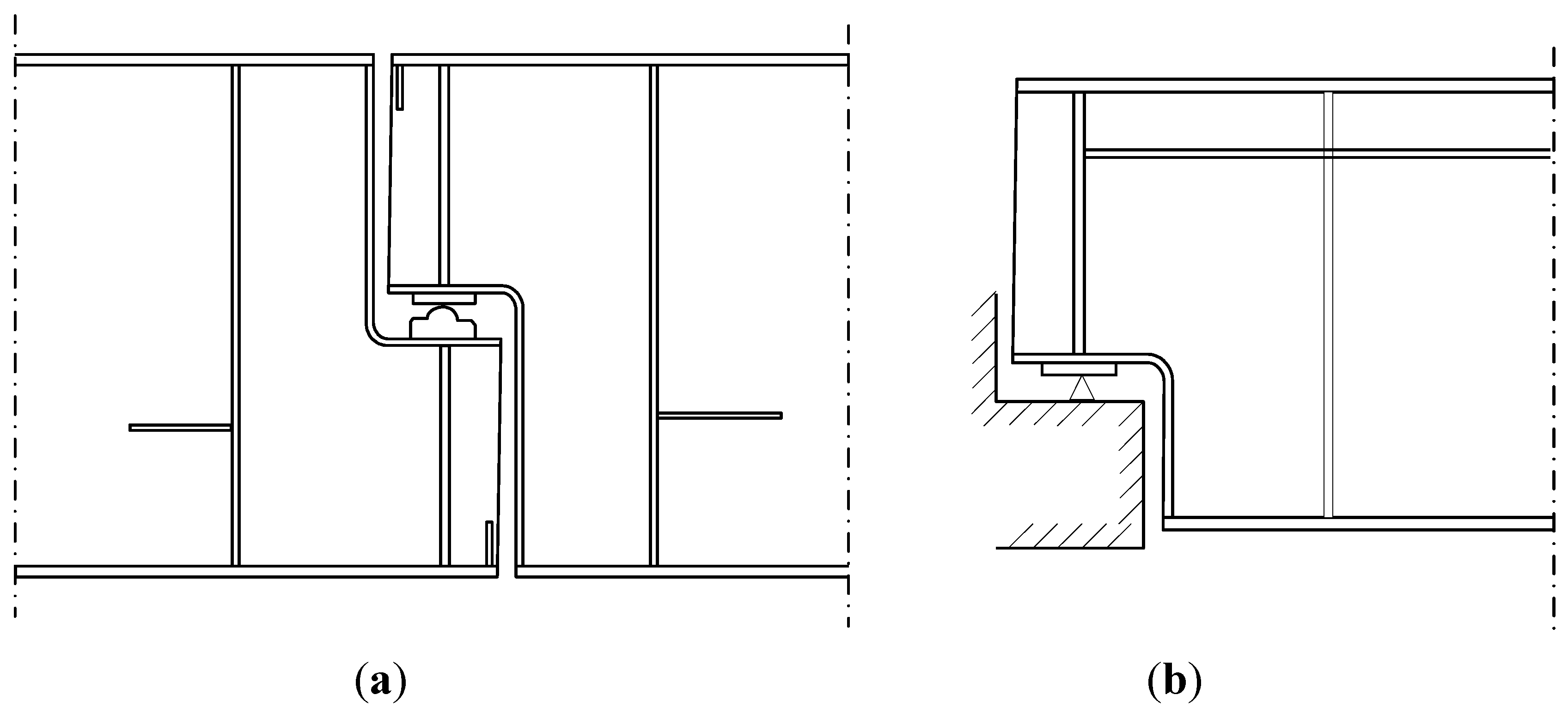
A detail in which numerous fatigue problems have been found in the United States and Japan [5,6] can be found in Gerber bridges and in bridge girders with reduced depth at the supports, Figure 3. According to beam theory, bending stresses in the girder near the support are negligible and the beam is designed at these locations with respect to shear force. Owing to the reduction in girder depth and the resulting change in cross-section, the deformation of the girder will induce additional tangential and radial stresses in the girder web and in the flange-to-web welds along the curvature of the out-cut, see Figure 4.
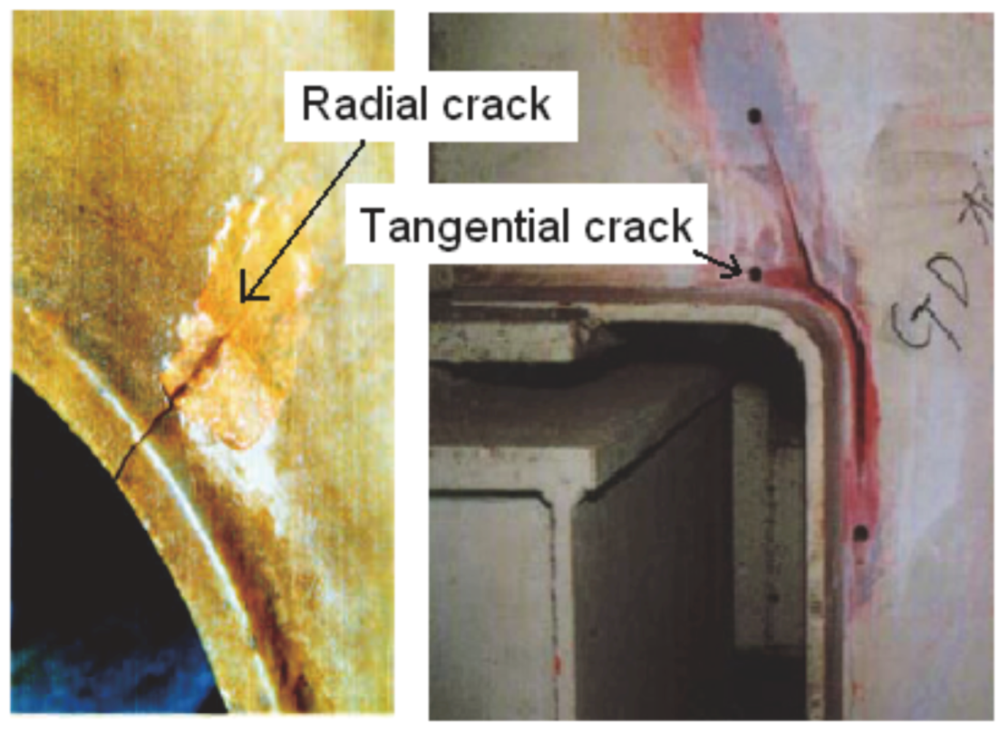
Damage cases involving fatigue cracking in the web of the girder, as well as in the flange-to-web welds, have been reported. In the latter case, the connection between the flange and web was made by means of fillet welds. The cracks in the girder web can grow either in a direction tangential to the flange curvature (caused by the radial stress component) or in a radial direction (generated by the tangential stress component), see Figure 5.
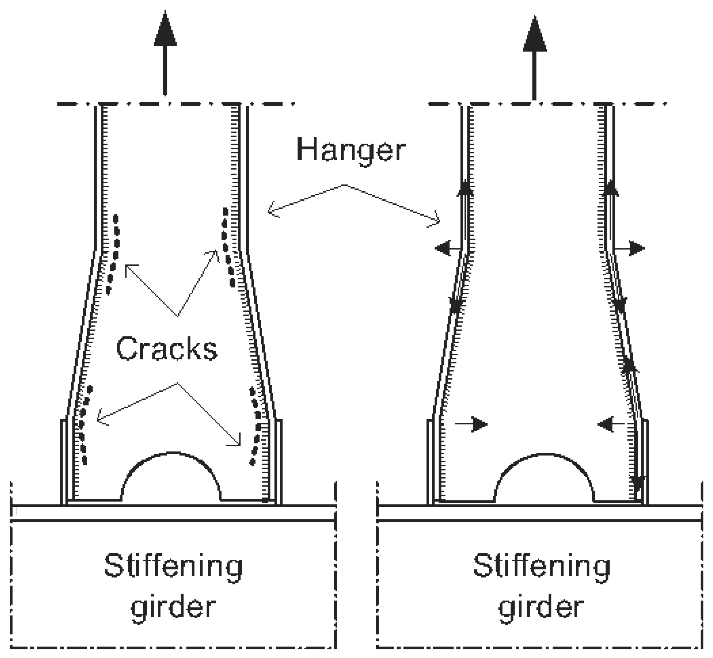
Figure 6 shows another case in which a change in the cross-section of a hanger in an arch bridge resulted in additional stress components that were not taken into account in the design of this member. In this detail, not only the axial stresses in the I-shaped hanger are magnified by the change in cross-section, but also transverse stresses (in the plane of the web) are generated locally at locations where these axial force in the flanges change direction. Fatigue cracks were observed in the web plate in these locations. The crack grew along the fillet weld parallel to the direction of normal axial stresses in the hanger, indicating that they were generated by a stress component perpendicular to the welds.
Figure 3.
Bridge girders with reduced height are common in: (a) Gerber bridges; and (b) At bridge supports.
Figure 3.
Bridge girders with reduced height are common in: (a) Gerber bridges; and (b) At bridge supports.

Figure 4.
Tangential and radial stresses in beams with reduced depth and the three cracking modes that can occur in this detail.
Figure 4.
Tangential and radial stresses in beams with reduced depth and the three cracking modes that can occur in this detail.
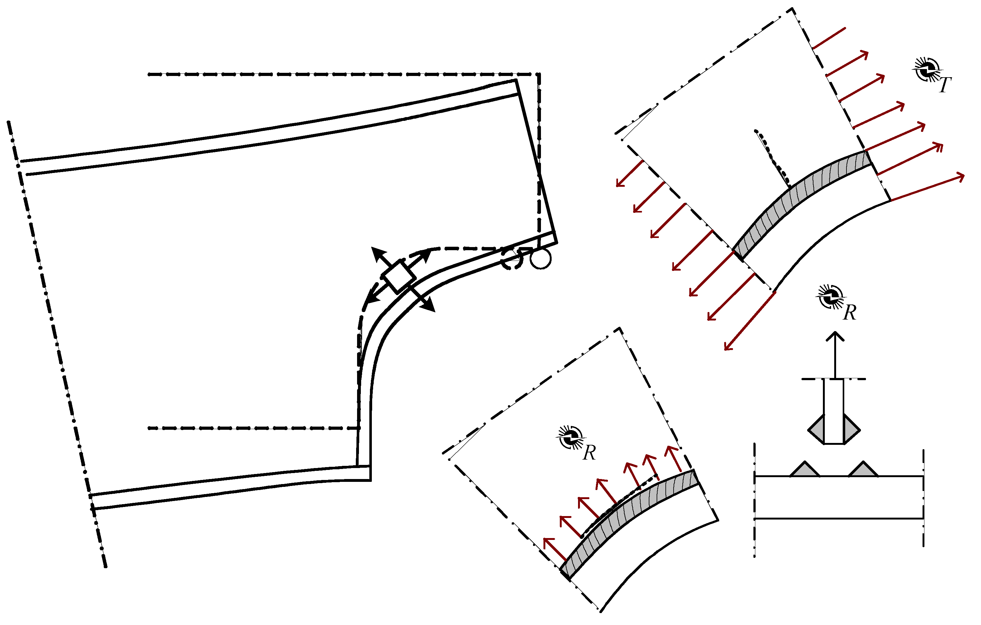
Figure 5.
Examples of radial and tangential cracks [5].
Figure 5.
Examples of radial and tangential cracks [5].

Figure 6.
Fatigue cracking in a vertical hanger with a change in cross-section near its connection to the stiffening girder in an arch bridge.
Figure 6.
Fatigue cracking in a vertical hanger with a change in cross-section near its connection to the stiffening girder in an arch bridge.
4. Vibration-Induced Fatigue Cracking in Bridge Hangers
Vertical hangers in steel arch bridges are usually designed to take care of the axial forces. Details of hanger connections to arch and bridge deck are generally designed to ensure a moment-free connection. For this reason, the hangers are often assumed to be pin-connected at both ends.
Several cases have been reported in which fatigue cracking at the connections of bridge hangers were observed [4,7]. In most cases, a combination of two different mechanisms has contributed to fatigue cracking in these details.
- Vibration: The slender hangers usually have very low bending stiffness, which makes them very sensitive to resonance. The cables can be excited by traffic loads on the bridge and/or wind loads.
- Secondary stresses due to connection stiffness: Ideal moment-free pin connections do not exist in reality. Even when designed as such, a connection will always acquire some rotational stiffness inherent to detailing or gradually during the service life of the bridge, due to corrosion, for example (so-called freezing).
Oscillation of the cables combined with overlooked or unforeseen connection stiffness might result in numerous cycles with a fluctuation in moment (bending stresses) in the hanger near its connections. Even though the magnitude of these bending stresses might be relatively low, the large number of loading cycles caused by vibration may result in fatigue cracking in the detail.
Figure 7 shows an example of an arch bridge in which the hangers have developed fatigue cracks at their connections to the steel arch. This railway bridge, which was built in 1943, has a span of 61 m and comprises a steel arch with two ties (stiffening girders) connected by floor beams. The hangers were made of steel cables with a diameter of 79 mm. A detail of the hanger connection to the steel arch is also shown in Figure 7. The fatigue damage was detected in the early 1980s; some hangers had cracked and totally separated from their connections to the arch. The cracking which took place at the threaded part of the hanger was attributed to a combination of oscillation and secondary bending of the hangers at their connection to the steel arch [7].
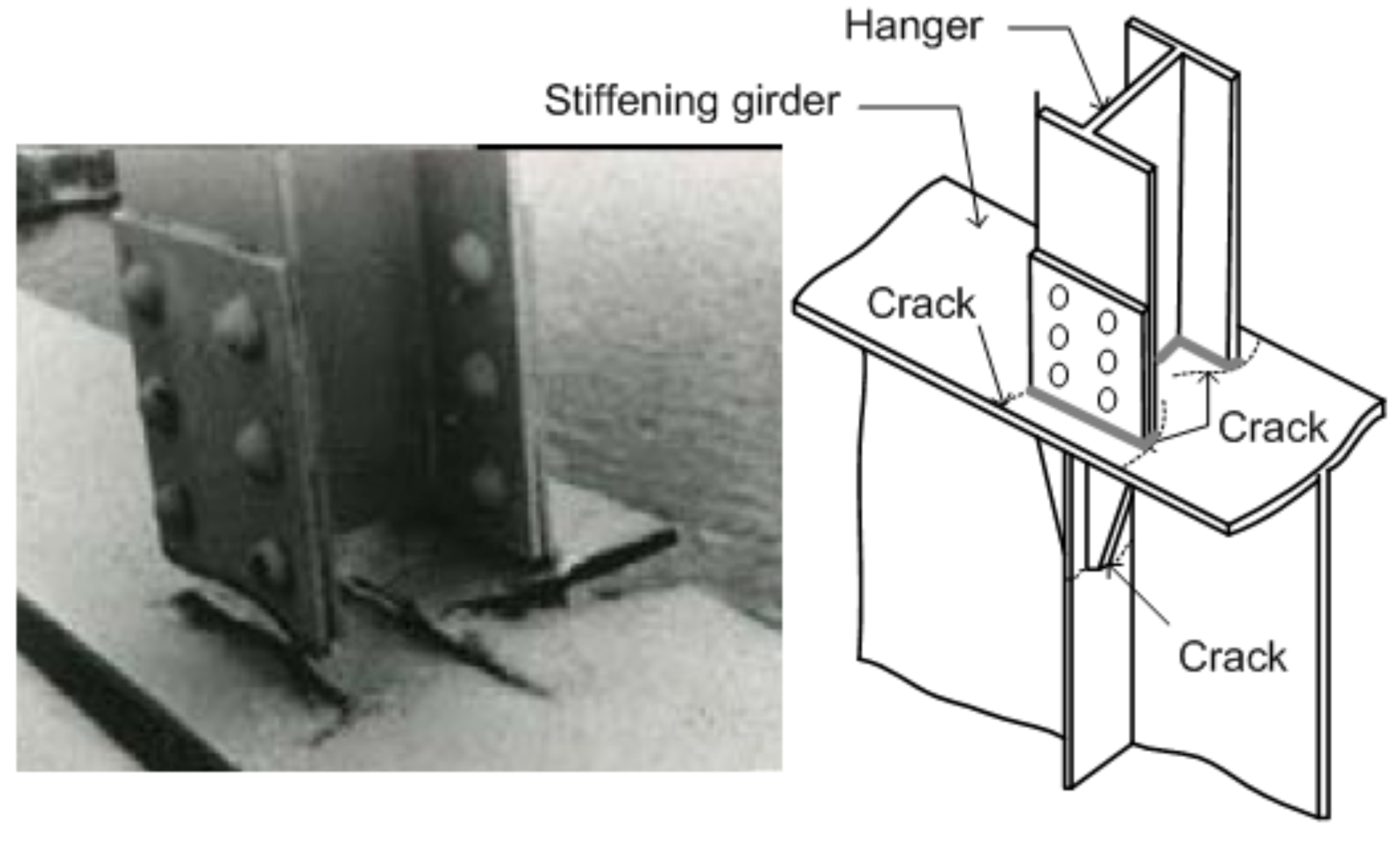
The same mechanisms—often combined with poor detailing of the hanger connection—have led to similar fatigue damage in steel arch bridges in Japan [5]. An example is shown in Figure 8.
Figure 7.
Fatigue cracking of the hangers in the bridge over Skellefte River in Sweden [7].
Figure 7.
Fatigue cracking of the hangers in the bridge over Skellefte River in Sweden [7].
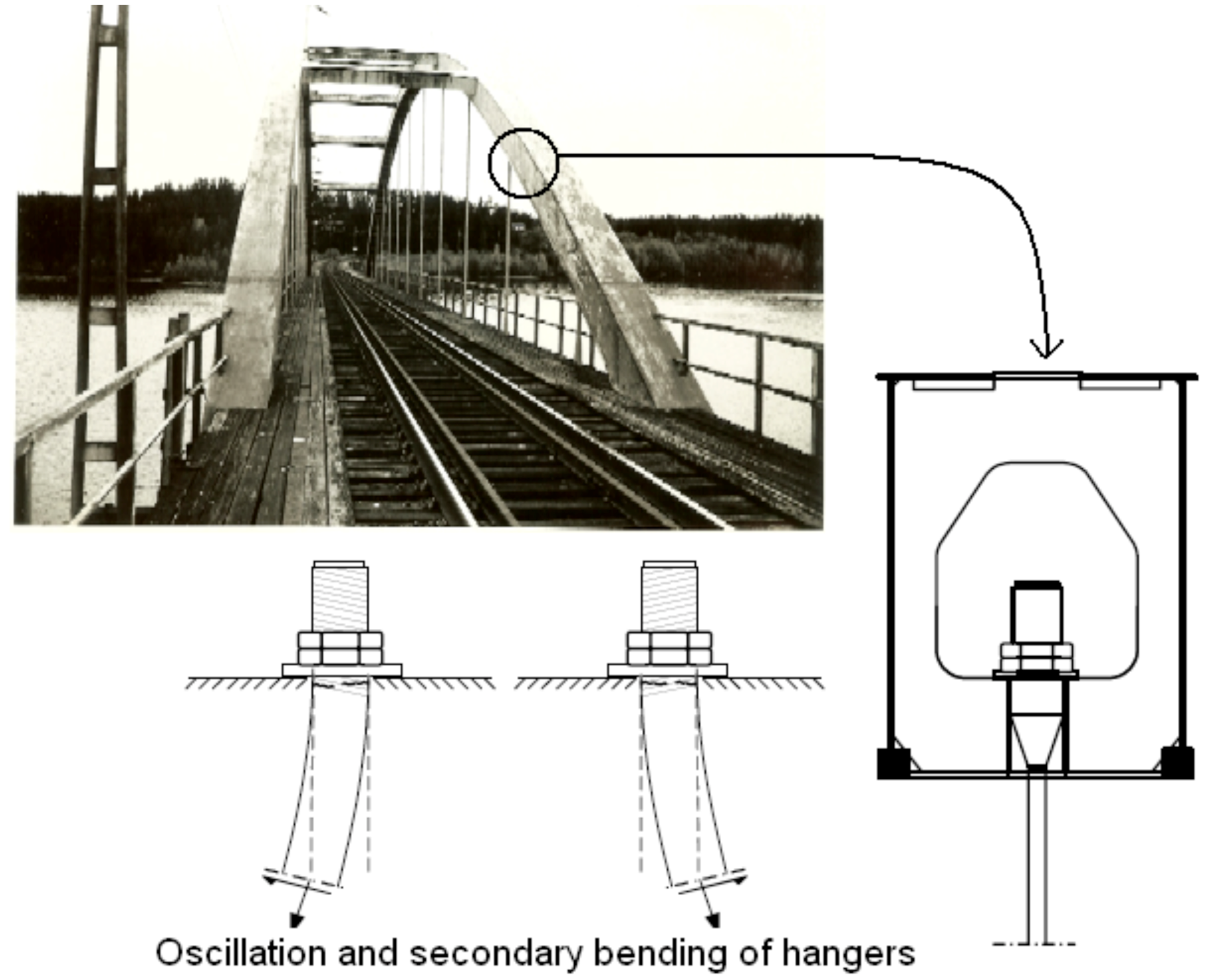
Figure 8.
Fatigue cracking in the hangers of the Mashita Bridge in Japan [5].
Figure 8.
Fatigue cracking in the hangers of the Mashita Bridge in Japan [5].
5. Bridge Girders and Stringers at Timber Tie Connections
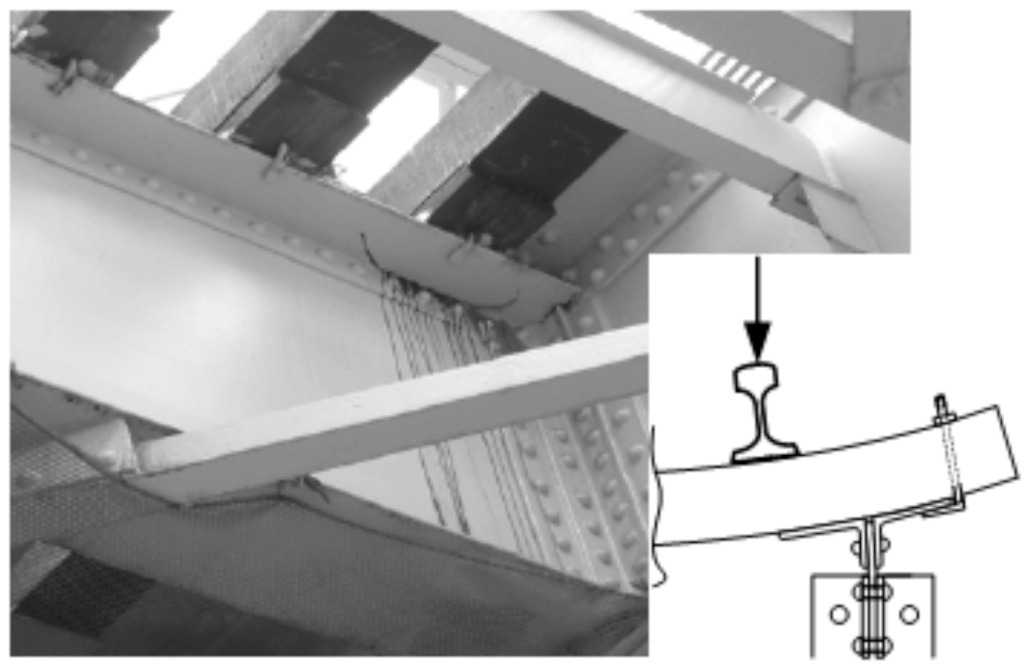
In many old railway bridges, traffic loads on the bridge are transferred to the longitudinal load-carrying members (bridge girders or stringers) via timber ties resting on these members and connected to them by means of hooks or bolts. Several fatigue damage cases in which the stringers exhibited fatigue cracking at locations beneath the timber ties have been reported [8,9]. In welded girders, the cracks often grow along the toe of the welds connecting the girder web to the upper flange. In older riveted girders, the cracks were found along the fillet of one of the L-profiles forming the upper flange of the girder, see Figure 9.
There are two principal actions that may contribute to the initiation of this kind of fatigue cracking.
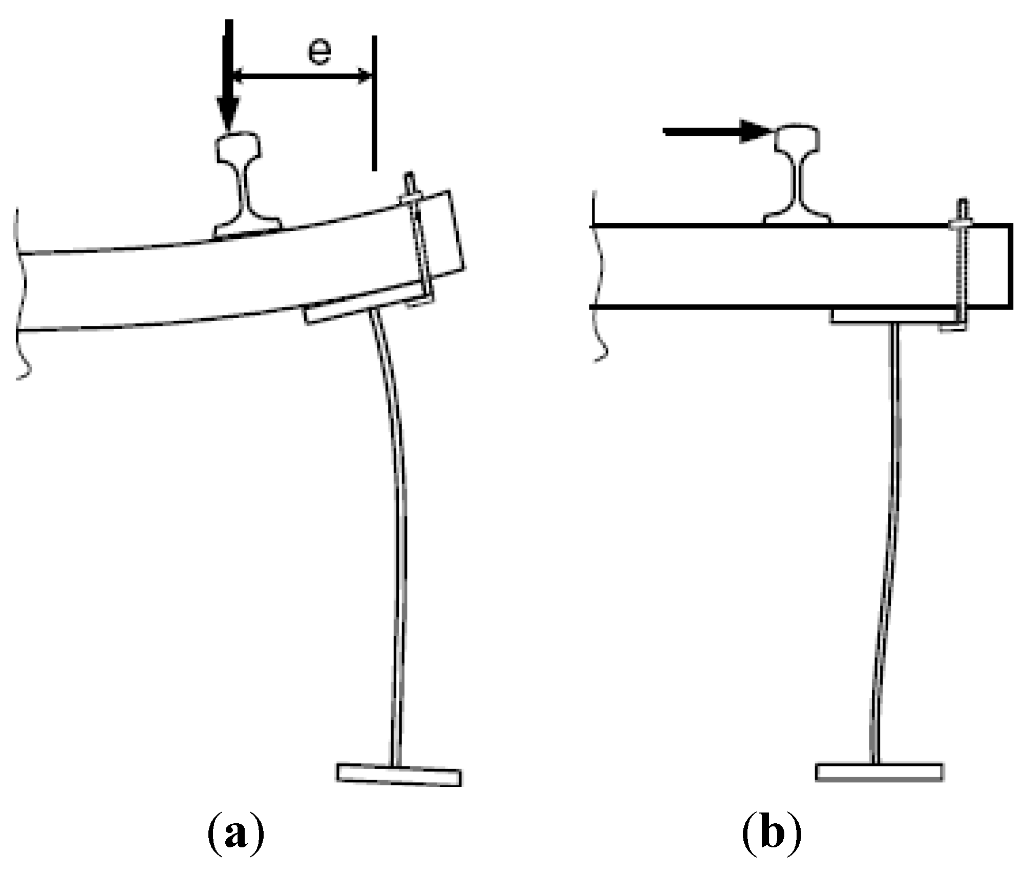
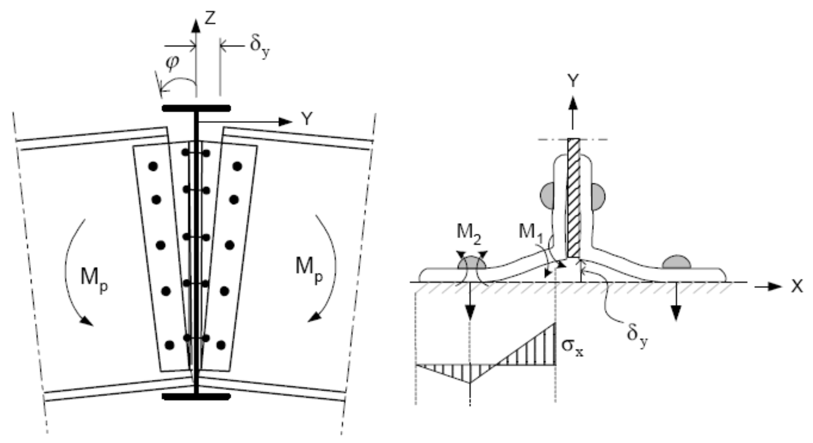
- Bending deformation of the timber ties under the action of vertical axle loads. The corresponding rotation of the ends of the timber tie imposes local bending in the girder flange to which the tie is connected, along with an out-of-plane deformation of the girder web, see Figure 10a.
- Transverse forces on the bridge, causing the out-of-plane bending of the girder web. This effect is more pronounced in curved bridges, but it can also be induced by different track irregularities in straight bridges, see Figure 10b.
Both actions have very short influence lines, giving rise to a large number of loading cycles every time a train passes.
Fatigue damage due to the interaction between bridge girders and timber ties can be mainly found in locations along the girder, where the deformation resulting from this interaction is locally concentrated in flexible areas (i.e., where more global deformation like the one illustrated in Figure 10 is restrained). These locations are, for example, found near the connections of the stringers to the floor beams (see Figure 9) or near diaphragms and cross-bracings, owing to the higher restraining effect at these locations. The concentration of deformation to very small areas in the girder web or to the outstand leg of the girder flange in riveted stringers results in high bending stresses at these locations and leads gradually to fatigue cracking. The same mechanisms result in similar fatigue cracking in highway bridges. The deformation, in these cases, is usually induced by transverse bending of the concrete deck which acts compositely with steel girders.
Figure 9.
Example of fatigue cracking in stringers at timber tie connections [8].
Figure 9.
Example of fatigue cracking in stringers at timber tie connections [8].

Figure 10.
Schematic figure showing the deformations induced in a bridge girder as a result of: (a) Bending deformation due to rail eccentricity; and (b) Transverse forces.
Figure 10.
Schematic figure showing the deformations induced in a bridge girder as a result of: (a) Bending deformation due to rail eccentricity; and (b) Transverse forces.
6. Diaphragms and Cross-Bracing Connections
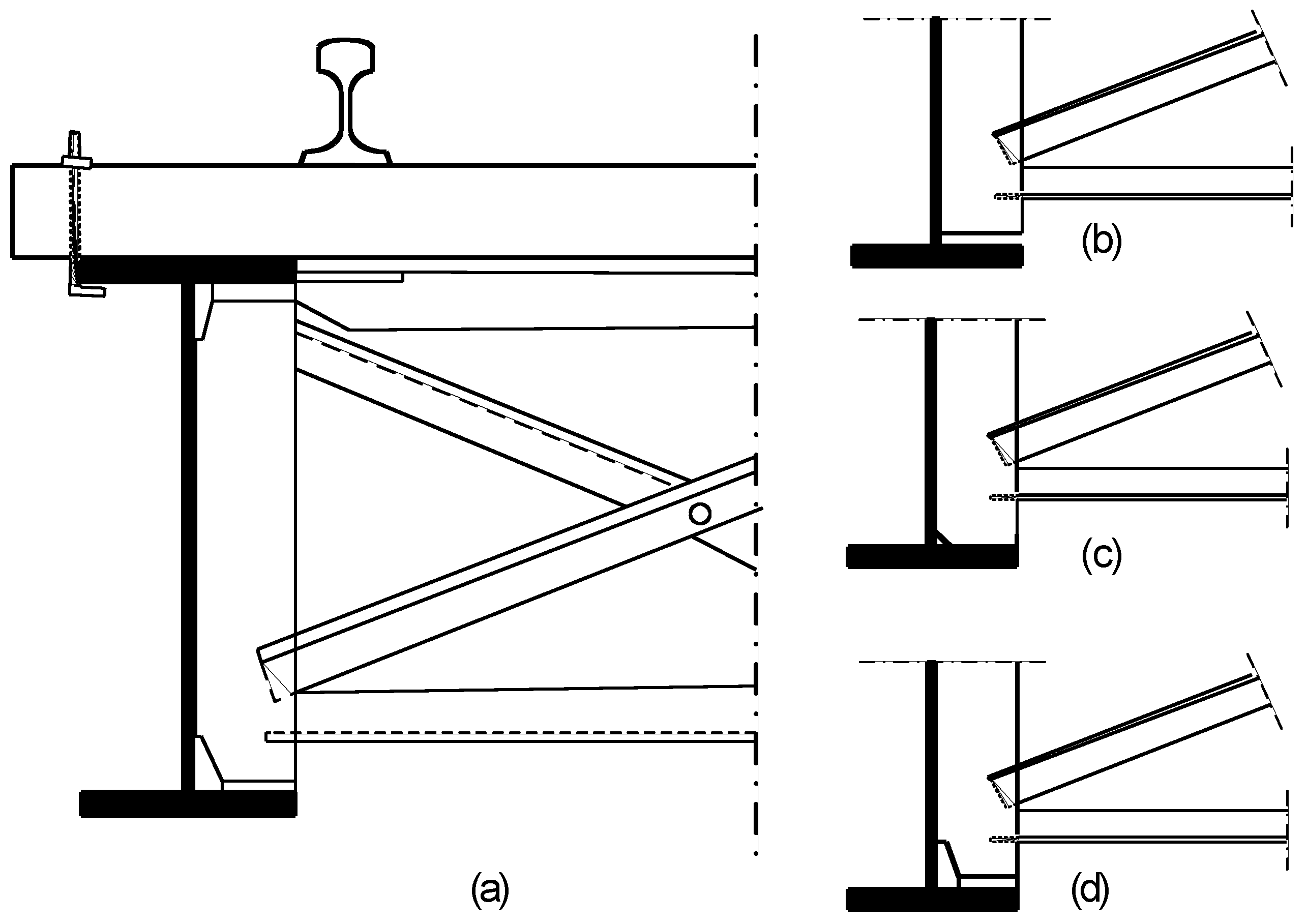
Diaphragms and cross-bracings are vital elements which are used in many bridge types to ensure the lateral stability of the bridge structure during construction and/or against lateral and torsional loads acting on the bridge. In many cases, these stabilizing elements are connected to the longitudinal members of the bridge (main girders or stringers) through connection plates, which are welded, bolted or riveted to the girder web. In welded bridges, the common practice for many years has been to omit the welds connecting the vertical stiffeners to the girder flange in order to avoid a detail with low fatigue strength. Instead, the connection plate is either cut short a distance from the flange or fitted to the flange, either directly or via a piece of steel as a filler plate fitted underneath the stiffener, see Figure 11b–d.
Figure 11.
Detailing of the connection of cross-bracing elements to bridge girders.
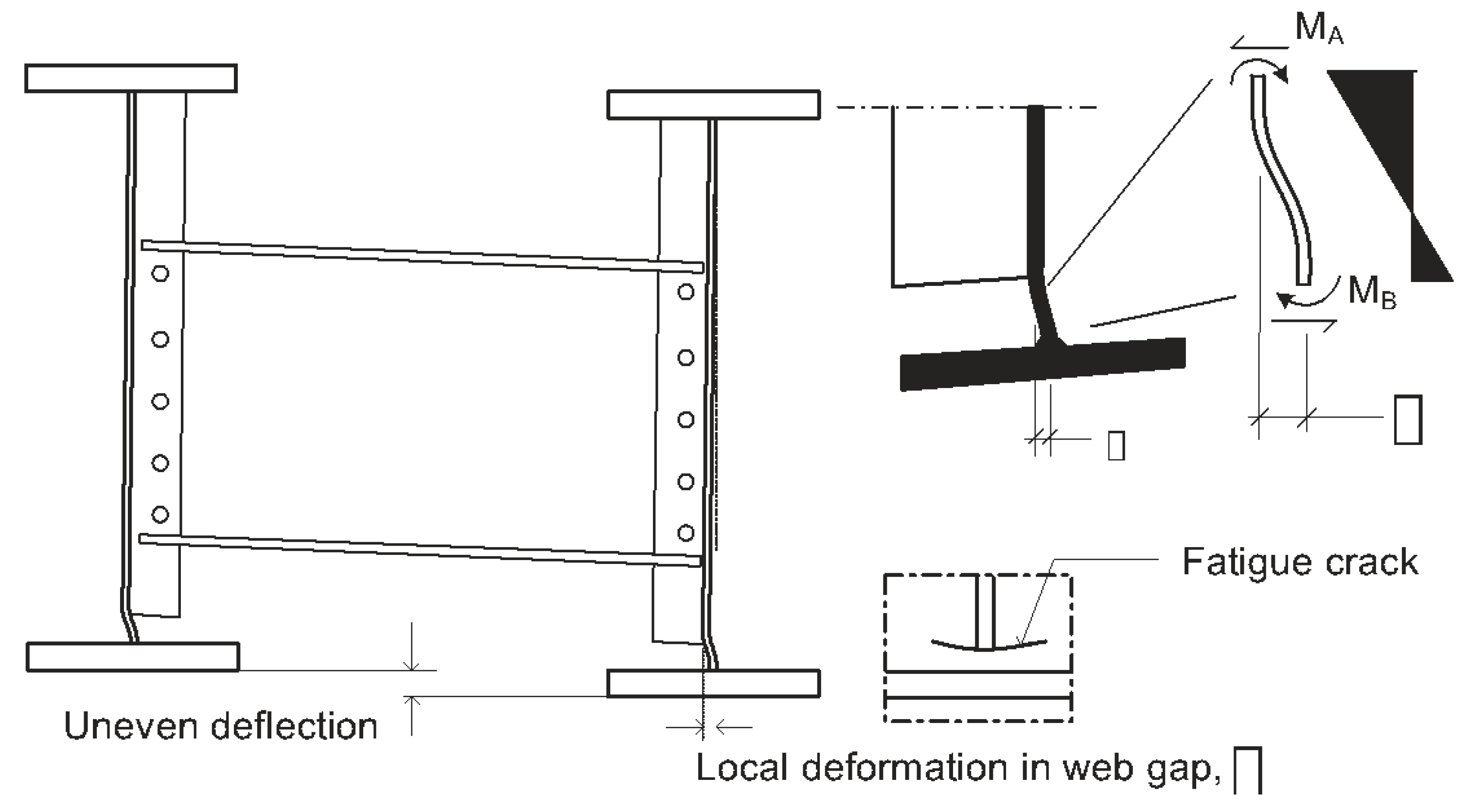
The detail near the termination of transverse plates (or vertical stiffeners) used to connect diaphragms or the cross-bracing is known to be one of the most critical in terms of fatigue in steel bridges. Fatigue cracking here is primarily found in the girder web, starting at the end of the stiffener and growing almost horizontally in a direction parallel to the normal bending stresses in the web, see Figure 12. This type of fatigue cracking has been reported in both railway and highway bridges and can be found in many bridge types, including two- and multi-girder bridges, box girder bridges and truss bridges. The mechanism behind fatigue cracking at diaphragm and cross-bracing connections is, however, the same, irrespective of bridge type. Loading cases, which result in secondary bending of the bridge girders (in the weak direction) and/or torsional deformation of the bridge cross-section, cause uneven deflection of the girders, which is resisted by the diaphragm or the cross-bracing elements. Consequently, tensile and compressive forces are generated in these elements, acting perpendicular to the plane of the girder web and causing secondary bending stresses which are localized in the unstiffened part of the web between the girder flange and the end of the connection plate, see Figure 12.
In railway bridges, these transverse and torsional loads are more obvious in curved and skewed bridges, but they may also be generated in straight bridges by possible track eccentricities or irregularities. The same effects are clear in highway bridges where the truck load can take any position in the transverse direction of the bridge, causing uneven deflection of the bridge girders.
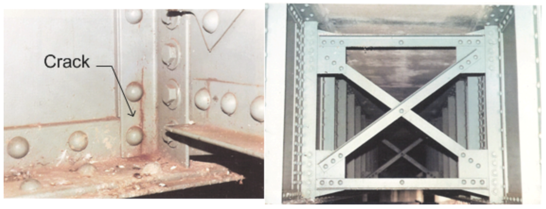
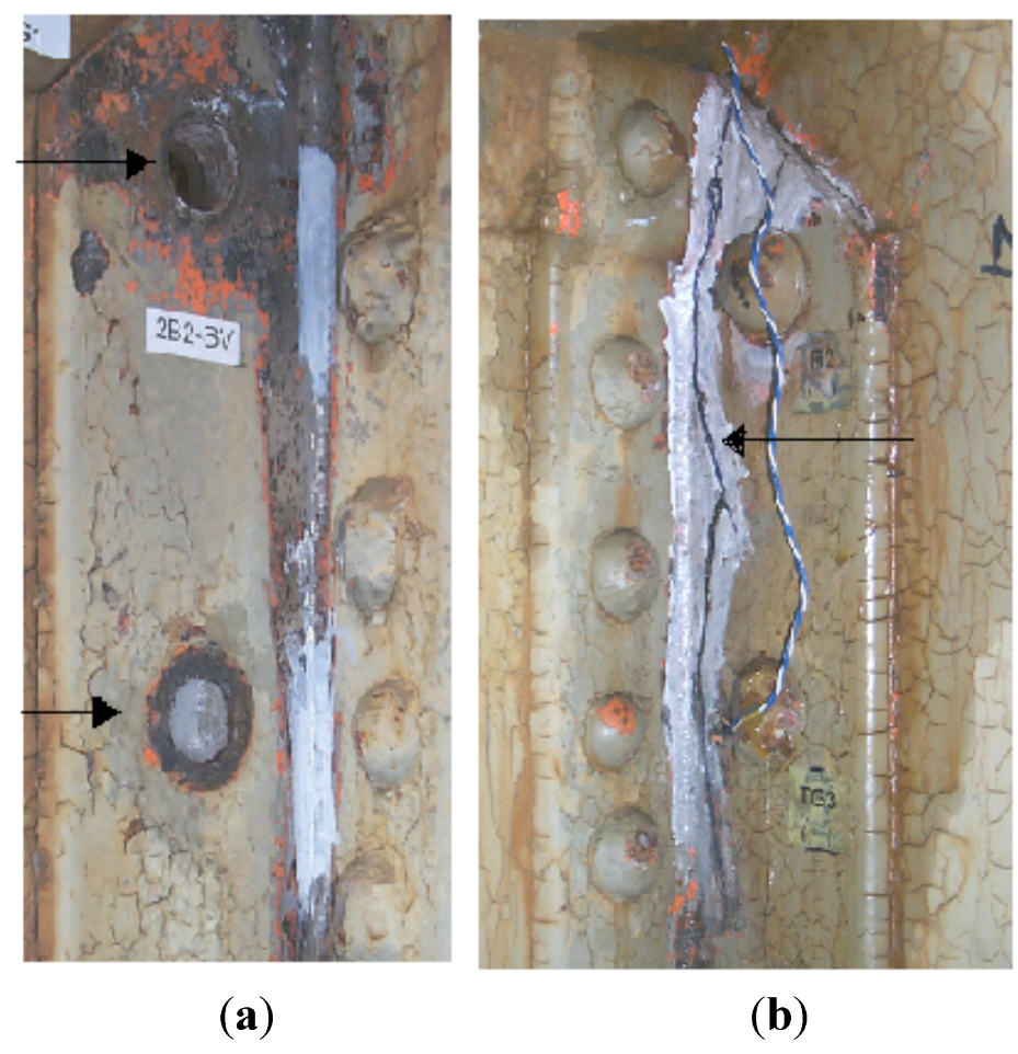
Furthermore, riveted connections of the type discussed here have also been shown to be prone to fatigue cracking [10]. In this case, the fatigue damage is found either in the outstand leg of the connection angle or in the rivets connecting the angle to the girder web, see Figure 13.
Figure 12.
The differential deflection of bridge girders results in high local bending stresses in unstiffened web gaps between the girder flange and the termination of cut-short connection plates.
Figure 12.
The differential deflection of bridge girders results in high local bending stresses in unstiffened web gaps between the girder flange and the termination of cut-short connection plates.

Figure 13.
Fatigue cracking in the riveted connection of cross-bracing elements [11].
Figure 13.
Fatigue cracking in the riveted connection of cross-bracing elements [11].
7. Stringer-to-Floor-Beam Connections
In many existing bridges, mechanically fastened stringer-to-floor-beam connections are made using double angles riveted or bolted to the web plates of both members. The common engineering practice has been to design these connections to take account of shear forces alone (their load-carrying function being to transfer the stringer end reactions to the floor beam). While this assumption may be adequate for the ultimate limit state design, the behavior of these connections under moderate loads might differ substantially.
Connections of this type have displayed high vulnerability to fatigue cracking. A large number of damage cases in which fatigue cracks were detected in the connection angles have been reported [12,13]. The cracks usually start at the outstand leg of the connection angle and grow along the fillet of the angle. Figure 14b shows an example of this kind of fatigue cracking.
Figure 14.
Example of fatigue damage in stringer-to-floor-beam connections [12]: (a) at the junction between the rivet head and shank; (b) at the external leg of the connection angle.
Figure 14.
Example of fatigue damage in stringer-to-floor-beam connections [12]: (a) at the junction between the rivet head and shank; (b) at the external leg of the connection angle.

In old riveted connections, rivet failures are also very common. Here, cracking starts in the junction between the rivet head and shank (caused by prying and rivet bending) and finally results in the total separation of the rivet head, see Figure 14a. Fatigue damage of this kind is generally located at the top of the connection, but cases of damage with fatigue cracking and/or rivet failure at the bottom of the connection have also been reported [12].
Fatigue cracking in stringer-to-floor-beam connections is generated by secondary effects which are deformation induced in nature. Two mechanisms can be identified here.
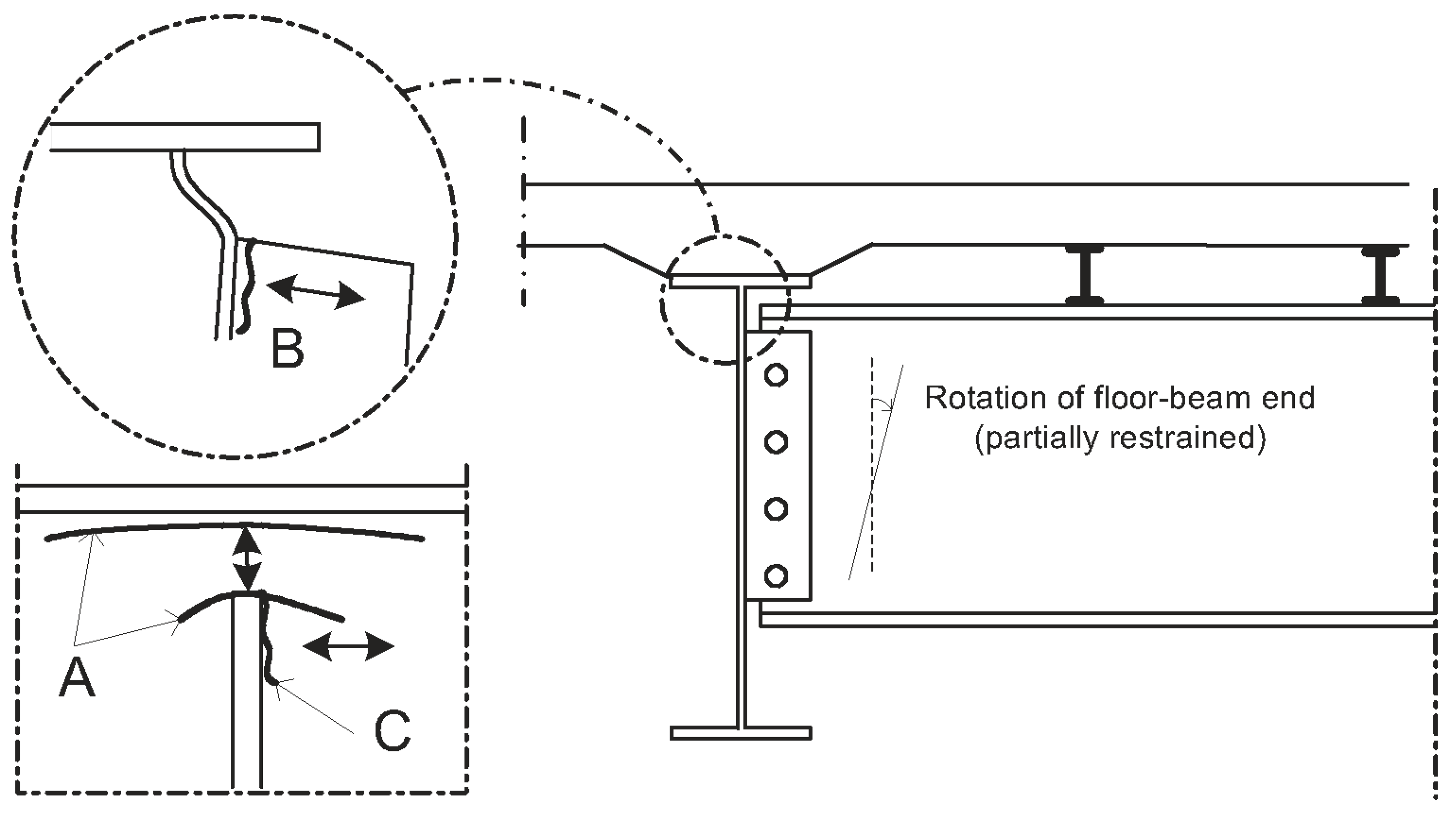
The rotation of stringer ends associated with bending. Even though double-angle connections were designed as simple shear connections, it is generally inevitable that these connections also acquire some rotational stiffness, thus partially restraining the rotation of stringer ends. Consequently, negative bending moment will develop at the ends of the stringers, subjecting the fasteners and the angles of the connections to load effects which are not taken into account during design, see Figure 15. This kind of action has a relatively short influence line, giving rise to a large number of loading cycles during the service life of the bridge.
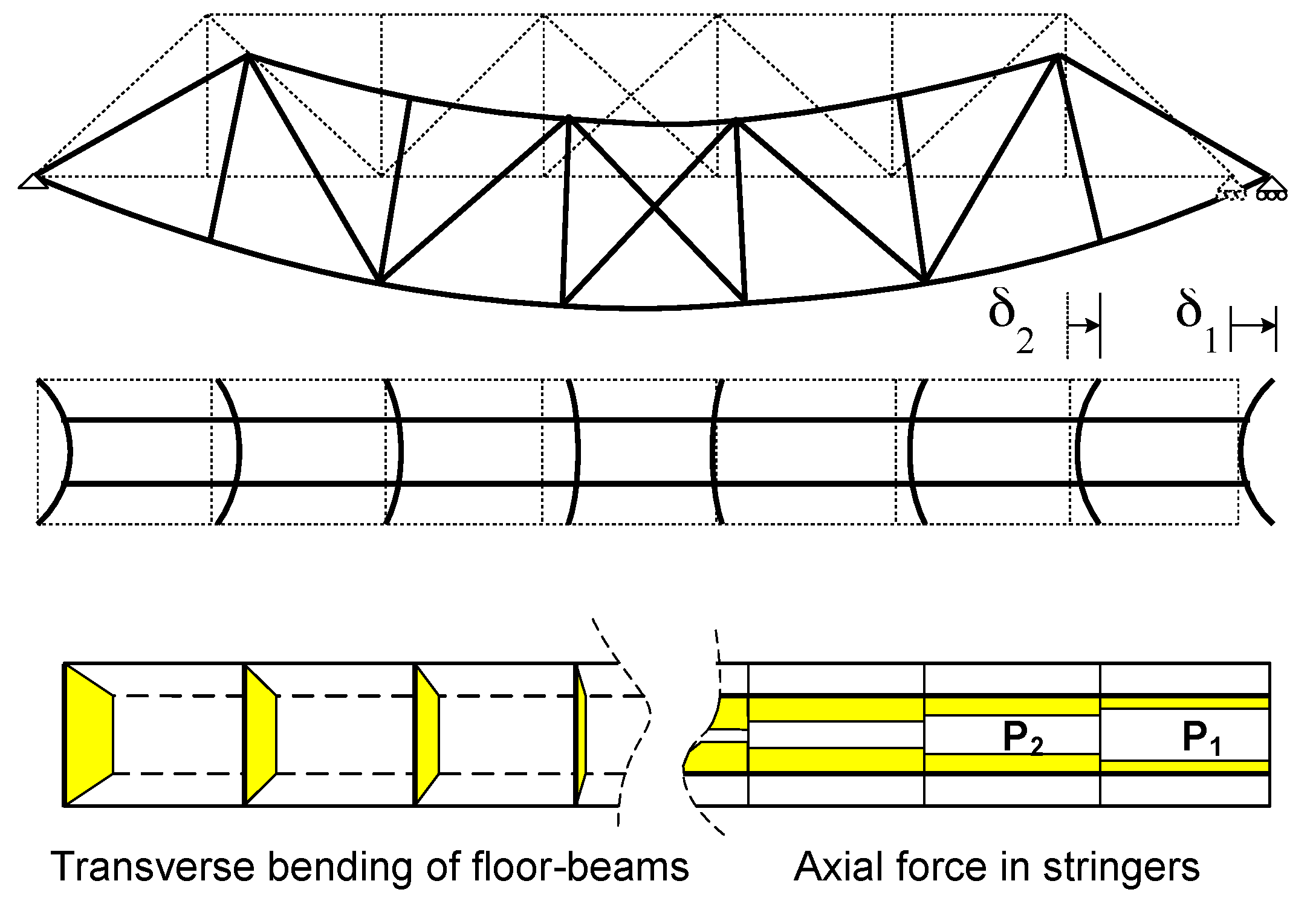
An overlooked interaction between the floor system (stringers and floor beams) and the main load-carrying structure (main girders or main trusses, for example). Bending deformation of the main truss bridge, for instance, involves the longitudinal displacement of the truss joints to which the floor beams are connected. The floor beams are, however, partially restrained from following this deformation due to the axial stiffness of the stringers and their connections to the floor beams. As a result, secondary axial forces will develop in the stringers and their connections to the floor beams, while the latter will be subjected to secondary bending (in the weak axis), see Figure 16. This kind of interaction has an influence line, which is equal to the span of the bridge and, in the case of railway bridges, there is essentially one loading cycle every time a train passes.
Figure 15.
Secondary bending at stringer ends due to restrained end rotation. Bending and axial stresses at the top of the stringer-to-floor-beam connection might be high enough eventually to result in fatigue cracking.
Figure 15.
Secondary bending at stringer ends due to restrained end rotation. Bending and axial stresses at the top of the stringer-to-floor-beam connection might be high enough eventually to result in fatigue cracking.

Figure 16.
The interaction between the floor system (stringers and floor beams) and the main bridge trusses results in secondary axial forces and bending moment in the stringers and the floor beams, respectively.
Figure 16.
The interaction between the floor system (stringers and floor beams) and the main bridge trusses results in secondary axial forces and bending moment in the stringers and the floor beams, respectively.
Fatigue cracks in the double angles of stringer-to-floor-beam connections are generated by bending stresses and are therefore somewhat difficult to detect in the early stages, i.e., before the surface crack grows through the thickness of the connection angle. Fatigue tests on bridge parts including riveted double-angle connections show, however, that the propagation rate of these cracks is very low [12]. The presence of these cracks directly does not threaten the integrity of the load-carrying function of the floor system. However, in one case at least, fatigue cracking in stringer-to-floor-beam connections was reported to result in the total separation of the stringer, a failure mode which might jeopardize the entire performance of the bridge (International Institute of Welding).
8. Connections between Floor Beams and the Main Load-Carrying Members
Like stringer-to-floor-beam connections, connections between floor beams and main load-carrying elements or system (main girder, main trusses, arch ties, etc.) have also displayed numerous fatigue problems. In principle, the interaction mechanisms behind fatigue cracking in these two types of connection are the same. Secondary bending moment (in the plane of floor-beam web) might develop at the ends of floor beams as a result of the rotational restraint provided by their connections to the main load-carrying elements. Furthermore, the interaction between the floor system (stringers and floor beams) and the main load-carrying structure might result in secondary out-of-plane bending of the floor beams, as illustrated in Figure 16.
Figure 17 and Figure 18 show two examples of fatigue cracking caused by the restrained rotation of floor-beam ends. In mechanically fastened connections, the fatigue damage is generally found in the connection angles or the rivets (or bolts) connecting the angles to the main load-carrying element [5,14], see also Figure 15. In welded details, where the floor beam is connected to a welded transverse plate, cracking has been reported in the main girder web (types A and C in Figure 18) or in the connection plate along its fillet weld to the main girder web (type C) [4,5,10].
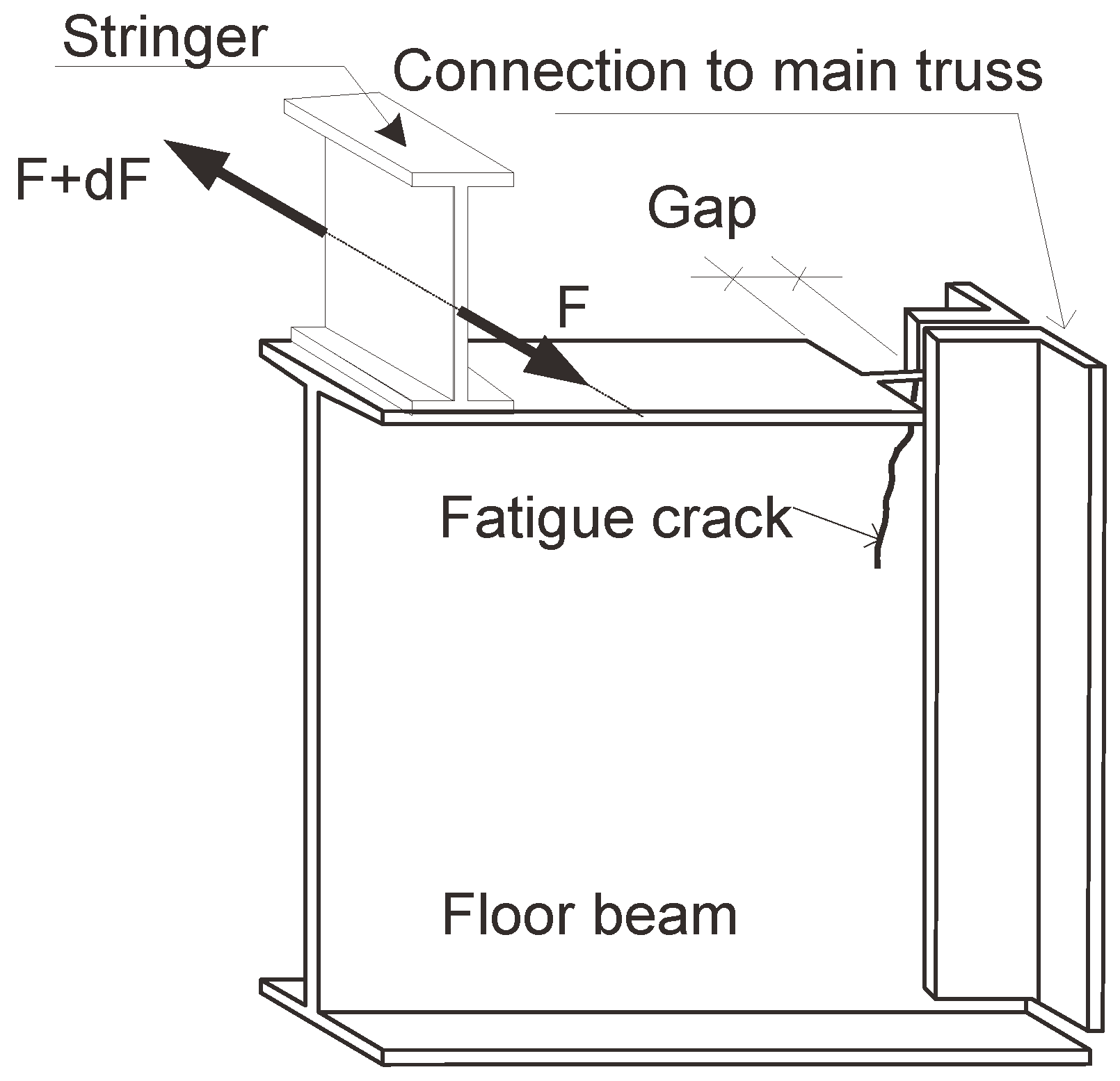
The second type of interaction (transverse bending of the floor beams) has also resulted in fatigue damage in many steel bridge types. One example is shown in Figure 19. In this case, the upper flange of the floor beam is cut short near the floor beam to main truss connection, leaving a small—locally flexible—gap in the floor-beam web where the deformation is concentrated. Is such a case, after crack initiation, further propagation of the fatigue crack is derived by the secondary bending stress in the floor beam near the connection. The same kind of fatigue cracking has been reported for highway girder bridges [4,10], truss bridges [5] and arch bridges [14,15].
Figure 17.
Fatigue damage in a floor beam riveted to the main truss connection as a result of the restraining effect.
Figure 17.
Fatigue damage in a floor beam riveted to the main truss connection as a result of the restraining effect.
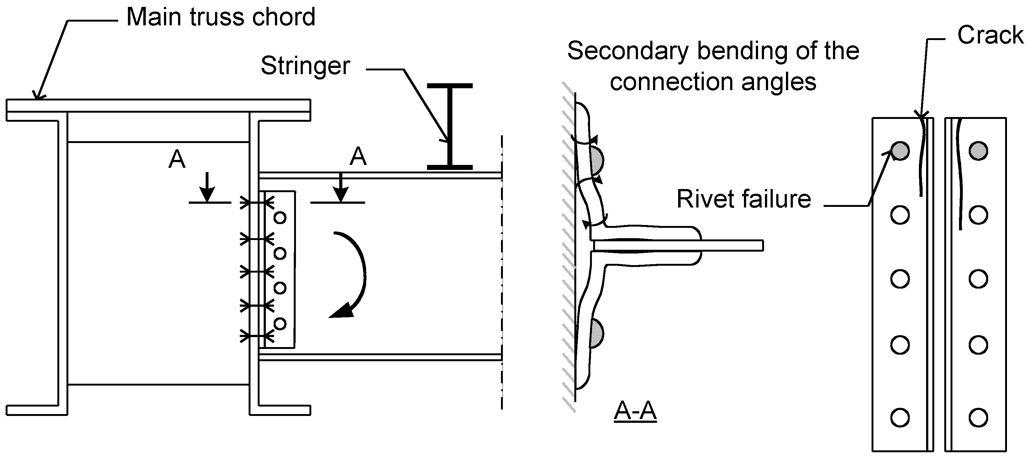
Figure 18.
Fatigue cracking in a floor beam welded to the main girder connection.

Figure 19.
Fatigue cracking in the floor-beam web caused by the transverse bending deformation generated by the interaction between the floor system and the main trusses in the bridge.
Figure 19.
Fatigue cracking in the floor-beam web caused by the transverse bending deformation generated by the interaction between the floor system and the main trusses in the bridge.
9. Elements with Coped Ends and Cut-Short Flanges
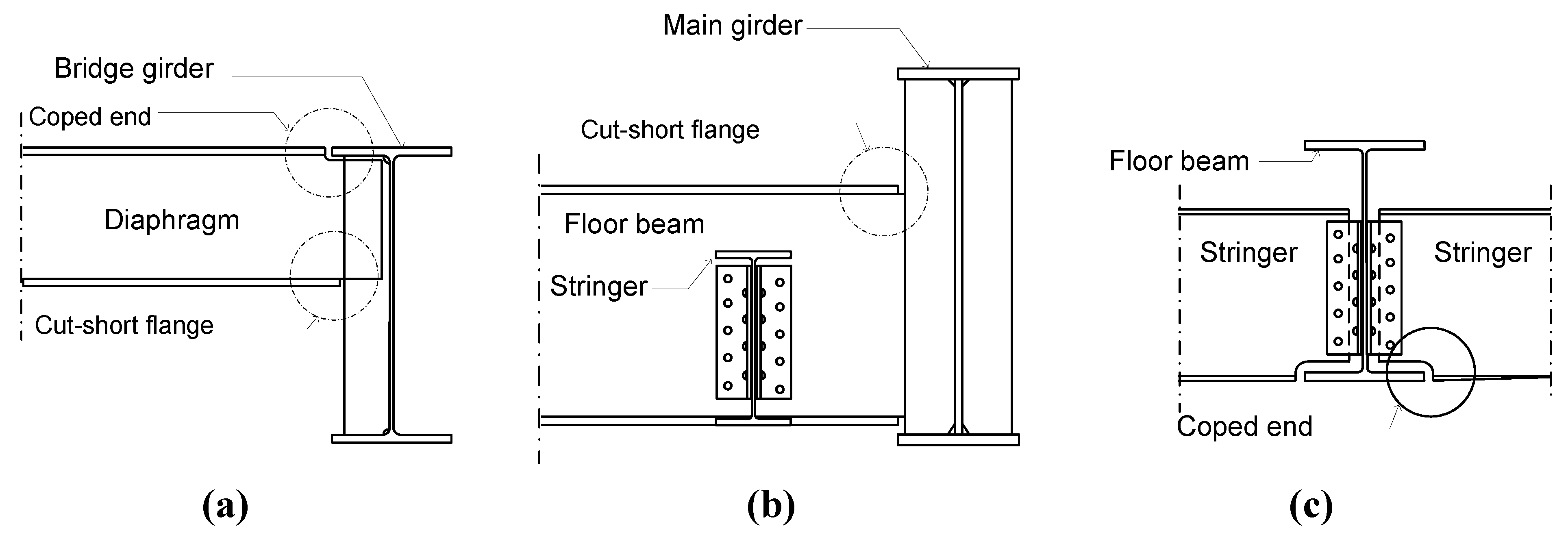
In order to facilitate their connection to other elements in the bridge, diaphragms, stringers and floor beams frequently have coped ends or cut-short flanges at their connections, see Figure 20. These elements have often been shown to be susceptible to fatigue cracking [4,5,15,16]. In general, the cracks start and grow in the web of the element in the areas that are weakened locally by coping or flange short-cutting.
Figure 20.
Examples of bridge elements with coped ends or cut-short flanges: (a) diaphragm; (b) floor beam; and (c) stringer.
Figure 20.
Examples of bridge elements with coped ends or cut-short flanges: (a) diaphragm; (b) floor beam; and (c) stringer.
The same kinds of secondary effect described in 6 to 8 above apply here. In addition, coping or short-cutting of the flange may contribute to earlier fatigue cracking in several ways.
- By removing parts of the beam flanges near the end, the section modulus of the beam is substantially reduced. Secondary bending due to restrained end rotation may therefore result in relatively high bending stresses in the web near the end connection.
- The area near the coped end or the cut-short flange is also a location of stress concentration, which further reduces fatigue resistance.
- Sometimes the ends are coped using flame cutting without post-treatment resulting in rough edges. The residual stresses generated by the cutting process may also contribute to early fatigue damage development in these elements.
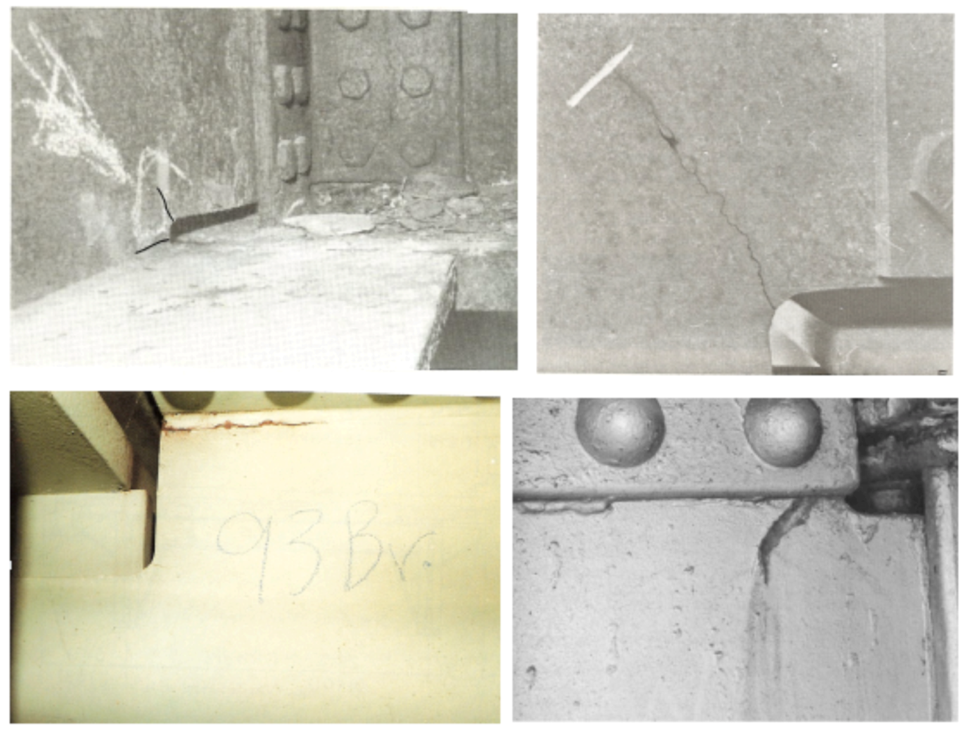
Figure 21 shows some examples of fatigue cracking in various elements with coped ends or cut-short flanges at their connections to other elements.
10. Connections between Girder Splices
In many long-span bridges, the steel girders are usually fabricated in several segments due to transportation limitations and sectional changes. Consequently, the assembly of steel girder segments is carried out on-site through welded or riveted connections. When welded connections are used, cut-outs in the girder’s web are introduced at its intersections with the flanges to facilitate for transversal butt welds and avoid weld crossing. The web cut-outs, also known as cope-holes, have shown to be susceptible to fatigue cracking in several studies [11,17,18]. The fatigue crack initiation site is often reported to be at the fillet weld toes of the cope-hole; where it can grow either in the web or across the flange, see Figure 22.
Figure 22.
Examples of fatigue cracking in bridge girders with cope-holes at severe stress concentration locations [11].
Figure 22.
Examples of fatigue cracking in bridge girders with cope-holes at severe stress concentration locations [11].

The mechanisms that may lead to fatigue cracking of girders at cope-holes can be categorized under two principally different subgroups:
- The abrupt introduction of stress raisers at the flanges. Flanges are the outermost elements of steel girders which according to the beam theory are subjected to the maximum normal stresses in bending. Cut-outs in the web and corresponding welds at the intersection with flanges, introduce severe areas of stress concentration perpendicular to the maximum stress direction.
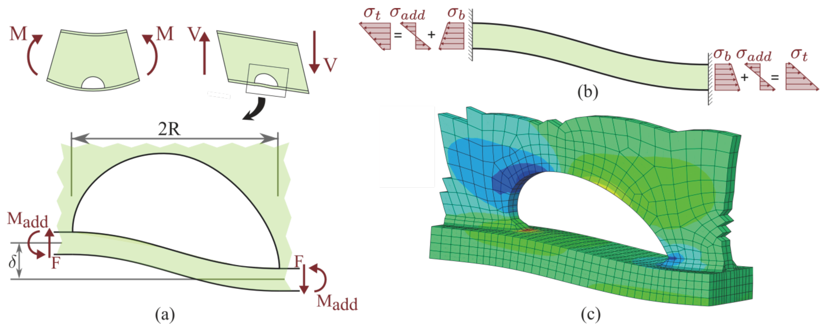
- Secondary stresses due to shear deformation of the girder. Although the shear deformation of stiff long-span girders is generally neglected in design, the local effects of such deformations may be significant. As can be seen in Figure 23, as a result of existing shear, a relatively small displacement (δ) is induced between the sections before and after a cope-hole. However, as the lateral support of the flange provided by the web is no longer available in this section, the flange undergoes an additional deformation. In this instance, the flange is analogous to a beam with both ends fixed sustaining an additional moment (Madd). This deformation gives rise to the stresses acting on the weld toe at one end and decreases them at the other end.
Figure 23.
(a) Bending and shear deformation of a section with cope-hole; (b) Stress distribution through flange thickness at weld toe; (c) 3D finite element model.
Figure 23.
(a) Bending and shear deformation of a section with cope-hole; (b) Stress distribution through flange thickness at weld toe; (c) 3D finite element model.

The influence line of such mechanisms is limited to a small area and thus, a large number of loading cycles in each train passage are influenced. Furthermore, the effect of secondary stresses due to shear deformation becomes prominent in sections where the ratio of shear stress to normal stress increases [19]. Therefore, special attention should be given during the design phase to place the splices at less vulnerable locations.
11. Welded Cover-Plates
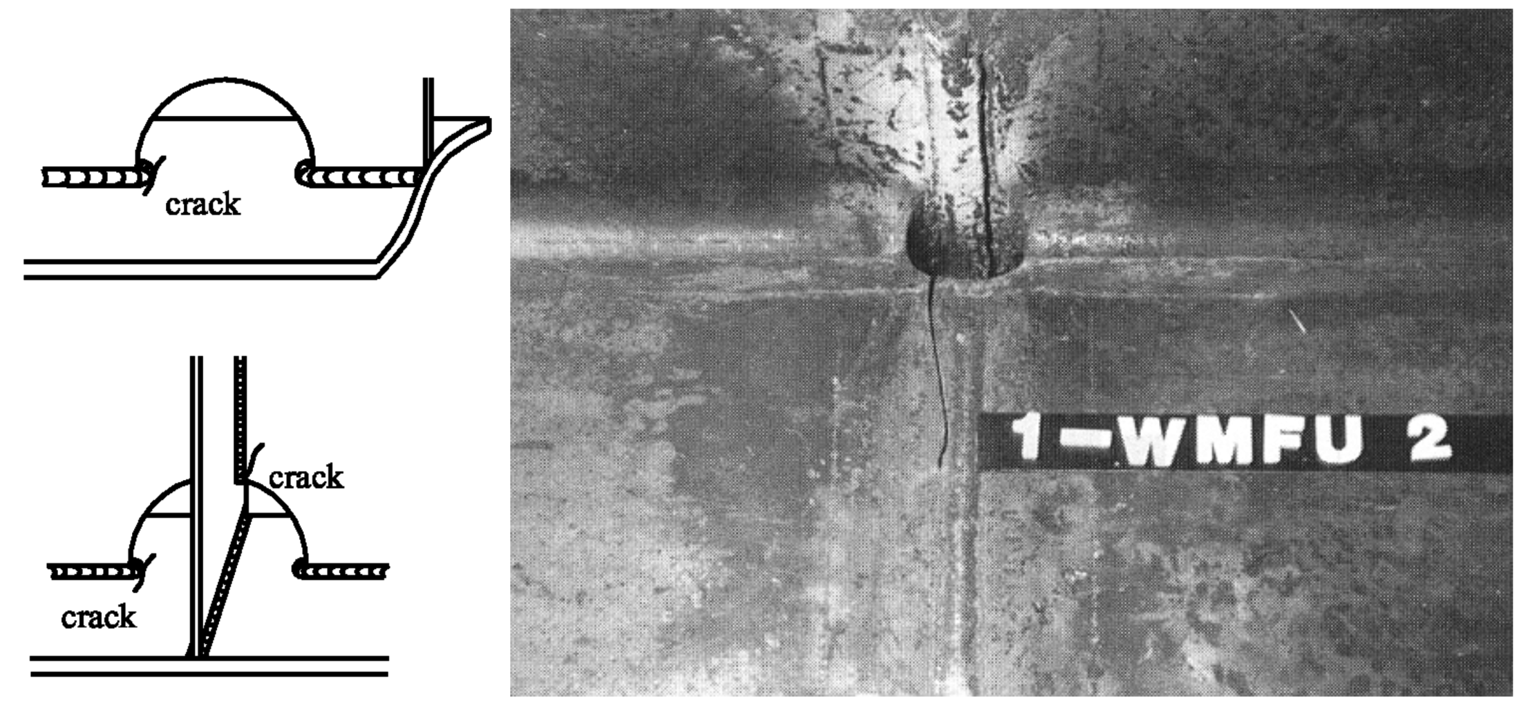
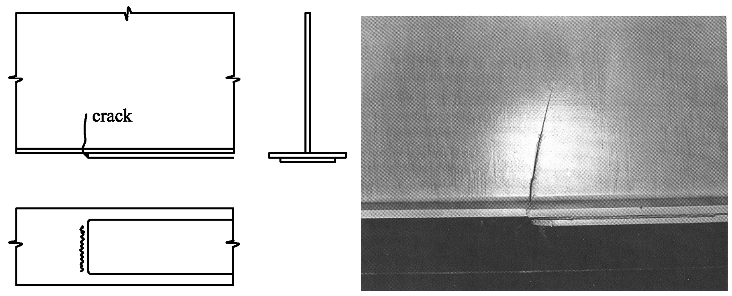
Partial-length cover-plates are usually welded to the flanges of steel bridge girders in order to increase the moment capacity and, consequently, the allowable traffic load and span of the bridge. However, fatigue cracks have been discovered numerously at the cover-plate ends in strengthened members [4,20]. The cover-plate end has the least fatigue strength of all details and is considered as a lower bound of the fatigue strength of welded details in a bridge girder [21]. The most eminent examples of such failures are the large number of discovered fatigue cracks at the cover-plate ends in the Yellow Mill Pond bridges, Connecticut during 1970s and the King’s Bridge, Melbourne, Australia.
Fatigue cracks of this kind initiate at the weld toe of cover-plate transverse end weld and begin to develop in the web, once propagated through the entire flange width, see Figure 24. The main cause of such low behavior of cover-plate ends is associated with the expeditious change of sectional stiffness before and after the welded cover-plate, which causes severe stress concentration at the cover-plate end. In addition to that, the inevitably formed micro-cracks at the weld toe, as a consequence of welding process, accelerate the fatigue failure. Furthermore, it is reported that when the transverse end weld is omitted, the fatigue strength does not improve [22]. Besides, in such cases, other degradation mechanisms such as corrosion caused by trapped water between the cover-plate and flange have been observed in several cases [11].
Figure 24.
Fatigue cracking of cover-plate ends [11].
Figure 24.
Fatigue cracking of cover-plate ends [11].

12. Conclusions
A comprehensive investigation of the fatigue performance of steel bridge details reveals that the majority of cases of fatigue damage which have been reported for highway and railway bridges are of the type caused by secondary load effects. In most cases, unforeseen (or otherwise overlooked) interaction between different members and load-carrying systems in the bridge, often combined with poor detailing, have been the cause of fatigue cracking in bridge details. In some cases, a complex stress state may also exist in some structural details which are frequently difficult to take into account in a simplified design and may also be overlooked by the designer. The basic mechanism behind most types of fatigue cracking caused by secondary effects is an applied deformation, which is repeated cyclically.
A common feature in many details which have experienced this kind of fatigue cracking is that they incorporate some kind of abrupt change in stiffness, typically in unstiffened gaps where the applied deformation is concentrated. This often results in high local stresses which might eventually lead to fatigue cracking in the detail. The most common types of deformation-induced fatigue damage can be found in the connections between stringers and floor beams, between the latter and the main load-carrying elements in the bridge and at the connections of diaphragms and cross-bracings. Moreover, fatigue damage in details in orthotropic decks and in bridge elements with coped ends or cut-short flanges at their connections to other elements is fairly common.
References
- Olofsson, I.; Elfgren, L. Sustainable Bridges-Assessment for Future Traffic Demands and Longer Lives; Taylor & Francis: Oxford, UK, 2004; p. 369. [Google Scholar]
- Al-Emrani, M. Fatigue-Critical Details in Steel Bridges; Chalmers University of Technology: Gothenburg, Sweden, 2006. [Google Scholar]
- Chajes, M.M.; Soneji, J.; Mulderrig, G.; Roecker, H.; Milius, J. Fracture: Field testing of the I-95 bridge. In Third Annual Bridge Workshop: Fatigue and Fracture; Center of Innovative Bridge Engineering: Ames, IA,USA, 2004. [Google Scholar]
- Fisher, J.W. Fatigue and Fracture in Steel Bridges; Wiley-Interscience: Hoboken, NJ, USA, 1984. [Google Scholar]
- International Institute of Welding (IIW), Fatigue of Welded Components and Structures, Working Group 5 (WG5): Repair of Fatigue Loaded Welded Structures; IIW: Villepinte, France, 1996.
- Miki, C.; Ito, Y.; Sasaki, E. Fatigue and Repair Cases in Steel Bridges; Tokyo Institute of Technology, Department of Civil Engineering, Miki Laboratory: Tokyo, Japan, 2003. [Google Scholar]
- kesson, B. Older Railway Bridge-Load-Carrying Capacity,Condition and Service Life; Department of Structural Engineering, Chalmers University of Technology: Gothenburg, Sweden, 1991. [Google Scholar]
- Horikawa, N.; Namiki, H.; Tokunaga, S.; Ito, K.; Yamada, F.; Katsuura, K.; Yasuda, K.; Haruyama, Y. Rehabilitation of a fatigue damaged railway truss bridge. In Proceedings of the Second International Conference on Bridge Maintenance, Safety and Management, Kyoto, Japan, 18-22 October 2004.
- Sweeney, R. Some examples of detection and repair of fatique damage in railway bridge members. In Transportation Research Record; Transportation Research Board: Washington, DC, USA, 1978. [Google Scholar]
- Yen, B.T. Manual for Inspecting Bridges for Fatigue Damage Conditions; Commonwealth of Pennsylvania, Department of Transportation, Office of Research and Special Studies: Harrisburg, PA, USA, 1990. [Google Scholar]
- Kuehn, B.; Lukić, M.; Nussbaumer, A.; Guenther, H.P.; Helmerich, R.; Herion, S.; Kolstein, M.; Walbridge, S.; Androic, B.; Dijkstra, O. Assessment of Existing Steel Structures: Recommendations for Estimation of Remaining Fatigue Life; The Publications Office of the European Union: Luxembourg, 2008. [Google Scholar]
- Al-Emrani, M. Fatigue in Riveted Railway Bridges-A Study of the Fatigue Performance of Riveted Stringers and Stringer-to-Floor-Beam Connections; Chalmers University of Technology: Gothenburg, Sweden, 2002. [Google Scholar]
- Al-Emrani, M.; Åkesson, B.; Kliger, R. Overlooked secondary effects in open-deck truss bridges. Struct. Eng. Int. 2004, 14, 307–312. [Google Scholar] [CrossRef]
- Shenton Iii, H.W.; Chajes, M.J.; Finch, W.W.; Rzucidlo, M.C.; Laning, J.C.; Chasten, C.P. Field test of a fatigue prone steel tied arch. In Proceedings of the 2003 ASCE Structures Congress, Seattle, WA, USA, 29-31 May 2003.
- Roeder, C.W.; MacRae, G.; Crocker, P.; Arima, K.; Wong, S. Dynamic response and fatigue of steel tied-arch bridge. J. Bridge Eng. 2000, 5, 14–21. [Google Scholar] [CrossRef]
- Fisher, J.W. Bridge Fatigue Guide: Design and Details; American Institute of Steel Construction: New York, NY, USA, 1977. [Google Scholar]
- Miki, C.; Tateishi, K. Fatigue strength of cope hole details in steel bridges. Int. J. Fatigue 1997, 19, 445–455. [Google Scholar] [CrossRef]
- Stallmeyer, J.E.; Fisher, W.E. Behavior of Welded Build-Up Beams under Repeated Loads; University of Illinois Engineering Experiment Station, College of Engineering. University of Illinois at Urbana-Champaign: Urbana, IL, USA, 1958. [Google Scholar]
- Heshmati, M.; Al-Emrani, M. Fatigue design of plated structures using structural hot spot stress approach. In Proceedings of the 6th International Conference on Bridge Maintenance, Safety and Management, Lake Como, Italy, 8-12 July 2012.
- Miki, C. Bridge engineering learned from failure-fatigue and fracture control. In Proceedings of Bridge Maintenance, Safety, Management and Cost-Watanabe, Kyoto, Japan, 18–22 October 2004.
- Albrecht, P.; Lenwari, A. Fatigue-proofing cover plates. J. Bridge Eng. 2007, 12, 275–283. [Google Scholar] [CrossRef]
- Fisher, J.W.; Frank, K.; Hirt, M.; McNamee, B. Effect of Weldments on the Fatigue Strength of Steel Beams; Highway Research Board, National Research Council: Washington, DC, USA, 1970. [Google Scholar]
© 2012 by the authors; licensee MDPI, Basel, Switzerland. This article is an open-access article distributed under the terms and conditions of the Creative Commons Attribution license (http://creativecommons.org/licenses/by/3.0/).
Share and Cite
MDPI and ACS Style
Haghani, R.; Al-Emrani, M.; Heshmati, M. Fatigue-Prone Details in Steel Bridges. Buildings 2012, 2, 456-476. https://doi.org/10.3390/buildings2040456
AMA Style
Haghani R, Al-Emrani M, Heshmati M. Fatigue-Prone Details in Steel Bridges. Buildings. 2012; 2(4):456-476. https://doi.org/10.3390/buildings2040456
Chicago/Turabian StyleHaghani, Reza, Mohammad Al-Emrani, and Mohsen Heshmati. 2012. "Fatigue-Prone Details in Steel Bridges" Buildings 2, no. 4: 456-476. https://doi.org/10.3390/buildings2040456