1. Introduction
The catastrophic events of 11 September 2001 leading to the collapse of the WTC towers renewed interest in the quantification of structural robustness and the development of design methods for enhancing the resistance of building structures to disproportionate collapse. These efforts have led to significant progress in developing
direct and
indirect approaches for robustness assessment. In the direct approach, the structure is designed to resist disproportionate collapse for prescribed scenarios via the alternative load path method and the specific load resistance method. On the other hand, the indirect design approach aims at enhancing structural resistance through prescriptive provisions which improve the continuity, redundancy and ductility in the system, characteristics that are typically associated with enhanced robustness. In this respect, some specialist design codes [
1,
2,
3,
4] incorporate a combination of direct and indirect provisions for mitigating progressive collapse.
Most recently, the General Service Administration (GSA) and Unified Facilities Criteria (UFC) [
2,
3] codes have emerged in the US, which consider the event-independent dynamic column removal (so-called
“sudden column loss”) as their principle design scenario. Under such a scenario, the floor system in a typical building is expected to undergo large deformations to provide an alternative load path. In view of this and considering the rare nature of such extreme events, the new provisions allow for large deformations to occur in the floor system provided enough ductility capacity is available in the system components. Furthermore, the new guidelines represent a significant departure from common design practice, as they recommend detailed nonlinear dynamic analysis for the most accurate evaluation of the structural response under sudden column loss.
Addressing the inaccuracy of simplified methods based on a constant dynamic amplification of two and the computational demand of accurate methods employing nonlinear dynamic analysis, a design-oriented framework for realistic robustness assessment of multi-story buildings has been developed at Imperial College London for the sudden column loss scenario [
5]. This approach considers that the system response following sudden column loss is characterised by a dominant deformation mode, thus enabling the maximum dynamic response to be readily established as a transformation of the nonlinear static response. Moreover, the method is devised to be applicable at various levels of structural idealisation, accommodating both simplified and detailed modeling approaches [
6,
7], which makes it suitable for application in design practice.
Several researchers have considered the multi-level framework with the simplified dynamic assessment technique [
5] to investigate the robustness of various floor system types under sudden column loss scenario. Vlassis
et al. [
6] first applied the method at the lowest level of idealization of a floor system, considering the nonlinear static response of individual beams for bare steel and composite floor systems. Xu and Ellingwood [
8,
9] applied the approach to study the disproportionate collapse of steel frames employing full and partial-strength bolted connections.
The study of Vlassis
et al. [
6] along with other similar studies [
7,
10,
11,
12] have noted the potential important contribution made by the composite floor slab in enhancing the structural robustness of multi-story buildings. In this respect, Astaneh-Asl
et al. [
10,
13] conducted an experimental study to explore the resistance of a composite floor system under static column removal. The tests indicated that the floor slab could resist removal of a middle perimeter column for the dead and live loads with a dynamic increase factor of two. However, more recently, numerical analysis carried out by Sadek
et al. [
11] identified the capacity of a typical composite floor system with shear tab connections to be significantly less than the specified gravity load defined in the GSA guidelines [
2] with a dynamic increase factor of two.
Despite the progress made towards the assessment of structural robustness under sudden column loss, the relevance of this local damage scenario to actual extreme events, such as explosions, remains to be established. Furthermore, there are still questions concerning the ability of typical composite floor systems, particularly those designed with simple connections for non-seismic regions, to provide the required dynamic resistance under sudden column loss without failure that would induce progressive collapse.
This paper aims at addressing the two above issues. Firstly, the relevance of sudden column loss is demonstrated for explosion events that cause localized damage not only to a column but also to the surrounding floor system. Subsequently, following a brief description of the multi-level framework for robustness assessment under sudden column loss [
5], the paper describes a collaborative experimental program on composite floor systems with simple connections which is aimed at evaluating and enhancing their robustness. The initial results from the experimental program are shown to offer very good comparison against the developed numerical models, and the preliminary findings indicate that typical composite floor systems with simple connections have significant reserves for resisting sudden column loss.
2. Robustness for Localised Blast Damage
Robustness provisions are aimed at dealing with the design and assessment of structures for unforeseen extreme events such as explosion or impact. Typically, these provisions are concerned with ensuring that a structure can withstand specific event-independent local damage scenarios without suffering disproportionate collapse. One such local damage scenario which has gained wide acceptance in design practice as well as research studies is the sudden loss of a column. However, despite its popularity, the question remains as to how realistic this event-independent scenario is in relation to actual extreme events, particularly where the focus is placed on localized extreme events such as a blast resulting from an improvised explosive device. Recent work [
14] has shown that a blast affecting a single column places lower demands on the remaining structure compared to sudden column loss, thus confirming that the latter event-independent scenario is conservative and indeed useful for robustness design and assessment. However, this work [
14] did not consider the additional influence of localized blast on the adjacent floor system and the implications that this can have on overall robustness. This section aims at establishing whether sudden column loss could still be considered as a meaningful scenario in relation to a localized blast that causes damage not only to the column but also to the immediately surrounding floor.
2.1. Localized Blast Event
Focus is placed here on studying the response of a multi-story building following localized blast that affects a ground floor peripheral column and the floor above. The blast loading is idealized as simultaneous overpressures applied to the affected column and to the first floor in the upward direction. With reference to
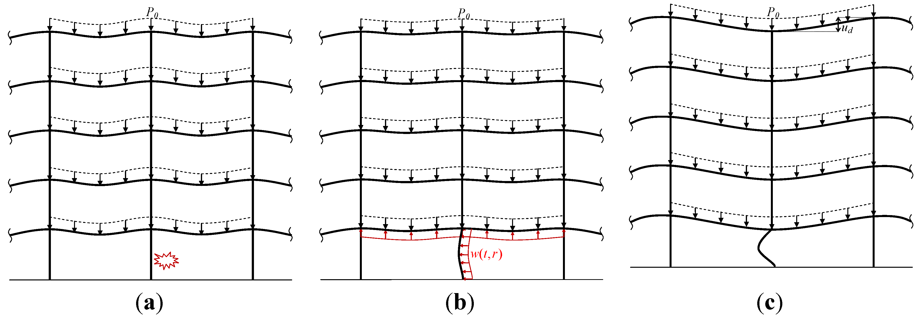
Figure 1, a planar model of a peripheral frame is used for simplification, with the primary objective of evaluating whether the damage to the first floor has a significant influence on the subsequent overall structural response. In reality, the blast damage to the affected column would be into the plane of the frame, though the assumption of planar column damage has a similar effect on the subsequent response of the floors above.
Figure 1 depicts schematically the response of the affected bay with a uniform total gravity load of
P0 under the considered localized blast loading. In this respect, the robustness limit state is defined as the avoidance of failure in the floors above the affected zone, where the
maximum dynamic response shown in
Figure 1c defines demands in the various connections which should remain within their respective ductility supply in order to avoid progressive collapse. Accordingly, the maximum dynamic response in the floors above can be used as a basis for the comparison of the actual localized blast condition with the idealized sudden column loss scenario.
Figure 1.
Bay of a multi-story building affected by blast. (a) Initial deformed shape (t =t0); (b) Intermediate stage (t0 < td < tf); (c) Maximum dynamic response (t =tf).
Figure 1.
Bay of a multi-story building affected by blast. (a) Initial deformed shape (t =t0); (b) Intermediate stage (t0 < td < tf); (c) Maximum dynamic response (t =tf).
2.2. Sudden Column Loss Scenario
The sudden column loss is identified by several design guidelines [
1,
2,
3,
4] as a suitable event-independent scenario for robustness assessment of building structures under localized damage. This event-independent scenario is of great advantage, since the robustness assessment of building structures can be studied without requiring detailed information on the extreme event. Furthermore, the sudden column loss scenario is typically associated with a dominant deformation mode, which allows the maximum dynamic response to be determined from the nonlinear static response [
6,
7] without the need for nonlinear dynamic analysis, as discussed in
Section 3.
As shown in
Figure 2, sudden column loss is considered to be instantaneous (
Figure 2a), where the maximum dynamic deformed configuration of the above floors is required (
Figure 2b). The maximum dynamic response defines the ductility demand in the floor system components, and the availability of ductility supply in the associated components determines the robustness of the structure against disproportionate collapse.
Figure 2.
Multi-story building under column loss. (a) Initial deformed shape (t =t0); (b)Maximum dynamic response (t =tf).
Figure 2.
Multi-story building under column loss. (a) Initial deformed shape (t =t0); (b)Maximum dynamic response (t =tf).
2.3. Comparison between Sudden Column Loss and Localized Blast
Bearing in mind the benefits of sudden column loss as a principal design scenario for assessing structural robustness, its resemblance to realistic localized blast events is studied here for a typical 5-story steel composite framed structure. All stories are 3 m high except the ground floor, which has a height of 5 m. A peripheral frame is considered to compare the effects of sudden column loss and localized blast loading, where typical UC305 × 305 × 198 are used for the columns, and UB457 × 152 × 52 are used for the beams in steel grade S355.
For structural modeling, nonlinear time-history analysis solution procedure is considered with cubic elasto-plastic beam elements and consistent mass matrix to capture the dynamic response of steel members and concrete slab. To account for full composite action, rigid shear transfers are considered via links interconnecting the beam elements to the centroid of the concrete flange. The concrete flange of the composite floor slab is 135 mm thick, but only the concrete above the top of the ribs of the composite decking profile is taken into account, which is 80 mm. The effective width concept is used for modeling the concrete slab [
15] and assuming a constant value of 0.8 m width for the whole length of the beam for simplicity. Furthermore, horizontal elasto-plastic springs with initial planar and rotational stiffness of 200
MN/mm and 30
MN.mm
/mm, respectively, are utilized at the boundary of the modeled frame to represent the lateral stiffness of the surrounding structure, as shown in
Figure 3a.
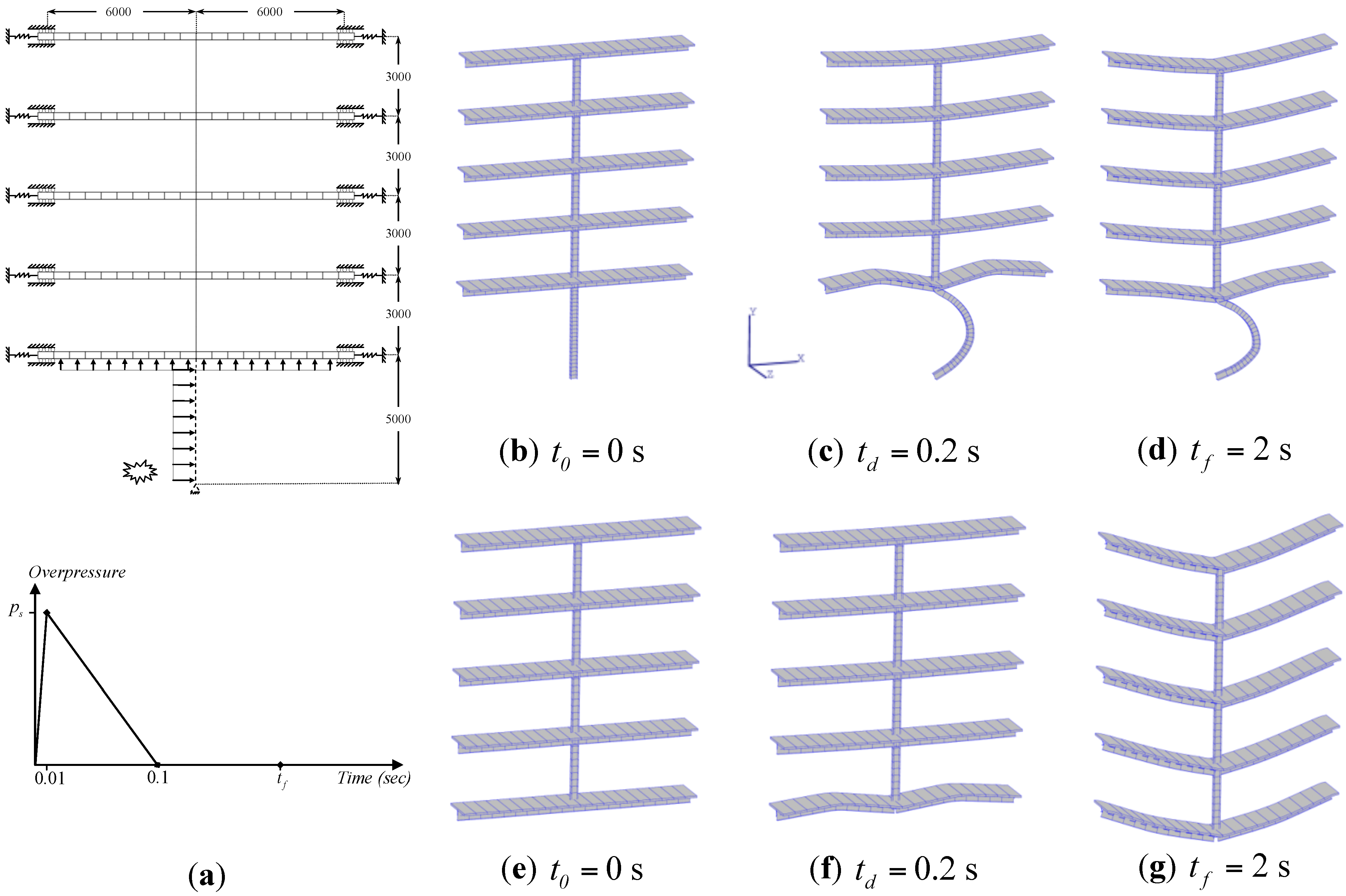
In modeling the localized blast loading, and based on tributary overpressure areas affecting the column and composite beams, uniformly distributed blast loads are applied to the column and first floor beams over a short duration of 0.1 s (
Figure 3a), where the distributed load on the column is about 0.15 of the distributed uplift blast load on the floor beams. The blast peak overpressure (
ps) on the column and floor above is obtained [
16] assuming that the blast is due to a charge located at a distance of 1 m and 5 m from the column and floor above, respectively. Nonlinear dynamic analyses are carried out for different ratios (
UBF) of peak uplift blast load on the first floor beams over the distributed gravity load, so as to establish the importance of uplift force on the structural response and the ductility demand for robustness assessment.
Figure 3.
Multi-story building under localized blast. (a) Structural configuration (dimensions in mm); (b–d) FE time history response for blasted column for UBF =10; (e–g) FE time history response assuming brittle shear failure of the column for UBF = 10.
Figure 3.
Multi-story building under localized blast. (a) Structural configuration (dimensions in mm); (b–d) FE time history response for blasted column for UBF =10; (e–g) FE time history response assuming brittle shear failure of the column for UBF = 10.
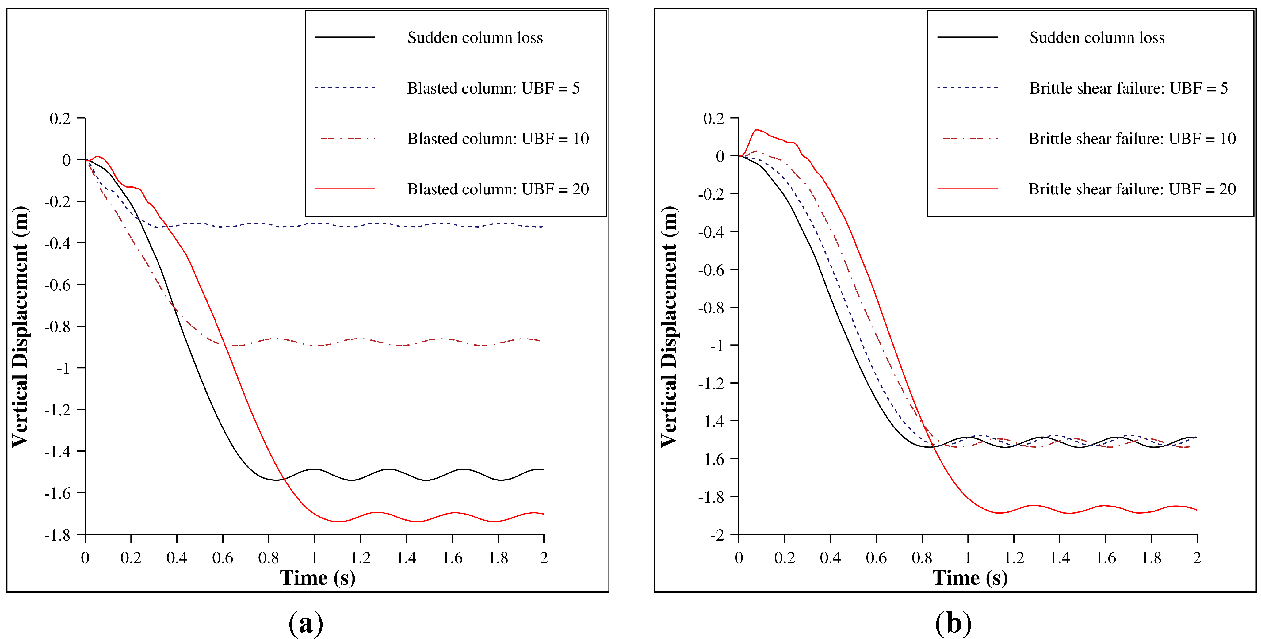
Figure 4a compares the maximum dynamic vertical displacement of the frame under extreme blast loading with
UBF values equal to 5, 10 and 20 against the response obtained with sudden column loss. It is shown that sudden column loss provides an upper bound on the maximum dynamic deformations from localized blast damage for
UBF values of 5 and 10, providing comparable results for
UBF of 20. The deformed configuration of the frame for the cases of blasted column and brittle shear failure under
UBF of 10 is shown in
Figure 3b–d and
Figure 3e–g for the initial, intermediate and maximum dynamic displacement stages, respectively.
Similar analyses are carried out for more critical cases where the affected column experiences brittle shear failure under the localized blast. In these cases, illustrated in
Figure 3e–g, the comparison with sudden column loss in
Figure 4b shows that the effect of uplift pressure on the maximum dynamic response is negligible for uplift blast factors below 10. However, the effect of uplift becomes of some significance as the uplift pressure increases substantially relative to the floor system weight. Based on these analyses, it is concluded that sudden column loss can still be considered as a conservative scenario for robustness assessment of multi-story buildings, even under localized blast events that affect a column and the surrounding floor system.
Figure 4.
Comparison between sudden column loss and extreme internal blast.(a)Considering the residual strength of the blasted column; (b) Assuming brittle shear failure of the column.
Figure 4.
Comparison between sudden column loss and extreme internal blast.(a)Considering the residual strength of the blasted column; (b) Assuming brittle shear failure of the column.
3. Multi-Level Framework Developed at Imperial College
A multi-level framework has been recently developed at Imperial College London [
5] for progressive collapse assessment of multi-story building structures under sudden column loss scenarios. The approach provides a useful and practical mean to measure structural robustness based on the system maximum dynamic response (so called
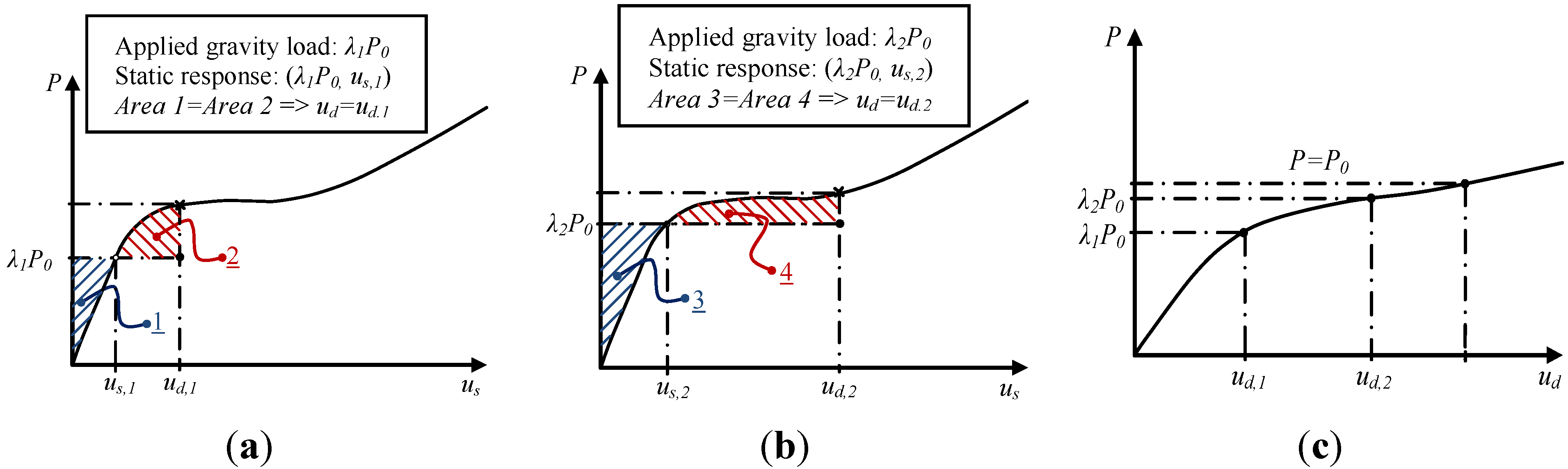
“pseudo-static response”), which accounts for ductility, redundancy, energy absorption capacity and the dynamic nature during sudden column loss event. Towards this end, the quantification of the pseudo-static capacity is achieved through three main stages, including determination of the nonlinear static response, dynamic assessment using the principle of energy balance, and ductility assessment.
In the first stage, the nonlinear push-down static response of the structure under column removal is established. This can be effectively obtained through simulation of the structure under the application of gravity loading (
P0) and in the absence of the damaged column. Carrying out the analysis with incrementally increasing the applied gravity load (Δ
λ.P0) (
i.e., load control) or the vertical displacement at column loss (Δ
us) (
i.e., displacement control) the nonlinear static response under column loss can be established in terms of the applied gravity load
vs. the maximum vertical displacement (
λiP0-us,i), as illustrated in
Figure 5a.
The sudden nature of column damage in extreme events, leads to considerable inertia forces in the system. Therefore, it is necessary to account for these dynamic effects under such a scenario, and ductility assessment should in principle be considered for all deformation states up to the maximum dynamic response. Although nonlinear dynamic analysis offers the most accurate way to obtain the maximum dynamic response, this type of analysis is computationally intensive. To avoid this computational demand, the nonlinear static response can be transformed to the maximum dynamic response (
λiP0-ud,i), or pseudo-static response, using energy balance principles [
5]. The simplified dynamic assessment assumes a dominant deformation mode following column loss scenarios, where the maximum dynamic displacement occurs when the kinetic energy, initially increasing due to the applied gravity load exceeding the static resistance, reduces back to zero after the load becomes less than the static resistance. Using the principle of energy balance, the maximum dynamic displacement (
ud,i) can be obtained for a specific level of applied loading (
λiP0) through a simple transformation of the nonlinear static response (
λiP0-us,i), which equates the external work done by the load to the internal absorbed energy, as illustrated graphically in
Figure 5.
This simplified dynamic assessment approach provides for a specific level of gravity loading the maximum dynamic displacement, which is then related to connection deformation demands based on the structural deformation mode [
5]. Comparing these demands to the ductility capacity in different structural and connection components up to the maximum dynamic displacement defines whether the robustness limit state is exceeded and, hence, whether progressive collapse is likely to be initiated.
Figure 5.
Static (
λiP0-us,i) and pseudo-static (
λiP0-ud,i) response. (
a) Maximum dynamic response at (
λ1P0-ud,1); (
b) Maximum dynamic response at (
λ2P0-ud,2); (
c) Complete pseudo-static response. [
5].
Figure 5.
Static (
λiP0-us,i) and pseudo-static (
λiP0-ud,i) response. (
a) Maximum dynamic response at (
λ1P0-ud,1); (
b) Maximum dynamic response at (
λ2P0-ud,2); (
c) Complete pseudo-static response. [
5].
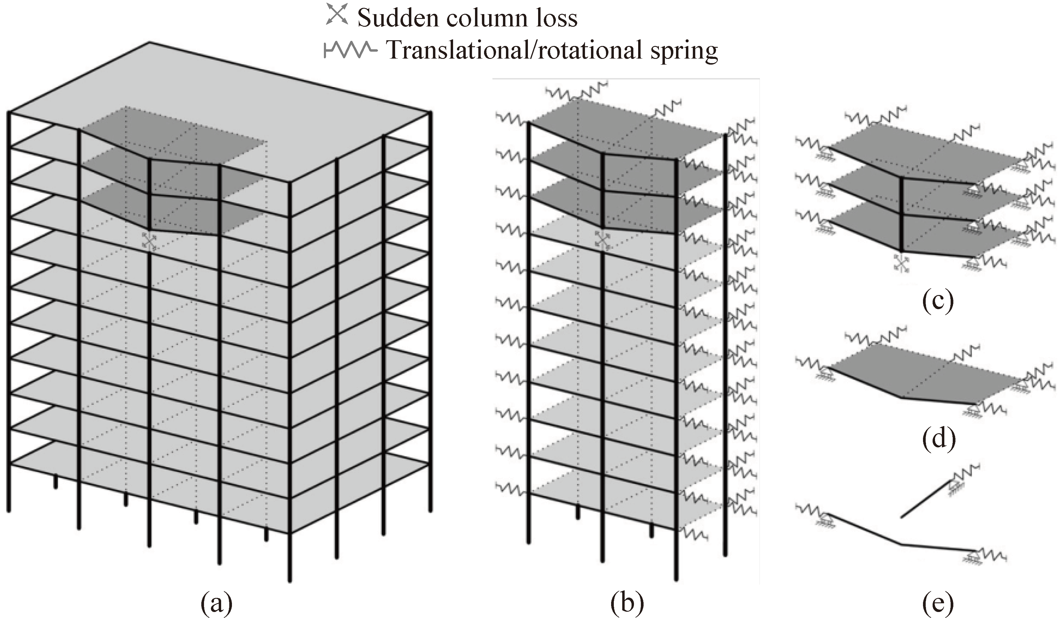
It is important to note that the assessment framework discussed above can be applied at various levels of structural idealisations depending on the feasibility of model reduction and the desired level of sophistication. The structural idealisation of a multi-story building under a column loss could be considered from highest to the lowest as: (i) full building (
Figure 6a); (ii) affected frame (
Figure 6b); (iii) multiple floors (
Figure 6c); (iv) individual panel zone floor (
Figure 6d); and (v) individual beam level (
Figure 6e). In the remainder of this paper, focus is given to the individual floor level of idealization, which is realistic for buildings in which the floors above the affected column (
Figure 6b–c) are identical in terms of structure, gravity load and boundary conditions.
Figure 6.
Structural idealization levels for column loss scenarios [
5].
Figure 6.
Structural idealization levels for column loss scenarios [
5].
4. Floor Level
As highlighted above, assuming similar loading and structural configuration at different floor levels, the robustness assessment of building structures can be carried out at the individual floor level. Some of the past research in this field considered the capacity of bare steel frame floor systems with moment-resisting connections and simple connections [
6,
17,
18]. In this respect, it is established that the load transfer mechanism for bare steel systems is dominated at the early stages of the response by the flexural behaviour. Subsequently under large deflections, tensile catenary action becomes activated in the presence of sufficient lateral restraint. This is illustrated later in
Section 6.3.1 for a floor system with edge restraint.
More recently, the key role of membrane action in reinforced concrete (RC) floor slabs towards mitigating the effects of column loss has been identified [
6,
7,
10,
11,
12]. Under conventional design loading conditions, flexural action is the primary source of load resistance; however, as vertical deflections increase, the primary load resistance mechanism of the slab transitions to tensile membrane forces in the plane of the slab. For slabs under internal column removal, the in-plane forces can be equilibrated either by surrounding edge restraint (
Figure 7a) or via a self-equilibrating compressive ring formed around the tension zone (
Figure 7b). Based on this, it is apparent that for a slab with fully clamped edges, bending and compressive arching action can significantly increase the slab load carrying capacity at small deflections. As the deflections increase, a larger tension zone will be formed in the slab compared to the unrestrained case, which can distribute the tensile force carried by the slab reinforcements more efficiently.
Figure 7.
Membrane actions in RC slabs. (a) Clamped; (b) Unrestrained.
Figure 7.
Membrane actions in RC slabs. (a) Clamped; (b) Unrestrained.
For steel-decked composite floor systems, the load transfer mechanism is much more complicated due to the interactions between the composite slab and the steel beams via the shear studs. To add further complexity to the problem, the steel decking system in corrugated slabs transfers the tensile load only along the direction of the ribs because of its trapezoidal shape. The majority of research and experimental work [
19,
20] so far have focused on characterizing the response of the individual components used in corrugated slabs.
More recently, new studies have considered numerical analyses of full composite floor slabs under internal [
11,
12] and peripheral [
7] column loss scenarios, investigating the key parameters influencing the floor system resistance such as reinforcement ratio, steel decking, and others. While these studies confirmed the significant enhancement in the resistance of composite floor systems through in-plane membrane forces in the slab, the lack of full experimental results for model validation raises questions on whether typical composite floor systems provide sufficient enhancement in the structural resistance to prevent progressive collapse under sudden column loss. Therefore, a collaborative experimental and numerical program is undertaken in this work so as to validate the numerical models for subsequent use in parametric studies aimed at improved design guidance.
5. Experimental Testing Program
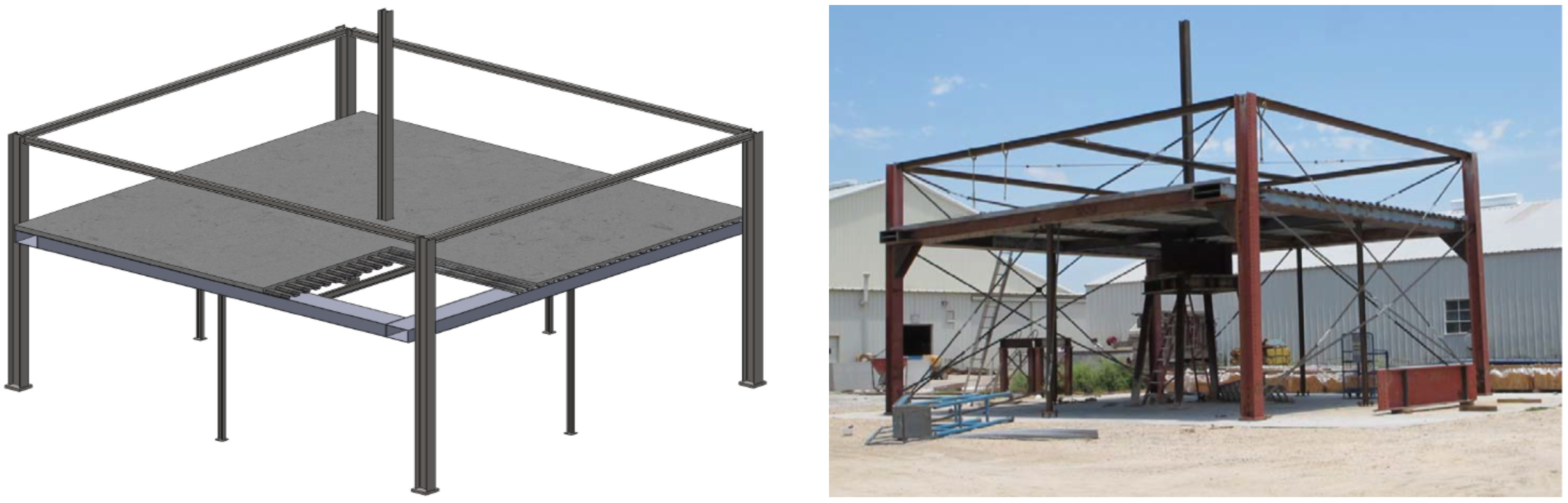
The purpose of the experimental testing program is to investigate the response and to quantify the performance of composite steel-concrete floor slabs that undergo large deformations associated with a column removal scenario. As described previously, past research has shown that there are various components in such floor systems that contribute considerable resistance in mitigating collapse. For the current study, a 2-bay × 2-bay section of a typical steel framed building with composite floors is subjected to an interior static column loss scenario as shown in
Figure 8. The effects of sudden column loss would then be considered using the simplified dynamic assessment approach discussed in
Section 3.
Figure 8.
Test specimen setup.
Figure 8.
Test specimen setup.
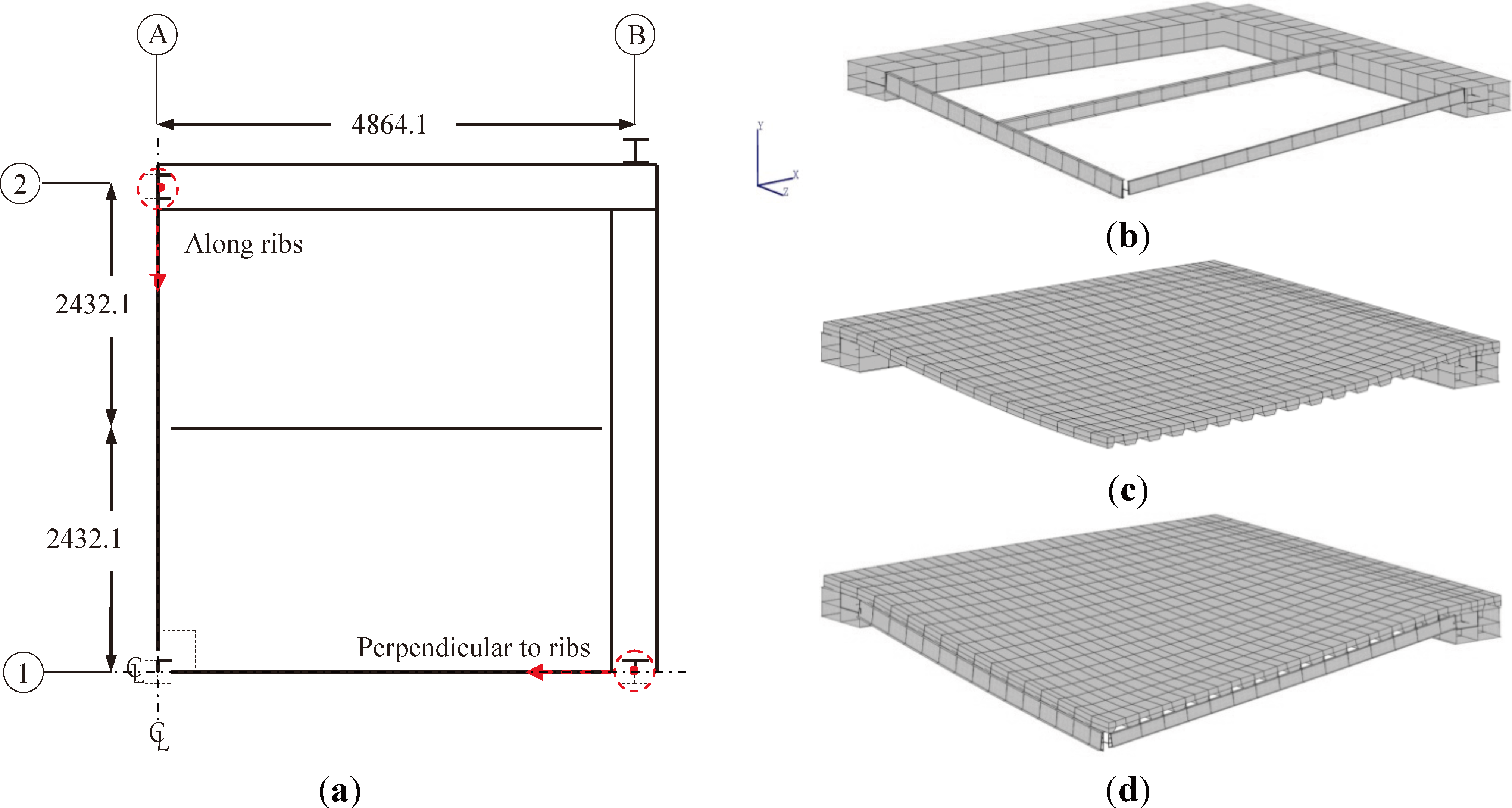
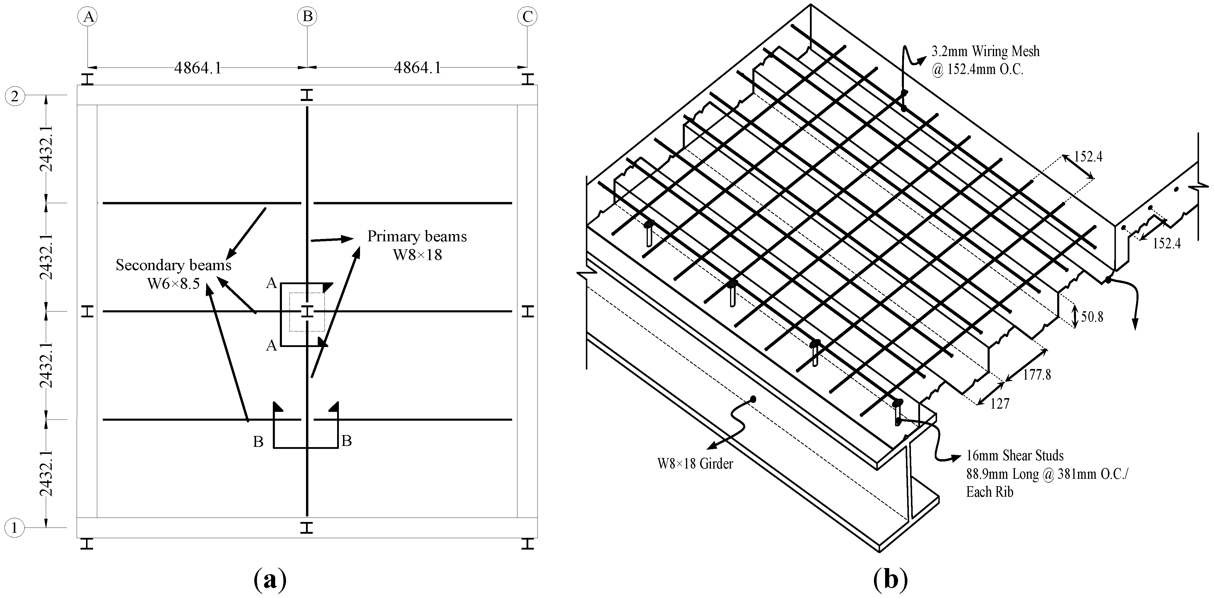
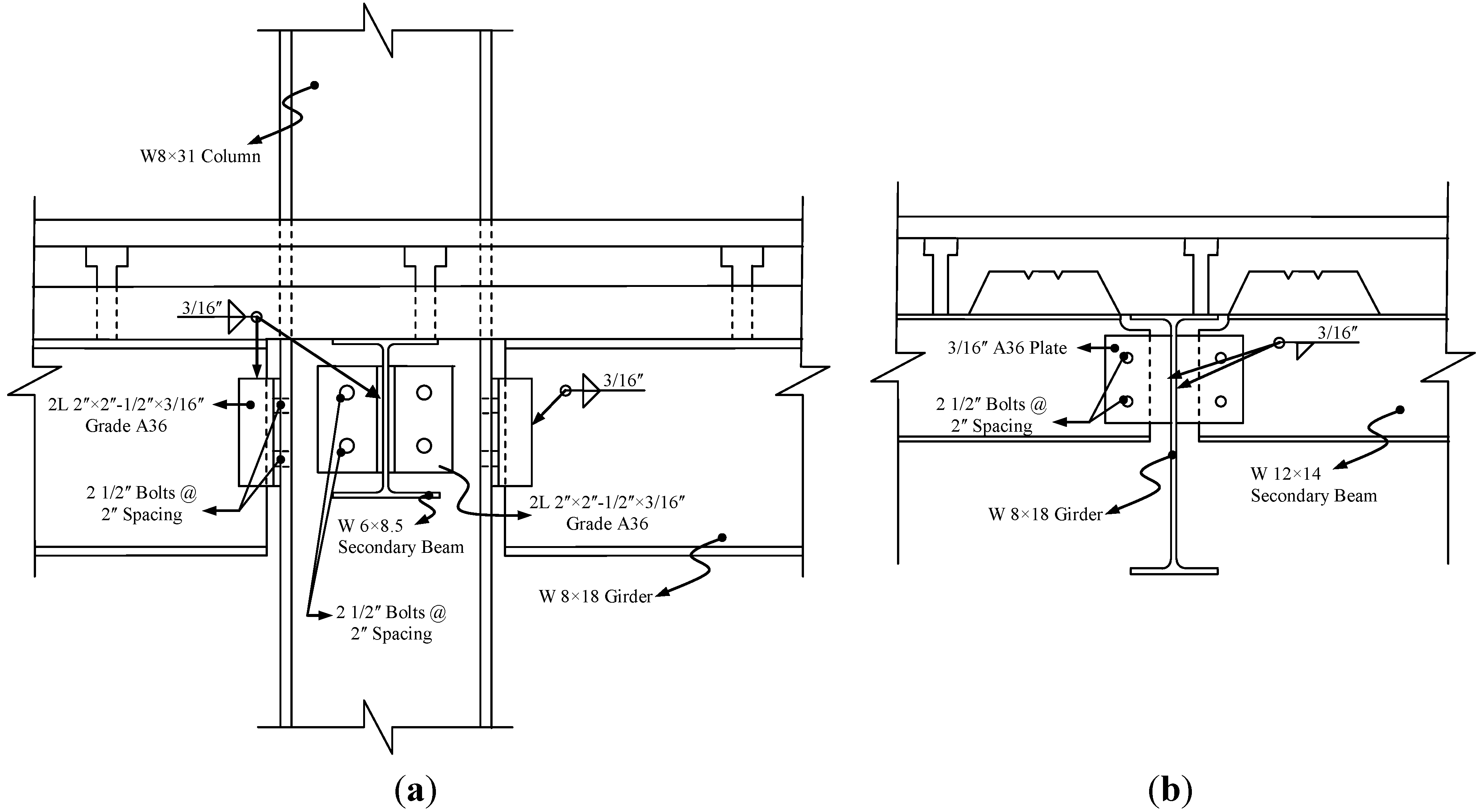
5.1. Description of Building Prototype
The test specimen (
Figure 8) consists of an isolated section of a typical small-span compositely constructed building. The building is a steel framed structure that uses simple connections (
i.e., double angle and shear tab connections). A concrete floor slab is poured over corrugated steel decking, which is intended to work compositely with the steel beams and girders through shear studs. Using a prototype building, the specimen was designed to be consistent with common practice. The design loads, connection types, and construction details match those found in conventionally constructed buildings (
i.e., the specimen includes no special design features to mitigate progressive collapse). For economic reasons, the spans of the investigated floor slab are smaller than those encountered in most commercial buildings, but the members and connection strengths have been sized accordingly to resist the design loads. To simulate the lateral restraint that would be provided by the surrounding bays of the prototype building, a relatively stiff restraining beam has been designed that circumscribes the test specimen and enables the activation of in-plane membrane action in the system.
5.2. Description of Test Setup
A series of tests is currently underway at Ferguson Structural Engineering Laboratory at The University of Texas at Austin to investigate the response of composite steel-concrete floor systems under a column removal scenario. The first test for the interior 2-bay × 2-bay section of the prototype building has already been completed. Additional tests are planned for scenarios involving the removal of a perimeter column. The test frame has been designed to accommodate both interior 2-bay × 2-bay and exterior 2-bay × 1-bay sections of the prototype building. A hydraulic actuator is placed at the position of the column that is assumed to fail to simulate a column removal scenario.
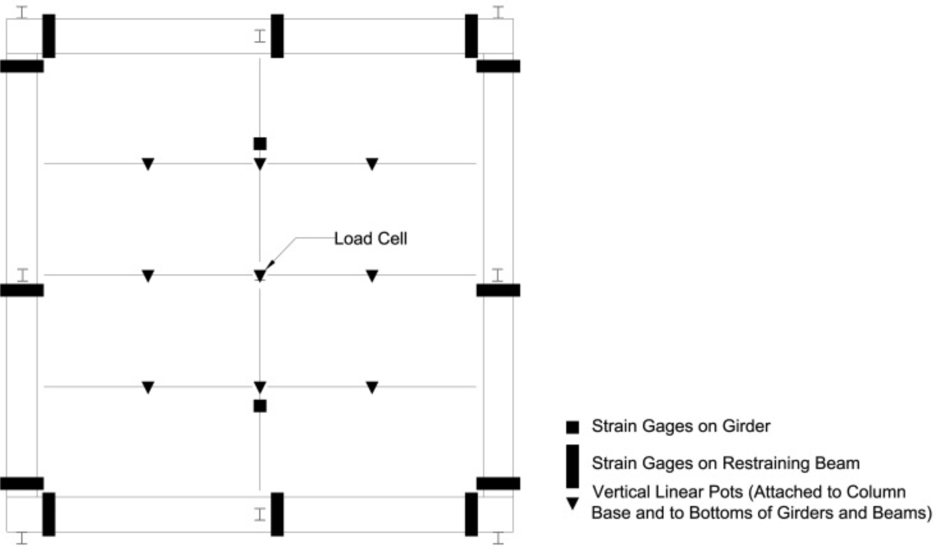
Figure 9 shows the instrumentation plan for the first test. A load cell captures the reaction at the “failed” column while horizontal linear potentiometers (not shown in
Figure 9) measure the relative displacement between the girder-to-column and beam-to-column connections. Vertical linear potentiometers are positioned to capture the vertical displacements over the entire area of the floor slab. During testing, the actuator gradually lowers until it no longer supports any load. Strain gages are placed at midspan of the two primary beams to monitor changes in the strain profile over the section depth during the removal of the column. Strain gauges are also placed on the restraining beam at twelve different positions: the four corners and the middle of each of the four edges. The aim of these gauges is to capture the in-plane forces that would potentially develop in the restraining beam due to the catenary response of the floor slab under large displacements.
The first series of tests for both the interior and exterior portions of the prototype buildings are based on common design practice without any progressive collapse provisions. Results from the initial tests will be used to identify critical system components, and subsequent specimens will include design modifications that are intended to enhance structural robustness.
Figure 9.
Test specimen instrumentation plan.
Figure 9.
Test specimen instrumentation plan.
5.3. Test Procedure
To simulate an internal column loss scenario, the slab is initially supported at the center of the test specimen, and a distributed load consistent with the UFC [
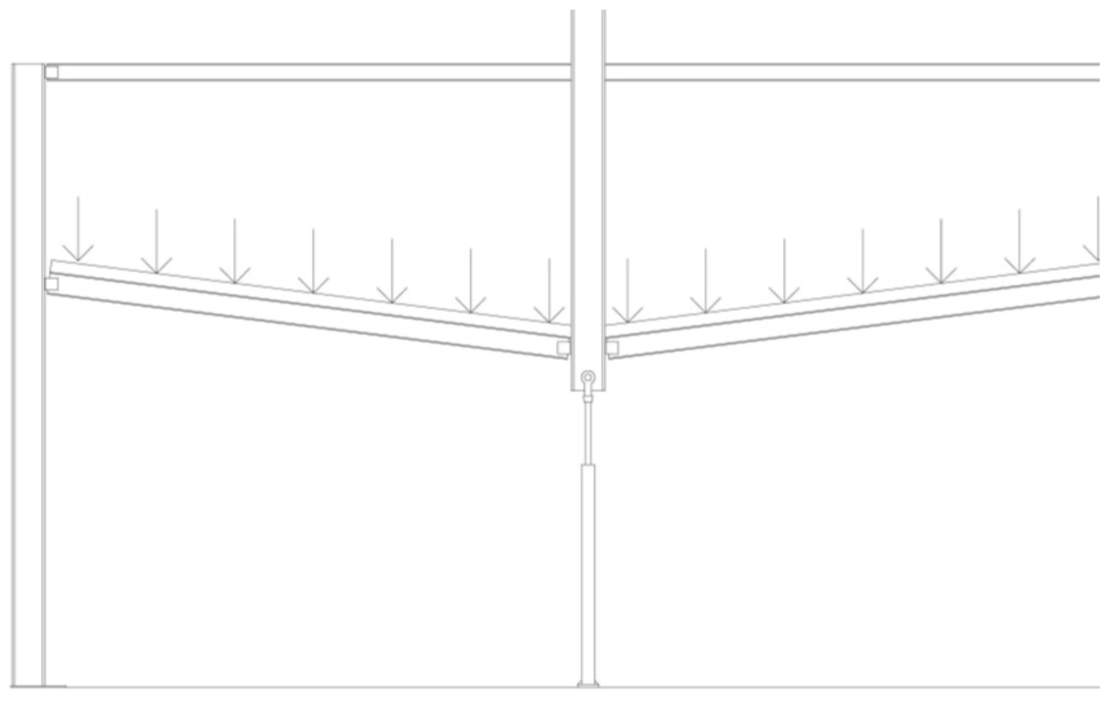
3] recommended collapse design load is imposed on the structure. The center column is then removed slowly (
i.e., statically) by means of a hydraulic actuator supporting the floor slab, allowing the floor slab to displace downward (
Figure 10) under some levels of self-gravity load. After the force in the hydraulic actuator becomes zero, in other words when the slab is supporting the entire self-weight gravity load, buckets positioned on the slab are filled with water to add further distributed load on the system.
The main advantage to the proposed static testing procedure is that the slow unloading rate will allow detailed study of the floor slab response as the displacements become large and as the membrane response develops in the slab. Furthermore, identifying the floor system response under static column removal provides an invaluable knowledge regarding the floor system characteristics to validate the detailed numerical models. The accurate static load-deflection curves obtained from the test and validated numerical analyses are then used for assessing the ductility limits and dynamic response using the energy based approach.
Figure 10.
Lowering of central column to simulate column loss.
Figure 10.
Lowering of central column to simulate column loss.
The actuator representing the column allows for a central displacement of 2.2 m (approximately 23% of the doubled span length), a deflection that is significantly larger than the predicted failure displacement (described later in the paper). Thus, the test setup allows the floor slab to reach its full displacement capacity. The test setup permits additional load to be applied in the event that the specimen withstands the column removal scenario without failing. In the first test, the specimen was able to resist the static column removal and the total superimposed load placed on the floor slab after the central column was lowered. The total load applied exceeded the extreme event design load prescribed in the UFC [
3] by a factor of approximately 1.6. Because of this excellent performance, modifications to the test setup and specimen design are being evaluated so that floor system performance under large deformations can be measured in subsequent tests.
7. Conclusions
In this paper, a comprehensive research program to assess the robustness of compositely constructed steel-framed buildings is presented. The work focuses on the response of typical composite floor systems subject to sudden column loss, which is shown in this paper to be a conservative damage scenario compared to more realistic localized blast damage involving not only the column but also the surrounding floor system.
The research program includes detailed computational modeling and large-scale testing of a prototypical floor system. To date, testing has been completed for an interior column loss scenario, and the results indicate that the floor system has substantial capacity to resist the design loads. The test structure was able to resist statically an applied load that is approximately 1.6 times greater than the prescribed progressive collapse design load without sustaining any significant damage. The floor system is also shown to withstand the sudden loss of the column allowing for dynamic amplification of about 1.6 obtained from simplified nonlinear dynamic assessment. Predictions of response made using the computational models developed during this study show good agreement with the collected test data.
In the next series of tests, the test setup will be modified to allow the floor system to experience more significant damage so that ductility limits can be determined and so that the contributions of different floor system components can be assessed. In addition, perimeter column loss scenarios will be a focus of future testing and computational simulations. Results from this research will provide valuable data regarding the robustness of compositely constructed floor systems and provide an understanding of their performance in potential collapse scenarios. Furthermore, the test data will give the ability to validate numerical models used to predict the behaviour of such floor systems, which will allow project researchers to make recommendations on modeling techniques needed to accurately assess structural robustness. With such information, engineers can gain confidence in predicting the response of composite steel structures subjected to column loss scenarios.


