1. Introduction
In 2008, Wiss, Janney, Elstner Associates, Inc. (WJE) was contacted by the Town of Avon, Colorado to investigate deterioration of the exterior concrete masonry unit (CMU) facade of the Avon Recreation Center. The 32,500 ft
2 (3,252 m
2) building is one and a half stories plus a partial basement housing the mechanical systems. Spaces include a 14,800 ft
2 (1,375 m
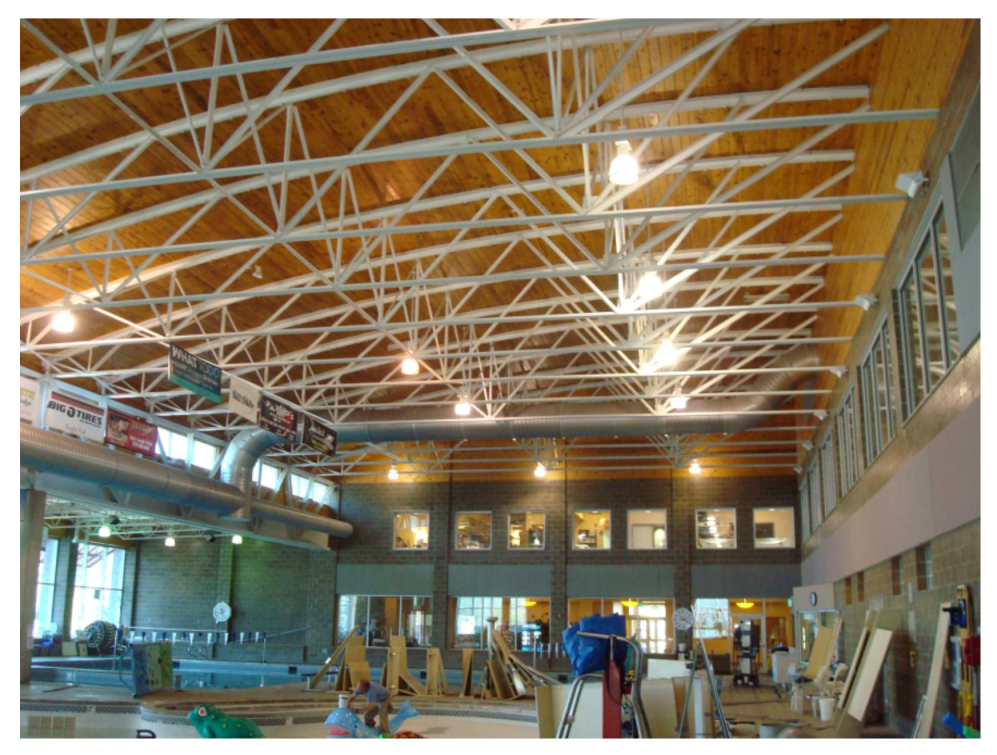
2) natatorium with a lap pool and two leisure pools, locker rooms, aerobics and weight rooms, child care, and offices. The majority of the exterior façade is clad with either single wythe CMU or exterior insulation and finish system (EIFS). The interior walls of the natatorium are CMU with wood tongue and groove siding at the upper walls, and three-inch tongue and groove wood roof decking supported by exposed steel trusses (
Figure 1). The natatorium is conditioned with a dedicated air handling unit (AHU) and exhaust system with energy recovery; there is no mechanical cooling. The building was constructed in 1995: about 13 years prior to the investigation. Visible deterioration of the exterior façade that concerned the owner and caused him to initiate the investigation included efflorescence, spalling, blistering, and erosion of the faces of the exterior CMU. The investigators were tasked with determining the cause of the deterioration, and developing a scope for repairs. The investigation and repairs took place beginning in 2008, and were completed in 2010.
Figure 1.
Interior of natatorium.
Figure 1.
Interior of natatorium.
Avon, Colorado is located in the Rocky Mountains in Eagle County, at an elevation of 7,431 feet (2,265 m) above sea level. The closest weather station is the Eagle County airport, located at 6,535 feet (1,992 m) elevation. This station has an American Society of Heating, Refrigeration, and Air Conditioning Engineers (ASHRAE) 99.6% heating design temperature of −8.3 °F (−22.4 °C), and a 1% cooling design temperature of 85.3 °F (29.6 °C) with a mean coincident wet bulb of 56.8 °F (13.8 °C) [
1]. The climate is cold throughout the winter, cool in the summer and swing seasons, and quite dry all year-round.
2. Background
The ASHRAE recommended indoor design conditions for a natatorium are 85 °F (29.4 °C), which is 2 to 4 °F (about 1 to 2 °C) warmer than the pool water temperature, and 50% relative humidity (RH). At these conditions, the air contains a large amount of moisture that will condense on surfaces that are at or below the dew point temperature of the air. At 85 °F (29.4 °C), 50% RH, and 6,535 feet (1,992 m) elevation, the dew point is just over 65 °F (18.3 °C). This means that water will condense out of the air if the air comes in contact with surfaces that are 65 °F (18.3 °C) or colder. In order to protect high risk materials, the moist interior air must be contained within the natatorium space by a continuous interior air and vapor barrier, or sensitive materials must be kept warmer than 65 °F (18.3 °C). Providing an air barrier at interior walls also serves to prevent humid air from migrating into the rest of the building.
Since it is difficult to create a completely tight air barrier, ASHRAE recommends that the heating, ventilating, and air conditioning (HVAC) system in a natatorium be designed to maintain a negative pressure in the space relative to the outside [
2]. If the natatorium is kept negative, any discontinuities in the air barrier will let dry outside air into the space, rather than push moist interior air into the exterior wall and roof constructions. Maintaining a negative pressurization is most critical when the outdoor temperatures are lowest in the winter, since the enclosure materials are most likely to be at or near the dewpoint temperature at this time.
Since the warm humid interior air has a lower density than the cold dry outside air, the interior air has a buoyancy force that exerts a positive pressure above mid height of the interior spaces (the neutral pressure plane of the building) when the outside air temperature is lower than the interior air. This “stack effect” pressure is greatest at the top of the space where the roof meets the wall. This location also typically presents a difficult condition for maintaining the continuity of the air barrier because of structural bracing and connections between the roof and wall systems.
The HVAC system must overcome both the stack effect pressure and leakage through the enclosure to keep the entire space at a negative pressure. The lack of a continuous interior air barrier coupled with an HVAC system that fails to maintain a negative pressurization are common system failures that can lead to serious and expensive problems in spaces with humid interior air such as natatoriums. This case study highlights specific failures and repair efforts undertaken in one such building in Colorado.
3. Investigation
3.1. Exterior Walls
To begin the investigation, the investigators performed a review of construction documents along with a visible inspection of the building that included architectural and mechanical systems. Spalling, efflorescence, and blistering of the masonry was observed throughout the façade (
Figure 2a), with the most severely deteriorated masonry at the southwest corner below the soffit. Ice was found forming on the façade in some locations (
Figure 2b). When the soffit was examined, a pool chemical odor was detected at the soffit vents, indicating that interior air was exfiltrating out through the grilles. This revealed that pool room was likely positively pressurized relative to the exterior at this location. There was no visual evidence of distress on the interior side of the exterior walls.
From these initial inspections, the investigators concluded that the deterioration at the exterior CMU walls was a result of moisture laden air from the interior being forced into the wall assembly by a positive pressurization of the natatorium. Based on the locations of most of the CMU deterioration, a breach in the air barrier at the intersection of the wall and roof was the likely path for the moist interior air to travel into the wall. Further, the wall assembly was not able to properly dry to the outside due to a coating that had been applied to the exterior face of the CMU. The moisture trapped in the wall froze at night and thawed out during the day, causing freeze-thaw deterioration. The large daily temperature swings of the dry mountain climate amplified this effect.
Figure 2.
(a) Blistering and spalling at south façade; (b) Ice formations.
Figure 2.
(a) Blistering and spalling at south façade; (b) Ice formations.
The architectural drawings specified a 6 mil polyethylene vapor barrier to be installed within the wall assembly and continue up to the underside of the three-inch tongue and groove wood roof deck, but a seal to the roof air/vapor barrier was not detailed. The wall vapor barrier also functions as an air barrier, which is its more critical function in this building. If the wall air/vapor barrier is not properly sealed to the roof air/vapor barrier, an avenue for air migration is created.
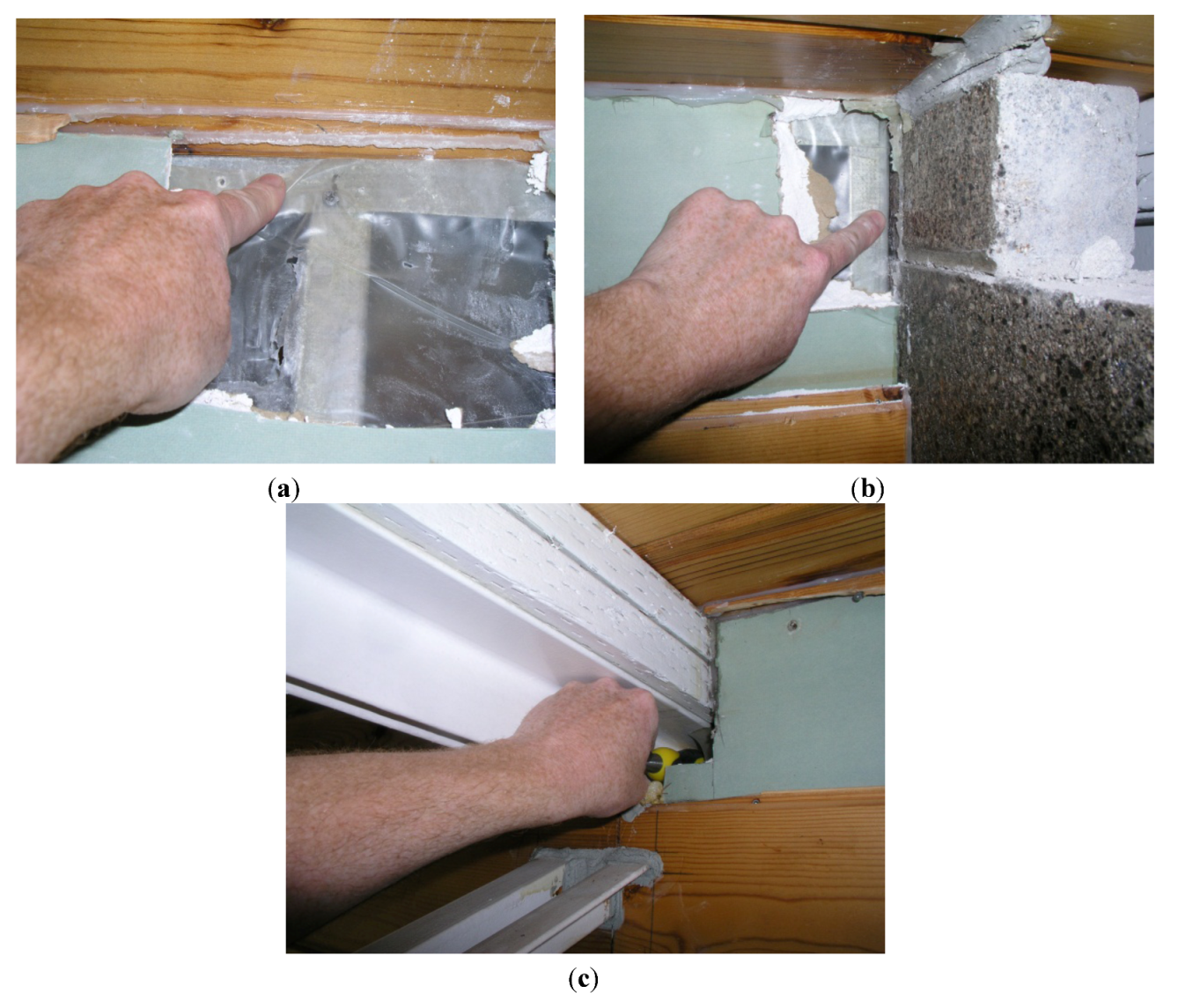
The investigators made three investigative openings at the interior face of the exterior wall where it meets the roof deck. The openings were primarily meant to determine how the air barrier was terminated at the roof, and to determine as-built conditions in order to develop repair details to improve the continuity of the air/vapor barrier. In opening the walls, the investigators found a number of concerns: (1) the air/vapor barrier at the top of the wall was not sealed to the roof air/vapor barrier or the decking (
Figure 3a); (2) the air/vapor barrier at the wall sheathing to CMU pier interface was not sealed at penetrations of the roof trusses (
Figure 3b); (3) there were significant gaps in the air/vapor barrier where the roof truss top chords penetrate the CMU piers and exterior wall (
Figure 3c); (4) there was no air/ vapor barrier in some areas adjacent to windows; and (5) there was no air/vapor barrier at interior walls separating the natatorium from mechanical spaces.
Figure 3.
(a) Air/vapor barrier at wall to roof interface; (b) Air/vapor barrier at concrete masonry unit (CMU) pier; (c) Gap in wall at truss penetration.
Figure 3.
(a) Air/vapor barrier at wall to roof interface; (b) Air/vapor barrier at concrete masonry unit (CMU) pier; (c) Gap in wall at truss penetration.
These breaches in the air/vapor barrier correlated with the observed distress on the exterior CMU walls, and supported the theory that this was the path of moisture laden air penetrating the building envelope. Proper termination of the wall air/vapor barrier to the roof deck, along with sealing the open gaps at the truss penetrations, should significantly reduce the amount of interior air that can enter the exterior wall construction. Termination of the wall air/vapor barrier to the roof air/vapor barrier, although the preferred remedy, was cost-prohibitive.
3.2. Roof
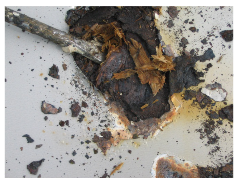
About a year after the initial investigations (the schedule was dictated by the owner’s financing availability), the investigators performed inspections of the natatorium metal panel roof that revealed components saturated with moisture and significant deterioration (
Figure 4). The original roof consisted of, from outside to inside: architectural metal panel roofing system on an oriented strand board (OSB) surface board, composite insulation, self-adhered membrane (air/vapor barrier) on plywood sheathing, and a tongue and groove wood deck. The investigators learned from maintenance personnel that roof leaks had been an ongoing problem throughout the life of the building, especially at the natatorium. In the past few years corrosion had become visible on the metal panels of the roof over this space.
Figure 4.
Deterioration of oriented strand board (OSB) at roof.
Figure 4.
Deterioration of oriented strand board (OSB) at roof.
As with the deterioration of the façade, these issues were initially suspected to be in part the result of a moisture drive from the interior of the building into the exterior enclosure. However, the investigators found that the moisture in the roof was primarily a result of water leaking in from the outside. The inspection of the roof over the natatorium revealed that corrosion of the metal panels was occurring throughout the entire roof area, with the highest concentration of corrosion occurring at the area of lowest slope: flat to one-half inch slope per foot. The metal panel roofing was an architectural metal panel system, which is designed to shed water. This type of system is not watertight, and to function properly should be installed with a minimum slope of three inches per foot. The curved roof system had been installed flat at the top, allowing significant amounts of moisture from rain and snowmelt to enter into the system. The structural integrity of the roof wood decking had not yet been compromised, but was likely to be if repairs were not made.
3.3. Mechanical Systems
The natatorium is served by a constant volume AHU with natural-gas fired heating and no mechanical cooling. In this cool dry climate, an economizer uses outside air to provide cooling to the space and to control humidity levels. A roof mounted exhaust system with a variable frequency drive (VFD) was designed to control the pressurization in the space. The exhaust system has a run-around loop energy recovery system to move heat from the exhaust air stream to the supply air. At the time of the inspection, the exhaust fan was set to maintain a negative pressure of 0.5 inch WC (124.5 Pa) relative to the rest of the building, but there was no exterior pressure sensor. Outside air dampers were closed when they should have been letting in outside air for cooling and dehumidification. The indoor temperature and humidity sensors were found to be either out of calibration or broken. Due to the HVAC system’s state of disrepair, along with the lack of system design to maintain a negative pressure relative to the outside, the natatorium was at a positive pressure relative to the outside and relative to adjacent spaces in the building. This had likely been the case for quite some time.
Repairs to the building must include establishing a negative pressurization with the HVAC system. The HVAC system had been designed with sufficient exhaust capacity to provide the negative pressurization. However, controls had gone out of calibration since the systems were installed, in part because the maintenance staff did not fully understand the intent of the equipment. Recommended HVAC repairs were fairly straightforward and of low cost. They consisted of repairing or replacing sensors, providing an outside pressure sensor, and reprogramming the system to maintain a negative pressure of 0.01 inch WC (2.5 Pa) near the roof of the natatorium relative to the outside.
4. Recommendations and Repairs
As a result of these investigations, the investigators recommended:
Repairing the natatorium air/vapor barrier at the wall-to-roof interface and where trusses penetrate exterior and interior walls;
Re-balancing the mechanical system to provide a negative pressurization in the space;
Replacing deteriorated CMU units;
Removing the exterior coating on the face of the CMU;
Replacing the metal roof, insulation and air/vapor barrier at the natatorium as soon as possible.
The investigators provided construction documents for the repairs to the air/vapor barrier to seal gaps at truss penetrations with spray polyurethane foam, and to terminate the air/vapor barrier at the roof using a sealant and termination tape. Because of the low slope of the roof, recommendations included replacing the existing metal panel roof at the natatorium with a thermoplastic single-ply 80 mil PVC membrane system fully adhered to a gypsum cover board. The insulation and sheathing on top of the wood deck were also replaced, with a sheet waterproofing membrane installed on the sheathing board.
The City of Avon has implemented all of the recommended repairs other than removing the coating on the face of the CMU. They have been monitoring the building closely since the repairs, and there have been no signs of further deterioration. Providing better continuity in the air/vapor barrier and re-balancing the HVAC system were the critical repairs in remediating moisture migration into the enclosure from the inside.
5. Conclusions and Lessons Learned
This project is an example of an apparent architectural issue that was caused by a combination of architectural and mechanical system issues. The positive space pressurization that led to deterioration of the enclosure was a result of improper operation of the mechanical systems in conjunction with breaches in the exterior air/vapor barrier. The solution stemmed from an understanding of how the two systems must work together in a well-functioning natatorium. Key lessons that can be taken from this project include:
Providing a continuous interior air and vapor barrier in a natatorium, or in any space with high levels of interior humidity, is critical;
The HVAC design engineer must understand the importance of designing such spaces for negative pressurization relative to the outside, and properly design for such pressurization;
Maintenance personnel must understand the intent of the systems and be able to oversee that they continue to function as designed throughout the lifetime of the building.
