1. Introduction
The province of Kutahya, Turkey was shaken by a moderate earthquake on 19 May 2011. The epicenter was near Söğüt village, 13 km northeast of Simav, Kütahya. Two people died and 122 people were injured in the earthquake. Many people were out of their homes at the time of the earthquake because there was a 3.8 magnitude earthquake foreshock 16 min before the main shock. This resulted in less casualties and injuries during the main earthquake. The authors visited the district of Simav and nearby villages shortly after the earthquake and performed a thorough damage assessment.
The location of the epicenter, magnitude and focal depth of the earthquake were reported by several institutions following the earthquake. As summarized in
Table 1, the reported information, especially the focal depth, varied.
Table 1.
Simav earthquake information reported by different institutions.
Table 1.
Simav earthquake information reported by different institutions.
| Source | Location | Depth (km) | M |
|---|
| KOERIa [1] | 39.152° N, 29.088° E | 8.0 | 5.9 |
| USGSb [2] | 39.137° N, 29.074° E | 9.1 | 5.8 |
| AFADc [3] | 39.133° N, 29.082° E | 24.46 | 5.7 |
| EMSCd [4] | 39.150° N, 29.100° E | 7.0 | 5.8 |
Although this was a medium intensity earthquake, three aspects of the earthquake stand out. These three characteristics are discussed below.
A—It was effective in a wide area;
B—It caused disproportinately heavy damage;
C—It had many aftershocks;
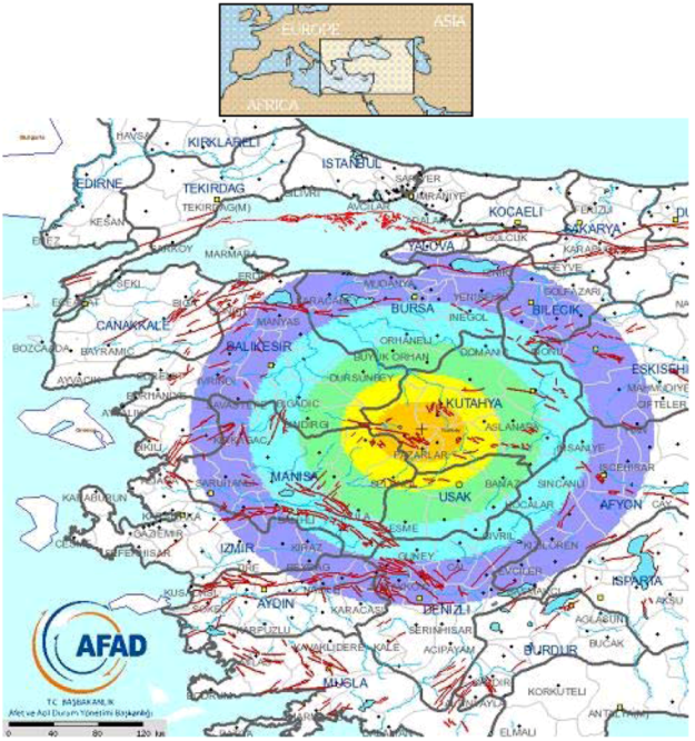
A—It was effective in a wide area: The earthquake was felt in neighboring provinces and a very wide region including the cities of Afyonkarahisar, Bursa, Eskişehir, Balıkesir, Çanakkale, Yalova, Denizli, İzmir, İstanbul, Tekirdağ and Ankara. Seismic intensity map of Simav Earthquake prepared by AFAD [
3] is shown in
Figure 1. One would assume this was a deep focus shock because the earthquake was felt in a wide region. On the contrary, three institutions reported that the earthquake was less than 10 km deep (7.0, 8.0, and 9.1 km in
Table 1) indicating that this was a shallow earthquake. Although AFAD [
3] reported that the focal depth of the earthquake was 24.46 km, we reached a conclusion that the earthquake had a shallow focus. Because there have been different opinions and the earthquake was felt in a wide area, a detailed analysis is needed; mechanisms of the shock needs to be researched by taking all faults into consideration.
Figure 1.
Seismic intensity map of Simav, Kutahya earthquake [
3] (orange color in the center corresponds to Mercalli scale VII, and the outer most circle corresponds to scale II).
Figure 1.
Seismic intensity map of Simav, Kutahya earthquake [
3] (orange color in the center corresponds to Mercalli scale VII, and the outer most circle corresponds to scale II).
B—It caused heavy damage: Although this was a moderate earthquake, it caused heavy damage to reinforced concrete and masonry buildings. The damage distribution reported by Governorship of Kütahya is given in
Table 2.
Table 2.
Damage distributions reported by Governorship of Kütahya [
1].
Table 2.
Damage distributions reported by Governorship of Kütahya [1].
| Damage level | Building | Dwelling | Office | Warehouse | Barn | Loft |
|---|
| Collapsed | 115 | 82 | 7 | 28 | 44 | 38 |
| Heavy | 1439 | 1725 | 117 | 464 | 436 | 122 |
| Moderate | 409 | 1209 | 280 | 202 | 45 | 25 |
| Slight | 5155 | 9097 | 719 | 2004 | 1178 | 133 |
| No damage | 5754 | 9204 | 1070 | 2086 | 600 | 209 |
C—It had many aftershocks: İnel
et al. [
5] reports that the aftershocks started immediately after the main earthquake and continued for a long time. During the first and second days after the main earthquake, 470 aftershocks occurred with a magnitude of 1.3 to 4.8. In addition to these initial afterschocks, 1629 aftershocks occurred during the first month after the main shock. According to AFAD [
3] 1322 of these shocks had a magnitude less than or equal to 3 (M ≤ 3), 292 had 3 < M ≤ 4, and 13 had 4 < M ≤ 5. Locations of these aftershocks can be seen in
Figure 2.
2. Soil Properties and Seismicity of the Region
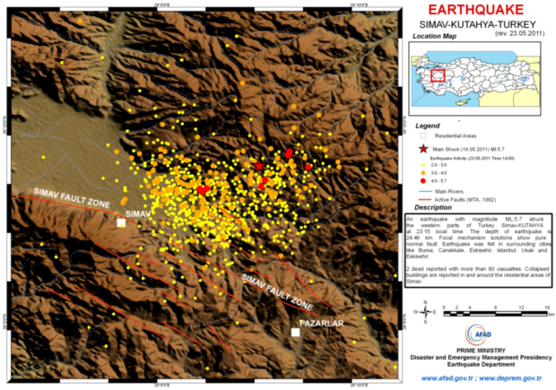
The Simav region is seismically very active (
Figure 2). Analysis of earthquakes that occurred in the area since 1900 shows that the 1928 M = 6.2 Emet, 1944 M = 6.2 Saphane, 1970 M = 7.2 Gediz, and 1970 M = 5.9. Cavdarhisar earthquakes caused the heaviest damage. On 17 February 2009, a moderate earthquake occurred in Simav (AFAD: M = 4.8; KOERI: M = 5.0) and some buildings were damaged. The maximum recorded ground acceleration was less than 0.05g near the epicenter [
6].
Figure 2.
Locations of Simav earthquake aftershocks [
3].
Figure 2.
Locations of Simav earthquake aftershocks [
3].
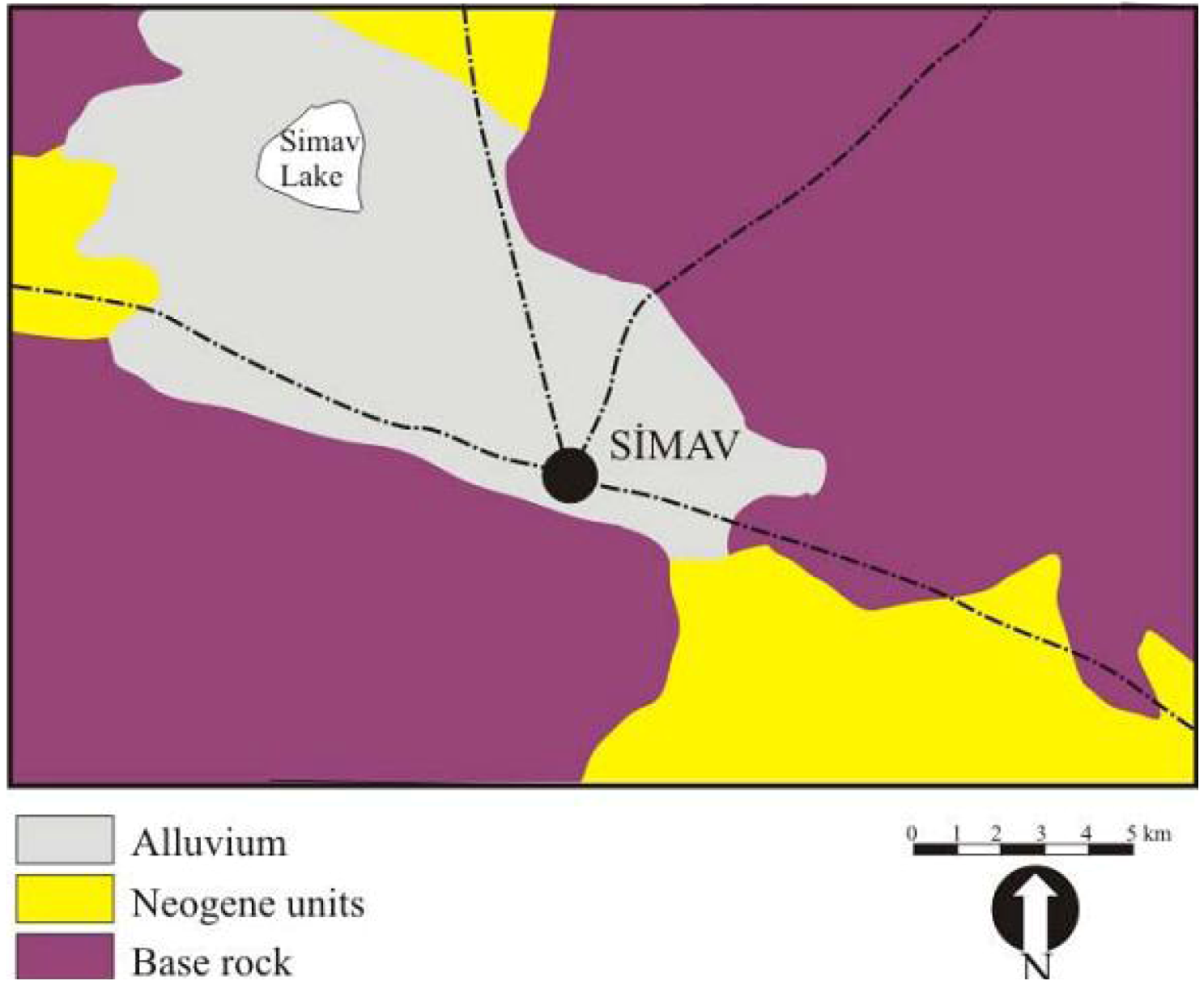
The fault zone called “Simav graben” extends from east to west, bordering Simav plain in the south [
7]. The fault zone between Sındırgı and Abide is 150 km long [
8]. This strike slip fault is right-lateral and started to have vertical component in time. Saroglu
et al. [
7] stated that 55 km around the fault zone, including the center of Simav, is probably still active. Another fault zone south of Simav includes a few parallel faults. In this region, Paleozoic old metamorphic units and Permo-Triyas old limestone passes the fault line. The fault zone changes direction and moves 3 km towards the north at approximately 25–35 km west of Simav. Because of this movement, the Simav depression zone started to become a full-apart basin. Because of this movement, the right-lateral strike-slip fault and Simav depression are very young [
8].
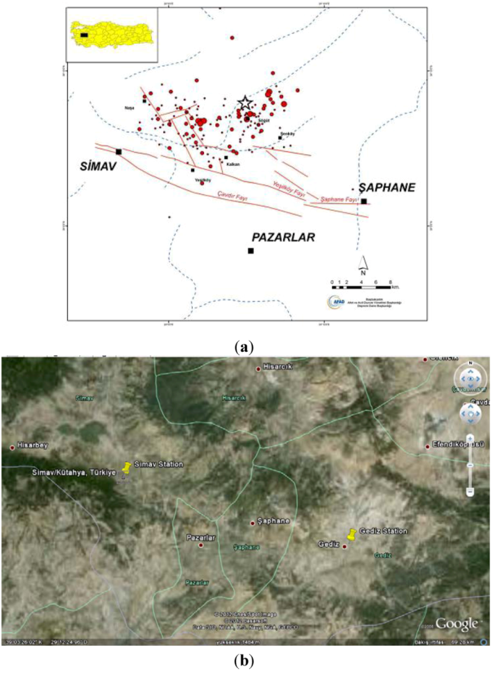
The earthquake occurred within the Simav fault zone, and under the pressure of two fault segments that are 16 and 22 km long, 2–3 km away from each other with north and northeast dipping beds.
Figure 3 shows that the Yesilkoy and Cavdir faults caused the quakes [
6] and the two nearest stations (Simav and Gediz). Simav station was located in Simav city center. Gediz station was to the east of Simav (31 km from epicenter).
Figure 3.
(
a) Fault lines near Simav—epcienter shown by star [
3]; (
b) and Google Earth view of Simav and Gediz Stations. (Star in the map indicates earthquake epicenter and circles represent afterschocks).
Figure 3.
(
a) Fault lines near Simav—epcienter shown by star [
3]; (
b) and Google Earth view of Simav and Gediz Stations. (Star in the map indicates earthquake epicenter and circles represent afterschocks).
4. Ground Motion Characteristics and Response Spectra for the Simav Earthquake
Maximum ground accelerations recorded near the epicenter and neighboring cities are provided in
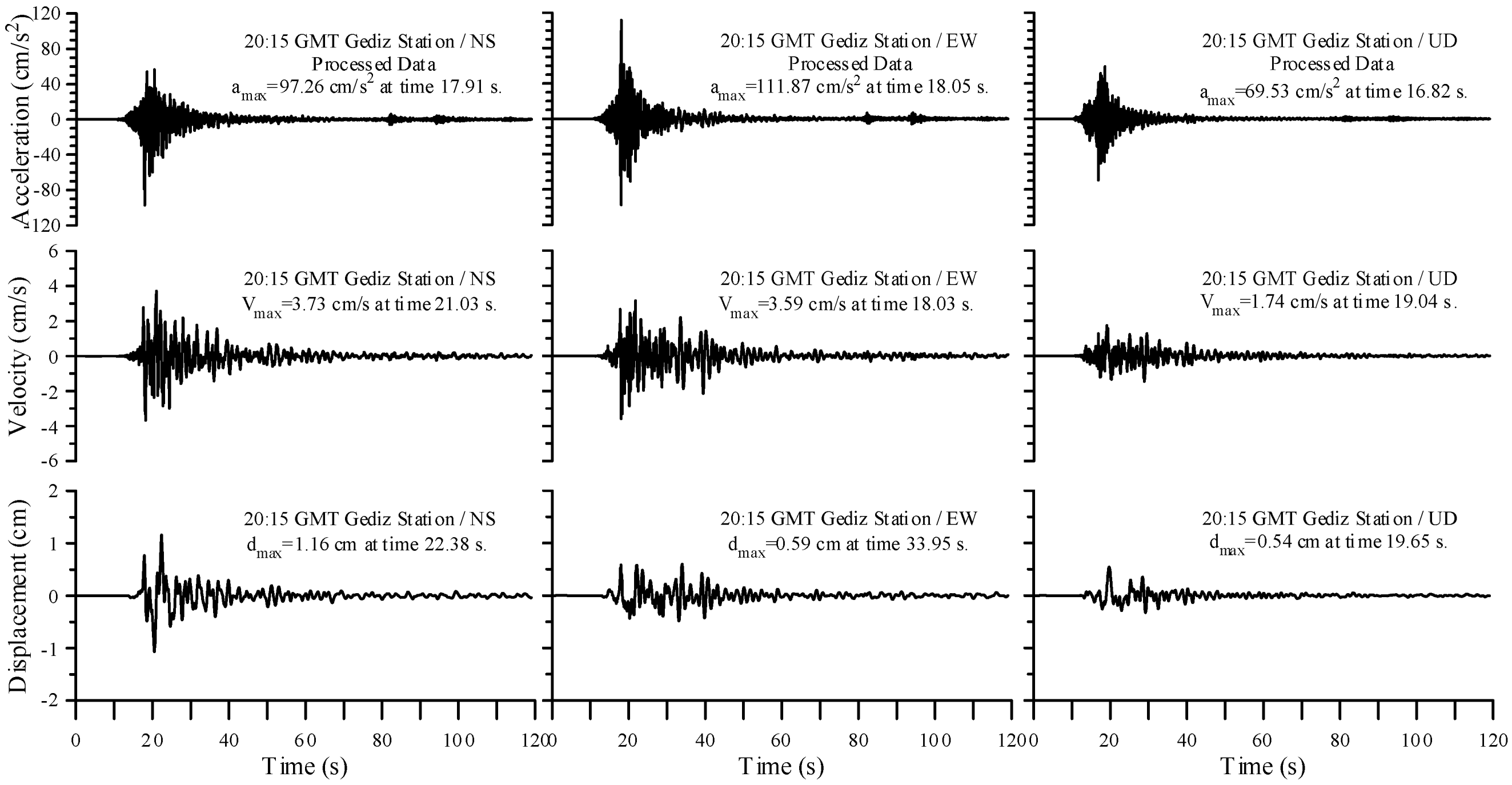
Table 3. Maximum ground accelerations recorded at the Gediz station (about 31 km away from the epicenter) were 103.9, 92.3, and 67.8 gal in the east-west, north-south, and vertical directions, respectively.
Figure 5 shows that the strongest earthquake motion continued for approximately 5 to 6 s and the average acceleration was 60–70 cm/s
2 at the Gediz station. The peak ground velocity was approximately 3.73 cm/s and peak ground displacement was approximately 1.16 cm, both occurred in the NS direction.
The current Turkish Earthquake Code [
9] specifies four seismic zones in Turkey; Zone 1 is the most hazardous zone while Zone 4 is the least hazardous one. Simav is located in Zone 1. The code requires a design acceleration of 0.4
g for the buildings located in Zone 1, where
g is the gravitational acceleration. The design acceleration is larger than the accelerations measured at some distance away from the epicenter (
Table 3). So, under normal circumstances, if the buildings were designed and constructed following the current seismic design standards, no significant damage would be expected.
Table 3.
Maximum ground accelerations measured during the May 19 Simav earthquake.
Table 3.
Maximum ground accelerations measured during the May 19 Simav earthquake.
| Station | Maximum ground Acceleration, gal | Distance to epicenter (km) |
|---|
| City | District | NS | EW | Vertical |
|---|
| Kütahya | Gediz | 92.33 | 103.92 | 67.83 | 31 |
| Kütahya | Emet | 74.69 | 73.13 | 46.34 | 27 |
| Bursa | M.K.Paşa | 29.40 | 62.04 | 16.74 | 116 |
| Uşak | Merkez | 47.87 | 46.91 | 23.14 | 58 |
| Bursa | Keles | 24.62 | 17.24 | 9.08 | 88 |
| Manisa | Akhisar | 18.00 | 17.32 | 5.33 | 112 |
| Balıkesir | Bandırma | 18.31 | 16.00 | 8.64 | 162 |
| Bursa | Mudanya | 13.65 | 15.11 | 5.93 | 125 |
| Bilecik | Bozüyük | 14.65 | 11.60 | 5.73 | 119 |
| Afyon | Dinar | 10.65 | 6.77 | 3.70 | 152 |
Figure 5.
Acceleration, velocity, and displacement histories recorded at the Gediz Meteorology Station during the 19 May 2011 Simav (Kütahya) earthquake.
Figure 5.
Acceleration, velocity, and displacement histories recorded at the Gediz Meteorology Station during the 19 May 2011 Simav (Kütahya) earthquake.
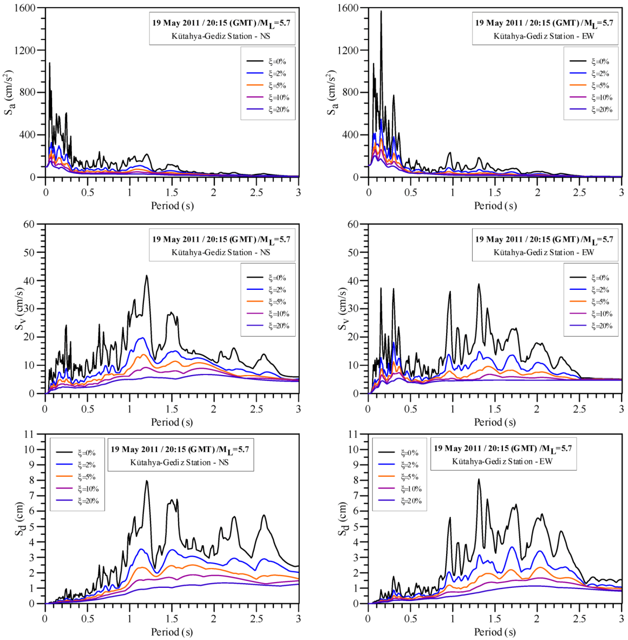
Figure 6 shows the acceleration, velocity, and displacement spectra with the damping ratios (ξ) of 0, 2, 5, 10, and 20% for the NS and EW components of the Simav earthquake ground motions recorded at the Gediz station. The response spectra shown in
Figure 6 indicate that peak spectral accelerations occur when the spectral acceleration is less than 0.4 s. It should be noted that the accelerations were recorded at the Gediz station, approximately 31 km away from Simav. The design spectrum specified by the Turkish Earthquake Code [
9] and the calculated acceleration spectra are compared in
Figure 7.
Simav station was located in the city of Simav (
Figure 3). The soil at the Simav station had mean shear wave velocity,
Vs30 of 259 m/s, and included gravel and sandy clay within the top 1 m, gravel and clayey sand between 1 and 5 m depths, less gravel, sandy clay and silt up to the depth of 20 m, sandy silty clay up to 22 m, and silty sand with limited gravel and clay between 22 and 30 m [
3]. Information from a borehole indicates that soil at the Gediz station included gravel and clayey sand fill within the top 2 m, sandy clay with some gravels between 2 and 6 m, sandy silty clay up to 11 m, clay and very weak claystone from 11 to 14 m, and claystone between 14 and 17 m depths [
3].
Figure 6.
Acceleration, velocity and displacement response spectra with different damping ratios for NS and EW components of the ground motion recorded at the Gediz station during the Simav earthquake.
Figure 6.
Acceleration, velocity and displacement response spectra with different damping ratios for NS and EW components of the ground motion recorded at the Gediz station during the Simav earthquake.
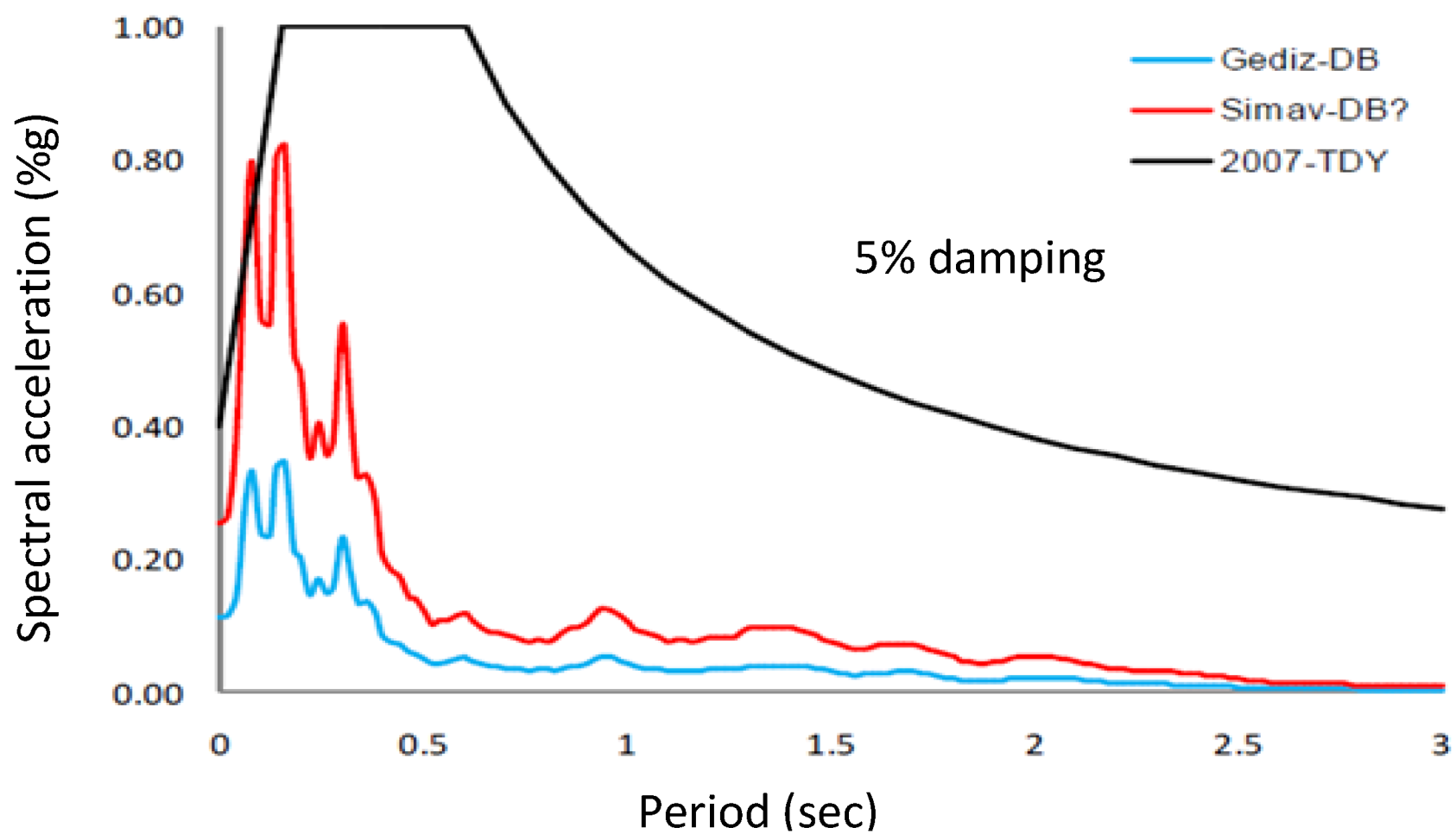
Condidering that the intensity of the 2011 Simav earthquake was moderate, the seismic force demand for design is less than what is required in the current code (
Figure 7). This indicates that the currently specified design spectral accelerations are appropriate for design level earthquake in this region. Inel
et al. [
12] predicted a peak ground acceleration of approximately 250 cm/s
2 in the Simav city center by interpolating the information gathered from other stations in the area.
Figure 7.
Spectral acceleration for the TEC [
9] Z3 soil class and spectral accelerations for ground motions (EW) recorded at Gediz and Simav stations during the Simav earthquake [
5].
Figure 7.
Spectral acceleration for the TEC [
9] Z3 soil class and spectral accelerations for ground motions (EW) recorded at Gediz and Simav stations during the Simav earthquake [
5].
5. Damage to Reinforced Concrete Structures
In Simav and nearby villages, three general structural load carrying systems are used: reinforced concrete, timber frames with masonry infill, and adobe load bearing walls which are usually reinforced with timber. Quality and type of buildings in Simav highly depend on the economy and living conditions of habitants in villages. While most of the houses are reinforced concrete frame buildings in the city center, houses in rural areas are built using different structural systems. Buildings in villages are mostly unengineered and one or two stories. These stone masonry buildings are typically more than 20–30 years old. The focus of this paper is on reinforced concrete buildings. Commonly observed damage in reinforced concrete buildings is classified below based on the cause of the damage.
The most common structural system in Turkey is the reinforced concrete beam-column space frame system with thick concrete joist floor system and infill walls including hollow clay bricks. In recent years, reinforced concrete shear walls have been used more regularly in high seismic regions to increase lateral load resistance. Also, for the last few years, in almost all reinforced concrete buildings, TOKI (Housing Development Administration in Turkey) has been using tunnel form without frame members and masonry infill walls.
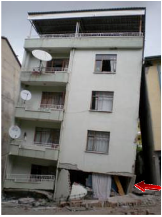
5.1. Soft and Weak Story
A weak or soft story in a building has relatively low lateral strength or stiffness compared to those of the stories above or below that story. Weak and soft stories are typically observed in the first story of reinforced concrete buildings in Turkey. In multi-story buildings the first story is used as garage, office space, or usually for commercial purposes. As a result, a typical first story has: (1) taller columns with resulting lower lateral stiffness; (2) much less infill walls between the columns leading to lower lateral strength and stiffness compared to upper stories; and (3) rectangular columns with their weak axis mostly perpendicular to the street,
i.e., weaker columns, thus weaker story in one direction [
10]. With less stiff, taller or weaker columns and less infill walls, the first story experiences larger lateral drifts. Soft and weak stories have been one of the most common reasons for damage or collapse of multi-story reinforced concrete buildings in Turkey [
10,
11,
12] and in other parts of the world [
13,
14]. In the building shown in
Figure 8, first story columns were severely damaged which led to collapse while the upper stories suffered virtually no damage. Even the windows are not broken in the upper stories because the deformation demand in the upper stories was limited.
Figure 8.
Building collapse due to first story failure during the Simav earthquake.
Figure 8.
Building collapse due to first story failure during the Simav earthquake.
Existing buildings with a soft or weak story can be strenghened by increasing the stiffness and strength of the soft or weak story. The TEC [
9] recommends addition of structural walls as a practical retrofit method. This strengthening is currently mandatory for existing buildings in seismic zones 1 and 2, which are the two seismic zones with the highest earthquake risk with corrresponding ground acceleration
ag ≥ 0.4
g and 0.3
g, respectively. These buildings typically consist of reinforced concrete flat slab, bare or infill joist system, and waffle slab system with columns and beams not satisfying the requirements for high ductility level.
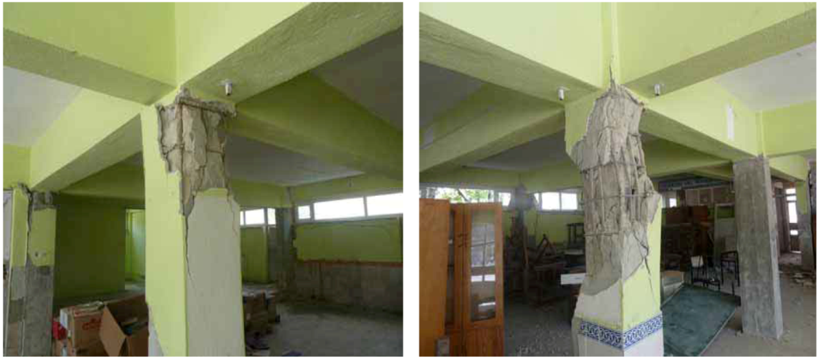
5.2. Strong Beam-Weak Column
Reinforced concrete frames need to be designed for both strength and ductility in order to prevent severe damage that can be caused during a strong earthquake. Strength is the maximum shear, axial or moment capacity of a structural member or the structural system to resist the earthquake loading, and ductility is related to maximum deformation capacity. In order to avoid collapse during an earthquake, columns need to be designed stronger than the beams in a reinforced concrete frame. This phenomenon is called strong column and weak beam concept. The beams are supposed to be ductile and controlled damage or plastic hinges are supposed to occur at end of beams rather than in columns. In order to dissipate sufficient energy within the plastic hinges, plastic hinge regions should have special reinforcement detailing to improve the energy absorption capacity and ductility. However, reinforced concrete frames with weaker columns suffer brittle shear and axial failure while the stronger beams remains elastic. This undesirable behavior is also seen in the 2011 Simav earthquake.
Figure 9 shows column failures in a building with strong beams and weak columns.
Figure 9.
The failure of strong beam-weak column.
Figure 9.
The failure of strong beam-weak column.
5.3. Short Columns
Many reinforced concrete buildings were seriously damaged in past earthquakes due to presence of short columns [
10,
15]. Short columns can be classified into two groups. The first group consists of columns that are designed or constructed shorter than other columns in that story. The second group includes columns that are shortened during construction by adding partial walls or panels on both or either side of the columns although their specified height is the same as other columns in that story in the original design. Damage in these short columns is often in the form of X-shaped cracking due to brittle shear failure. Examples of short column failures from the 2011 Simav earthquake are shown in
Figure 10.
Figure 9 and
Figure 10 show the large transverse reinforcement spacing in the columns. Widely spaced and insufficient transverse steel leads to: (1) lower column shear strength; (2) less effective confinement of the core concrete and lower core concrete strength; and (3) buckling of the longitudinal bars under increased axial and lateral loads. The effects of inadequate transverse reinforcement are further discussed below.
Figure 10.
Short column and non-ductile column failure.
Figure 10.
Short column and non-ductile column failure.
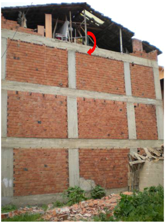
5.4. Unconfined Gable Walls
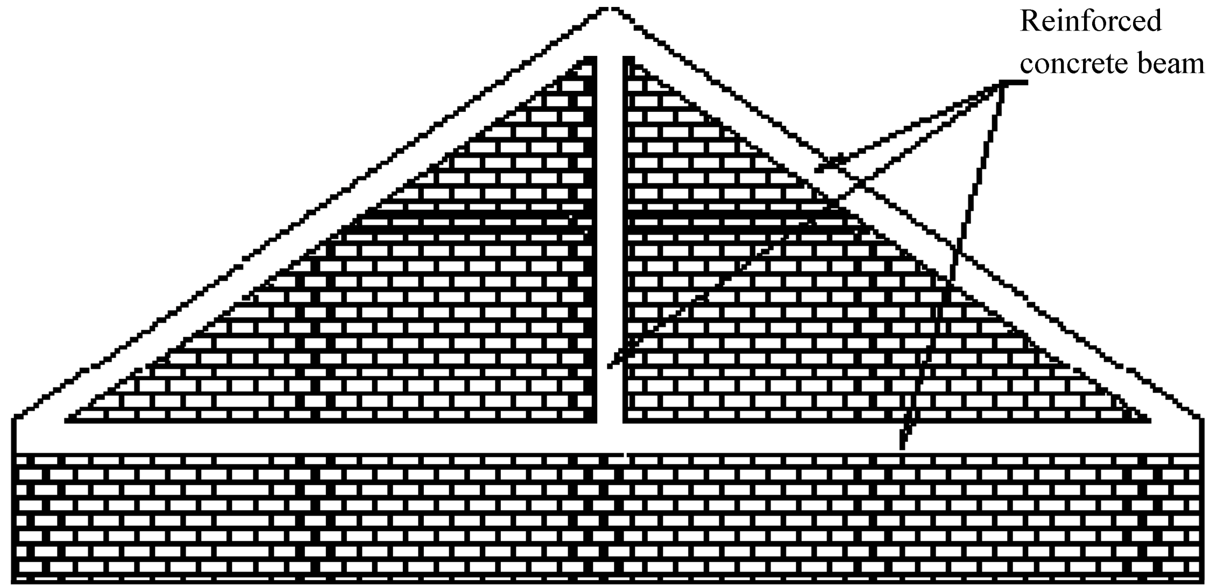
Unconfined gable wall damage has been common in recent earthquakes in Turkey. Although the structural integrity of the building is not compromised due to the gable wall damage, such damage results in falling hazard that leads to financial loss, injuries and even fatalities [
11]. An example of unconfined gable wall damaged in the Simav earthquake is shown in
Figure 11. In order to limit the gable wall damage, the Turkish earthquake regulations [
9] require vertical and inclined concrete beams within the wall if the roof gable wall is taller than 2.0 m (
Figure 12).
Figure 11.
Unconfined gable wall damage.
Figure 11.
Unconfined gable wall damage.
Figure 12.
Recommended reinforced concrete elements for gable walls.
Figure 12.
Recommended reinforced concrete elements for gable walls.
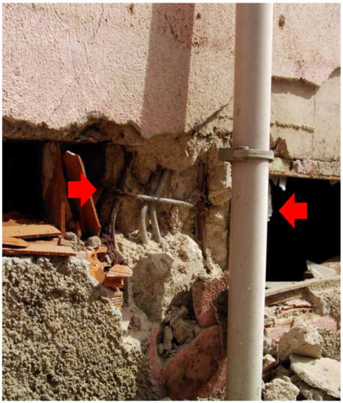
5.5. Inadequate Transverse Reinforcement
Transverse reinforcement in concrete members primarily confines concrete core, holds the reinforcement cage during construction, and provides lateral or shear strength. Typically, columns, sometimes shear walls, provide the main lateral load resisting mechanism in reinforced concrete frame buildings in Turkey. Therefore, the shear strength and ductility of columns are crtitical in seismic performance of concrete buildings. The amount and detailing of column ties are directly related to the lateral strength and deformation capacity of the columns. For example, 90-degree hooks at the end of column ties do not effectively carry shear forces and cannot confine the concrete at large displacements, usually resulting in brittle shear failure at a low lateral displacement or ductility. This is mainly because poorly detailed hooks open up as the shear force applied on the column increases. Sezen and Moehle [
16] provides evidence for shear strength degradation from experimental tests of full-scale column specimens with 90-degree hook ties.
In the TEC [
9], columns are divided into one central zone (near column mid-height) and two confinement zones (at column ends) in terms of transverse reinforcement spacing and detailing requirements. According to Turkish earthquake regulations, transverse reinforcement spacing in confinement zones of columns at high ductility level cannot be larger than or equal to 100 mm and one third of smaller column dimension. In columns of normal ductility level, transverse reinforcement spacing cannot be more than one third of smaller column dimension, eight times longitudinal bar diameter, or 150 mm. Transverse reinforcement spacing in the middle of columns can be less than or equal to 200 mm, half the smaller column dimension, or twelve times longitudinal bar diameter. Thus, the minimum transverse reinforcement spacing is limited to 100 mm in the column confinement zone, and 150 mm in the middle zone. The observed transverse reinforcement spacing in buildings damaged during the Simav earthquake were much larger than these limits.
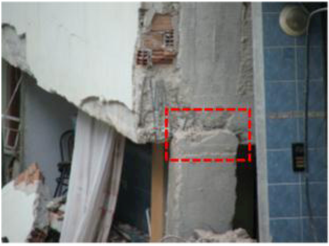
Beam-column joints are designed to transfer moments and resist lateral loads within the beam-column moment frame system. Transverse reinforcement needs to be provided within the joint region to resist shear forces and confine concrete [
17]. Some buildings were damaged in Simav because of insufficient lateral reinforcement in the beam-column joints (
Figure 13). No confinement or lateral reinforcement exist in most joints, making them unable to achieve the required ductility. Beam-column joints of high ductility frame systems are classified as confined or unconfined joints in the TEC [
9]. A beam-column joint is defined as a confined joint if beams frame into all four sides of a column and the width of each beam is not less than three quarters of the adjoining column width. In practice, it is rather difficult to satisfy this requirement. All joints not satisfying the above given conditions are defined as unconfined joints.
TEC [
9] requires 135-degree hooks at the end of seismic transverse reinforcement, because 90-degree hooks easily open and lose their effectiveness. As the labor or installation is difficult, transverse steel with 135-degree hooks has not been used until recently. However, with more government oversight and better supervision at the construction site, TEC [
9] requirements appeared to be carefully applied in the field within the last five years.
Figure 13.
Inadequate transverse reinforcement in beam-column joints.
Figure 13.
Inadequate transverse reinforcement in beam-column joints.
5.6. Inadequate of Longitudinal Reinforcement Arrangement
In general, S220a reinforcing steel with a yield strength of 220 MPa and S420a rebar with a yield strength of 420 MPa are used in Turkey. Rebar diameter ranges from 8 mm to 32 mm. It was found that mostly S220a reinforcing steel bars were used in the buildings in the region affected by the 2011 Simav earthquake. According to TEC [
9] minimum rebar diameter for slabs, joists, and columns is 8, 12, and 14 mm, respectively.
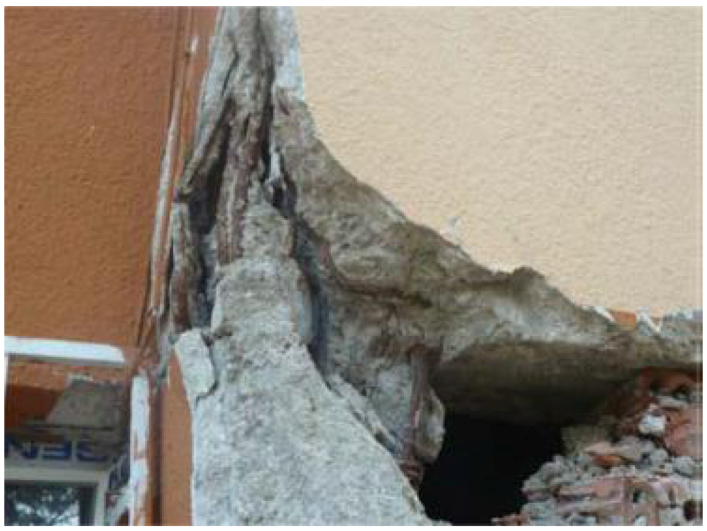
As discussed in the previous section, reinforcement detailing is critical in sesimic design of reinforced concrete structures because the ultimate strength and displacement ductility highly depend on the amount and detailing of the reinforcement. The authors observed severe damage and collapse of structures mainly due to poor reinforcement detailing (
Figure 14). Most common problems included insufficient or lack of longitudinal bars, and insufficient development length, lap splices, or anchorage of rebar. These problems were exacerbated by corrosion of rebar and concrete damage and spalling. Although the corrosion was typically not severe in longitudinal bars in buildings damaged during the earthquake, some corroded rebar were spotted typically at the column-foundation interface.
Figure 14.
Poor reinforcement detailing at a column end [
6].
Figure 14.
Poor reinforcement detailing at a column end [
6].
5.7. Pounding of Adjacent Buildings
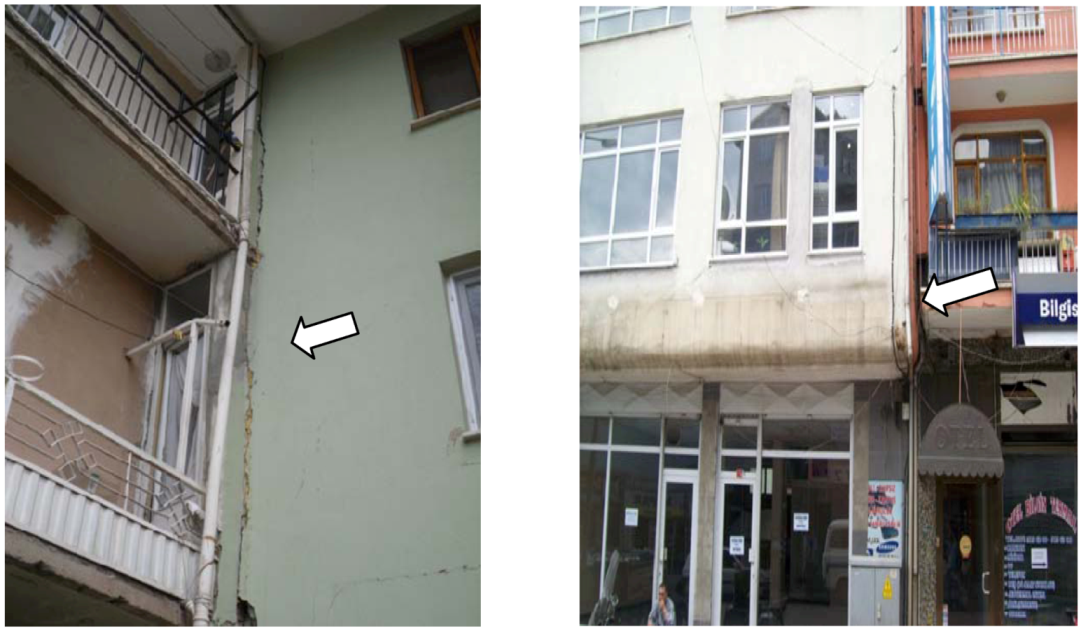
If the gap between adjacent buildings is insufficient, pounding between closely spaced buildings with different dynamic characteristics can be a serious threat in seismically active areas. Structural periods of two adjacent structures cannot always be the same because periods of the buildings depend on variation of mass and structural system stiffness of the building. Dynamic properties of structures, properties of ground motion and gaps between closely spaced structures have influence on the location and magnitude of pounding. In addition, soil type can affect the structural response in terms of both fixity of the building foundations and periods of the structures. The simplest and most practical way to prevent this impact and reduce damage is to provide enough separation. Corner buildings are expected to experience more damage than interior buildings because of pounding, since corner buildings are free to move in many directions. If the required sufficient space or gap cannot be provided, an alternative solution is to decrease the lateral motion and drift of buildings. Pounding of closely spaced buildings is frequently observed during earthquakes in Turkey because it is very common to have very small separation or no gap between adjacent buildings. Two pounding examples resulting from inadequate gap between adjacent buildings are shown in
Figure 15.
Figure 15.
Pounding between closely spaced buildings.
Figure 15.
Pounding between closely spaced buildings.
5.8. Poor Concrete Quality
Low material quality is an important factor that affects the seismic response of buildings. Damage resulting from low quality material was observed in many earthquakes all around the world [
18]. In Simav, most of the older structures were constructed with hand-made concrete. Ready-mixed concrete has been used only recently (especially after the 1999 Turkey earthquakes) in Simav and some rural regions of Turkey. As a result, it is not uncommon to find very low compressive concrete strength in some buildings. Low quality of concrete usually results from lack of sieve analysis and proper gradation of aggregate, lack of vibration after concrete pouring, insufficient curing of concrete after construction without attention to weather conditions. Tests of concrete samples taken from buildings by Pamukkale University in Simav showed a compressive strength of 6 to 12 MPa much lower than the minimum required strength of 18 MPa [
19].
5.9. Infill Wall Damage
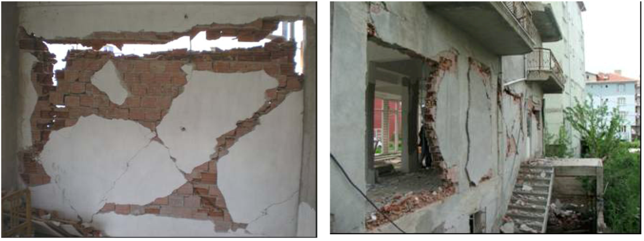
Unreinforced hollow clay bricks were used in infill walls of almost all reinforced concrete buildings in the region affected by the 2011 Simav earthquake. Unreinforced infill walls have relatively low lateral strength and usually brittle once their strength limit is reached. Diagonal cracks, a sign of shear failure, in infill walls were commonly observed in reinforced concrete buildings. Depending on the magnitude of the lateral load applied on the building, the level of observed wall damage varied from light diagonal cracks in the walls to separation from the structural frame or out-of-place buckling (
Figure 16).
Figure 16.
Infill wall damage in reinforced concrete buildings. Damage Caused by Multiple Earthquakes.
Figure 16.
Infill wall damage in reinforced concrete buildings. Damage Caused by Multiple Earthquakes.
Simav was also hit by a magnitude 5 earthquake in 2009, causing damage in some reinforced concrete buildings. Most of these damaged buildings apparently were not repaired or strengthened, instead they were plastered and painted. The 2011 Simav earthquake caused further damage in those buildings usually at or near the areas damaged during the 2009 earthquake.
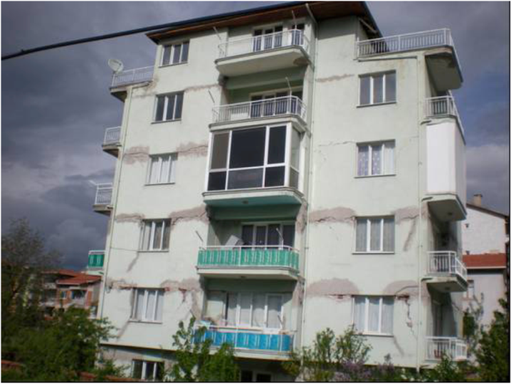
Figure 17 shows one such building with damaged beams and infill walls plastered after the 2009 earthquake. Large cracks caused by the 2011 earthquake are visible in the second floor, e.g., near the right end of the wall in the second story.
Figure 17.
Building damaged during the 2009 and 2011 earthquakes.
Figure 17.
Building damaged during the 2009 and 2011 earthquakes.


