1. Introduction
For many years, a commonly used technique for ventilating buildings in Sweden is mechanical ventilation with heat recovery. This technique is also predominant for passive houses and other types of low energy buildings. It offers an efficient recovery of the heat from the exhaust air and results in a high thermal comfort for the residents of the building.
However, the fans needed for the ventilation system often cause noise and consume electrical energy. An investigation by the Swedish Energy Agency showed that the best performing ventilation system in the test consumed 456 kWh of electrical energy annually to run the fans [
1]. This number is also in close agreement with data given in [
2]. The following example can be used to illustrate a problem. A typical house in the Swedish climate consumes about 4000 kWh to heat the outdoor air. If the system recovers 75% of the heat it means that 3000 kWh is saved annually.
However, the 456 kWh of electric energy corresponds to about 1370 kWh of primary energy, using a conversion factor of three. This strongly reduces the energy savings in the system. Instead of saving 75% the system only saves about 40% of the primary energy including the electricity for the fans in the calculations.
One alternative to this is to use a natural ventilation system, driven by stack effect and wind induced pressure. This kind of technique normally lacks the possibility to recover energy from the outgoing ventilation air. If heat recovery is absent, the consequences will be a high energy demand and a high peak power load for buildings located in cold climates. At the same time, this type of technique easily results in low comfort due to cold draught. Also, the ventilation flow rate is strongly dependent on the wind pressure and the temperature difference between the indoor and the outdoor air. If the wind is absent and the temperature difference is close to zero, the ventilation rate will be unacceptably low. However, between the natural and the mechanical ventilation types, there is a combined technology called hybrid ventilation. This technique uses the natural driving forces when these provide sufficient pressure difference and utilizes a complementary fan otherwise. The hybrid technology combines the low electrical energy consumption for natural ventilation with the high reliability using fans. From an economical point of view hybrid ventilation has the potential for cost savings, especially with regard to installation costs [
3]. This reference is also recommended for further reading. The standard heat exchangers used in modern ventilation technique introduces a high pressure drop. These heat exchangers are not possible to use in a system using natural ventilation. Instead, new heat exchangers with very low pressure drop have to be developed if the hybrid ventilation system is to be equipped with heat recovery.
Many different solutions have been suggested to utilize the hybrid ventilation technology. Schultz
et al. [
4] suggested a system driven solely by the temperature difference between the indoor and the outdoor temperatures, having a heat recovery efficiency of up to 43%. Hviid [
5] designed a heat exchanger made of bent plastic tubes reaching a heat recovery of about 75%. Shao [
6] presented a system utilizing heat pipes to recover and transport heat from the exhaust air to the fresh incoming air with a heat recovery efficiency of up to 70%.
However, there are problems related to all of the techniques. One main disadvantage is the restrictions imposed on the architecture. Tall chimneys and extensive ducts decrease the flexibility of the system. The size of the heat exchangers is rather large making it difficult to fit in modern buildings. This might introduce problems for the architects. If these heat exchangers are made more compact the pressure drop will increase, making them less suitable for natural or hybrid ventilation.
This paper presents a low pressure drop heat exchanger, suitable for hybrid ventilation systems. The ventilation system is intended to be used in cold climates where heat recovery from the outgoing ventilation air is needed in order to optimize energy consumption and thermal comfort. Heat recovery might not be essential in hot climates or in buildings with large internal gains from electrical appliances. The main focus has been to develop a heat exchanger with a low flow resistance at the same time as the heat recovery efficiency was kept high. Theoretical calculations were performed for different geometries in order to meet these demands. A compact heat exchanger also has the possibility to be used when old houses with natural ventilation systems are renovated in order to lower the energy consumption. These houses normally lack heat recovery making them highly energy consuming or alternatively poorly ventilated. Apart from the economical reasons also the level of discomfort due to cold draught can be reduced if the recovered energy heats the incoming air.
The heat recovery rate from the ventilation air is heavily dependent on the air tightness of the building, regardless of what system is being used. If the building is not airtight the air will enter and leave the building through slats in the envelope. This uncontrolled ventilation decreases the possibilities to recover the heat and thus the total power need will increase. This is for instance discussed in [
7]. Uncontrolled ventilation and leakage is also a problem for older houses. The ventilation system discussed in this article offers an alternative to the commonly used mechanical ventilation systems. However, the building skin in old buildings might still need to be renovated in order to achieve high heat recovery with the installed ventilation system. The main benefit with the proposed ventilation system is that no additional ventilation ducts are needed, as is the case when mechanical ventilation with heat recovery is installed. The existing ducts in the building can instead be used for the proposed hybrid ventilation system.
The local climate is also of major importance for the heat recovery system. If the heat exchanger has a high heat recovery rate at the same time as the ambient temperature is very low there is a risk of frost forming on the heat exchanger surface as the water condenses and freezes. This frost can limit or even block the ventilation in the building. This problem can be solved in many different ways. Typical solutions can be to defrost the heat exchanger using an electrical heater or to by-pass the incoming cold air from the heat exchanger and in this way us the heat from the outgoing air to defrost the exchanger. Another solution is to pre heat the air before passing it through the heat exchanger. This pre heating of the ventilation air can be carried out by letting the air pass through a ground duct before entering the building and the heat exchanger. Different systems addressing solutions to this problem are described in [
8].
3. Theoretical Considerations for the System
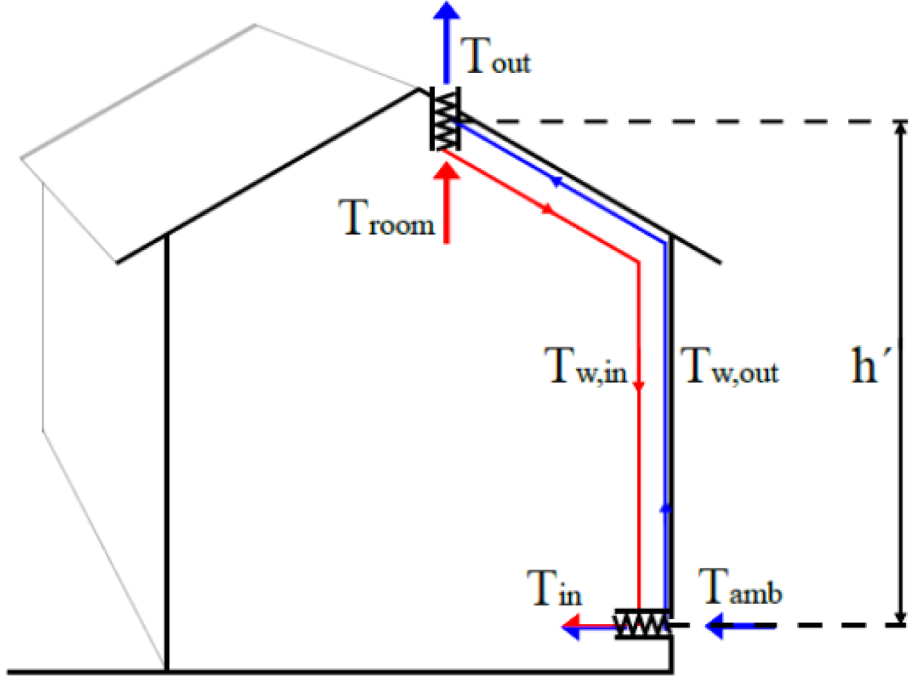
The heat recovery system is built on two fluid-coupled heat exchangers. The air flow is driven by natural forces, due to wind pressure and temperature differences. The brine is circulated by a pump. One of the liquid-to-air heat exchangers is placed as high as possible under the roof, see
Figure 1. This exchanger recovers some of the energy from the outgoing air and transfers it to the brine. This energy is then pumped to the bottom of the building where the other heat exchanger is located. This liquid-to-air heat exchanger delivers the recovered heat to the incoming cold fresh air. After this heat exchange the cold liquid is pumped back to the heat exchanger under the roof and the circuit is completed.
Figure 1.
The liquid based heat recovery system.
Figure 1.
The liquid based heat recovery system.
The driving forces for the ventilation system are very limited. The thermal driving pressure can be calculated by:
where
h´ is the height difference between the ventilation openings of the building;
g is the gravitational constant; and
ρamb and
ρroom are the densities of the ambient and the indoor air respectively.
From this it becomes apparent that the heat exchanger at the roof should be located as high as possible to maximize the driving forces for the system. If the height
h´ of the building is 10 m and the ambient and the room temperature is 0 °C resp. 20 °C the driving force will be:
It is clear that the pressure losses have to be kept low in the whole system. The driving pressure created by the temperature difference has to balance not only the losses in the heat exchanger but also losses in the ducts, filters etc. It is thus a large advantage if the duct system can be considered superfluous. At the same time it is beneficial if the heat exchanger surface is easy to clean making it possible to install a minimal, or even better, no filter at all. Both of these measures will lower the pressure losses in the system. One way to reduce the amount of ducts in the system is to allow the fresh supply air to go directly through the wall to the rooms. However, the fluid circuit in the system transporting the recovered heat has to be divided to reach every fresh air inlet. Instead of an air supply system, this type of ventilation system instead has a fluid supply system.
If the system is intended to work during periods with lower temperature differences, the pressure drop in the heat exchangers has to be kept low. If the ambient temperature increases to 10 °C at the same time as the indoor temperature is kept constant, the driving force will be reduced to 4.4 Pa. This driving pressure has to match not only the two heat exchangers but also a complementary fan, a small amount of ducts and other ventilation details such as grills,
etc. Fans for hybrid ventilation systems with a pressure drop less than 2 Pa during inactive periods,
i.e., when the blades of the fan are not spinning, can be found on the market [
9]. If the duct work is considered early in the building process the pressure drop from it can be kept low. The consideration can for instance be to avoid too many bends and narrow ducts. If planned correctly the pressure drop can be limited to less than 1 Pa. This means that about 2 Pa are left for the two heat exchangers,
i.e., the pressure drop for one heat exchanger can be allowed to be approximately 1 Pa. However, the forces created by the wind can also be used. These forces are however much more irregular as they change with the wind which varies a lot. Thus, there can be large differences from the wind induced forces from day to day. If these forces can be used or are to be considered as a disturbing force is left out of this article. This has to be considered for each specific case where wind conditions and available pressure from thermal forces,
etc., are weighted together.
4. Theoretical Considerations for the Heat Exchanger
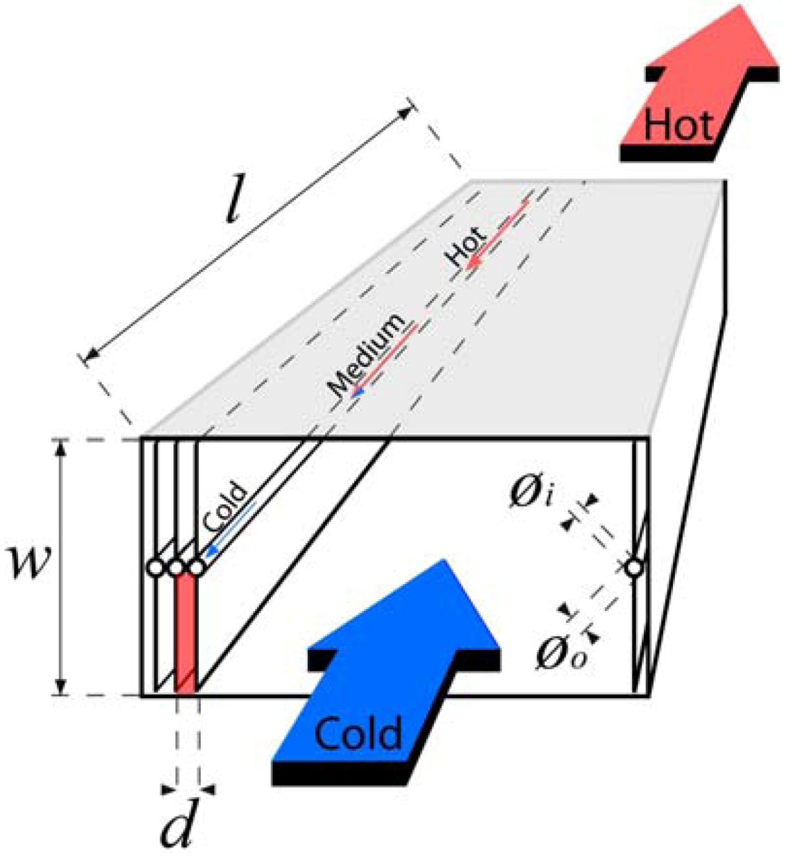
The counter flow liquid-to-air heat exchanger is shown in
Figure 2. The heat exchanger is made up from of a number of solar collector absorbers. The absorbers are produced by Ssolar in Sweden. The absorbers, from now on referred to as fin pipes, are placed in parallel and connected to a manifold on each side. The copper pipe used as the manifold has 2 mm wide drilled holes connecting it to the fin pipes. The fin pipe is made up of a copper pipe tightly pressed in between aluminum fins. The width,
w, of the fin pipe was chosen to be 167 mm and the thickness,
t, of the fin is 0.5 mm. This size is a standard component from the supplier. The pipe at the center of the fin pipe has an outer diameter,
øo, of 9.5 mm while the inner diameter,
øi, is 8 mm. The length,
l, of the heat exchanger was treated as variable to meet the heat transfer efficiency requirements. The blue and red large arrows in the figure illustrate the air flow while the small arrows at the water pipe illustrate the water flow. This type of fin pipes is mass-produced, resulting in a low price. This is of course essential for the economical considerations for this type of system.
Figure 2.
The liquid-to-air heat exchanger.
Figure 2.
The liquid-to-air heat exchanger.
One clear advantage with this design compared to many other heat exchangers is that it can be cleaned. If the cover is removed the fins can be cleaned. In
Figure 2, the top, marked with grey color, can be removed. Furthermore, the heat exchanger can easily be divided into many smaller units. These smaller heat exchangers can be located in every bedroom and living room separately. In this way the air flow rate can be set individually for the different rooms.
The heat exchangers are designed to have a thermal efficiency
η = 50% on a system level. The efficiency is defined as the temperature change for the incoming air divided by the difference in temperature between the ambient and the indoor. During the calculation we assume an ambient temperature of 0 °C. The efficiency is calculated as:
A normal ventilation rate for a residential house of approximately 150 m² is 180 m³/h. This corresponds to 50 L/s and results in an air change rate of about 0.5 air changes per hour. If the heat recovery efficiency is 50% and the ambient and the indoor temperatures are 0 °C and 20 °C respectively, the heat exchanger needs to deliver:
where
Fa is the air flow rate;
ρa is the density of the air;
CPa is the specific heat of the air; and Δ
Ta is the temperature change for the air that passes through the heat exchanger. If the heat exchanger has an efficiency of 50% and the ambient temperature is 0 °C the inlet air temperature will be 10 °C. Assuming that the brine flow rate is adopted to give the same size of temperature change as the ventilation air,
i.e., 10 °C, the brine temperature will drop from 15 °C to 5 °C as it is cooled in the heat exchanger. In the roof exchanger, the air will be cooled from 20 °C to 10 °C at the same time as the brine temperature is increased from 5 °C to 15 °C. This results in a constant temperature difference of 5 °C between the brine and the air. A general formula for calculating this temperature difference, Δ
Tw−a, can be expressed as:
In order for a system to be efficient,
i.e., for two heat exchangers in series, 50% of the ventilation heat recovery, the efficiency on the component level,
i.e., for a single heat exchanger, has to be higher. In the example above, the efficiencies for the individual heat exchangers are:
If ΔTw−a = 5 °C, the two heat exchangers needs to have a UA-value of 128 W/K.
Heat transfer calculation, air side: Assumptions made for the theoretical calculations are:
Steady-state conditions;
One-dimensional conduction;
Negligible radiation heat transfer;
Constant properties;
Fully developed flow and temperature profile through each cell.
As can be seen in
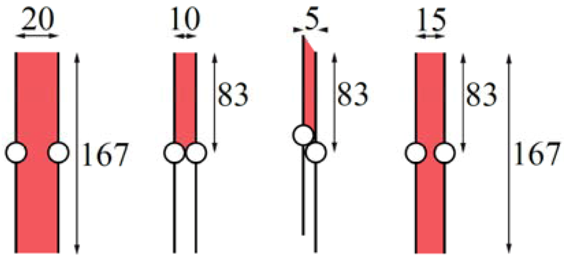
Figure 2, the fin pipes and the walls create small cells in which the air can move. One such cell is illustrated in red transparent color. The number of such parallel cells was kept as a variable during the calculations. The width of the cell,
w/2, is 83 mm. The distance
d between the fin pipes was used as a variable to be able to find a suitable pressure drop and a high heat transfer rate. The performed calculations will be presented using 80 fin pipes connected in parallel and the spacing will be assumed to be 11 mm between the fin pipes. If the total air flow is 50 L/s, the velocity of the air can be calculated to be approximately 0.34 m/s. The hydraulic diameter for the rectangular tube,
i.e., the cell indicated with red in
Figure 2, is calculated as:
where
Ac is the flow cross-sectional area; and
P is the perimeter of the cell [
10]. The height of the cell is set to 83 mm, half of the fin pipe. This was done since the fin pipes are so densely packed that they divide the cells shown in
Figure 2. If the pipes where smaller the width of the cells would instead be 167 mm. This is discussed further in the section labeled “complication”.
The Reynolds number for flow in a circular tube, or noncircular tubes using the hydraulic diameter, is defined in Equation (7). If the density
ρa of the air is taken at 5 °C it is 1.251 kg/m³,
um ≈ 0.34 m/s is the fluid mean velocity,
D =
Dh = 0.019 m is the diameter of the tube and
μ = 17.4 × 10
−6 N·s/m² is the viscosity:
The numbers given above result in a ReD-number of 478. This number is far less than the approximately 2300 that is normally considered as the onset of turbulence. The air flow can thus be considered to be laminar.
The heat transfer coefficient
ha is calculated from Equation (8):
In Equation (8)
ka is the thermal conductivity for air; and
NuD is the Nusselt number.
NuD for noncircular tubes can be found in reference [
10]. The ratio of the sides in the cell,
i.e., 83 mm and 11 mm, is approximately 8. The Nusselt number was thus set to 6.49. This is valid for fully developed thermal conditions. The real heat transfer coefficient is higher if thermal entrance effects are present.
Churchill and Ozoe [
11] developed an expression for
NuD that covers both the entrance and the fully developed thermal region. This work was reproduced in [
12].
NuD for a circular tube can be calculated as:
where
Gz is the Graetz number calculated as:
where
Pr is the Prandtl number. This means that the average
NuD number for a one meter long tube with parameters corresponding to the air side of the heat exchanger investigated in this article will increase with approximately 15%. All of the investigated geometries for the heat exchanger,
i.e., different
d, were adjusted with 15%.
In [
10] the fin efficiency is defined as:
where
Lc is the corrected fin length defined as:
and
m is defined to be:
where
P is the fin perimeter. The thermal resistance for one unit length of the fin pipe,
Ra, associated with this heat transfer can be calculated by:
Heat transfer calculation, copper pipe: the thermal resistance for one unit length in the copper pipe can be calculated using:
where
kCu is the thermal conductivity for copper.
Heat transfer calculation, water side: in order to maximize the heat recovery in the system the temperature increase of the air has to be equal to the temperature drop of the water. If the air flow rate and the temperatures are known the water flow rate in each fin pipe can be calculated as:
where ñ is the number of fin pipes the flow has been split into. This results in a velocity of the water of:
This low velocity results in a Reynolds number of:
This is far smaller than the limit of 2300 for turbulent flow and thus the Nusselt number for the water fluid will be 4.36 [
10] assuming laminar, fully developed thermal conditions and uniform surface heat flux. Including the effects from the thermal entrance region, see Equation (9), increases the
hw value by approximately 2%. The heat transfer coefficient h can be calculated with:
where
kw is the thermal conductivity of water. The thermal resistance for one unit length of the pipe is calculated using:
Heat transfer calculation: The total heat transfer resistance for one unit length,
Rtot, can finally be calculated by:
The total heat transfer rate for one unit length, with a temperature difference of Δ
T is thus:
This means that the heat exchanger needs a total fin length of:
The numbers presented in Appendix shows that the total needed length of heat transfer fins is approximately 70 m. If the load is shared between 80 parallel fins, see
Figure 2 for explanation, it means that each heat exchanger fin needs to have a total length of about 1 m. A 1 m long heat exchanger with the above-described geometry would thus be expected to have an efficiency on a system level of 54%. As discussed around Equation 5, the efficiency on the component level differs from the system level. A 54% system efficiency corresponds to 70% efficiency on the component level.
7. Experimental Setup
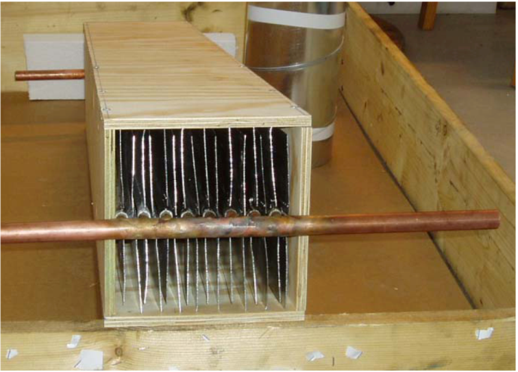
The performed experiment on the heat exchanger was performed on a 1 m long unit with 16 parallel connected fin pipes, see
Figure 2 and
Figure 4. This is 1/5 of the size for the supply air heat exchanger for a whole building. The same size of heat exchanger is needed on the roof. The tested heat exchanger can thus be viewed as a heat exchanger used in, for instance, a bedroom. The total fin pipe length is 16 m and the total fin area is approximately 5.3 m². The 16 fin pipes were connected to manifolds. This is shown in
Figure 4. The cross section of the heat exchanger is approximately 0.17 m·0.17 m and the length is 1 meter. The soldering of the fin pipes to the manifolds could not be performed in a straight line, due to lack of space between the pipes. Consequently, the fin pipes had to be placed in a zigzag pattern leaving small gaps between the fins and the wooden sides of the heat exchanger. Any effects on heat exchange and pressure drop from this was neglected.
Figure 4.
The fin pipes soldered to the manifold in the heat exchanger.
Figure 4.
The fin pipes soldered to the manifold in the heat exchanger.
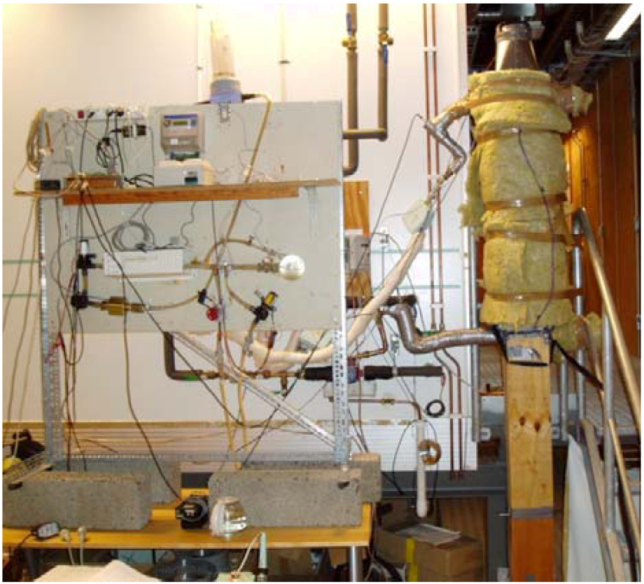
The wooden box surrounding the heat exchanger was insulated with 50 mm polystyrene and 90 mm glass wool. The test rig can be seen in
Figure 5. The controllable fan was installed on top of the heat exchanger to create an under-pressure. Sucking the air through the heat exchanger created a much steadier and a more well-defined air flow compared to blowing air into the exchanger from below. The air was allowed to travel through a duct of the same size as the surrounding wooden structure of heat exchanger in order to stabilize the airflow. This can be seen below the insulated heat exchanger in
Figure 5. Air at approximately 22 °C,
i.e., room temperature, was used as inlet air instead of using cold ambient air. This simplified the performed tests significantly. Furthermore, the inlet brine temperature was varied between approximately 30 °C to 60 °C.
Figure 5 shows the heat exchanger and the heat rack used to keep the inlet brine temperature constant. The rack is equipped with a heater connected in series with a cooler. When operated simultaneously the brine temperature can be kept stable.
Figure 5.
The heating rack is shown to the left and the insulated heat exchanger is shown to the right.
Figure 5.
The heating rack is shown to the left and the insulated heat exchanger is shown to the right.
The air temperature measurements were carried out with a thermocouple for the incoming air. In order to have a high resolution on the temperature difference for the incoming and outgoing air in the heat exchanger, a thermopile was used. The water temperatures were measured using PT100 sensors. The water flow was measured using a MP115 hall sensor from Kamstrup and the air flow was measured using an air flow hood, SWEMA Flow 125. A Campbell CR10 data logger from Campbell Scientific in Logan, UI, USA, was used to collect the measured data. A hot wire anemometer, Swema 31, was used to check the air flow profile in the duct. This assured an even distribution of air in the heat exchanger. The pressure drop measurements were carried out with a Digima Premo. The pressure drop was measured during operation with no heat exchange between the water flow and the air flow. As can be seen in the table the largest uncertainty is in the flow measurement for the air. The hot wire anemometer, Swema 31, was also used to measure the air flow. The measurement from the Swema 31 confirmed the measurements from the Swema air 125. Since the heat exchanger was thoroughly insulated the energy loss to the sides was limited. Less than 2% of the heat transferred from the water to the air disappears through the sides. This means that what is lost by the water should be gained by the air. This was also the case for all the measurements. This is a good check for the measurements.
Technical data for the measurement devices are shown in
Table 1.
Table 1.
The sensors used in the experiment.
Table 1.
The sensors used in the experiment.
| Product | Range | Accuracy | Comment | Manufacturer |
|---|
| Swema air 125 | 2 to 125 L/s | 10%, not less than 1 L/s | Back pressure measurement. Compensate for the pressure drop from the equipment itself. Manufacturers data. | Swema, Farsta, Sweden |
| Kamstrup, MP115 | 0.015 to 3 m³/h | Not available from manufacturer | Calibrated outside the standard range.Error < 4% for all ranges. | Kamstrup, Skanderborg, Denmark |
| PT-100 | <200 °C | 0.3 °C | 0.3 °C accuracy in the used temperature range. Manufacturers data. | Pentronic AB, Gunnebo, Sweden |
| Thermo pile | <350 °C | 2% | Manufacturers data. | Built in Lund University, Energy and Building Design, laboratory |
| Swema 31 | 0.1–30 m/s | 0.04 m/s | Used to check flow profile. Manufacturers data. | Swema, Farsta, Sweden |
| Digima Premo | 0.1–1999 Pa | 0.1 Pa or 0.25% | Manufacturers data. | SI—special instruments GmbH, Nördlingen, Germany |
8. Results
All the results from the measurements in this section are from a heat exchanger made up of 16 parallel fin pipes. However, the results were recalculated to numbers for a full heat exchanger with 80 parallel fin pipes. Results for the full size heat exchanger were selected for presentation since this gives the true numbers for a heat exchanger in a normal one-family house.
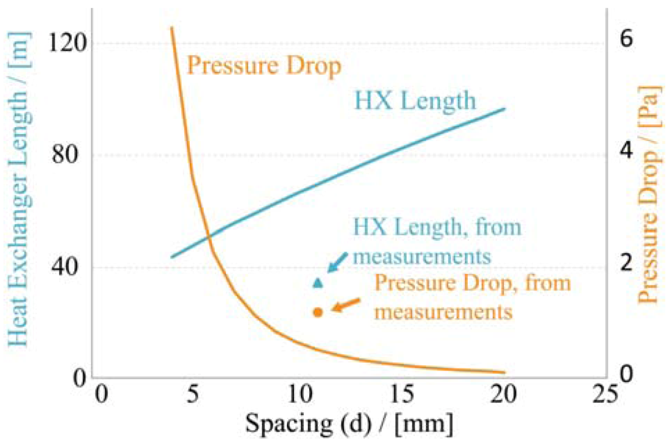
Results from the theoretical calculations are shown in
Figure 6. On the x-axis is the spacing between the fin pipes in mm, see
Figure 2 for explanation. The left y-axis shows the total of the 80 parallel connected fin pipes needed in order to have a heat recovery of 50% on a system level,
i.e., 66% on component level for the individual heat exchangers. The right y-axis shows the pressure drop for the different spacings. As can be seen in the figure the pressure drop increases exponentially as the cells gets smaller. A separation of less than 4 mm would result in a pressure drop higher than the 8.7 Pa discussed in the section labeled “theoretical considerations for the system”. Conclusions made from the graph led to the production of a heat exchanger with 11 mm spacing between the fin pipes. At this point the pressure drop is still low while the length is reasonably short. If the pressure drop were to be reduced further, the total length of the heat exchanger would be much larger. This would increase the production costs for a future product. Alternatively the heat exchanger has to be made up from a greater number of fin pipes. However, this makes the heat exchanger larger and thus more difficult to use. A decrease in the length of the heat exchanger would results in a higher pressure drop. This would make the pressure drop too high and the system would not work as intended. This is discussed further in the Discussion section.
Also shown in
Figure 6 are the resulting length and pressure drop for a system efficiency of 50% recalculated from the measurements.
Figure 6.
Heat exchanger length and pressure drop in order to have 50% system heat recovery efficiency as function of the spacing between the fins. The points show the resulting length and pressure drop for a system of 50% recalculated from the measurements.
Figure 6.
Heat exchanger length and pressure drop in order to have 50% system heat recovery efficiency as function of the spacing between the fins. The points show the resulting length and pressure drop for a system of 50% recalculated from the measurements.
The measurements on the heat transfer rate were performed with different inlet water temperatures. The results from the measurements can be seen in
Table 2. See
Figure 1 for explanation. The efficiency
ηcomp is the average efficiency for the water side and the air side. All of the results presented in
Table 2, except
ηcomp, are measured data. In
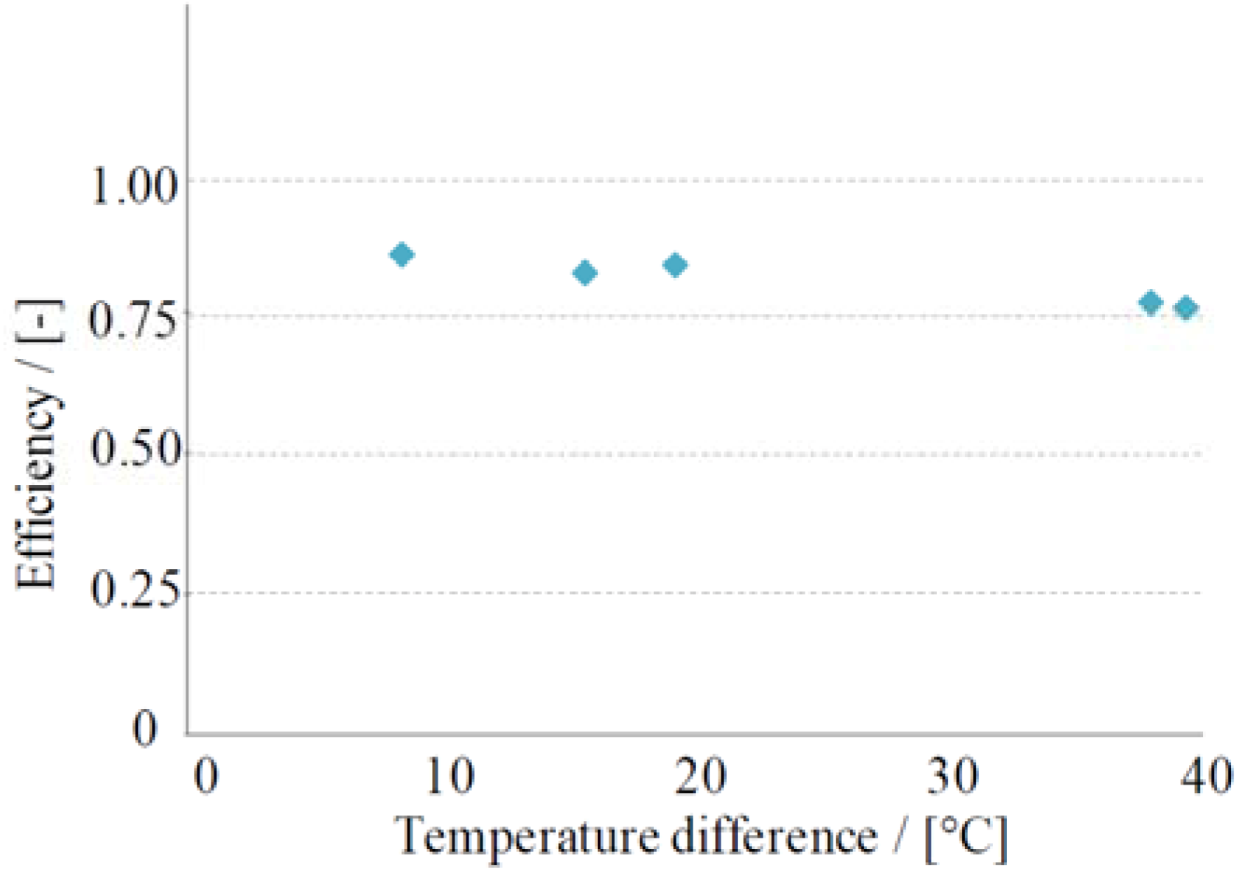
Figure 7 the component efficiency is plotted as a function of the temperature difference between the incoming water and the incoming air. The results show a tendency for higher efficiencies for lower inlet water temperature. The efficiency is calculated as an average of efficiencies for the water side and the air side.
Table 2.
The performed measurements for the heat transfer rate.
Table 2.
The performed measurements for the heat transfer rate.
| Measure No. | Tw,in | Tw,out | Δ
Tw | Fw | Tamb | Tin | Δ
Ta | Fa | ηcomp |
|---|
| (°C) | (°C) | (°C) | (mL/s) | (°C) | (°C) | (°C) | (L/s) | (-) |
|---|
| 1 | 31.51 | 24.56 | 6.96 | 2.6 | 23.32 | 30.40 | 7.08 | 9.1 | 0.86 |
| 2 | 38.92 | 25.74 | 13.17 | 2.7 | 23.29 | 35.86 | 12.57 | 9.5 | 0.82 |
| 3 | 42.50 | 26.71 | 15.79 | 2.6 | 23.29 | 39.67 | 16.38 | 9.0 | 0.84 |
| 4 | 61.00 | 31.00 | 30.00 | 2.7 | 23.15 | 51.48 | 28.33 | 9.8 | 0.77 |
| 5 | 61.72 | 32.13 | 29.59 | 2.7 | 22.16 | 52.79 | 30.63 | 9.5 | 0.76 |
Figure 7.
The measured component efficiency as a function of the difference in temperature between the incoming water and the incoming air.
Figure 7.
The measured component efficiency as a function of the difference in temperature between the incoming water and the incoming air.
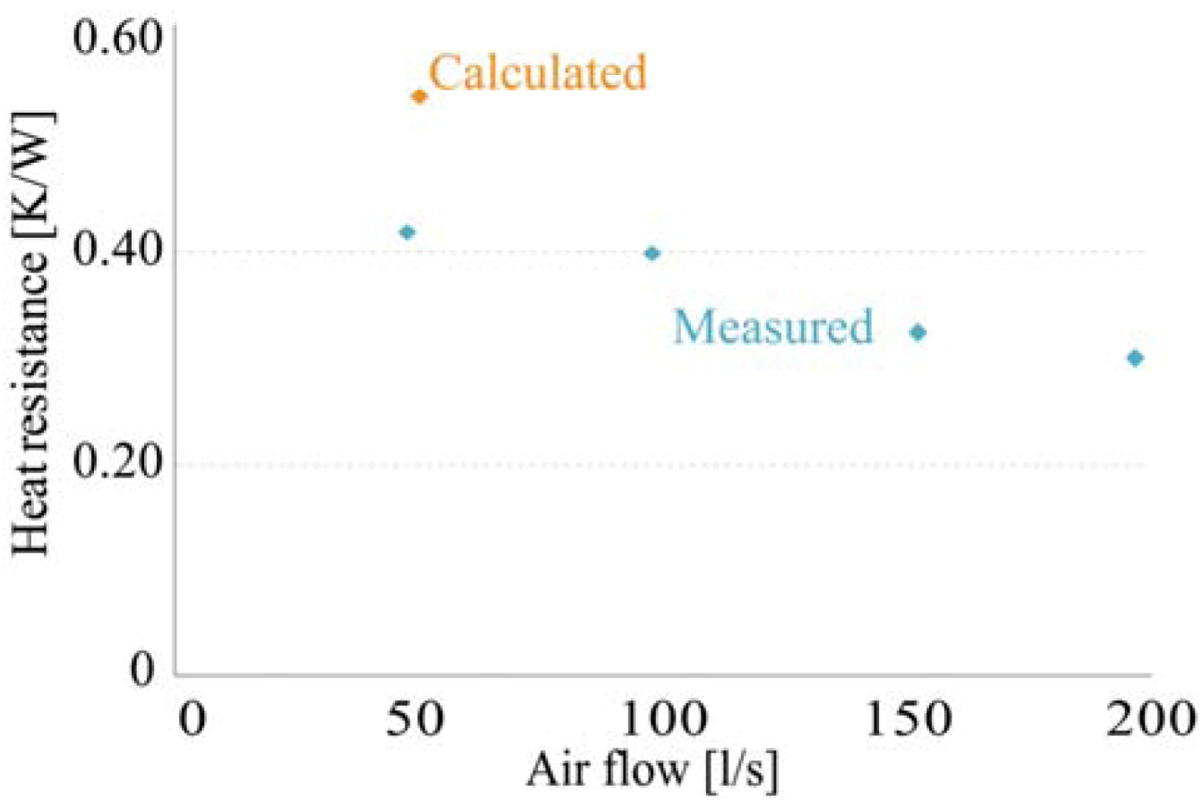
Measurements were also performed for the heat transfer rate for the heat exchanger for different ventilation rates.
Figure 8 shows the results. On the x-axis is the air flow rate in L/s and on the y-axis is the heat resistance for the heat exchanger calculated per meter fin pipe per degree difference in Kelvin. In orange is the calculated heat resistance and in blue are the measured values for the different measured ventilation rates. There is a clear trend for reduced heat resistance as the air speed is increased. This indicates a presence of vortices in the airflow, which increase with an increase flow speed.
Figure 8.
Heat resistance as a function of the air flow rate. In blue are the measured values and in orange is the calculated value.
Figure 8.
Heat resistance as a function of the air flow rate. In blue are the measured values and in orange is the calculated value.
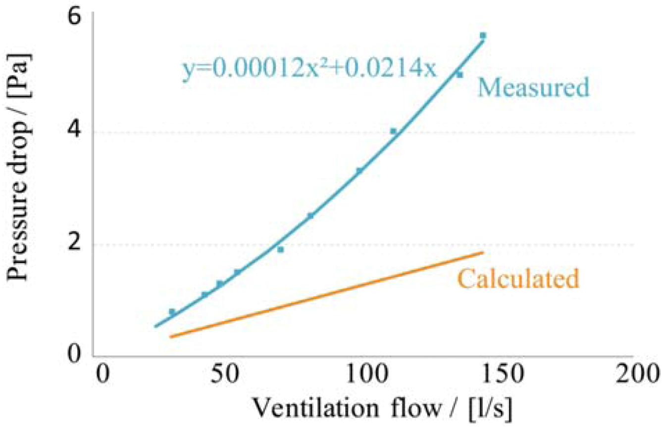
The most critical parameter for the heat exchanger is the pressure drop on the air side. If this is too high the ventilation rates will be low. Results from the pressure drop measurements can be seen in
Figure 9. In orange is the calculated pressure drop for different air speeds. The calculations were performed assuming no turbulence in the air flow. The figure also shows the measured pressure drop over the heat exchanger. This is shown in blue. The measurements indicate a turbulent component in the air movement. This is apparent even at low air speeds. The pressure drop for normal operation air speed used in a standard one-family house is approximately 1.3–1.4 Pa per heat exchanger,
i.e., 2.6–2.8 for both heat exchangers.
Figure 9.
Calculated pressure drop for a heat exchanger in red and measured pressure drop in blue.
Figure 9.
Calculated pressure drop for a heat exchanger in red and measured pressure drop in blue.
The discrepancy between the theoretical results,
i.e., designing the heat exchanger to have 50% system efficiency,
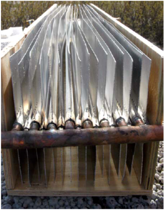
i.e., 66% component efficiency, and the experimental results discussed in this section could partly be explained by the fin pipes not being perfectly straight. A photo of the heat exchanger is shown in
Figure 10. These non-straight fin pipes give rise to a disturbed path for the air through the cells. This wavy movement will increase the heat transfer rate as the air in the cell will be forced to collide with the fin pipes. Simultaneously, it will add resistance for the air; hence the pressure drop will increase. This is also seen in the measurements presented in
Figure 6 where it is shown that the heat transfer rate is increased, and thus the needed length of fin pipes is reduced. At the same time the pressure drop is increased. The heat transfer rate and the pressure drop both increases approximately in a similar manner. In
Figure 9 it was shown that the air flow has a turbulent component already at low air speeds. This indicates the same conclusion. One other factor that has the potential to increase the heat transfer rate and pressure drop is the turbulence created by the manifold and the blunt ends on the fins. The effective area is also slightly larger than the theoretical area. The performed calculation does not include the area for the copper pipe, nor does it take heat transfer from the wooden box or the manifold into account.
Figure 10.
The heat exchanger. The fin pipes are not straight, resulting in a wavy path for the air through the exchanger.
Figure 10.
The heat exchanger. The fin pipes are not straight, resulting in a wavy path for the air through the exchanger.
Equations (20) and (24) can be scaled linearly to fit the results from the measurements.
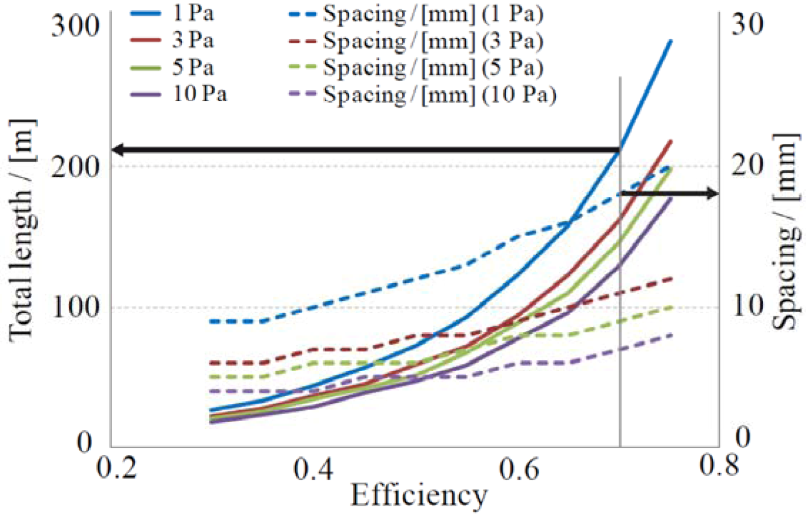
Figure 11 shows the system performance,
i.e., for both the heat exchangers at ground level and the roof heat exchanger. This means that the presented numbers are for the sum of both of the heat exchangers. The efficiency is calculated including the scaling factors
C1 and
C2. The full lines illustrate the total length of fin pipes needed as a function of system efficiency for the ventilation. The blue line is the length needed for a specific efficiency with a maximum pressure drop for the system of 1 Pa,
i.e., the pressure drop for both of the heat exchanger at the air intake and the air outlet. The red line shows the same but for 3 Pa, the green line is for 5 Pa and the purple line is for 10 Pa. The dashed lines show the distance between the fin pipes,
i.e., the distance
d in
Figure 2, to build that specific heat exchangers. The arrows in the Figure show an example. To have a 70% system efficiency with a pressure drop of 1 Pa the heat exchanger needs to have a spacing,
d = 18 mm, and a total length of fin pipes of approximately 210 m. The blue dashed line is for the 1 Pa pressure drop heat exchanger, the red, green and purple are for the 3, 5, and 10 Pa pressure drop heat exchangers, respectively.
Figure 11.
Total length of the heat exchanger on the left y-axis and spacing between the fins on the right y-axis as a function of system efficiency for the ventilation for four different total pressure drops, 1, 3, 5 and 10 Pa.
Figure 11.
Total length of the heat exchanger on the left y-axis and spacing between the fins on the right y-axis as a function of system efficiency for the ventilation for four different total pressure drops, 1, 3, 5 and 10 Pa.
9. Discussion
A reason for the increased pressure drop over the whole range is that the fin pipes fins were not perfectly parallel. This can be seen in
Figure 10. The metal fins were all somewhat wavy, giving rise to more narrow passages for the air as it travels through the heat exchanger. This will increase the pressure drop. However, this also has the potential to increase the heat transfer rate. This was also indicated in
Figure 6 and in
Figure 8 where it was shown that the measured heat transfer rate was higher than the calculated. This led to a shorter, more compact, heat exchanger than expected. The increased heat transfer and pressure drop can also be partly explained by turbulence occurring due to the manifold. This irregularity disturbs the air flow. At the same time it also contributes to the heat transfer. This heat transfer was not included in the theoretical calculations.
Figure 11 shows that the savings in fin pipe length is not very significant even if the pressure drop is allowed to increase. For instance, allowing the pressure drop in the system to increase from 3 to 5 Pa for a system efficiency of 70% only reduces the total fin pipe length from 153 m to 138 m,
i.e., about 10%. If the pressure drop needs to be smaller it is better to use the possibility with using more fin pipes. If the heat exchanger is produced with 160 parallel connected fin pipes instead of the 80 discussed in this article the speed of the air and thus the pressure drop would be reduced by 50%. The effects on the heat transfer rate for this new design have to be evaluated experimentally. In
Figure 8 it was showed that the heat transfer rate is dependent on the speed of the air. If the heat transfer rate is affected only slightly the total meter of fin pipes should be the same. Using more fin pipes is however not without problems. As the heat exchanger becomes wider it also becomes more difficult to install it. At the same time there is a greater risk of having uneven flow if the heat exchanger gets too big.
It was mentioned in the result section that if the pressure drop was increased when reducing the length of the heat exchanger the system would not work as intended. Still, this could very well be a good solution. What is needed is then a small fan. This small fan can provide the extra pressure needed to run the system if a smaller spacing of the fin pipes is chosen. It could be a good investment to spend a few Watts on a fan if the heat recovery is increased. This is a difficult question and more simulations on a building level are needed to answer it.
In the introduction section it was stated that the mechanical ventilation system recovers 40% of the primary energy. This does not imply that mechanical ventilation systems should not be used. This is an illustration of a problem. The difficulties of drawing conclusions from this are also indicated in [
14] where a number of different investigations are summarized. The energy savings when installing mechanical ventilation with heat recovery differ strongly. Even negative energy savings was found. What transformation factor to use for the electricity is a long discussion with many different answers. However, the energy consumption from the pumps also has to be included in the calculation. According to a manufacturer the annual energy consumption for pumping the brine for a one family house is estimated to 27 kWh. The recommended pump can be found at the Wilo webpage, [
15]. This number is much lower than the energy consumption for running the fans in the mechanical ventilation system. Furthermore, the introduction section briefly discussed pre heating of the incoming ventilation air by passing it in the ground before entering the building. The discussed ventilation system can utilize the same kind of pre heating. This can be carried out by passing the brine after being cooled in the heat exchanger at the air intake in the ground outside the building. This has a potential to decrease problems related to frost in the heat exchangers at the same time as energy is gained from the ground.

