1. Introduction
Japan, one of the most seismic areas in the world—since it is located between four different tectonic plates—is also periodically exposed to typhoons. Here, the need for heavy coverings emerges, not only to avoid the collapse of buildings due to storms, but also to reduce the effects of the earthquakes that periodically occurred in that area. Finally, Japan’s population, of 130 million inhabitants, lives in only 30% of a total land area of 380,000 km
2. The rest of the country is covered by mountain forests. Hence, wood as a building material is a natural approach. The history of extreme natural events strongly influences the traditional construction techniques, as discussed by authors in the case of earthquakes [
1,
2] or storms [
3,
4] and as demonstrated by Japanese multistory pagodas [
5,
6,
7].
The proposed system is based on the Japanese technique named
Merikomi. It consists of a sort of natural “pre-compression” method. The word is composed of two parts:
Meri, which means “taking away” and refers to the joints made by wood, and
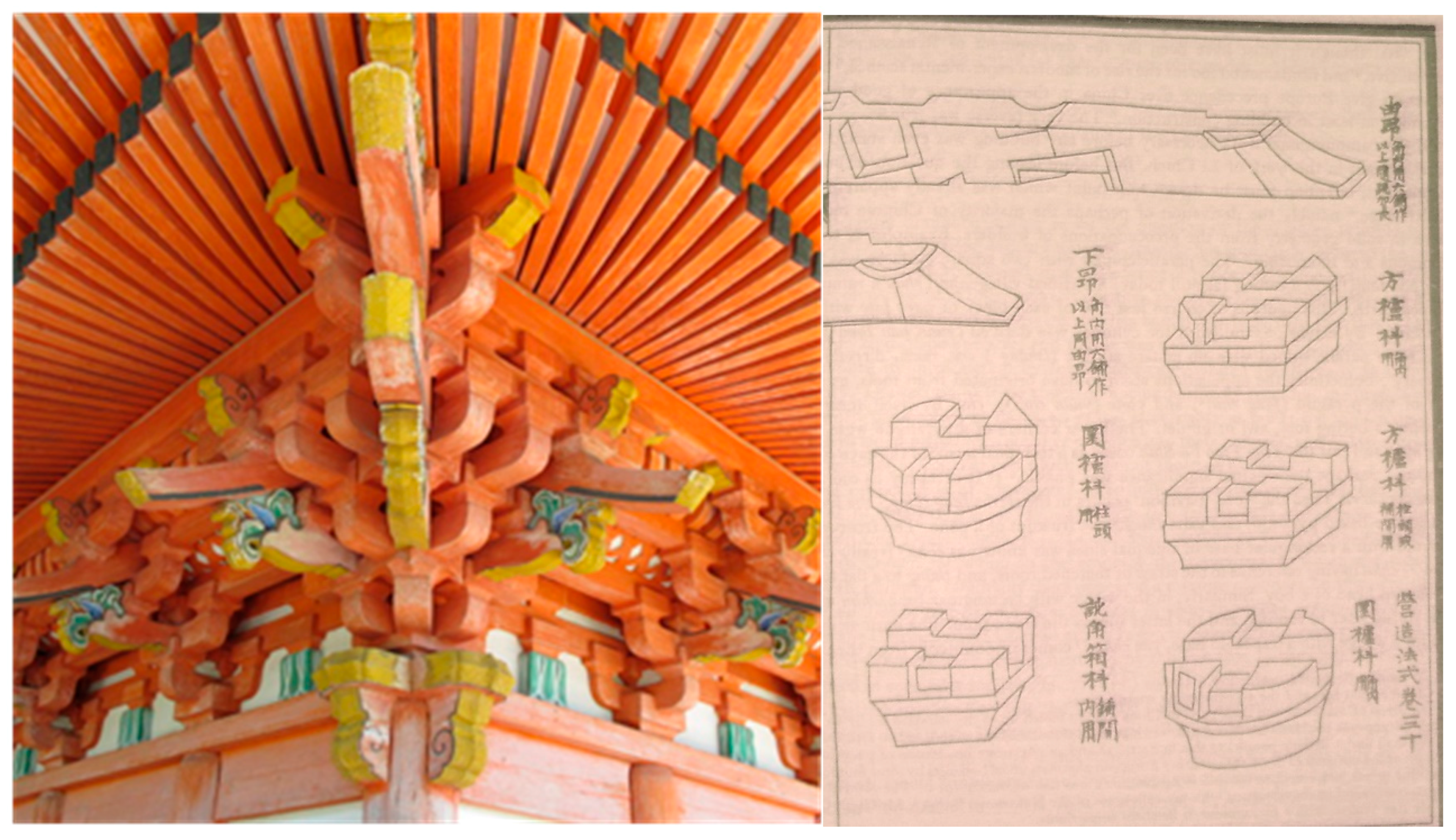
Komi, meaning “include”, which refers to the mounting technique discussed below. This system exploits the favorable deformation perpendicular to the grain (which is usually the weak point of this anisotropic material), making it a highly effective node in the case of earthquakes. The concept of
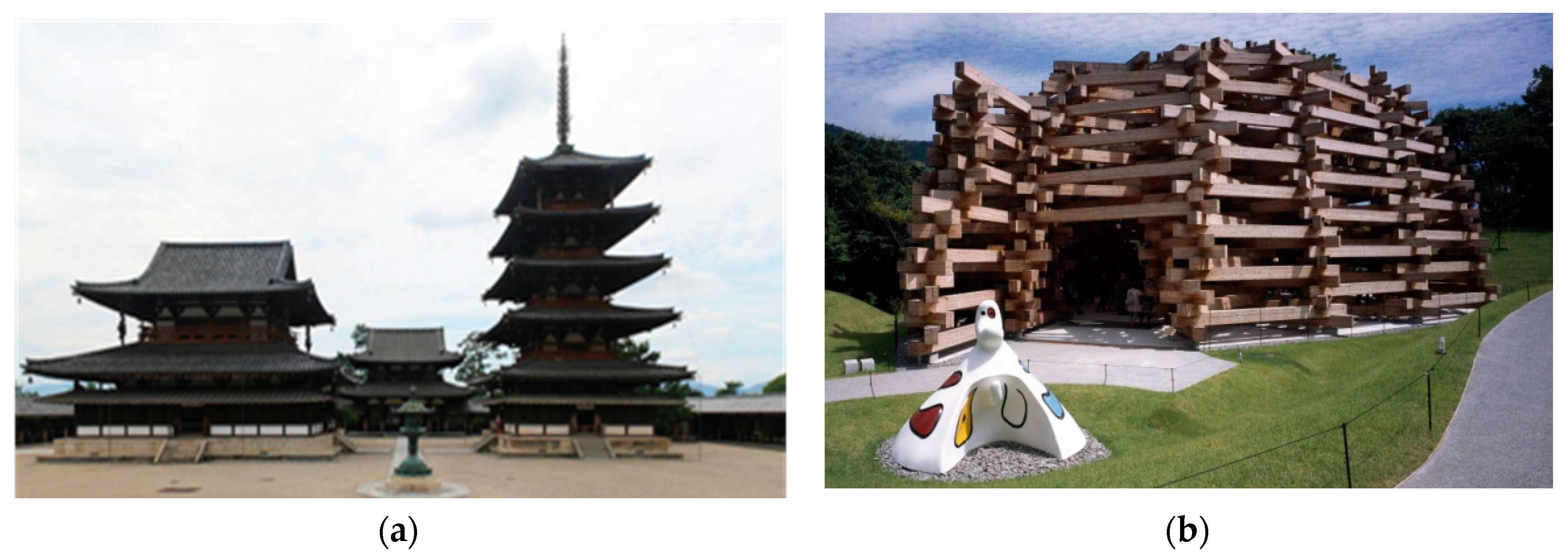
Kumimono (literally
interlacing), or the intricate knots present in all Japanese temples (
Figure 1), is also involved. The tradition of the Kumimono system is common to all East Asian countries [
8]; firstly in China (where it is called
Dougong) [
9] together with Korea and Vietnam, among others. A couple of examples of Kumimono solutions are shown in
Figure 2. Recent cases include the Swiss Pavilion at Expo 2000 (Hannover, Germany) by Peter Zumthor and the Prostho Museum Research Center (Kasugai-shi, Japan) by Kengo Kuma and Associates. The latter, derived from the interlocking system of a traditional game (
Chidori), posed analogous assembly problems.
The work described here was commissioned by JETRO (Japan External Trade Organization) to Atsushi Kitagawara Architects (AKA). The Ishimoto Architectural and Engineering Firm developed the engineering concept. The production was entirely done by Galloppini Legnami Borgosesia and the mounting was managed by general contractor Takenaka Europe.
The structure is made by only four standard elements of wood-laminated Japanese larch. Each of them is 208 cm long with a squared section of 115 mm. The nearly 20,000 pieces of Japanese larch arrived by container ships, docking at the harbor of Genua. Each element was protected by several layers of cellophane, aluminum, and bags of dehydrated salts, to prevent the formation of condensation and were therefore ideal environments to avoid possible attacks from wood-eating organisms.
Humidity measurements, made with an electric hygrometer, have even shown that the material delivered to Galloppini's warehouse had minor humidity values with respect to other pieces available in stock. However, this parsimonious conservation of the material permitted the evaluation of tolerances during mounting; indeed, in the subsequent months, the material continued to exchange moisture and air with the outside.
Self-weight, snow and wind have been taken into account as loads in the analysis. Fire actions have also been considered. Indeed, the spatial wooden grid could trigger the so-called “chimney effect”, amplifying the effects of the burning reactions. Although this was not a separating element, it was established by the authors to satisfy the requirements of the III level service in Eurocode 1. By following the procedure of Eurocode 1, this led to a demand for an R30 class. The calculation scenarios have been calibrated as a temporary installation, especially for those seismic specifications as specified in [
10].
2. Structural Assessment
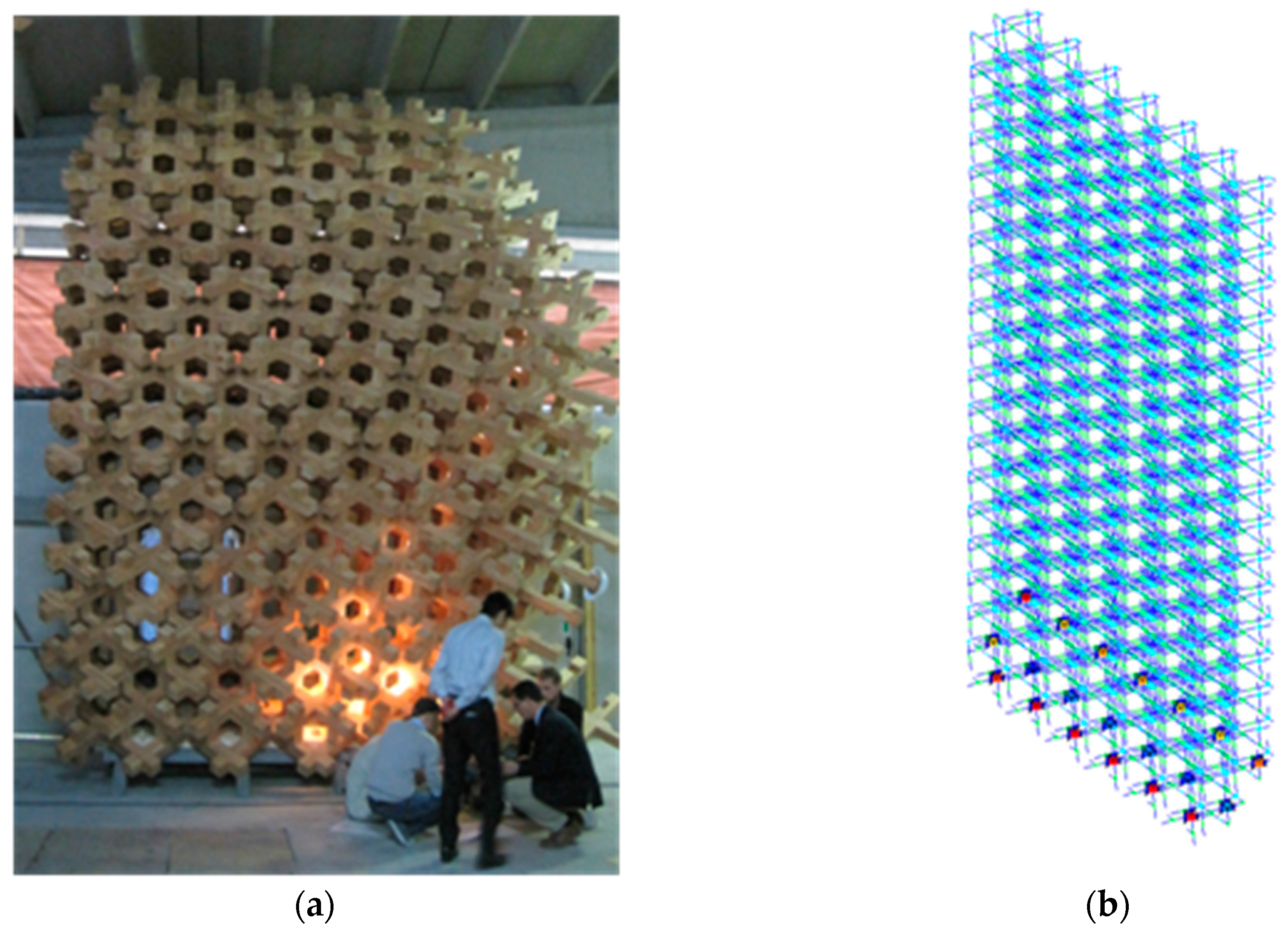
The investigated load combinations primarily regarded ultimate or collapse limit states. The category of ‘exceptional loads’ has been considered for the stability in the case of a fire event. A dynamic impact event has been calculated for the scenario of rocking instability. Further analysis for serviceability conditions has been performed. Moreover, a prototype in real scale of about 6 m was built (
Figure 3a) to define mounting phases and to check the compatibility of components and feasibility in terms of joints.
The prototype showed a natural deformation of the structure, mainly due to the machining tolerances (fixed to 1.5 mm), which allowed an inelastic yielding, experimentally quantified at about 30 mm for every 6 m of wall. The need to insert screws in some of the basement wood joints and to apply tension on them was therefore evident. Limiting the displacements and better tightening the joints was justified to facilitate the assembly phase. This choice was also useful in assessing the efficiency of the mounting system and to prepare a specific team on site. The decision to build through basic roots of the laminated wood, instead of the steel profiles, has induced a pleasant aesthetic impact and facilitated the connection of the first grid.
The protection from dynamic events, such as an impact or a seismic shock (although in a very short time exposure), involves aspects of out-of-plane rocking, like a rigid body constrained by elastic elements [
11,
12], together with the classic structural behavior due to the elasticity of the elements [
13,
14].
The structural model, with the feedback of the prototype, was done with the program PRO_SAP, modeling the highest A1.12 wall (almost 12 m high) with 18,070 beam elements obtained by dividing about 2000 elements into nine portions (i.e., in correspondence of the central wooden joints). The external constraints were 28 spherical hinges, placed in correspondence of the base of each element.
The stresses and reaction forces were generally low. The structural calculations were based on Eurocode 5, showing that the maximum stresses were largely satisfied by the corresponding strength. The maximum stress occurred for the compression perpendicular to grain, due to the chosen constructive system. Combined actions were considered for the connections with steel elements. The fire resistance was investigated with the classic method of the equivalent reduced section.
The out-of-plane rocking of the walls has been faced throughout the formulas in [
11,
12] to take into account the elastic restraint offered by the base connections. Further evaluation has been done by the biaxiality effect, given by the steel elements that fix the walls at the base: the possibility of dissipating energy, in case of impact, is influenced by the amount of axial force, evaluating them with the expressions in [
15,
16].
Subsequently, through the 3D CAD/CAM program DICAM, named Dietrich’s code (
Figure 4), a further model of the structure was generated. It was therefore possible to extrapolate the operations of the numerical control machines from the output program. It was sufficient to model four elements only. An assembling phase was simulated before transportation, given the problems of storage in situ and the presence of shorter members on the borders.
3. Production Process
All the operations and constructive treatments were carried out at the Galloppini Legnami, in Italy. Each cutting center had the task of running (on each of the four standard pieces) ten or fourteen processes, based on the presence or absence of the four diagonal notches, to obtain the position of the interlocking piece.
About 16,080 pieces were managed—instead of 15,900 initially hypothesized with the global modeling—to include imperfections and errors or tolerances. Roto-translations, playing on the mechanical arm, reached a threshold of about 160 sec per piece against 250 sec, which was firstly proposed as the default of the machine, based on the output of the mentioned Dietrich’s code. In doing so, it was possible to achieve the goal of 200 parts per day with a single machine.
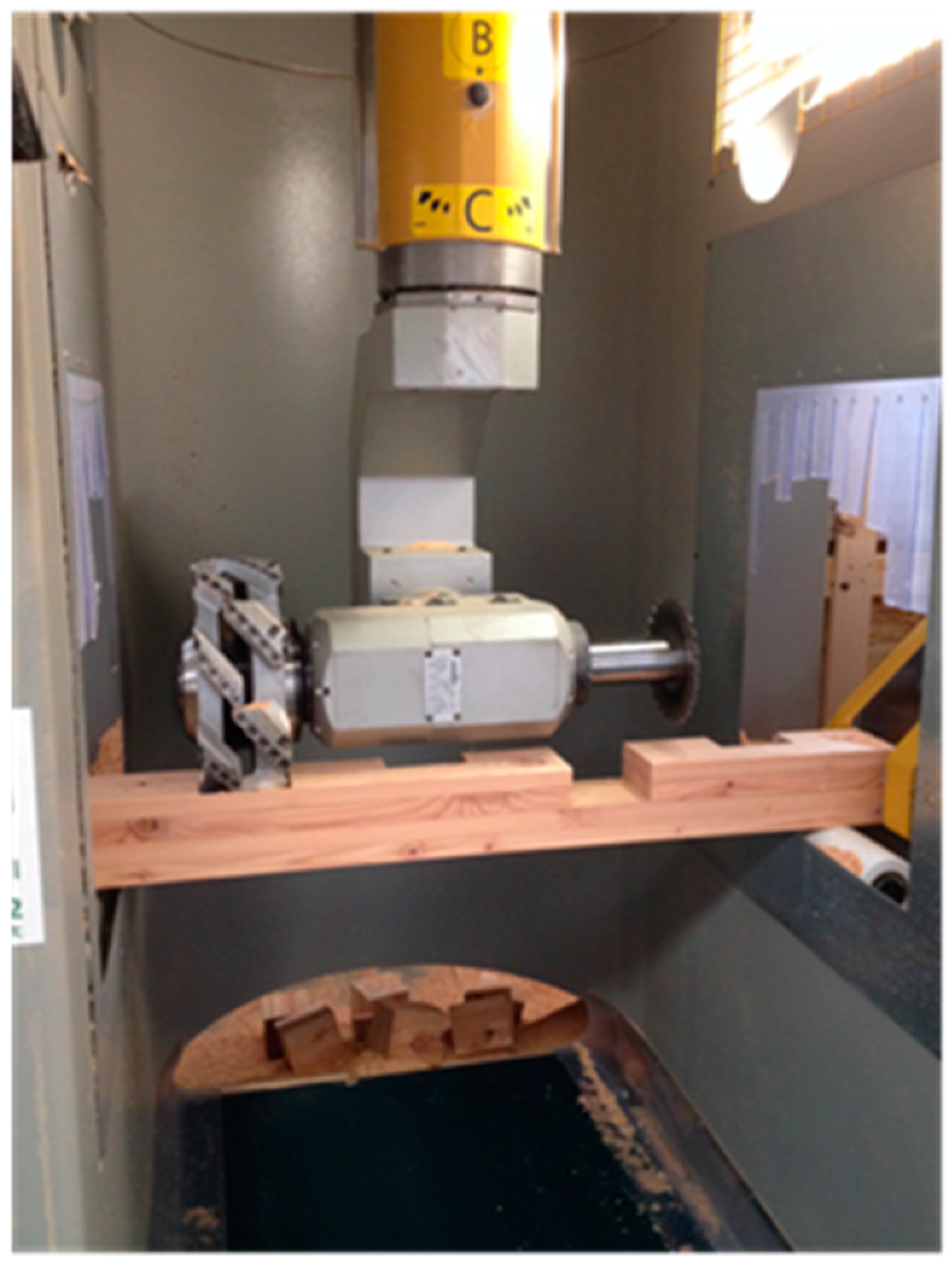
Figure 5 displays the used circular saw for cutting the wood pieces. Only in one phase is its diameter insufficient to cut the wood cross-section. That insufficiency slows down the first and the last stage by a few seconds but allows faster movements of the mechanical arm in all other stages, taking into account the lower orbit radius. The last working phase in the factory was the impregnation of the colorless, acrylic, water-based coating, with UV filters to reduce degradation and the yellowing of the wood exposed to sunlight. The main difficulty was fulfilling the client’s request for a colorless effect and, at the same time, UV protection.
Finally, a quality investment in the production process led to the reduction of pieces and operational time. The latter was a critical aspect due to the necessity of a very quick construction.
4. Mounting Phase
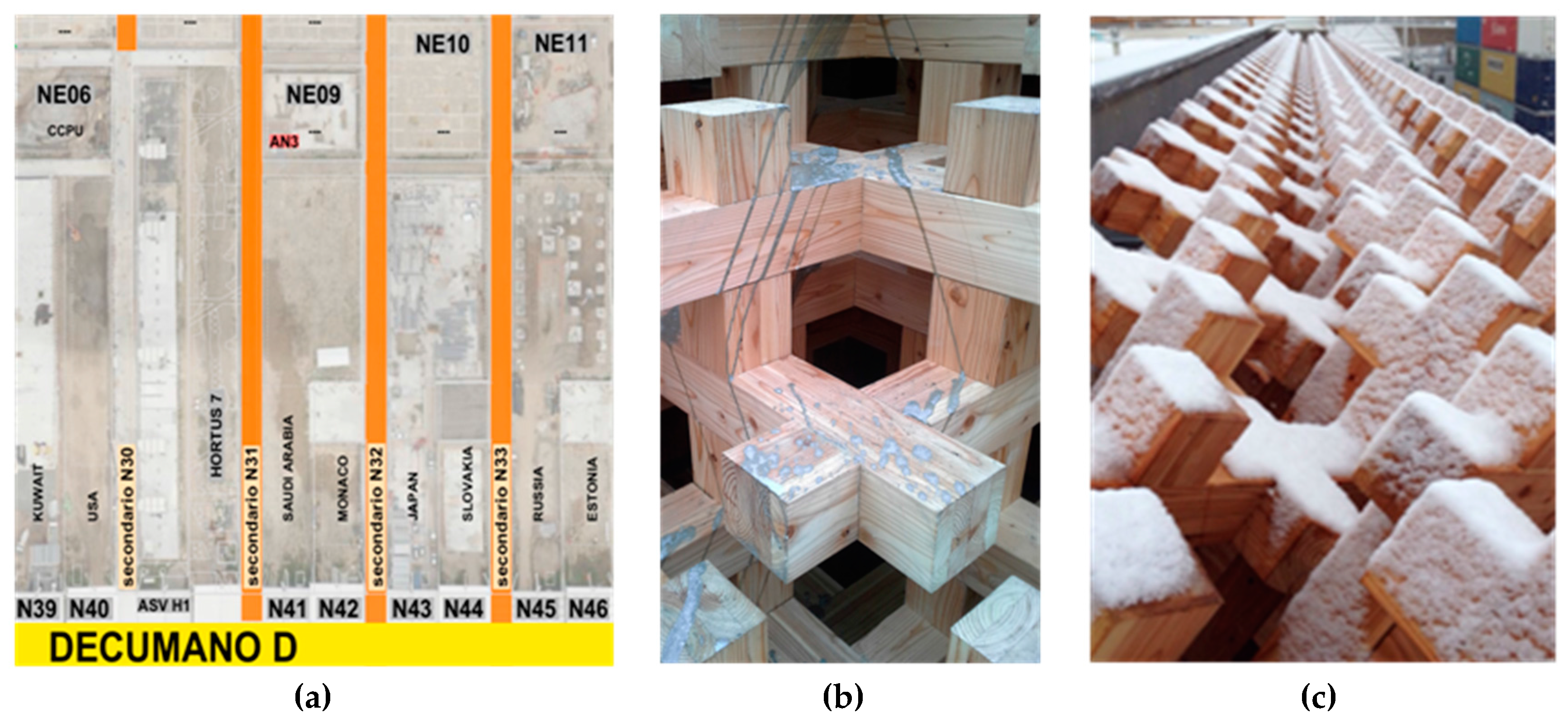
The Japan Pavilion (N43), one of the largest of Expo 2015 at 4170 m
2, was situated between the Decumano terminal, the N32 back roads, N33–N44 (the Slovak Republic), and NE10 (
Figure 6a). The construction of the walls began on December 4, 2014 (31 days later than expected) and ended (at least at the mounting level) on March 28, 2015, only five days later than expected. In accordance with the Gantt diagram, it started from behind the walls of the exhibition area before moving to the entrance once the cast of the access ramp was mature.
The yard was perhaps the most complex part of the management level, encountering a large series of problems. All the activities and movements had to fall within the perimeter of the construction site, from the barracks to the parking lots, and from the area for the storage of waste to that used for the building material. The mutual interferences were the main problem, since many companies worked together, within a short time frame and in small spaces, with obvious consequences. Finally, the N32 road, theoretically secondary, proved to be a preferential path for heavy vehicles and shuttles, with the consequent continuous lifting of dust accumulation on the walls (
Figure 6c).
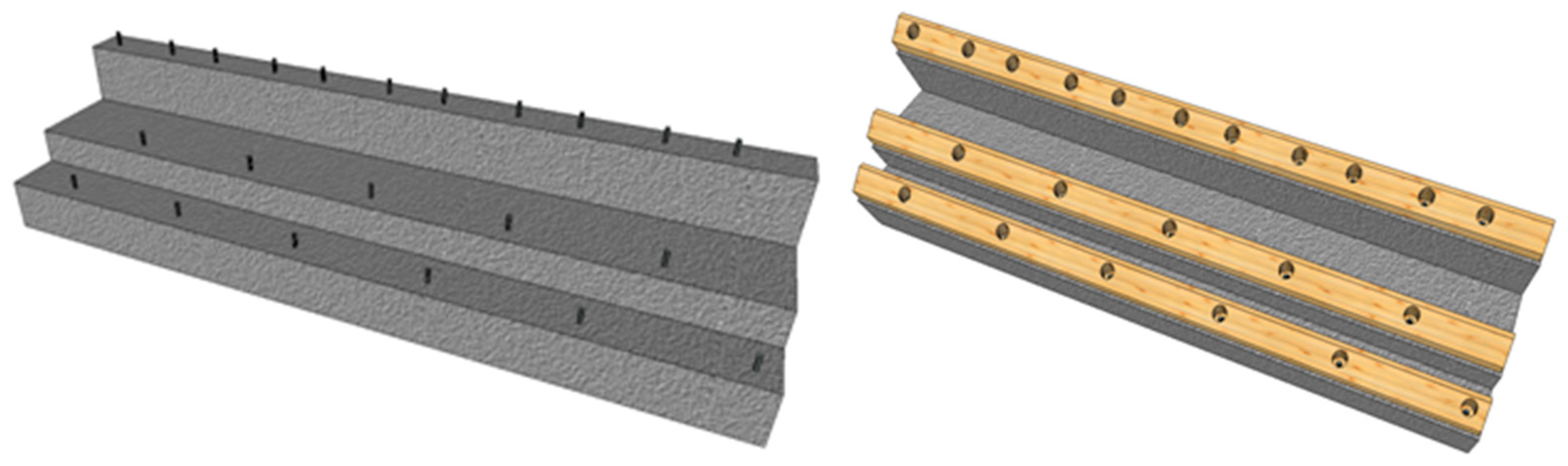
Once the protective caps were removed and after the bolts were cleaned using a screwdriver pulse, the basement was installed (
Figure 7). The horizontality of the bases was corrected with larch elements to mitigate the different tolerances between the concrete and wood. Only those wooden elements on the basement were screwed to the foundation.
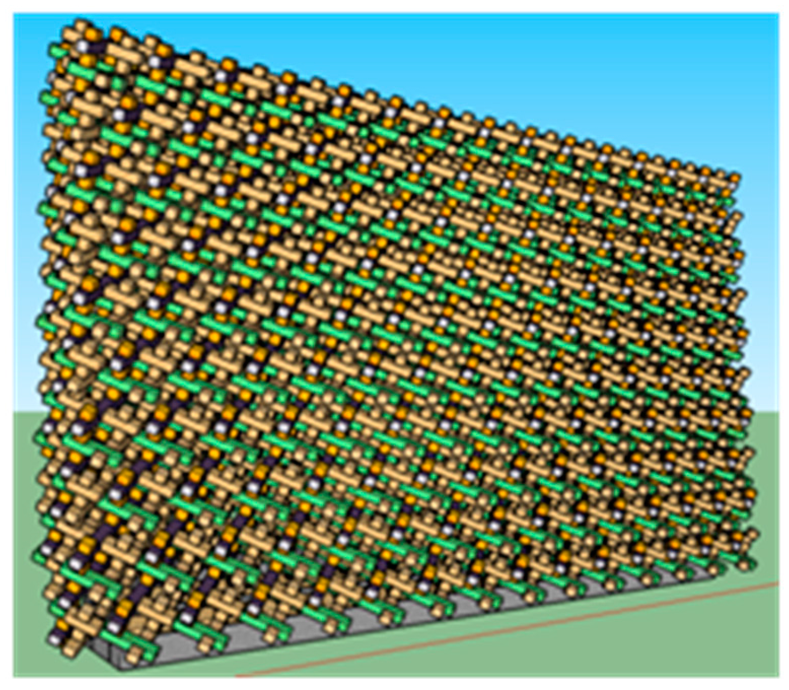
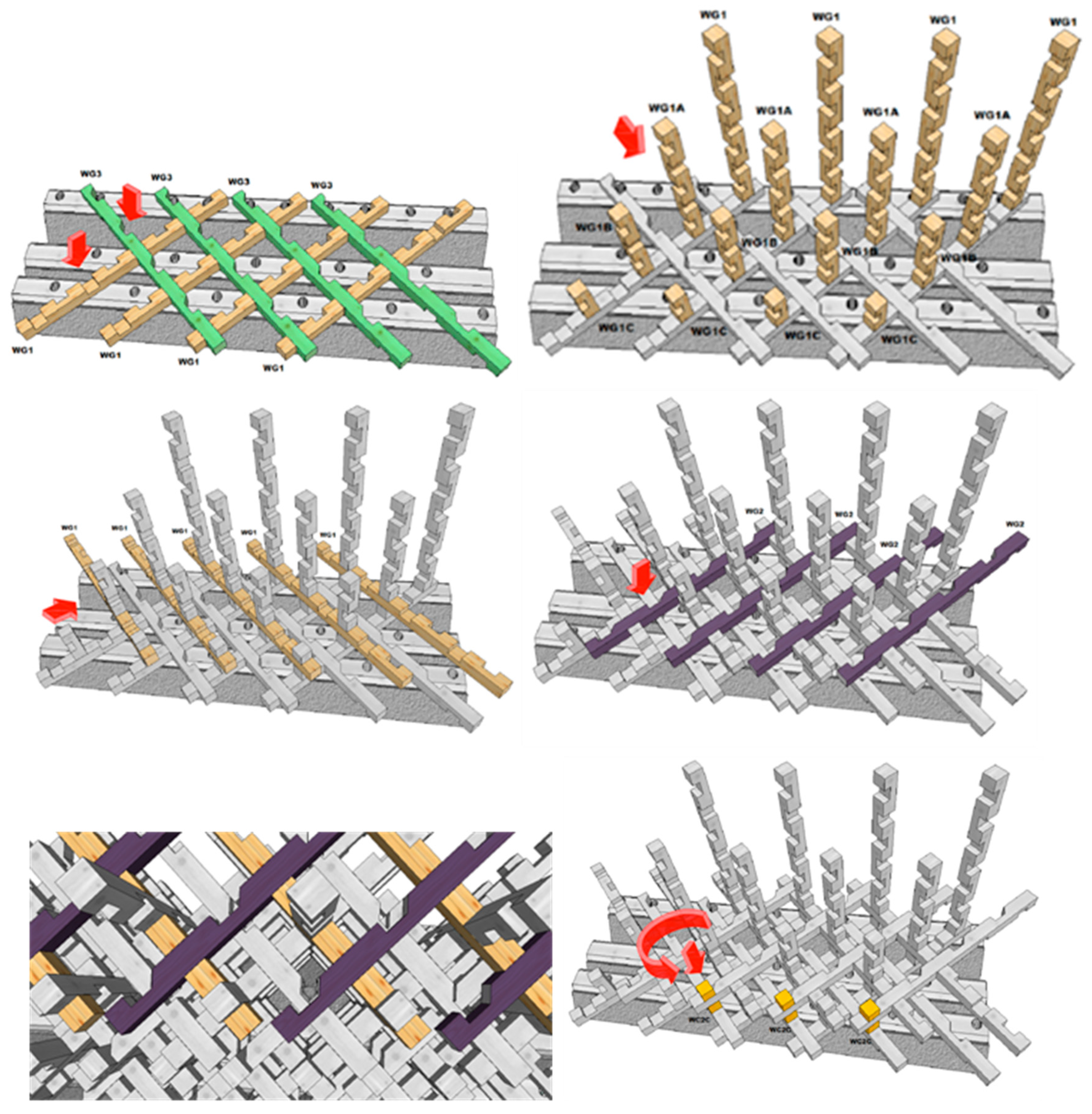
The following steps were related to the wooden structure. In
Figure 8, four different colors represent the main wall elements: WG1 (light brown); WG2 (violet); WG3 (green); WC2 (yellow). They were subdivided in three lengths: A-156 cm; B-104 cm; C-52 cm.
The construction stages followed a specific procedure (
Figure 8): the first layer, made of two crossed elements, was mounted over the basement. After, the first series of uprights were installed on it and screwed at the bases. Then, another layer of horizontal elements, labeled WG1 and WG2 in
Figure 8, were wedged in the uprights. Additional anchor elements were finally installed and rotated by 90° counter-clockwise, to allow for the interlocking of both underlying layers. This step was possible through the grooves in the pieces WG2 and WG3, which did not oppose the passage of the sharp edges of the vertical pieces.
Starting from these phases, the mounting process continued in a sequential manner (
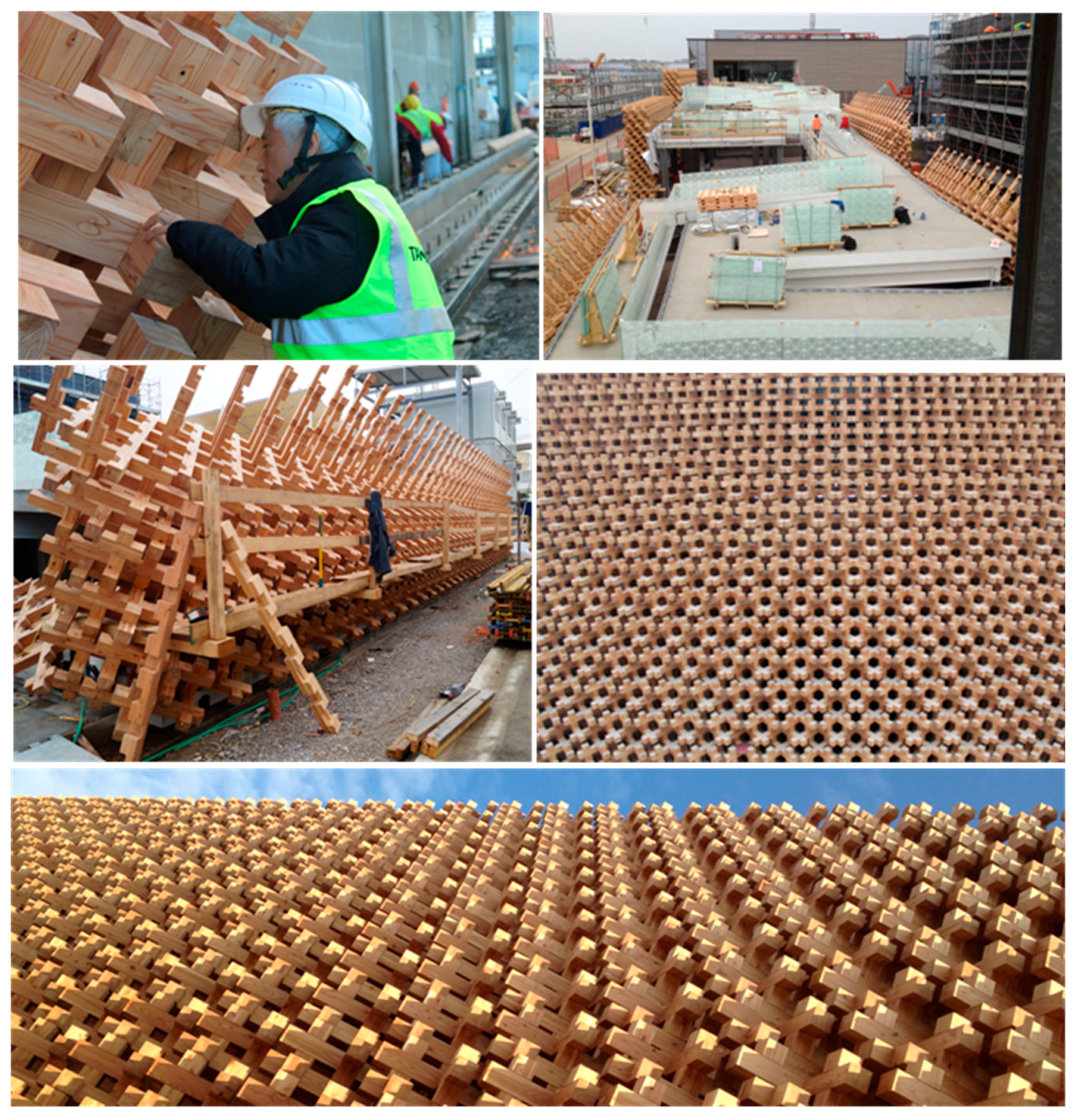
Figure 9). A maximum of eight layers could be mounted at the same time. Note that it was mandatory to complete a horizontal layer before continuing with the construction of further layers. The final result is displayed in
Figure 10.
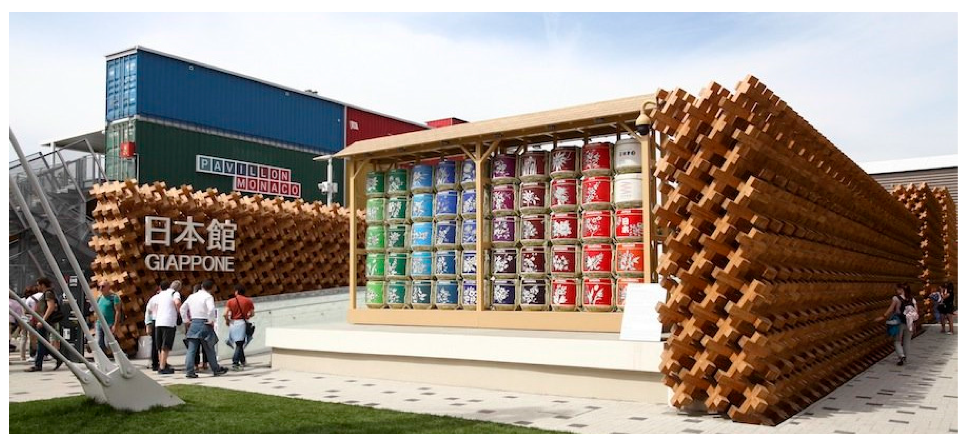
5. Conclusions
The complex geometry of the Japanese Pavilion built for Expo 2015 is investigated here, together with the mounting phases and interpretation of its mechanical behavior.
- -
Visitor Feedback. The hypnotic geometry of the Japan Pavilion captured the attention of many visitors who considered it as a must-visit at Expo 2015.
- -
Sustainability. The green economy is an intrinsic part of the laminated wood philosophy; however, in this case, the opportunity to disassemble the building to recreate it in a different location is also ensured simply by applying the reverse of the assembly process, as required by organizers.
- -
Robustness. The use of many elements, thin and lightweight, designed in three dimensions to form “the cubic units”, will achieve high resistance without increasing the mass, relying on a significant degree of hyperstaticity or redundancy. Its structural concept was only formalized recently in standards, but it has already been treated in Japanese traditions.
- -
Structural modeling. The check of the various, specifically considered, limit states showed interesting results in terms of stiffness, strength, and ability to withstand exceptional loading conditions, such as the dangerous rocking out-of-plane collapses [
17].
- -
Prefabrication. The production at the factory is perhaps one of the strongest features of this technology with a reduction to only four different basic elements to enhance the prefabrication.
- -
Assembly. The steps conceived for the realization are optimized in terms of time consumption and number of pieces; ensuring the use of the Merikomi technique is also a necessary condition.
- -
Self-supporting. An attractive property of the system is its self-supporting capacity, which does not need temporary supports until it proceeds in elevation and, indeed, allows the use of construction techniques that are very reminiscent of the scaffolding holes used for the construction of the most important medieval buildings.
- -
Transportation. Easy transport of the entire system, due to the reduced size of the single piece, allows the possibility of locating this architecture in poorly accessible areas, such as mountainous regions or town center accommodations, without a theoretical size limit.
- -
Working Phases. This experience showed that a team of at least two people is necessary to continue with the installation process and how this composition of the working groups —once the sequences of work are assimilated—is able to lay about 20 m2 of wall per day.
The entire system can be used in terms of an ecologically framed wall. In this sense, the authors suggest to couple it with natural—not load bearing—components, such as shives, cork elements, or both [
18], with the prospect of further dissemination of the described system.
Acknowledgments
Thanks to Atsushi Kitagawara who conceived the constructive system, Francesco de Pace and Andrea Costa of Galloppini Legnami for technical support and the data collected, together with the entire staff cited in the paper. Thanks to the anonymous reviewer that contributed to the improvement of the paper.
Author Contributions
Matteo Cipollini attended the constructive phases and launched the structural calculations, Elisa Bonannini contributed to historical findings and architectural aspects, Marco Cinotti revised the structural calculations, Mauro Sassu revised the entire work, and all authors contributed to the preparation of the paper.
Conflicts of Interest
The authors declare no conflict of interest.
References
- Andreini, M.; De Falco, A.; Giresini, L.; Sassu, M. Structural damage in the cities of Reggiolo and Carpi after the earthquake on May 2012 in Emilia Romagna. Bull. Earthq. Eng. 2014, 12, 2445–2480. [Google Scholar] [CrossRef]
- Giresini, L. Energy-based method for identifying vulnerable macro-elements in historic masonry churches. Bull. Earthq. Eng. 2016, 14, 919–942. [Google Scholar] [CrossRef]
- Andreini, M.; De Falco, A.; Giresini, L.; Sassu, M. Collapse of the historic city walls of Pistoia (Italy): Causes and possible interventions. Appl. Mech. Mater. 2013, 351–352, 1389–1392. [Google Scholar] [CrossRef]
- Sassu, M.; Andreini, M.; Casapulla, C.; De Falco, A. Archaeological consolidation of UNESCO masonry structures in Oman: The Sumhuram Citadel of Khor Rori and the Al Balid Fortress. Int. J. Archit. Herit. 2012, 7, 339–374. [Google Scholar] [CrossRef]
- Do Kien, Q.; Takanobu, N.; Vo Minh, T.; Yasuro, M. On the Special Earthquake Resistance of Five-Stories Timber Pagodas in Japan; Acta of Hutech University: Ho Chi Minh City, Vietnam, 2010. [Google Scholar]
- Nakahara, K.; Hisatoku, T.; Nagase, T.; Takahashi, Y. Earthquake response of ancient five storey pagoda structure of Horyu-Ji Temple in Japan. In Proceedings of the WCEE 2000, Auckland, New Zealand, 30 January–4 February 2000.
- Goldsmith, G. Principia Designae—Pre-Design, Design, and Post-Design 2014. In The Pagoda Design Space: Extending the Scope of Design; Toshiharu, T., Ed.; Chapter 5; Springer: Cham (ZG), Switzerland, 2015; pp. 61–76. [Google Scholar]
- Parent, M.N. The Roof in Japanese Buddhist Architecture; Weatherhill: Boulder, CO, USA, 1983; p. 348. [Google Scholar]
- Liang, S.C. Chinese Architecture, A Pictorial History (Dover Architecture); Fairbank, W., Ed.; Dover Publications: New York, NY, USA, 2005; p. 240. [Google Scholar]
- De Falco, A.; Giresini, L.; Sassu, M. Temporary preventive seismic reinforcements on historic churches: Numerical modeling of San Frediano in Pisa. Appl. Mech. Mater. 2013, 352, 1393–1396. [Google Scholar] [CrossRef]
- Giresini, L.; Fragiacomo, M.; Sassu, M. Rocking analysis of masonry walls interacting with roofs. Eng. Struct. 2016, 116, 107–120. [Google Scholar] [CrossRef]
- Giresini, L.; Fragiacomo, M.; Lourenço, P.B. Comparison between rocking analysis and kinematic analysis for the dynamic out-of-plane behavior of masonry walls. Earthq. Eng. Struct. Dyn. 2015, 44, 2359–2376. [Google Scholar] [CrossRef] [Green Version]
- Fujita, K.; Koshihara, M.; Sakamoto, I.; Tsuwa, I. Hysteresis model and stiffness evaluation of bracket complexes used in traditional timber structures based on static lateral loading tests. J. Struct. Constr. Eng. 2001, 5, 121–127. [Google Scholar]
- Katagihara, K. Preservation and seismic retrofit of the traditional wooden buildings in Japan. J. Temporal Des. Archit. Environ. 2001, 1, 1. [Google Scholar]
- Sassu, M. The Reinforced Cut Wall (RCW): A low-cost base dissipator for masonry buildings. Earthq. Spectra 2006, 22, 533–554. [Google Scholar] [CrossRef]
- Sassu, M. Biaxiality effect on the energy dissipated by elastoplastic base-isolators. J. Eng. Mech. 2003, 129, 607–612. [Google Scholar] [CrossRef]
- Giresini, L.; Sassu, M. Horizontally restrained rocking blocks: evaluation of the role of boundary conditions with static and dynamic approaches. Bull. Earthq. Eng. 2016, 1–26. [Google Scholar] [CrossRef]
- Sassu, M.; Giresini, L.; Bonannini, E.; Puppio, M.L. On the use of vibro-compressed units with bio-natural aggregate. Buildings 2016, 6, 40. [Google Scholar] [CrossRef]
© 2016 by the authors; licensee MDPI, Basel, Switzerland. This article is an open access article distributed under the terms and conditions of the Creative Commons Attribution (CC-BY) license (http://creativecommons.org/licenses/by/4.0/).

