2.2. Equipment for the Meausurement System
The design and construction of the test system and trials were carried out in laboratories of the Department of Agricultural, Food and Forestry Systems (GESAAF).
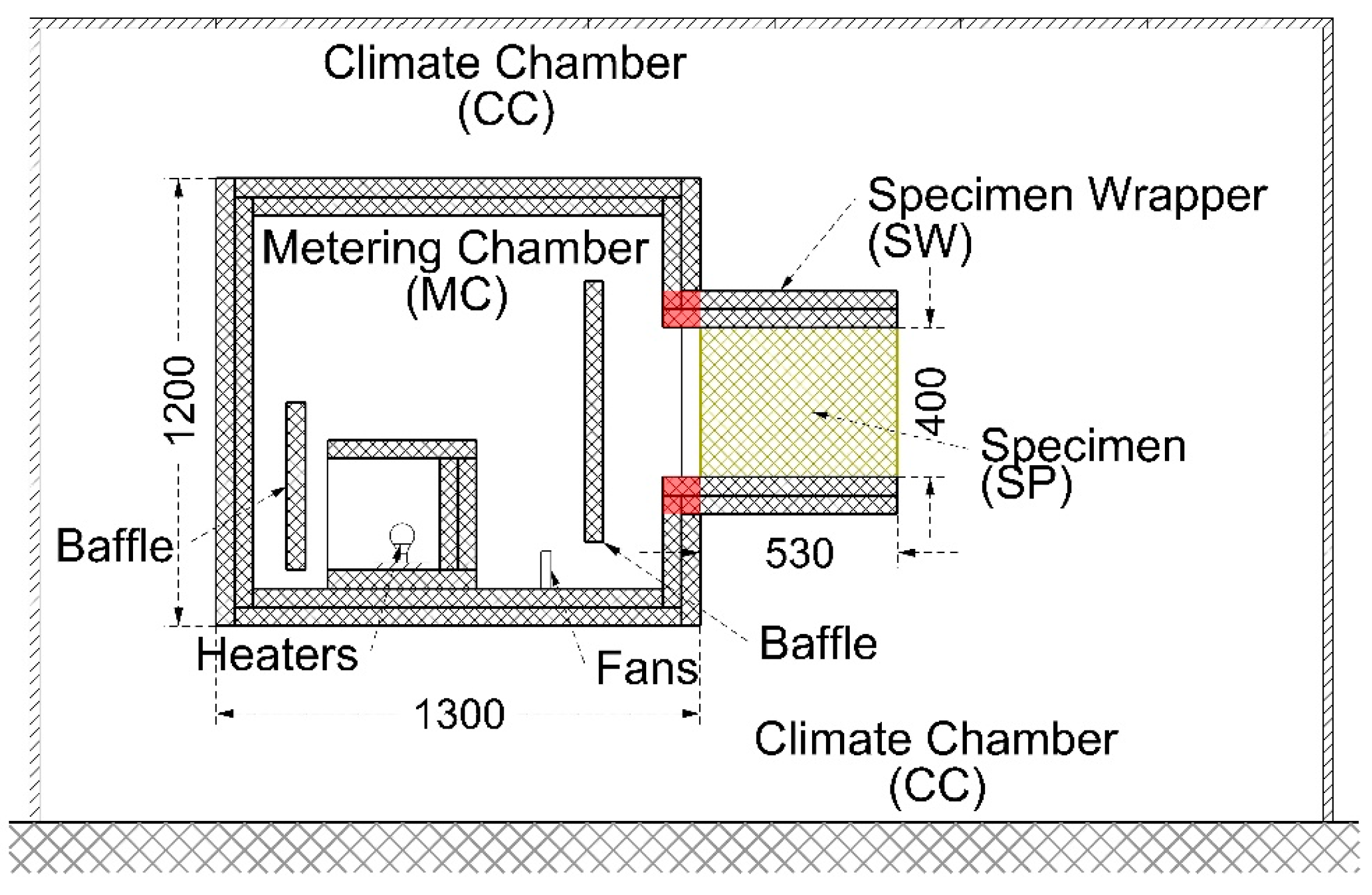
The measurement system is composed by these sub-systems: Metering Chamber (MC); Climate Chamber (CC); heaters; MC internal ventilation; CC air conditioning system; temperature measurement; air speed measurement; energy flow measurement.
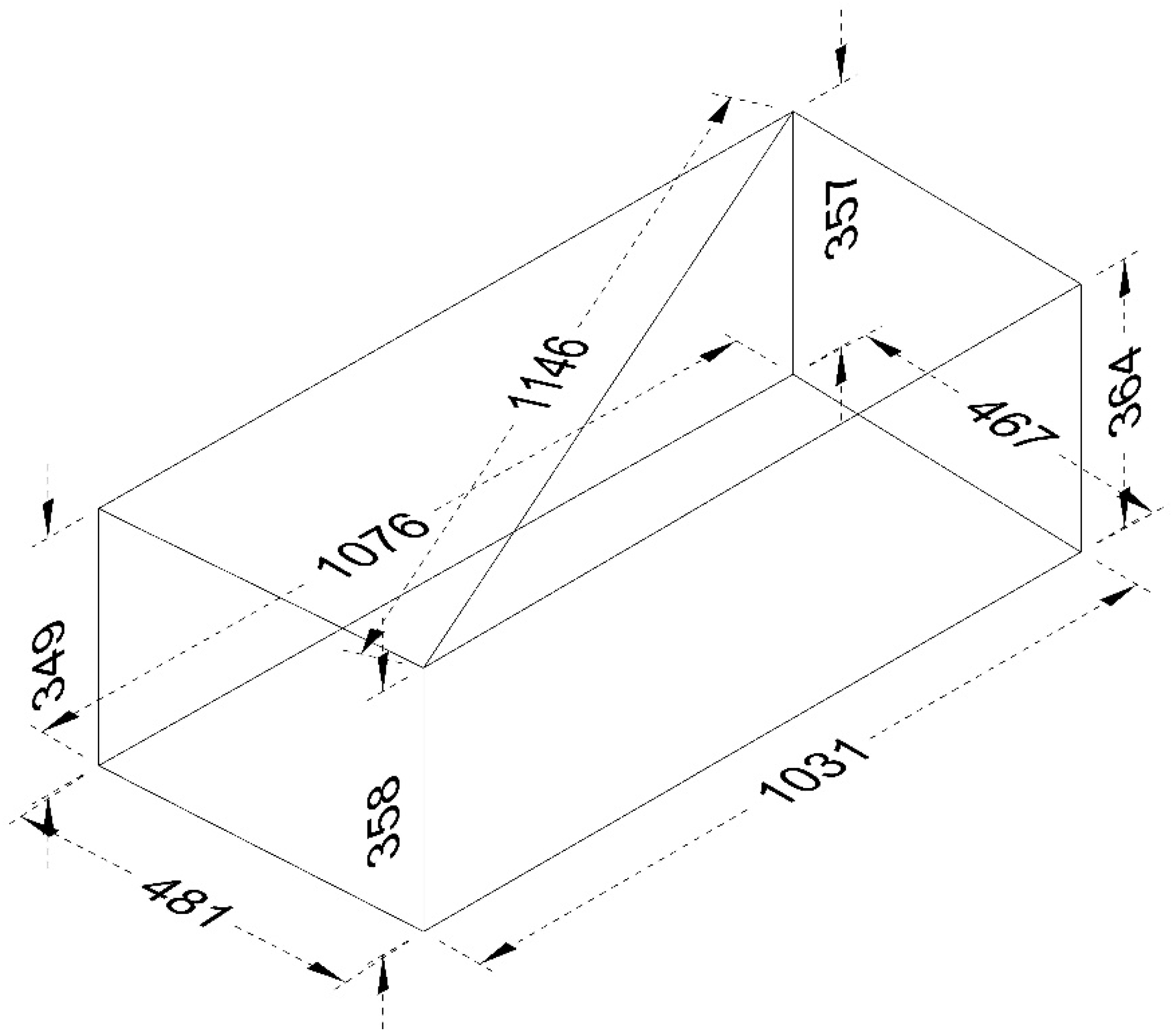
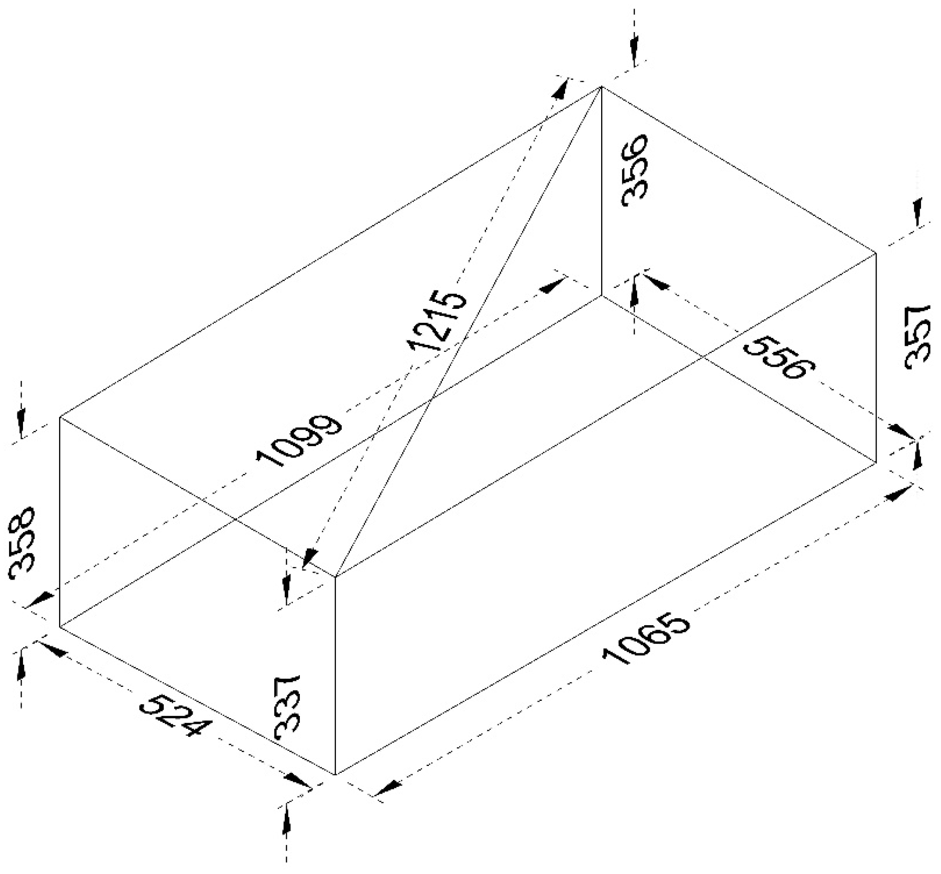
The MC has the external dimensions of 1200 × 1300 × 1800 mm
3 (
Figure 1 and
Figure 2).
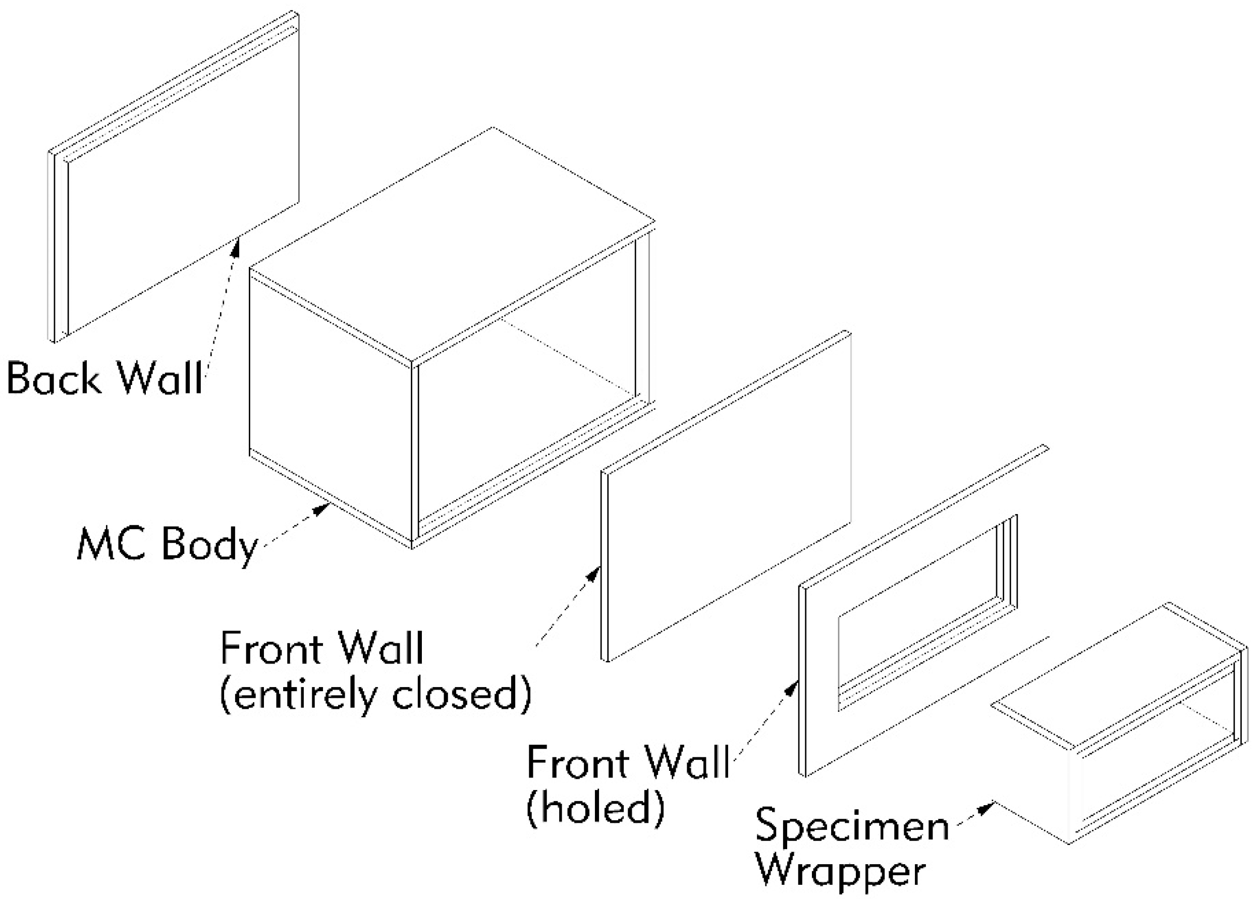
The MC (
Figure 3 and
Figure 4) is constituted by a central body, having the external dimensions of 1200 × 1200 × 1800 mm
3. The connections between the walls of the body have a labyrinthine shape, in order to reduce the loss of heat due to discontinuities.
The body can be closed by a movable flat rear wall and by a movable front wall. The front wall can be entirely closed, or provided with a hole for the positioning of the specimen. Even the connections of the body with movable walls have a labyrinthine shape.
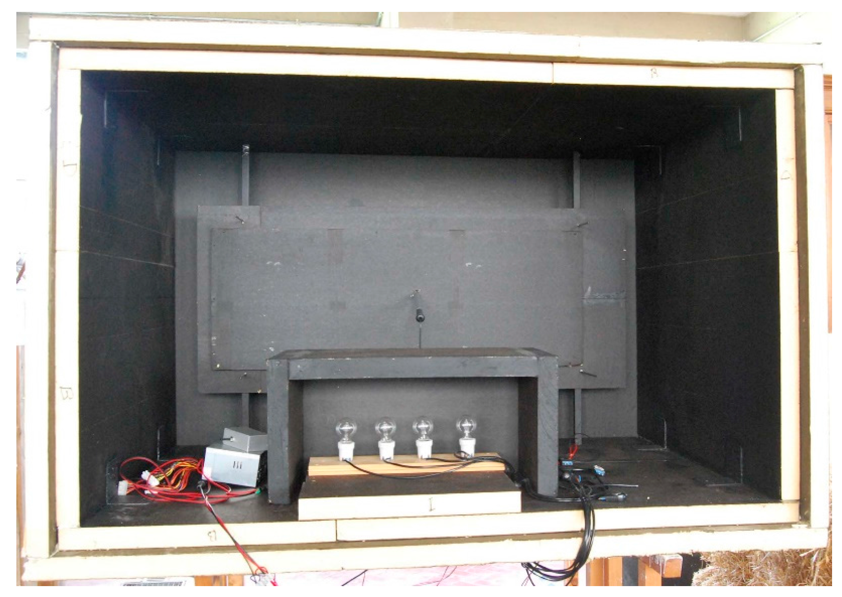
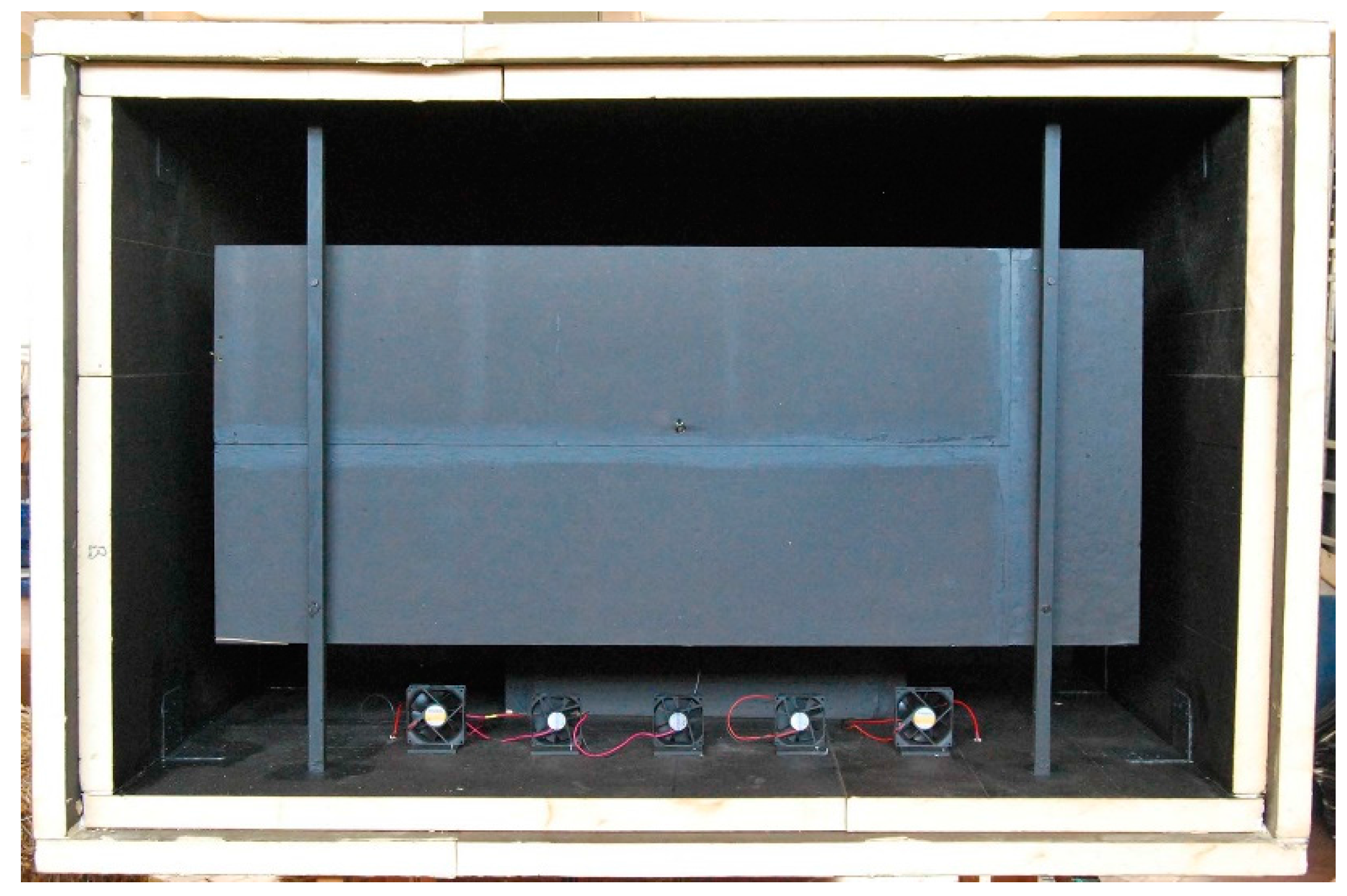
The Specimen Wrapper (SW), designed to contain the specimen, leans out of the hole of the front wall. Inside MC a baffle is placed, to direct the flow of air generated by the fans and to prevent the inner surface of the specimen being directly exposed to the heat sources.
The walls of the MC and the SW are constituted by panels of Stiferite BB, having a nominal thickness of 50 mm. The panels are coupled, such as to form a wall of nominal thickness of 100 mm, by means of vinyl adhesive. Two layers of panel joints are staggered to minimize the possibility of heat loss through them. The typical emissivity of the bituminous paper surface is ε = 0.93, higher than the minimum required by [
15] (ε > 0.80).
Stiferite BB is a sandwich panel made of an insulating component in polyisocyanurate foam, coated on both sides with bituminous paper. The mass per unit area of the 50 mm thick panel is 2.20 kg/m2, corresponding to a density of 44.38 kg/m3. The thermal conductivity declared by the manufacturer is λ = 0.028 (at the mean temperature of 10 °C, for 20–70 mm thickness). Since the thermal insulation properties of the foam materials decay over time and the date of manufacture was not indicated, the above value of λ is considered indicative.
The Climate Chamber (CC) is a closed space, in which the MC is placed (
Figure 1).
The heat is generated by a system placed inside the MC, consisting of incandescent lamps of different power. The group is enclosed in a box of Stiferite BB closed on five sides. The open side faces a baffle of the same material to reduce the heating of the walls of the MC by direct radiation (
Figure 1). The lamps can be operated individually by external control.
The internal ventilation of MC is supplied by a ventilation system composed by five computer fans, two having the rated power of 2.00 W, three having the rated power of 2.28 W.
An air conditioning system is placed inside the CC.
The surface temperature measurement system is 14 thermopiles arranged on the surfaces of the internal and external walls of the MC, of the SW, and of the specimen. One thermopile is arranged around the MC, for the measurement of the temperature of the interior of the CC. Each thermopile consists of several type K thermocouples.
The thermopiles are connected to a Pico TC08 data logger.
The measurement of the air speed is performed by means of a hot-wire probe lataOHM AP471 S2 connected to the data logger lataOHM DO9847.
The energy flow relative to heat generators and fans placed inside the MC is measured by means of a power meter (Wattmeter) PCE instruments type PCE-PA6000.
2.3. RSB Geometry and Density
The RSB is a geometrically irregular item. Its size and density can vary not only as a function of the species and varieties of cereals and of the methods of cultivation and harvesting, but also from element to element of the same origin.
To allow the actual comparison of the results of thermal tests, a measurement system of the geometry of the bales was designed. In this way, only conventional values of the dimensions and of densities were determined. However, these values are effectively comparable with each other.
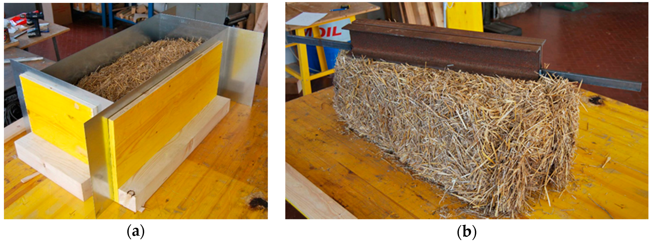
For the measurement of the plant dimensions, four pinwheel walls were made, in order to follow the trend of the four vertical faces of the bales (
Figure 5a).
For the measurement of plant dimensions, a horizontal force of 200 N to each pair of opposite walls has been applied.
For the measurement of the height of the edges, a straight edge having a mass of 24.30 kg was made (
Figure 5b).
To determine the specimen straw moisture, the Standards [
17,
18] were applied. A convection oven type Orlando Valentini PRG/M 250 and a scale Kern 470 having resolution d = 0.01 g was used.
2.5. Theoretical Observations Regarding the Process
The theoretical observations regarding the process are taken by different authors [
25,
26,
27].
2.5.1. Basic Observation
When energy Qaux is within the MC, its internal temperature becomes higher than the temperature of the CC. This latter temperature is kept constant by an air conditioning system. Continuing to input the same energy flow Qaux, when both temperatures of the MC and CC remain constant, the status of steady state has been reached. In these conditions, all the energy flow Qaux entered in the interior of the MC is transmitted, through its walls, to the CC, and it is absorbed by the air conditioning system of the CC or dispersed into the surrounding environment if its temperature is lower than the CC temperature.
2.5.2. Thermal Conductivity of the Walls of the MC
Six walls of the same material and thickness Lmc constitute the MC.
The effective area of the MC wall normal to heat flow A
mc,e,eff is given by [
15]:
where A
mc,e,in is the MC inside surface area,
is the sum of 12 MC interior edge lengths formed where two walls meet each other.
The quantity of energy flow introduced in MC, Q
aux is given by [
15]:
where Q
h is the energy flow introduced by heaters, Q
f is the energy flow introduced by fans.
Applying Fourier’s law, the thermal conductivity λ
mc,eff of the material of the walls of the MC, in the specific temperature range, can be determined:
where t
mc,in is mean temperature of the internal surfaces of the walls of the MC, t
mc,out is mean temperature of the external surfaces of the walls of the MC.
2.5.3. Thermal Conductivity of the Specimen
In the front wall of the MC there is an opening, from which a rectangular tube protrudes, named Specimen Wrapper (SW), suitable to contain the RSB to be tested. The four walls of the tube are made of the same material of the walls of the MC mentioned above.
The energy flow running through the specimen Q
sp is given by [
15]:
where Q
mc,o is the energy flowing through the walls of the MC, Q
fl is the energy flowing through the walls of the SW.
In order to determine the energy flowing through the walls of the MC (Q
mc,o), it is necessary to know the effective net area of the MC wall (A
mc,o,eff) normal to heat flow, which is given by:
where A
mc,o is the area of the opening, plus the surface, facing towards the interior of the MC of the zone highlighted in red in
Figure 1.
Applying Fourier’s law and knowing the thermal conductivity λ
mc,eff of the material of the MC walls, in the specific temperature range, it is possible to determine the energy Q
mc,o flowing through the walls of the MC:
where t
mc,o,in is the mean temperature of the internal surfaces of the walls of the MC, t
mc,o,out is the mean temperature of the external surfaces of the walls of the MC.
In order to determine the energy flowing through the walls of the SW (Q
fl), it is important to know the effective net area of the SW wall (A
fl,eff), normal to heat flow. It is given by the relation [
15]:
where A
fl,in is the internal area of the SW, minus the surface, facing towards the interior of the SW, of the zone highlighted in
Figure 1;
is the sum of 4 SW interior edge lengths formed where two walls meet each other, minus the lengths of the edges in correspondence of the zone highlighted in red in
Figure 1.
Applying the Fourier law and knowing the thermal conductivity λ
mc,eff of the material of the SW, in the specific temperature range, previously determined, it is possible to determine the energy flow (Q
fl) flowing through the walls of the SW:
where t
fl,in is the mean temperature of the internal surfaces of the walls of the SW and t
fl,out is the mean temperature of the external surfaces of the walls of the SW.
Applying (4), the value of the energy flow passing through the specimen, Qsp, can be obtained.
Applying the Fourier law, the value of the thermal conductivity λ
sp of the specimen relative to the actual test conditions can be obtained:
where L
sp is the length of the specimen in the prevailing direction of the energy flow, t
sp,1 is the mean temperature of the hot surface of the specimen, and t
sp,2 is the mean temperature of the cold surface of the specimen.
2.6. Main Simplifications
In addition to those suggested by the [
15], the most significant simplifications introduced are the following:
a. Fourier’s law
The Fourier’s law in its one-dimensional (
) form is used (see
Table 1):
For two points at constant temperature, at a distance Δx (see
Table 1):
b. Geometry and density of straw-bales and of the specimen
For this purpose, the system described in
Section 2.3 was designed and operated.
c. Energy flows
The energy flow that occurs between the MC and CC through the area marked in red in
Figure 1 is very complex. In this zone, the heat exchange between the MC and CC is not direct, but occurs through the adjacent zones of the walls of MC. The definition of the way in which this heat exchange occurs requires a dedicated study, which will be performed in a second step of the research. In this work, considering that the surface of the zone in question is relatively small compared to the total, the effects of this singularity are neglected.
d. Air flows
The specimen shall be sealed relating to exchanges of air with the MC and the CC. For this purpose, two surfaces in contact with MC and with CC were closed by means of a film of Linear Low-Density Polyethylene (LLDPE), having a thickness of 23 µm and thermal conductivity of 0.33 Wm−1·K−1.
The connections of the detachable walls with adhesive tape were sealed.
e. Effective areas
The Equations (1) and (7) are derived by applying to this particular case the relation (A3.2) of the ASTM [
15], which is given for a chamber having five walls, that is eight edges. In this case, there are respectively 12 and 4 edges: relations are calculated using the corresponding values of the two cases.


