1. Introduction
The building sector is one of the most influential in the world economy, but is also characterized by its high impact on energy consumption. In the European Union (EU), energy consumption of buildings accounts for over 40% of the final energy consumed in the EU, of which residential buildings are responsible for 63% of total energy consumption in the building sector [
1].
To promote energy efficiency and sustainability in this sector, it is fundamental to reduce the energy consumption of buildings, especially in their operational stage, since this represents 80%–85% [
2] of total energy consumed during their life cycle. For this large percentage, the main contributions come from cooling and heating, 55% to 74%, depending on the climatic region [
3] and hot water production. Therefore, it is imperative to develop and/or optimize constructive solutions and methods that offer clear advantages in reducing the energy costs of buildings during this stage of their life cycle.
Over the last few years, alternatives to the traditional constructive method have emerged and proliferated. Given the advantages of metallic structures along the entire life cycle of buildings, the use of steel as a structural and non-structural construction element has intensely increased in the construction sector. The LSF system, characterized by using cold-formed steel profiles and pre-fabricated non-structural panels, is an example of this new and growing trend.
Despite the obvious benefits of LSF construction, if not correctly designed and built, thermal bridges created by the intensive use of steel can penalize buildings’ exterior envelope thermal performance and, consequently, their overall energy efficiency. Given this, in the recent years, efforts and methodologies have been gathered to evaluate and to improve this type of structures thermal behaviour, attenuating the effect of thermal bridging in the exterior envelope.
Unlike traditional construction, which in addition to the thermal insulation incorporates materials that have considerable thermal resistance, as ceramic bricks, LSF buildings’ thermal performance is highly dependent on the applied thermal insulation. Gervásio et al. [
4] performed a parametric study to analyse the influence of insulation on the energy balance for an LSF building located in Portugal (mainland). This study shows that decreasing the insulation in: 30 mm of polystyrene to 0 mm and 140 mm of rock wool (RW) to 70 mm, in the exterior walls; 140 mm of RW to 70 mm in the roof and terrace—increases by 22.7% the annual energy needs of the building. The same authors also conclude that the annual energy needs are substantially more sensible to the decreasing of thermal insulation than to the increasing of this element. Therefore, applying insulation in buildings must follow some criteria and solid designing, to avoid investing in an asymptotic decrease of the annual energy needs, prejudicing the insulation cost-effectiveness ratio.
Nowadays, it is no longer enough to minimize the operational energy of buildings, for example, by increasing in an exaggerated way the thermal insulation of the exterior envelope to reduce heat losses. There is a need to simultaneously consider and find an optimal compromise between the operational and the embodied energy while also considering the cost-effectiveness of the several building components available. Thus, it is necessary to take the most advantage of thermal insulation materials, reaching high levels of buildings energy performance, using, however, the fewest possible resources (and/or the eco-friendliest ones).
In this paper, the LSF constructive system is analysed, focusing in the effectiveness of thermal insulation regarding its position in facade walls. In a first stage, a brief approach to cost effectiveness importance in the construction sector is performed. Some essential concepts in this paper scope are also explained, as the concept of embodied and operational energy. Next, the three types of LSF construction depending on the thermal insulation position (cold, warm, and hybrid construction) studied in this paper are presented and illustrated. The main advantages and disadvantages of each construction type are also explained. As background to this study, several advantages of LSF system are presented. Some drawbacks of this type of construction will be mentioned as well, in the scope of its thermal behaviour and focusing on the thermal bridges problem.
A numerical study is presented in order to: (i) evaluate the influence of the thermal insulation position on its effectiveness, when applied in three types of LSF facade walls; and (ii) study the influence of thermal bridges instigated by the steel frame on its overall thermal performance. This thermal behaviour evaluation is also analysed under the Portuguese Thermal Regulation for Residential Buildings (REH) [
5]. The obtained thermal transmittances (U-values) are compared with minimum requirements imposed by this regulation with regard to facade walls.
It should be noticed from the beginning that the main goal of this study aims to evaluate the influence of thermal insulation position in a single LSF facade wall thermal performance. In this line of thought the heat flow at the junctions where the facade wall meets other building elements (e.g., slabs, ground floor, walls, roof, etc.) is not under analysis.
2. State of the Art
2.1. Thermal Insulation Effectiveness
In an era marked by a deep economic and environmental crisis, measures and studies that reduce the monetary and ecological costs in the construction sector proliferate. As a consequence of this crisis, the challenge of the real estate market is not only to build buildings with high energy performance but also to do so by implementing the most cost effective solutions. Under this concern umbrella, in Europe, the most recent updates to the directive on the energy performance of buildings [
6] introduce two basic concepts: Cost-optimal energy, focused on monetary costs and almost zero-energy buildings (nZEB), focusing on the energy performance of buildings and the use of renewable energy produced on site. Studies in which these two concepts are articulated have emerged, such as the one developed by Ferreira et al. [
7].
Regarding this, nowadays, measures to improve the energy performance of buildings should be seen as an investment, on which it is intended to make a profit and as soon as possible. It is no longer enough to know only the thermal characteristics of the materials/systems to be applied in buildings, the effectiveness of their performance in the intended application must be known and evaluated as well. From this point of view, it is essential to develop tools and guides that help engineers and architects to select the most cost effective solution for the purpose under study.
Due to the economic costs associated with its application and the importance in the buildings’ thermal performance, a smart use of the insulation in new buildings or rehabilitations has been a subject of considerable interest and research. Hasan [
8] and Gustafsson [
9], based on the life-cycle cost analysis, studied the optimization of the amount of thermal insulation to be applied in buildings. Optimizing the applied insulation thickness to walls in function of other constructive elements, walls’ orientation or building shade level are also studied subjects, as the work performed by Derradji et al. [
10], Ozel [
11], and Wati et al. [
12], respectively. The number of insulation layers in the wall and their arrangement is also considered in order to optimize walls’ thermal performance, considered by Al-Sanea and Zedan [
13] in a numerical study.
From the consumers’ point of view, the application of thermal insulation represents an initial cost that could reach large sums. For this investment to be profitable, the amount saved on the buildings’ energy bill over its lifetime must necessarily be higher than this initial investment. In this sense, a smart use of the insulation is essential to minimize the life-cycle cost of any building and anticipate as much as possible the return on the initial investment.
Extrapolating this line of thought to LSF buildings, it is necessary to characterize the insulation performance under the umbrella of the variety of constructive solutions that this constructive system allows. While designing this type of structures, there are some questions related to the thermal insulation that designers must address, such as insulation position, insulation thickness, number of layers of insulation, type of insulation, etc. Given this, it is of vital importance to know/characterize the difference in the LSF facade walls’ thermal performance regarding the insulation position in order to optimize its performance.
2.2. Embodied and Operational Energy
When evaluating the total energy associated with a product and in particular with a building, it is possible to distinguish two types of energy: embodied energy and operational energy. In low energy efficiency buildings, the embodied energy share corresponds to only 10% to 15% of operational energy [
14]. However, as the energy efficiency of buildings increases, reducing the operating energy, embodied energy share can assume a prominent position.
To promote sustainability in the building sector, the evaluation of the total energy consumed during the buildings’ life cycle is essential, in spite of limiting the analysis to the operational energy. According to Gervásio et al. [
4] two major factors contribute to the sustainability in building sector: material efficiency and energy efficiency. The same author also refers that often, to reduce operational energy needs of a building, more insulation material is used, leading to a trade-off between embodied and operational energy, which must be considered.
It is no longer enough to minimize the operational energy of buildings; finding the optimal compromise between operational and embodied energy is crucial. To fulfil this, taking the insulation as an example, it is necessary to take advantage of these materials to the greatest extent, reaching high levels of building energy performance, using, however, the fewest possible resources (and/or the eco-friendliest ones). A smart use of thermal insulation is, therefore, indispensable, and engineers and architects must maximize these materials’ effectiveness.
3. Light Steel Frame Constructive System
3.1. Classification of Light Steel Frame Elements
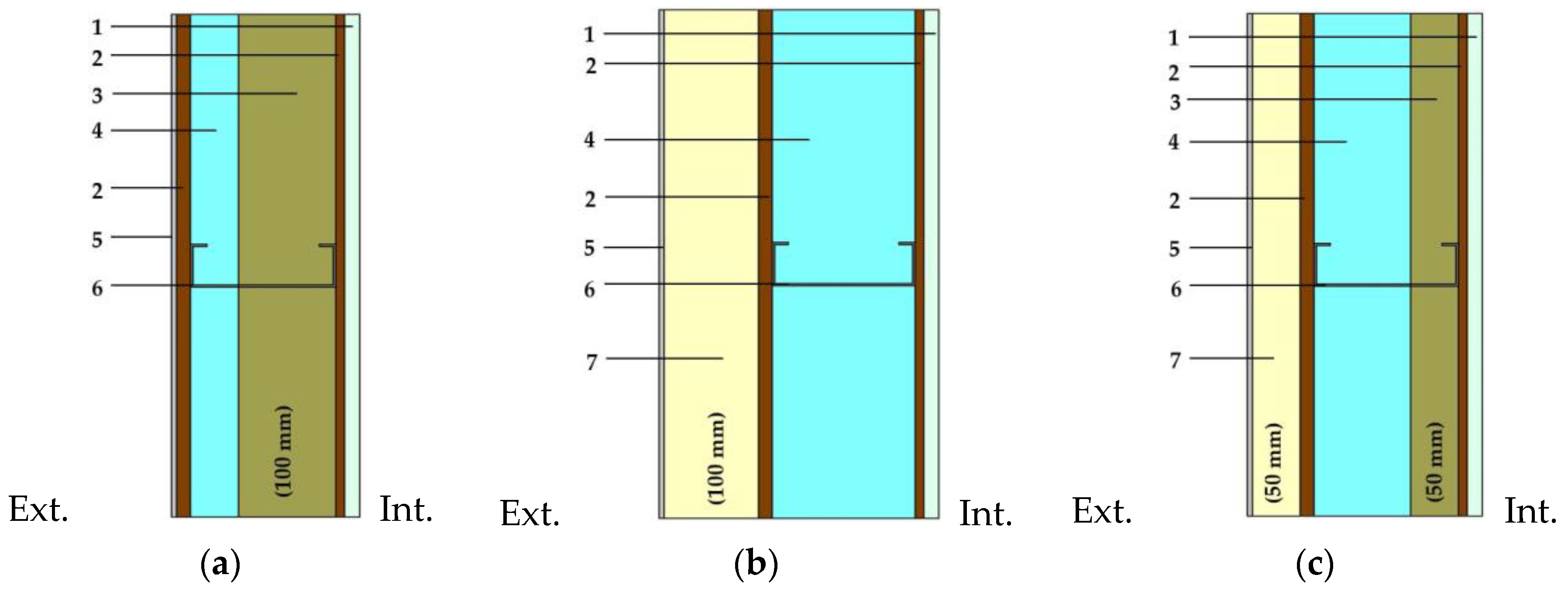
LSF construction elements, for example, facade walls, can be classified into three typologies, depending on the position of the thermal insulation.
Figure 1 illustrates these typologies. In addition to the thermal insulation, some of the most common components of LSF facade walls can be seen in the same figure: gypsum boards; rock wool (RW); oriented strand board (OSB); expanded polystyrene (EPS), usually incorporated into the external thermal insulation composite system (ETICS).
In
Figure 1 all three wall examples are presented with the same insulation thickness (100 mm). In the next chapters of this paper these three typologies will be evaluated regarding their thermal behaviour. The total insulation thickness of each wall type was studied in a range from 25 mm to 150 mm, being represented in
Figure 1 the solution corresponding to the 100 mm model. Considering this range of insulation thicknesses the corresponding U-values of the facade walls will be analysed and compared within each wall typology and between typologies as well.
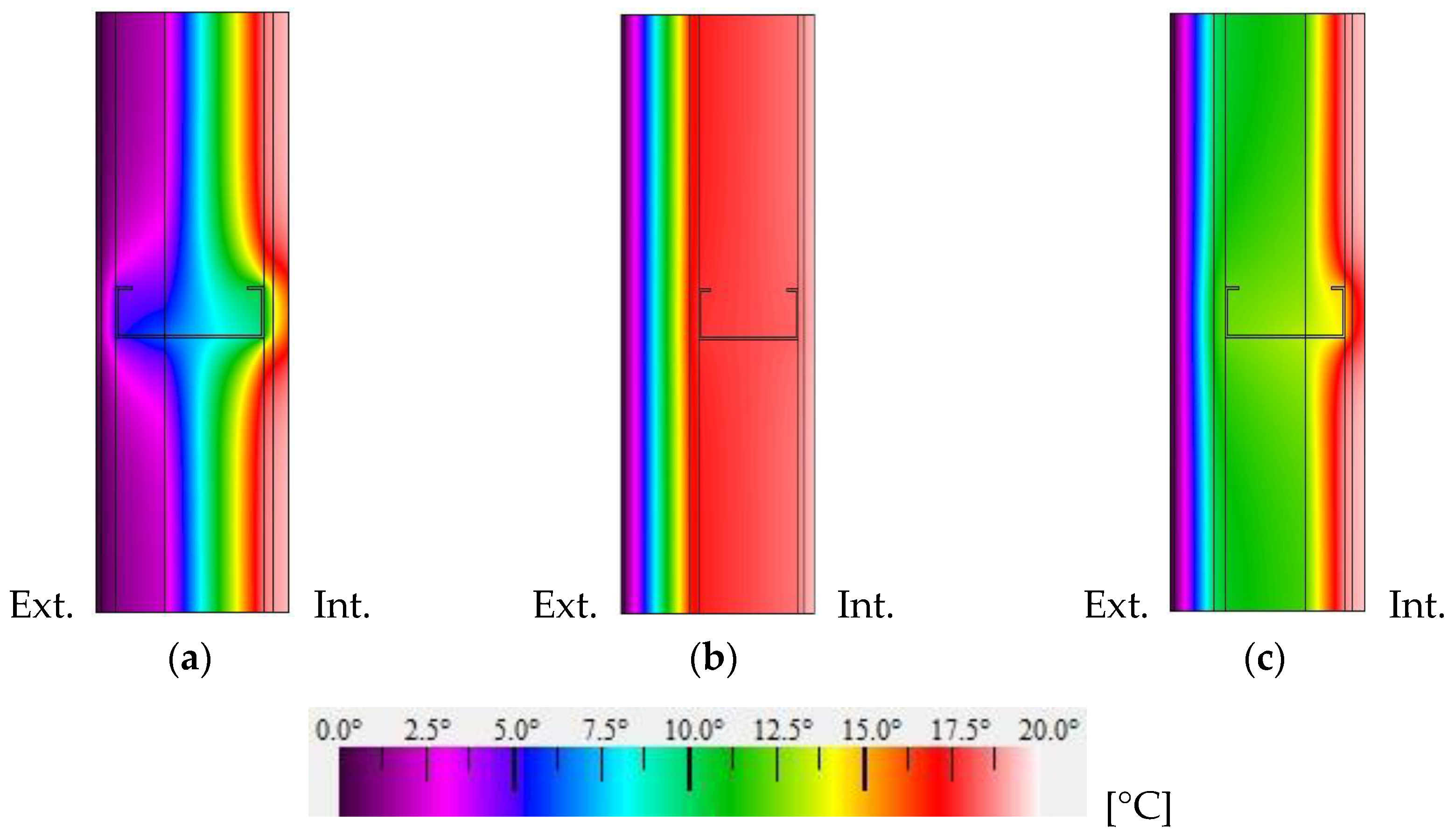
Figure 2 displays the temperatures distribution along the cross-section of the three wall types shown in
Figure 1. In
Figure 2 boundary conditions were set for external and internal environment. An external temperature was set equal to 0 °C and 20 °C for the internal temperature. The convective surface heat transfer coefficient was set according to EN ISO 6946 [
15] for a horizontal heat flow, namely h
e = 25 W·m
−2·K
−1 and h
i = 7.69 W·m
−2·K
−1 for the external and internal environment, respectively.
In cold construction (
Figure 2a), all of the thermal insulation, generally flexible (acquired in rolls), is placed inside the wall air cavity, within the thickness of the steel frame, being pierced along its thickness by it. This type of construction is not recommended for cold climates because of its poor thermal and hygrothermal performance when compared to the other types of construction, as it can be seen in
Figure 2, comparing the U-values of the three different walls with the same amount of thermal insulation.
In addition to this lower thermal insulation effectiveness, cold construction presents a higher risk of interstitial condensation, due to the low temperatures that can be registered inside the walls, especially in the steel studs and their vicinity, as illustrated in
Figure 2a. Additionally, the low internal superficial temperatures, which can be registered along the area of the steel studs and their vicinity, can be critical in the appearance of pathologies visible inside the buildings, as the phenomenon called “ghosting”, which represents wall staining on cold superficial areas.
In complete contrast to cold construction, warm construction (
Figure 2b) arises, characterized by the application of the entire thermal insulation outside of the steel framing. This constructive typology maximizes the thermal insulation potential, by reducing the U-value of the facade walls and minimizing the risk of interstitial and superficial condensations. Placing the insulation outside the steel framing makes it easier to apply a continuous layer of insulation.
In addition to these advantages, placing a continuous non-fibrous layer of insulation outside the steel frame also increases the building airtightness. In a study developed by Thorsell and Bomberg [
16] about frame-walls, they show that air ingress into the wall cavity has a significant effect on the thermal performance of walls.
In spite of the evident advantages of the warm construction, placing the thermal insulation in direct contact with the exterior environment conditions and climatic cycling can accelerate the degradation of its integrity and thermal performance if not considered or well designed. Thus, there is a need to evaluate not only the initial performance of materials but also the field performance as affected by factors such as aging of materials, possible cracks, and substrate degradation [
17].
As an intermediate solution between the two above, the hybrid construction (
Figure 2c), is characterized by having insulation material outside and between the steel frame. In this type of construction, the greater the thermal insulation thickness placed outside the steel frame, the better the thermal and hygrothermal performance of the facade walls.
3.2. LSF System Advantages
Due to their lightweight nature, construction with cold-formed profiles were first used in localized components as partition elements of the inner space or roof systems [
18]. LSF has become increasingly popular in small and medium-sized residential buildings, offering some distinct advantages over traditional construction in such fields as sustainability, cost-effectiveness, constructive process, and safety at work. As a consequence of this popularity increase, the number of companies specialized in this type of construction has been increasing, leading to more competitive prices [
3].
Regarding the components and the construction process, there are some obvious advantages: steel profiles have reduced mass and simultaneous high mechanical resistance, facilitating transportation and assembly; system suitable for industrial production, contributing to a more efficient building process [
19] and allowing greater quality control and mass production; metallic profiles are not sensible to moisture or biological activity, being safe against volumetric variations or degradation of its resistant properties; high architectural flexibility; the LSF system is a “dry” construction, therefore the risks of moisture-related pathologies are reduced or mitigated; and increased safety and health at work due to the low mass of the constructive elements and facilitated assembly. LSF system can easily incorporate various types and configurations of thermal insulation resulting in sustainable energy-efficient buildings.
In the economic field, the LSF constructive system also offers significant benefits, mainly due to the blatant reduction of the edification periods, as well as the savings in labour required and the high durability of the employed materials. As it is a lightweight construction system, the foundations may be lighter as well.
The sustainable character of this type of construction also deserves to be highlighted. Steel is a material that has near 100% recyclability and reuse rates, enabling a sustainable life-cycle end for most construction and demolition waste. When compared with traditional construction, this type of construction also allows a reduction of raw materials, as well as a lower production of waste and disturbance caused by the work site.
In a social and urban scale, LSF has the potential to construct high comfort conditions residences for low-income families as well as play a major role in urban transformation projects or in places where a fast and economical residential construction is needed [
18].
3.3. LSF System Possible Drawbacks
This type of construction, although offering great advantages and a huge potential in the pursuit of sustainability, may presents some disadvantages regarding its thermal behaviour, essentially caused by the high thermal conductivity of the steel, which can lead to significant thermal bridging and penalize the thermal resistance of the buildings' envelope. It has been demonstrated that ignoring the effect of heat transfer through the steel structure can lead to an over-estimate of thermal resistance by up to 50% [
20].
Additionally, De Angelis and Serra [
21], in a study involving a double cold LSF frame wall filled with mineral wool, concluded that without considering the metal frame, the U-value is greatly underestimated, reaching differences by up to 74% when compared with the same wall without the studs. The same author also concludes that evaluating the LSF walls’ thermal performance requires more complex and detailed analysis that the one required for masonry constructions.
In this sequence, evaluating the influence of the steel structure in LSF walls is vital to study the real thermal behaviour of those elements. In spite their relevance steel frames inside closings are usually not considered in hourly numerical thermal simulations of steel-framed buildings [
22].
Thermal bridges originated by steel studs, if not properly addressed can significantly penalize the energy performance of any LSF buildings, increase the energy consumption and associated costs during its operational stage. In addition to this increased consumption, localized heat losses may also affect the buildings’ hygrothermal performance as well, leading to construction pathologies, degradation of the building elements, reduction of indoor air quality, and surface and interstitial condensation phenomena. This aspect is particularly relevant in buildings with high relative humidity.
The usual low thermal inertia of LSF constructions may also increase the buildings’ energy needs and reduce thermal comfort. The lower thermal mass of LSF buildings, when compared to the traditional construction, leads to higher daily temperature fluctuations. This drawback can easily lead to space overheating and to the discomfort of the occupants, being especially severe in regions with a large daily temperature range, such as Mediterranean climates.
Therefore, to achieve a high level of sustainability and energy efficiency, it is essential to promote an adequate design and conception of this type of buildings. These objectives are essentially achieved through a well-founded and efficient choice of the constructive solutions, thus, enabling the achievement of targets that lead to energy optimization in this type of structures, such as minimizing thermal bridges expression and/or increasing their thermal inertia.
3.4. Thermal Bridges Mitigation Strategies
As mentioned before, the penalizing effect of thermal bridges originated by the steel frame, if not minimized or mitigated, can assume relevant proportions regarding the overall energy performance of LSF buildings. During the last decades, several constructive configurations were studied in order to increase the steel framed structure’s thermal effectiveness [
20]. These options include reducing the contact area between the steel studs and the sheathing, reducing the steel stud area by slotting them, replacing the steel with less conductive materials or introducing elements, such as foam insulation caps, in locations where the thermal bridges are most critical [
20]. The same author also expresses that the most common way to mitigate this disadvantage is to apply insulation outside the steel structure.
Santos et al. [
23] present some thermal bridge mitigation strategies in LSF buildings. In a developed study within hybrid construction framework, an LSF wall module 1.2 m wide and 2.49 m high (U-value = 0.3011 W·m
−2·K
−1) was analysed and three mitigation strategies were studied. First, the improvement driven by the introduction of rubber strips with thermal conductivity (λ) equal to 0.037 W·m
−1·K
−1 as a thermal break between the OSB sheeting and the steel studs was analysed, resulting in a decrease of 1.9% in the U-value (0.2954 W·m
−2·K
−1) when compared with the initial reference case. In the second case, slotted steel studs containing 14% less mass than the ones used in the reference case were used. A 3.2% improvement in U-value (0.2913 W·m
−2·K
−1) was reached. In the last simulation, the thermal bridges created by the horizontal steel connections were reduced by replacing those elements for fixing bolts, resulting in a 2.1% reduction of the U-value (0.2949 W·m
−2·K
−1).
In the context of perforated steel studs Lupan et al. [
24] developed a study to analyse the influence of the slotted segments geometric characteristics in the heat flow value across a panel made of cold steel framing. In this analysis rectangular and non-rectangular perforations were considered.
Thermal bridge mitigation strategies that are currently applied in traditional construction are also applicable to the LSF construction. The prime measure is to apply an outside continuous layer of thermal insulation, avoiding its interruption. In places where this continuity cannot be ensured, materials with the lowest thermal conductivity must be used for this interruption. When designing and building the exterior envelope openings, such as windows, the frame must be installed in direct contact with the insulation layer. This thermal insulation continuity is so more easily established the simpler the geometry of the building is. According to Martins et al. [
25], to ensure some thermal robustness to the facade walls, at least one-third of the total thermal insulation applied must be continuous.
4. Materials and Methods
4.1. Geometric Models
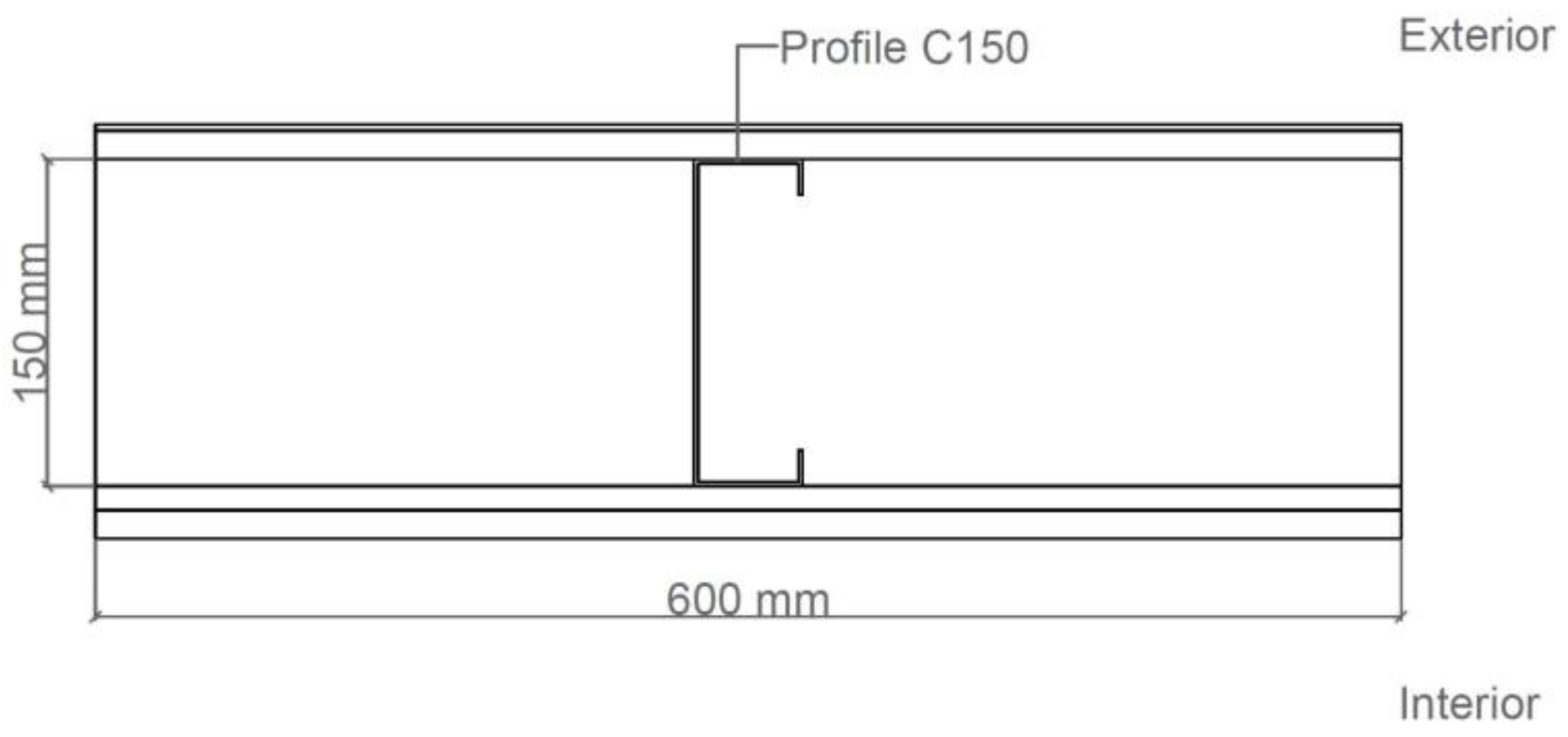
In order to calculate the U-value of the LSF facade walls, first it is necessary to identify a representative wall section to model. For a wall with a single layer of vertical steel studs and a frequency of 600 mm every two studs, standard ISO EN 10211 [
26] suggest taking advantage of its symmetry to position the adiabatic plans (zero heat flow). Therefore, a cross-section of the wall measuring 600 mm, with a steel stud in the core, was considered as a geometric model, as illustrated in
Figure 3.
4.2. Materials
In this study, three facade walls are considered, one for each LSF construction type. Each wall comprises a steel structure containing galvanized cold-formed steel studs with a “C” cross-sectional shape (150 mm × 43 mm × 15 mm × 2 mm).
Table 1 presents the thermal conductivity (λ) of each material assembled in the several walls.
4.3. Domain Discretization
The finite element mesh of a model in THERM [
27] is controlled by two parameters: by the “Quad Tree Mesh Parameter” and the “Maximum % Error Energy Norm”. While the first parameter relates to the maximum size of the initial subdivision, the second one sets a threshold for the error estimator during the iterative calculations. The model was calculated using an iterative method in which the default “Quad Tree Mesh Parameter” was set to its standard value of 6 and the “Maximum % Error Energy Norm” settled under 2%.
4.4. Boundary Conditions
The same boundary conditions, previously presented in
Section 3.1, were used across the whole paper in order to homogenize the results. In this sequence, the follow boundary conditions were set for external and internal environment: An external temperature equal to 0 °C and a convective surface heat transfer coefficient h
e = 25 W·m
−2·K
−1; the internal temperature was defined at 20 °C and h
i = 7.69 W·m
−2·K
−1. These convective surface heat transfer coefficients were established according to EN ISO 6946 [
15] for a horizontal heat flow.
4.5. Modelling Air Layers
The air layer inside the wall was modelled considering the equivalent thermal conductivity of a solid. EN ISO 6946 [
15] presents the equivalent thermal resistance values to use when modelling unventilated air layers. According to this standard, a thermal resistance (
RT) of 0.18 m
2·K·W
−1 is prescribed for air layers with thicknesses between 25 mm and 300 mm when the direction of the heat flow is horizontal. The solid-equivalent thermal conductivity of each air layer was calculated using the known equivalent thermal resistance (
R) and the air layer thickness (
d), according to Equation (1),
4.6. Accuracy Verification
The accuracy of the 2D FEM algorithm of the software used in the computations (THERM) was performed by comparison taking into account two standards, namely EN ISO 10211 [
26] and EN ISO 6946 [
15] and the 3D FEM software ABAQUS/CAE [
28].
4.6.1. Verification against EN ISO 10211
In addition to establishing the specifications to be followed when modelling thermal bridges, EN ISO 10211 [
26] also provide several test cases (two 2D test cases and two 3D test cases) in order to evaluate the precision of the numerical algorithms for computing heat flows and surface temperatures.
With the intend to evaluate the results’ accuracy and reliability obtained using FEM THERM [
27] algorithm, the authors modelled both 2D reference test cases prescribed in Annex A of EN ISO 10211 [
26]. To be classified as a 2D steady-state high precision method, the obtained results should be in accordance with those provided by the standard.
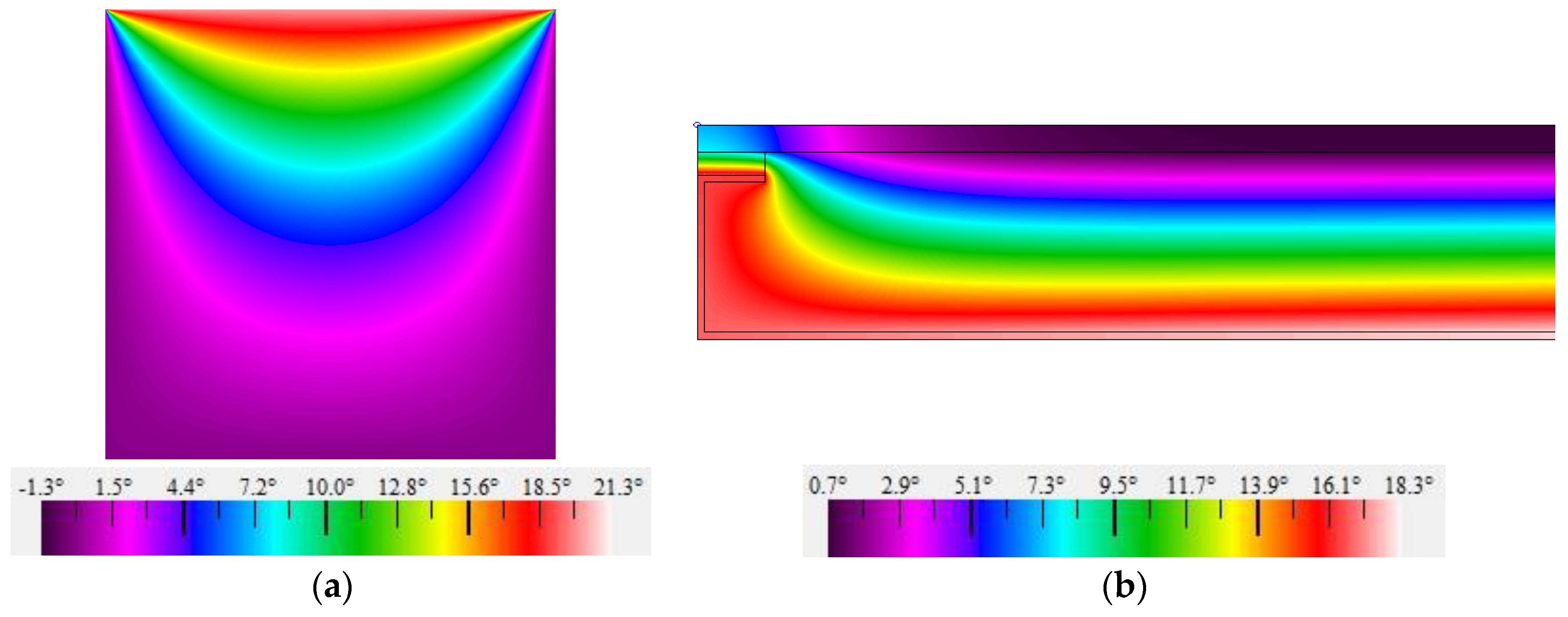
Figure 4 illustrates the temperature distribution obtained for both 2D test cases. In Case 1, ISO 10211 [
26] imposes that the difference between the temperatures obtained at several points, calculated by the method being validated, and the analogous temperatures presented in the standard should not exceed 0.1 °C. This tolerance was respected by all the obtained results. In Case 2, beyond the same temperature requirements of Case 1, EN ISO 10211 [
26] also requires that the heat flow calculated by the method being validated and the one given by the standard shall not exceed 0.1 W·m
−1. In this case, the obtained values do not show any difference from the analogous values presented by the standard. These results ensure not only the precision of THERM software algorithm [
27], but also the authors' skills to use it.
4.6.2. Verification against EN ISO 6946
To further evaluate the accuracy of the used FEM software THERM [
27], the thermal resistance of a wall with homogeneous materials was also calculated and compared with the predicted analytic value obtained according to EN ISO 6946 [
15] orientations.
Table 2 presents the thicknesses and thermal characteristics of the modelled material layers in this verification.
A convective surface heat transfer coefficient equal to 25 W·m
−2·K
−1 and 7.69 W·m
−2·K
−1 were respectively applied to the outer and inner surface, in accordance with EN ISO 6946 [
15]. With this data, a U-value equal to 0.2222 W·m
−2·K
−1 was computed using THERM [
27] software.
When submitted the same model under the EN ISO 6946 [
15] analytic calculation method, according to expressions (4) and (10), the same U-value (0.2222 W·m
−2·K
−1) was obtained. This second verification confirms the accuracy of this FEM software in performing thermal analysis.
4.6.3. Verification against ABAQUS/CAE Finite Element Software
In addition to the verification against the former two standards, a comparative study with 3D FEM software ABAQUS/CAE [
28] was performed. In this analysis, the U-value of the wall previously illustrated in
Figure 1b was computed using both ABAQUS/CAE and THERM software. Instead of 100 mm of EPS, as exposed in this figure, 25 mm of EPS was considered. The thermal proprieties of the modelled materials were shown in
Table 1. Regarding the boundary conditions, the adopted values in
Section 4.6.2 were replicated.
When computed with ABAQUS/CAE a U-value equal to 0.7660 W·m−2·K−1 was reached. Submitting the same model under THERM calculations, an analogous U-value equal to 0.7661 W·m−2·K−1 was provided. These results show a difference of just 0.0001 W·m−2·K−1, highlighting again the THERM software accuracy robustness, this time against a 3D FEM software.
5. Results and Discussion
In this section, the thermal insulation influence/effectiveness in reducing thermal bridges originated by the steel frame in LSF facade walls is evaluated. During this study, three facade walls are considered, one for each type of construction, as previously presented in
Section 3.1.
An overview of the totality of the studied models is displayed in
Table 3. As presented in this table, these three wall types only differ in the sort and position of the thermal insulation employed, with the remaining wall elements being kept constant. Eighteen models with thicknesses between 25 mm and 150 mm are under analysis. In the hybrid typology, for the sake of simplicity, it was chosen to distribute the insulation in equal proportion among the ETICS and the batt insulation.
Next, the eighteen obtained results are presented and discussed. To evaluate the effectiveness of the thermal insulation for mitigating the heat flow through the steel studs, two U-values are computed/presented. The first is the real U-value of the facade wall with the steel studs (Ureal), while the second neglects the steel frame by assuming homogeneous layers (Uhom).
Notice that although EN ISO 6946 [
15] indicates that final results of the thermal resistance values should be presented rounded to two decimal places, four decimal places are used in the presentation of the U-values, to improve the accuracy of the comparative analysis when similar values are obtained.
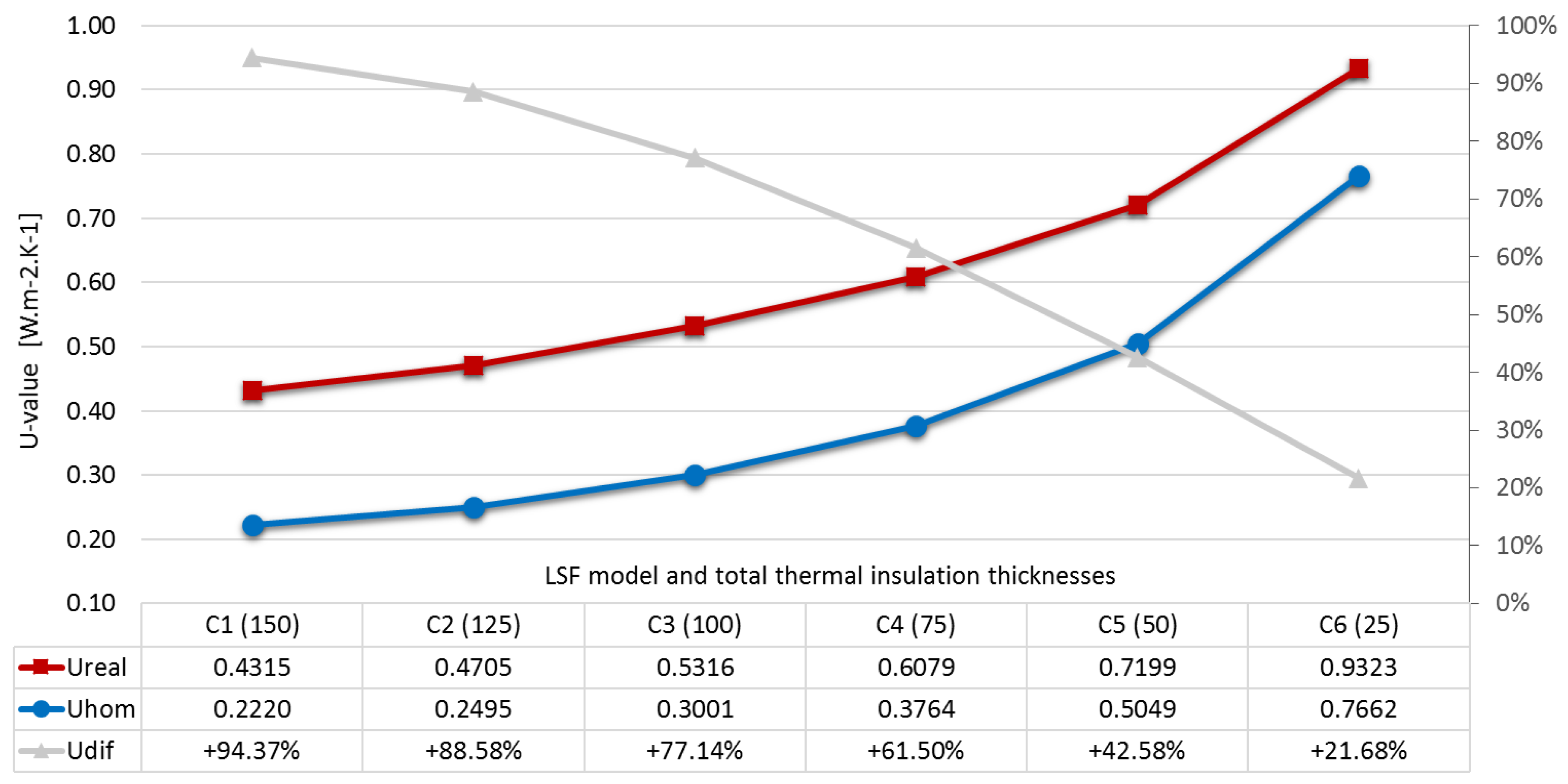
5.1. Cold Frame Construction
Figure 5 displays the U-values obtained for LSF cold frame construction with and without the steel studs. It can be observed how severely impaired thermal insulation efficiency can be due to the presence of the steel studs in the air cavity. Notice that in this type of construction the thermal insulation is penetrated through all its thickness by the steel studs. This feature originates low thermal resistance paths across it, increasing the U-value of the LSF wall. In these pathways, the heat energy flow is much larger when compared with the one in its vicinity.
Regarding this, the greater the insulation thickness in the air cavity is, and consequently pierced by the steel studs, the greater is the drop in the insulation effectiveness. Increases from 22% (Model C6) up to 94% (Model C1) of the U-value were reached when comparing the wall’s thermal performance with and without the steel studs.
It was also computed the U-value of the LSF wall without any thermal insulation (1.6383 W·m−2·K−1). This value is much larger (+0.7060 W·m−2·K−1) than the one obtained in Model C6 which means an improvement of 57% with only 25 mm of rock wool. Regardless of the insulation effectiveness being severely affected in cold construction facades, the improvement in the U-value with the introduction of a reduced insulation thickness, when compared with the total absence of insulation, is evident.
The obtained results show that in LSF constructions, applying thermal insulation in the air cavity leads to a poor effectiveness of this element, impairing the cost/benefit ratio. However, this positioning of the thermal insulation may be justified in some particular situations, such as the absence of space outside the air cavity (minimizing the total wall thickness) or to avoid sound insulation breaks due to resonances in the air cavity.
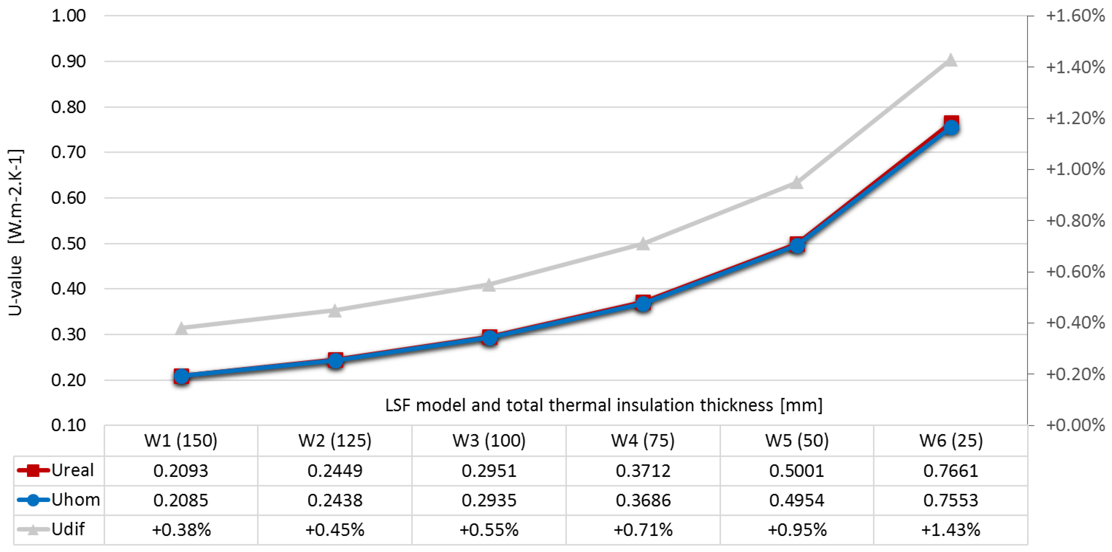
5.2. Warm Frame Construction
The thermal transmittance values for the LSF warm construction are presented in
Figure 6. In contrast with the previous typology, now the thermal insulation is not pierced by the structural steel studs, thus maximizing the facade walls’ thermal performance. Analysing
Figure 6, it can be verified the striking contrast between warm and cold constructions (
Figure 5) regarding the impact of the steel studs in the LSF facade walls’ thermal performance. Given the continuous thermal insulation of ETICS, the impact of the steel studs in the facade walls’ thermal behaviour is substantially reduced or even negligible (both curves in
Figure 6 almost overlapped). The increase in the U-value due to the presence of the steel studs ranges from only 0.4% (W1) to 1.4% (W6).
5.3. Hybrid Frame Construction
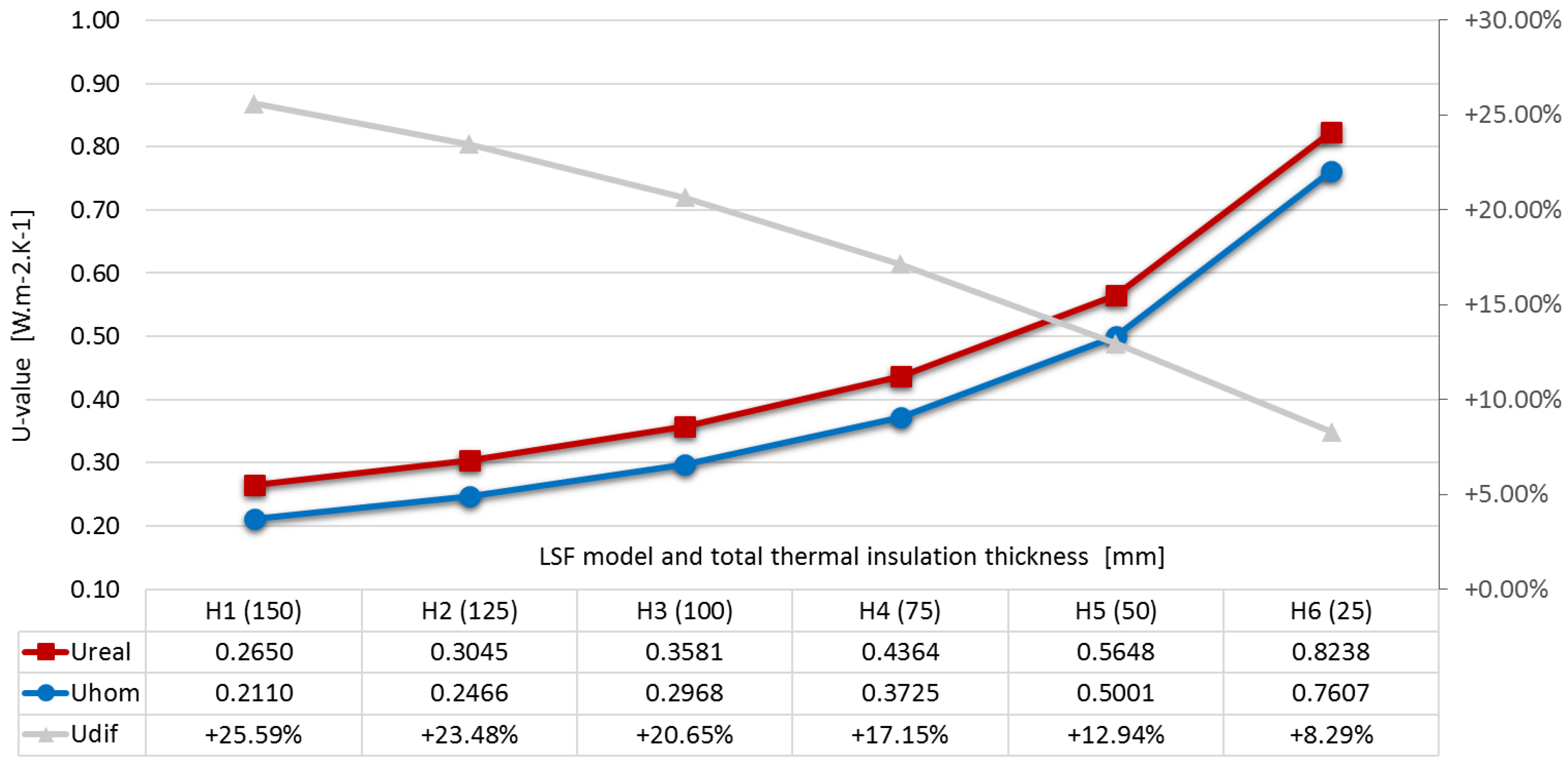
As hybrid solutions between the two previous ones, also the obtained results within this typology of construction are expected to reveal intermediate values to those obtained previously, as illustrated in
Figure 7.
As expected, by analogy with the LSF cold frame construction results (
Figure 5), the hybrid walls’ overall thermal performance is not enhanced due to the presence of the batt thermal insulation pierced by the steel studs, which significantly disrupt its efficiency. In this type of construction the main element responsible for improving facade walls thermal performance is the continuous outer layer of insulation. These results show once again the importance of the exterior insulation layer in LSF facade walls. When distributing the insulation among the air cavity and the exterior layer the first one must be reduced to the indispensable to avoid acoustic resonances breaks and reduce the wall thickness.
5.4. Results Overview
Table 4 presents an overview of the results obtained in this work for the types of LSF construction. In addition to the U
real and the U
hom values of the walls, the difference between both is also presented as a percentage.
From the analysis of
Table 4, it can be seen how different the U-value of the facade walls can be regarding the position of the insulation. These differences are caused by the unequal capability of the several analysed solutions in reducing the steel studs’ thermal bridge expression.
In the cold construction context, the discrepancy between the Uhom and Ureal is more pronounced when the thermal insulation thickness pierced by the steel studs increases. On the other hand, in warm construction, the increase of the continuous thermal insulation leads to the mitigation of the thermal bridges expression and consequently both U-values (Ureal and Uhom) becomes even more similar.
As a constructive solution that maximizes the efficiency of the entire applied thermal insulation, warm construction, for an insulation thickness of 150 mm, the U-value just increases 0.38% (ΔU) when considering the steel studs. On the other hand, considering the cold construction, this increase assumes a value of 94.37%. These differences give rise to a fluctuation of 0.2222 W·m−2·K−1 in the Ureal value, for the same thermal insulation thickness (150 mm).
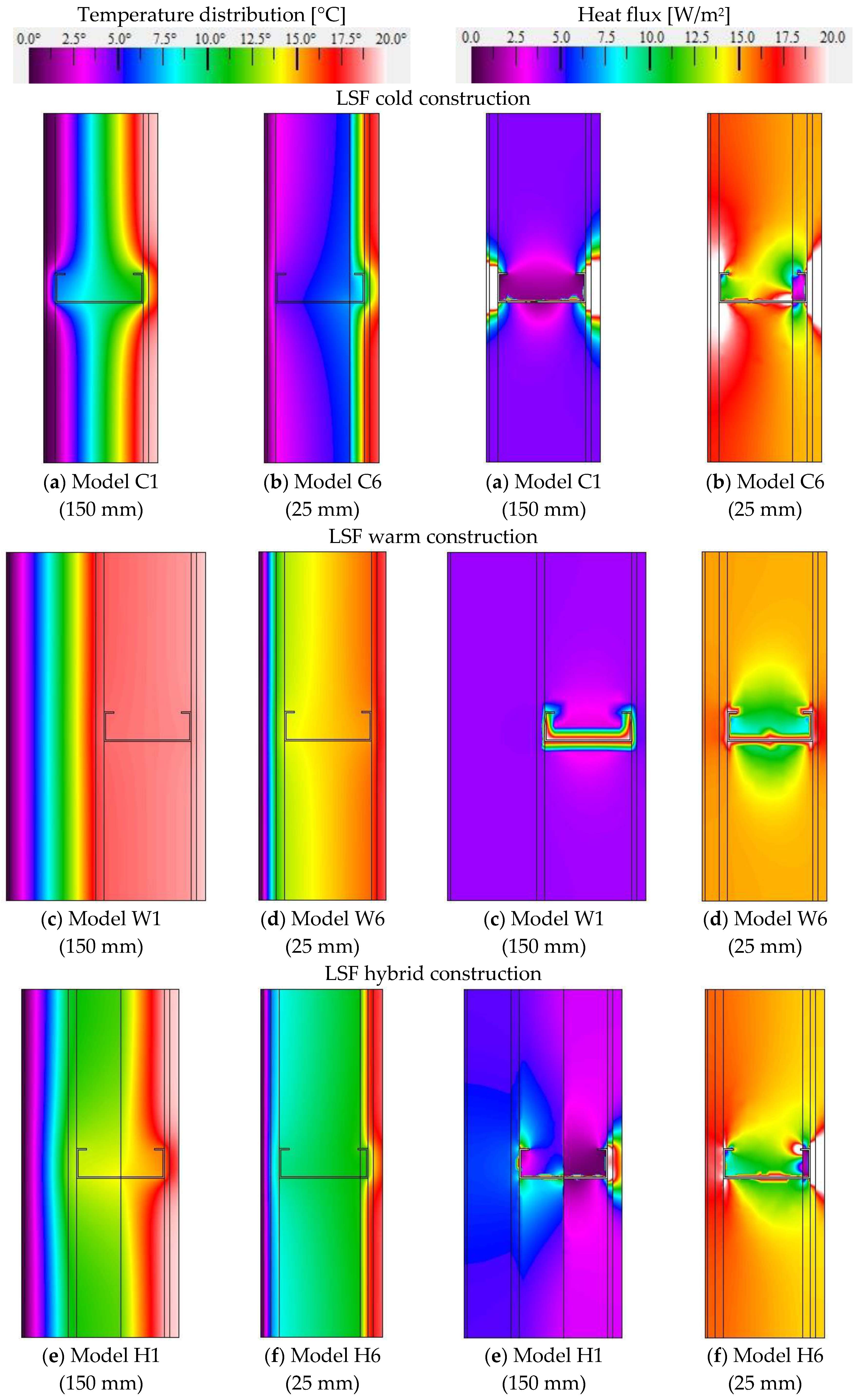
The previous considerations, related to the influence of the steel studs in the thermal insulation effectiveness in the different constructive types are supported by
Figure 8 which illustrates the flux magnitude and temperature distributions for the models with the lower and higher thickness of thermal insulation within each construction type, namely, with 25 mm and 150 mm of insulation.
It can be observed that in the cold constructive typology (
Figure 8a,b) that there is a continuous path of lower thermal resistance connecting the indoor and the outdoor environments without a significant thermal break provided by the insulation. When the thermal insulation is placed outside the steel frame, not being pierced by it, this element provides an effective thermal break, without an existing easy continuous path for heat flow to occur. This is evident in the warm construction type (
Figure 8c,d) in which, although the heat flow path to the exterior environment starts concentrated along the steel studs, the outer insulation layer ensures the overall solution thermal robustness.
When the thermal insulation is pierced along its thickness the heat flow is concentrated in the metal studs along its way. Considering the Model C1, it can be observed that the flow along the studs reaches values much higher than the adjacent zones of thermal insulation. This phenomenon supports the registered percentage difference between the Uhom and the Ureal as the pierced insulation thickness increases. On the other hand, increasing only the unpierced insulation, as in the warm type, similar decreases in the Ureal and Uhom values are registered and consequently the percentage difference is very reduced, or even insignificant.
In addition to thermal comfort, the hygrothermal performance must be analysed as well. Examining the temperature distributions present in
Figure 8, the range of values regarding the surface and interstitial temperatures that can occur in the different wall types can be observed. In warm construction, unlike the other two, there is a homogenization of the interior superficial temperatures, presenting non-critical values regarding the appearance of these pathologies in the interior sheathings, reinforcing the better performance of this solution when compared with the other construction types.
5.5. Thermal Regulation Requirements
In this section the obtained thermal transmittance values (
Ureal) are compared with the requirements provided by the Portuguese Thermal Regulation for Residential Buildings, REH [
5]. Due to the variation of climatic characteristics throughout Portugal, REH [
5] defines three winter climatic regions: I1, I2, and I3, the latter being the most severe, i.e., the coldest one. To each climatic zone corresponds different minimum thermal performance requirements for vertical elements in contact with the exterior environment (facade walls), translated by a maximum U-value. For new buildings this value is set at 0.50, 0.40, and 0.35 W·m
−2·K
−1, regarding zone I1, I2, and I3, respectively.
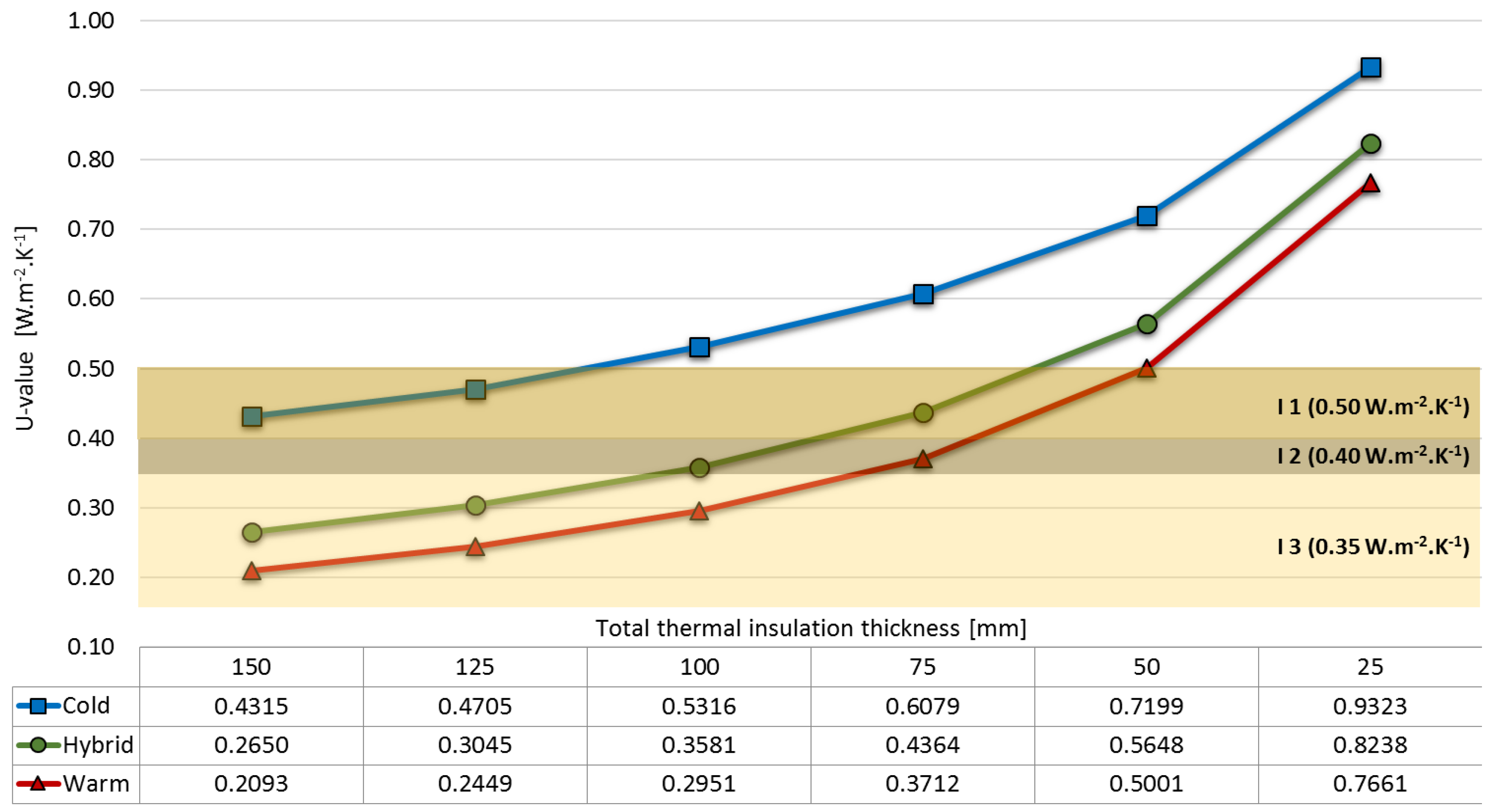
Figure 9 presents the obtained U-values regarding the various insulation thicknesses, within the three LSF construction typologies analysed: cold, hybrid, and warm, taking into account the steel studs (U
real). In the same figure is also highlighted the REH U-value levels, for the three climatic zones described above.
Starting the analysis by the cold construction, it is possible to verify how poor the facade walls’ thermal behaviour can be. For this type of construction, only the solutions with 150 mm and 125 mm of thermal insulation can verify the mandatory maximum U-value corresponding to climate zone I1, which is the mildest one. The remaining insulation solutions analysed for this type of construction are not applicable to new buildings built in Portugal.
In contrast to the previous type of construction, the warm construction has the potential to meet all of the mandatory requirements imposed to the three climatic zones. It is verified that with only 100 mm of thermal insulation the corresponding U-value is suitable for the most demanding climatic zone (I3) and 75 mm does not check this requirement by a small margin. Notice that using 100 mm of thermal insulation inside the air cavity, the analysed cold construction wall does not verify any of the requirements.
Figure 9 reveals that this level of default, in the warm construction, is only confirmed for a thermal insulation thickness inferior to 50 mm.
The results obtained in the scope of LSF hybrid construction analysis, once again, reveal intermediate results to those computed for the two other typologies. In this last constructive typology, although equal total insulation thicknesses were employed (outside and inside the air cavity), the results presented in
Figure 9 show that the obtained U-values are closer to the ones obtained for LSF warm construction. In this type of construction, although the effectiveness of thermal insulation in the air cavity being very impaired, the outer insulation layer ensures that the facade walls’ overall thermal performance is not as compromised as it is in the case of cold frame constructions.
5.6. Point Thermal Bridges Relevance
Beyond linear thermal bridges caused by the steel studs along its length, another type of thermal bridges can be identified in LSF facade walls current zones, point thermal bridges, usually driven by mechanical fixations (e.g., fixation of the EPS to the OSB exterior sheeting or in the fastening of the steel studs to both OSB sheathings).
Currently, the fixation of the EPS to the OSB exterior sheeting is accomplished with plastic fixings and may be ignored in the overall U-value calculations, as indicated by Doran and Gorgolewski [
29] and prescribed by standard EN ISO 6946 [
15] whenever the thermal conductivity of the fastener is less than 1 W·m
−1·K
−1. In the second example, metallic self-drilling screws are usually used.
To demonstrate the relevance of the self-drilling screws in facade walls U-value and to justify why has this effect been neglected in the modeled situations, H1 model was re-evaluated considering these fixation elements (not illustrated). It was chosen H1 model for this analysis because it represents the most frequent type of LSF construction, hybrid construction.
Considering the steel screws in the facade wall thermal behaviour analysis it was computed a U-value of 0.2699 W·m−2·K−1. Bearing in mind that it was obtained a U-value of 0.2650 W·m−2·K−1 for the same model without the screws the resulting U-value difference is only 0.0049 W·m−2·K−1. Consequently, it was concluded that the point thermal bridges driven by these fixations could be neglected in the present analysis.
6. Conclusions
In this paper a numerical study was developed to assess the thermal insulation influence/effectiveness regarding its position in LSF facade walls. This issue is particularly relevant in LSF structures given the high thermal conductivity of the structural steel frame. Furthermore, the influence of point thermal bridges driven by the mechanical steel fixations was also briefly analysed for one hybrid frame construction model. It was concluded that these point thermal bridges could be neglected in the analysis, given the very small difference in the obtained U-value of the facade wall (only 0.0049 W·m−2·K−1).
The obtained results show a very large fluctuation in the effectiveness of the insulation due to its positioning on the LSF facade walls, with a direct consequence on their overall thermal performance (U-value). For the same thermal insulation thickness, differing exclusively in its position in the wall, differences between Uhom and Ureal reached values as distinct as 0.38% and 94.37%.
When the insulation is placed between the steel frame (batt insulation), pierced along its length by the steel studs, the greatest drops in the effectiveness of this component occurs. Therefore, the overall thermal performance of LSF facade walls’ built under hybrid constructive type and especially cold typology can be seriously impaired. It was shown that, in cold construction facade walls, considering the effect of the steel stud piercing the insulation layer leads to a U-value increase from 21.68% to 94.37%.
Moreover, applying thermal insulation only outside the steel frame, corresponding to the warm construction type, maximizes its performance, leading to the reduction of steel studs influence to insignificant values. In this type of construction the maximum computed difference between Uhom and Ureal was less than 1.5%. It was concluded that is imperative to apply an unpierced continuous thermal insulation layer, acting as a heat flow thermal break across LSF facade walls. The effectiveness of this thermal break strategy increases as the insulation thickness increases.
Moreover, it was shown that when the thermal insulation effectiveness is not reduced due to the steel frame negative influence, as it happens in warm LSF construction, the analysed walls show the capability to meet the thermal regulation requirements (e.g., REH) with lower insulation thicknesses and consequently minimized monetary costs and environmental impacts. On the other hand, facade walls built according to the cold construction type can require high amounts of thermal insulation in order to reach the most demanding requirements imposed by the same thermal regulations and consequently increasing its costs and the total thickness of facade walls.
Therefore, to achieve a high level of sustainability and energy efficiency is essential to promote an adequate design of this type of buildings. These objectives are essentially achieved through an efficient choice of the constructive solutions, enabling the achievement of objectives that lead to energy optimization of LSF structures. It was shown that the position of thermal insulation in LSF facade walls plays a major role in its thermal performance effectiveness. Consequently, a wide range of thermal performances can be obtained regarding exclusively this issue. In order to increase operational energy efficiency and minimize embodied energy, reducing also environmental impacts of LSF constructions is essential to consider this aspect as primordial.
In order to validate the above results against experimental data, the authors intended to perform an experimental campaign using a guarded hot box. Considering similar comparisons between numerical and experimental resulted previously obtained by one of the authors, regarding LSF walls thermal performance, very similar results are expected.


