Article

Computational Combination of the Optical Properties of Fenestration Layers at High Directional Resolution

by
Lars Oliver Grobe
Competence Center Envelopes and Solar Energy, Lucerne University of Applied Sciences and Arts, 6048 Horw, Switzerland
Buildings 2017, 7(1), 22; https://doi.org/10.3390/buildings7010022
Submission received: 19 November 2016 / Accepted: 7 March 2017 / Published: 10 March 2017

Abstract

:
Complex fenestration systems typically comprise co-planar, clear and scattering layers. As there are many ways to combine layers in fenestration systems, a common approach in building simulation is to store optical properties separate for each layer. System properties are then computed employing a fast matrix formalism, often based on a directional basis devised by JHKlems comprising 145 incident and 145 outgoing directions. While this low directional resolution is found sufficient to predict illuminance and solar gains, it is too coarse to replicate the effects of directionality in the generation of imagery. For increased accuracy, a modification of the matrix formalism is proposed. The tensor-tree format of Radiance, employing an algorithm subdividing the hemisphere at variable resolutions, replaces the directional basis. The utilization of the tensor-tree with interfaces to simulation software allows sharing and re-use of data. The light scattering properties of two exemplary fenestration systems as computed employing the matrix formalism at variable resolution show good accordance with the results of ray-tracing. Computation times are reduced to 0.4% to 2.5% compared to ray-tracing through co-planar layers. Imagery computed employing the method illustrates the effect of directional resolution. The method is supposed to foster research in the field of daylighting, as well as applications in planning and design.

1. Introduction

Complex Fenestration Systems (CFSs) improve visual and thermal comfort by controlling the admission and distribution of daylight. They have a two-fold, beneficial effect on electrical energy demand. Operation of artificial lighting can be minimized due to the increased supply of daylight and the reduced need to operate sun-shades. Demand for cooling decreases due to lower internal gains by lighting and the control of solar gains [1,2,3]. Typical CFSs comprise a set of co-planar, clear and scattering layers. These layers are chosen from a range of coated and uncoated glazing, interior or exterior sun-shades and devices for glare control, such as Venetian blinds or woven roller shades. The optical properties of a CFS result from the particular combination of its layers and includes the complex inter-reflection within the system [4].
Daylight and building energy simulation are applied to predict the impact of CFSs on comfort conditions and energy demand [5,6]. For assessments of thermal comfort, models must accurately predict solar heat gain depending on the incident direction of solar irradiation [7]. Visual comfort assessments rely on models that replicate not only the total flux, but the distribution of light into the building interior, adding the outgoing direction as a second independent variable. Models fulfilling the requirements of thermal and visual comfort assessment are established for fenestration systems comprising clear layers, such as double or triple glazing, and implemented in simulation software. CFSs comprising scattering or re-directing layers impose a particular challenge due to their almost infinite variety and the characteristic irregularity of their optical properties [8].

1.1. Modeling Complex Fenestration Systems with Bidirectional Scattering Distribution Functions

The effect of CFSs on incident light can be expressed by their Bidirectional Scattering Distribution Functions (BSDFs). The BSDF describes light transport through a thin surface element, such as thin CFSs and their layers, for any pair of incident and scattered outgoing directions ( θ i , ϕ i ; θ s , ϕ s ) [9,10]. The implicit definition of the BSDF is given by the rendering equation [11]:
L s ( θ s , ϕ s ) = θ i , ϕ i ω i = 4 π B S D F ( θ i , ϕ i ; θ s , ϕ s ) · L i ( θ i , ϕ i ) · c o s ( θ i ) · d ω i ,
where L s ( θ s , ϕ s ) is the scattered outgoing, L i ( θ i , ϕ i ) the incident radiance and ω i the solid angle of the light source seen from the surface. Equation (1) shows this simplest formulation of the BSDF depending only on incident and outgoing directions. Further variables may be introduced to resolve spatial non-uniformity or the dependence on wavelength [12].
Analytical models for the BSDF of CFSs have been proposed, but share the limitation that they are applicable only to particular classes of systems [13,14]. The application of a directional basis, merging ranges of both incident and outgoing directions into patches, allows one to replace the BSDF as a continuous function by a discrete set of luminous coefficients [15]. For each combination of one patch on the incident, and one on the outgoing hemisphere, this coefficient holds the average BSDF of all incident and outgoing directions contained by the patch. This average evaluates the bi-conical transmission, an optical property that can be directly measured using gonio-photometers [16,17] or computed employing analytical models or Monte Carlo ray-tracing techniques [18,19,20].

1.2. Computational Combination of Bidirectional Scattering Distribution Functions

To leverage the fact that an almost infinite number of CFSs is formed by combining a limited set of available layers, measurements and the creation of libraries, such as the CGDB [21], typically aim to characterize individual layers rather than entire system assemblies. Computational methods to combine the BSDF of one fenestration layer or a subsystem (BSDF L ) with that of adjacent layers into the effective BSDF of an entire fenestration system (BSDF S ) are then applied to provide models for simulation. A matrix formalism is employed in analogy to the computation of scattering on stacks of clear layers [22]. Forward and backward reflection and transmission R f f , T f b , T b f , R b b form the four components of the BSDF (Table 1) and are each represented as a matrix of m incident and n outgoing directions [23,24].
In building sciences, the matrix formalism was proposed to evaluate the absorption of light on individual layers as part of the computation of solar heat gain through CFSs [25,26]. The luminous coefficients c m , n for the four component matrices are ordered such that the columns m correspond to 145 incident and rows n to 145 outgoing directions:
M = o u t i n ( c ( θ i , 1 , ϕ i , 1 , θ s , 1 , ϕ s , 1 ) c ( θ i , 145 , ϕ i , 145 , θ s , 1 , ϕ s , 1 ) c ( θ i , 1 , ϕ i , 1 , θ s , 145 , ϕ s , 145 ) c ( θ i , 145 , ϕ i , 145 , θ s , 145 , ϕ s , 145 ) )
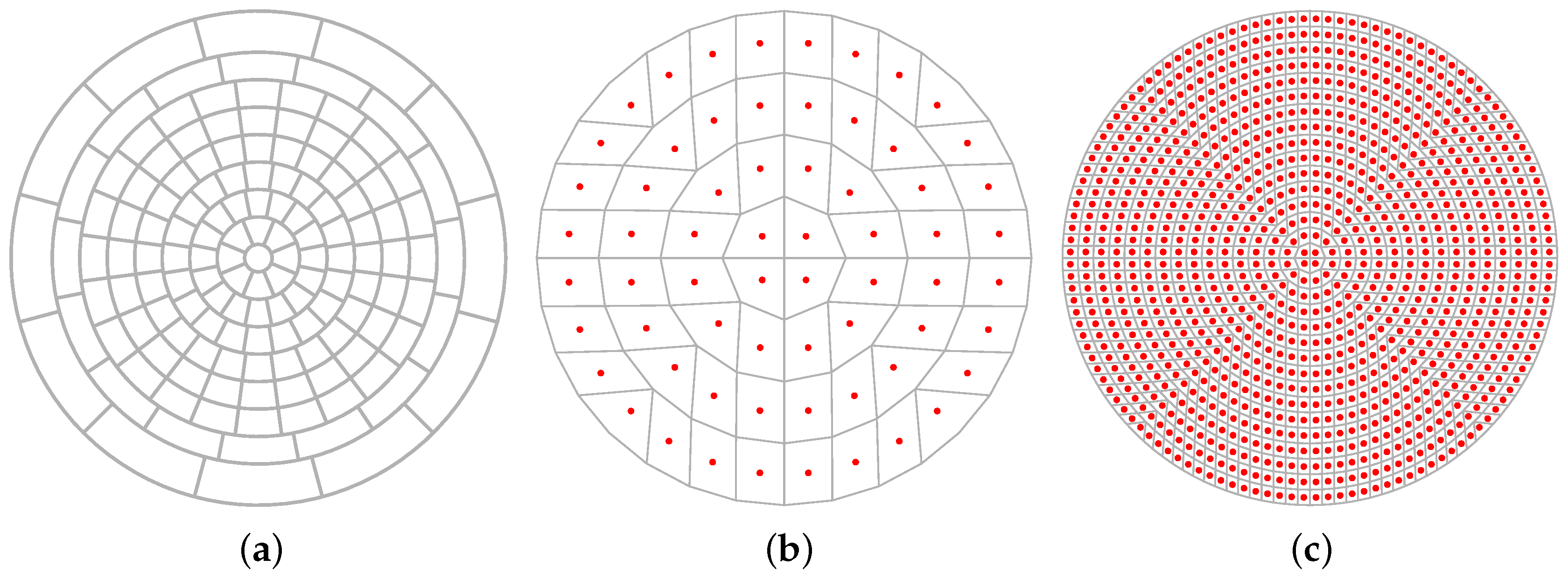
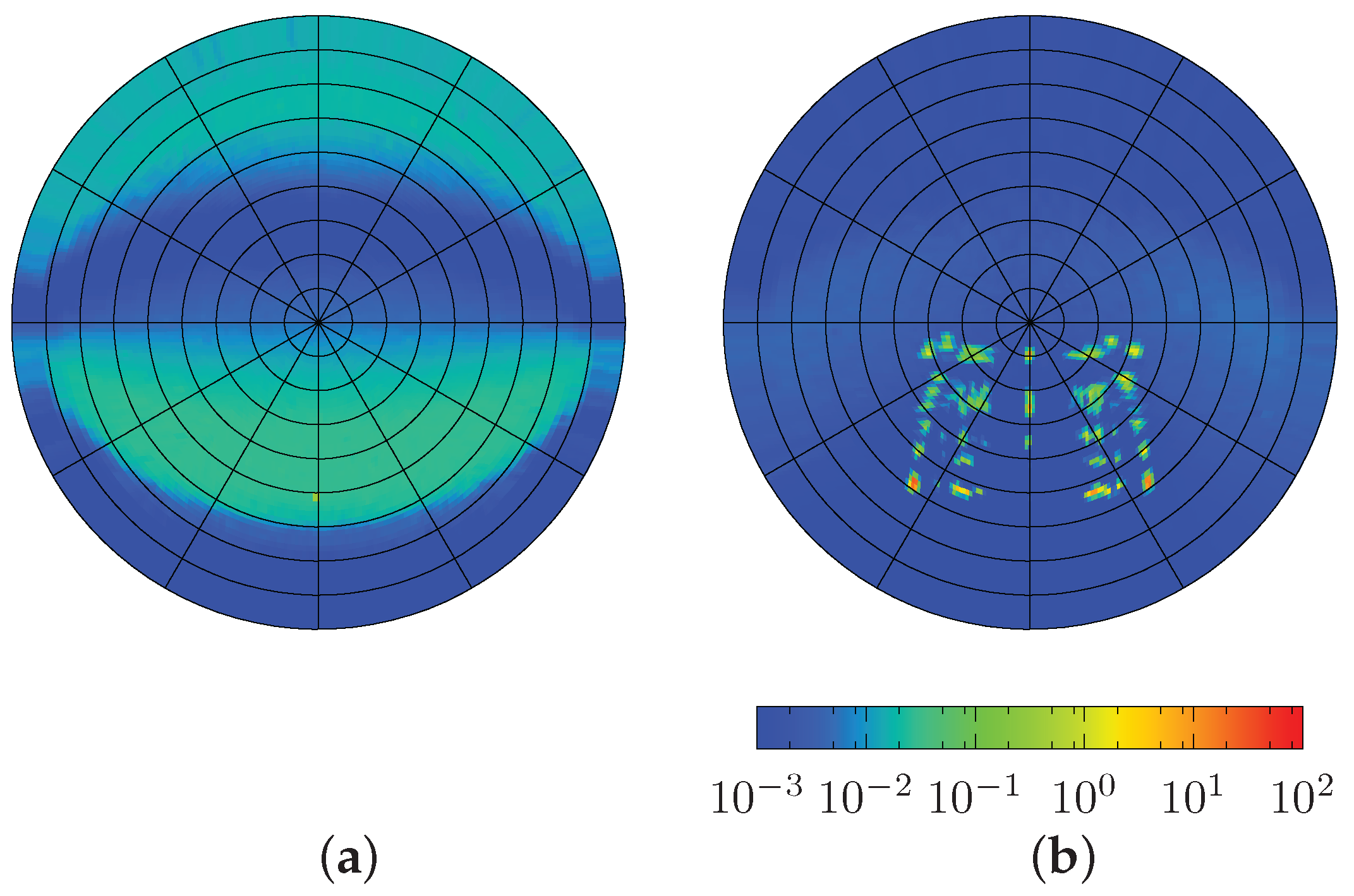
The directional basis of 145 defined directions will be referred to as the Klems basis after its inventor and is illustrated in Figure 1a. By convention, the forward direction corresponds to incident light from the building exterior. Purely specular transmission and reflection, defined by equal incident and outgoing direction, form a special case that can be described by diagonal matrices.
The coupling of the outgoing directions of one layer to the corresponding incident directions on the next adjacent layer is implemented by a diagonal propagation matrix Λ. Its coefficients are set to the projected solid angle of the patch represented by each coefficient c m = ω m · cos θ m . The BSDF S of the entire system, including inter-reflection between layers, is then computed by iteratively repeating the combination of BSDF L s for pairs of layers or sub-systems L 1 and L 2 :
T f b , S = T f b , L 2 · ( I Λ · R b b , L 1 · Λ · R f f , L 2 ) 1 · Λ · T f b , L 1 R f f , S = R f f , L 1 + T b f , L 1 · ( I Λ · R f f , L 2 · Λ · R b b , L 1 ) 1 · Λ · R f f , L 2 · Λ · T f b , L 1 T b f , S = T b f , L 1 · ( I Λ · R f f , L 2 · Λ · R b b , L 1 ) 1 · Λ · T b f , L 2 R b b , S = R b b , L 2 + T f b , L 2 · ( I Λ · R b b , L 1 · Λ · R f f , L 2 ) 1 · Λ · R b b , L 1 · Λ · T b f , L 2
To overcome the effects of spectral averaging, the method can be applied to spectral channels and is as such implemented in Window [27]. With its interfaces to various building energy simulation tools and the CGDB, this software is currently the de-facto standard for modeling of multi-layer CFSs.

1.3. Data-Driven Models of the Bidirectional Scattering Distribution Function in Daylight Simulation

Due to its general applicability, discrete representations of the BSDF have been employed in lighting simulation to model the irregular transmission through CFSs.
Distributed as part of the daylight simulation software Radiance, mkillum evaluates BSDF data during the pre-computation of light transport through fenestration. It replaces the CFS by a virtual light-source in the diffuse-indirect inter-reflection calculation [15]. The Klems basis comprising 145 patches is applied to both incident and outgoing directions. A modification of mkillum substitutes the Klems basis by 145 incident and 1297 outgoing directions, following a recommendation by the International Energy Agency (IEA) [28,29,30]. Current versions of Radiance support the use of data-driven models, not only in the pre-computation of virtual light sources. A data-driven reflection and transmission model allows one to describe any CFS only by a surface and its BSDF S in all phases of the simulation. The support of the Klems basis provides an interface to the CGDB as a data provider, as well as to Window to model glazing assemblies from chosen BSDF L s. The data-driven model is in wide use especially in Climate-Based Daylight Modeling (CBDM) workflows, such as the Three-Phase Method (TPM). Shared among software tools, such as Window, EnergyPlus and Radiance, the Klems basis backs a consistent modeling approach in multi-domain simulation [31,32].
The directional resolution of the Klems basis has been found to be sufficient in simulations aiming for illuminance-based performance metrics. However, its adequacy in the computation of imagery such as applied in the prediction of glare and visual comfort has been questioned [33]. Radiance addresses this limitation by a refined representation of the BSDF. Rather than applying a fixed directional basis, patches are defined by mapping regions of a sub-divided square to the hemisphere. A symmetric subdivision of both axes of the square by the base of two results in 2 k · 2 k patches, with typical k = 3 to 7. An algorithm maps the boundaries of the sub-squares to directions θ , ϕ and leads to a set of patches of equal projected solid angle and configurable resolution 2 2 · k = 64 to 16384. The resulting patches are shown for two exemplary resolutions ( k = 3 and k = 5 ) in Figure 1b,c. A four-dimensional tensor (dimensions relating to θ i , ϕ i , θ s , ϕ s ) can consequently hold the 2 4 · k luminous coefficients for 2 2 · k incident and 2 2 · k outgoing directions of one BSDF component [34]. An optional data-reduction pass processes the tensor into a hierarchical, four-dimensional tree structure by adapting its resolution according to the local variance of the initial set of coefficients. The adaptive resolution preserves important detail, but drastically reduces the size of the model. An interface to load, cache and query the model is provided with libBSDF as part of the open source software Radiance. This approach to store the BSDF at configurable resolution will be referred to as the Shirley–Chiu algorithm, after the inventors of the underlying disk-to-square mapping algorithm [35].
While both the generation of BSDFs and its application in daylight simulation at high resolution are supported in Radiance, the combination of BSDF L s of adaptive resolution in analogy to the matrix formalism implemented in Window is not possible. Modeling of CFSs by the data-driven model applied to co-planar surfaces is not feasible due to the computational expense of ray-tracing. Horizontal research designs aiming to cover many different combinations of fenestration layers, as well as planners evaluating alternatives, are therefore currently limited to models of low resolution.

2. Objectives

An extension of the matrix formalism is proposed to support the combination of BSDF L s at variable resolution. Three criteria shall be fulfilled to match the requirements of daylight simulations:
  • BSDF L s of different directional resolution shall be combined. This reflects the fact that descriptions of layers with very different optical characteristics, often leading to different approaches in their characterization by measurement or simulation, have to be combined.
  • The directional resolution of the resulting BSDF S shall be configurable. The target resolution of the system’s BSDF S depends on factors such as the characteristics of the CFS, as well as the later application of the model in assessments requiring different degrees of accuracy.
  • Support for the data-driven reflection and transmission model in Radiance shall ensure the applicability of the method in visual comfort assessments and leverage the data-reduction algorithm implemented in Radiance. The compact representation allows one to make use of libraries of BSDF L data in analogy to the CGDB and is crucial to employ data-driven models in simulations with often complex and detailed architectural models.
The method shall be tested by applying it to two exemplary CFSs and comparing its results to Monte Carlo ray-tracing through geometric models. To illustrate the impact on computation time, the method is compared to ray-tracing through co-planar BSDF L s.

3. Method

The Shirley–Chiu algorithm is proposed to replace the Klems basis in the matrix formalism to combine BSDF L s. This extended matrix formalism employs the Radiance locally adaptive tensor-tree format to reduce the size of BSDF L s as input and BSDF S s as output. The implementation in C++ uses the Eigen library [36] for matrix computations and functions from Radiance to read, sample and write BSDF data. Exemplary CFSs are selected to test the method by comparing its results to those of ray-tracing through geometric models and stacks of BSDF L s. Down-sampling of BSDFs from high to lower resolution supports the combination of datasets with different resolution and is employed to test the impact of resolution on direct-hemispherical optical properties.

3.1. Matrix Formalism Employing a Subdivision Algorithm of Variable Resolution

The Klems basis as originally proposed with the matrix formalism divides the hemisphere into patches of approximately equal solid angle. These patches, 1 to 145, allow one to address a region containing any incident direction by its index m. Likewise, the outgoing direction is assigned to the index of its corresponding patch n. Ordering bi-conical transmission and reflection as coefficients by m , n allows one to store each component of the BSDF in a matrix and to apply Equation (3).
The hardly parameterizable Klems basis is replaced by the Shirley–Chiu algorithm to relate i · j patches forming one hemisphere to cells of a square matrix H of i rows and j columns. Subsequently, the cells of the matrix H are re-ordered row-wise into one vector h of i · j elements so that any patch on the hemisphere can be addressed by its vector-index in analogy to the Klems basis. Unlike the Klems basis, this vector is of configurable length depending on the chosen directional resolution.
Applying this method both to incident and outgoing directions, any incident direction θ i , ϕ i is related to its corresponding index m and any outgoing direction θ s , ϕ s to index n. Similar to the component matrix based on the Klems basis, the indices m and n, representing incident and outgoing direction, become the position of the luminous coefficients in the component matrix M . This allows one to relate any coefficient c m , n with indices m , n = 1 to 2 2 k , 1 to 2 2 k in a component square matrix M of size m · n to a corresponding pair of incident and outgoing directions θ i , ϕ i , θ s , ϕ s :
M = o u t i n ( c ( θ i , 1 , ϕ i , 1 , θ s , 1 , ϕ s , 1 ) c ( θ i , 2 2 k , ϕ i , 2 2 k , θ s , 1 , ϕ s , 1 ) c ( θ i , 1 , ϕ i , 1 , θ s , 2 2 k , ϕ s , 2 2 k ) c ( θ i , 2 2 k , ϕ i , 2 2 k , θ s , 2 2 k , ϕ s , 2 2 k ) )
The parameter k defines the directional resolution of the BSDF. Given that i = j = 2 k and k m a x = 7 , the method is applicable at directional resolutions of < 2 or up to 2 2 · k m a x = 16,384 incident and outgoing directions. The resulting maximum size of the matrix is 2 4 · k m a x = 268,435,456 cells, corresponding to 1 GB per component assuming single precision floating point values.
The Shirley–Chiu algorithm ensures that the mapping of patches to matrix cells is cosine-weighted. The projected solid angle Ω of all patches is equal and propagation matrix Λ, relating outgoing and incident directions of adjacent layers, becomes a diagonal matrix with coefficients of equal value:
Λ = o u t i n ( Ω 1 Ω 2 2 k ) with all Ω = π 2 2 k

3.2. Pair-Wise Combination of Bidirectional Scattering Distribution Functions at Variable Resolution

The computation of the BSDF S of a CFS is implemented by a sequence of pair-wise combinations of layer BSDF L s. The combinations are repeated to sequentially add BSDF L s until all layers of the fenestration system have been merged into one data-driven model.
The tensor-tree representations of two layers are loaded calling functions of the libBSDF library as distributed with Radiance. As the convention in Radiance, being a backward ray-tracer, differs from that of the original matrix formalism in that it considers the interior to be the front surface, front and back components have to be flipped. For each layer, component matrices R f f , T f b , T b f , R b b of a size determined by the chosen target resolution are filled by sampling the tensor-tree for all pairs of incident and outgoing directions. The propagation matrix Λ is initialized (see Equation (5)) according to chosen resolution k. The components of the BSDF S are calculated according to Equation (3). The resulting components are again flipped to match the different conventions of front and back side in Radiance. They are then sequentially passed to the command rttree_reduce, generating a compact tensor-tree of each component, and merged into one file by wrapBSDF, adding the meta-data required to interpret the file by libBSDF. Both rttree_reduce and wrapBSDF are distributed with Radiance and could be employed to integrate the method into the daylight simulation software.

3.3. Combination of Bidirectional Scattering Distribution Functions of Different Resolutions

The parameterizable directional basis allows one to store BSDFs at different resolutions. However, the computational combination of BSDF L s according to Equation (3) is only defined for matrices of identical size. A sampling strategy must be therefore chosen to combine BSDF L s of different resolution and generate a BSDF S of given target resolution. The size of all matrices employed in the calculation is set according to the target resolution. The BSDF L of each layer is down- or up-sampled accordingly when the matrices are created. For cases where the target resolution of BSDF S is higher than the resolution of the input layer BSDF L , clusters of neighboring coefficients will share an identical value. If the resolution of BSDF S is smaller than that of BSDF L , proper sampling must ensure that, e.g., sharp peaks in the input BSDF L are not missed. In the current implementation, all coefficients of the high resolution dataset contained in one patch of the target dataset are sampled and averaged. Figure 2 shows the sampled directions, which equal the center points of the high resolution dataset and the low resolution patches of an exemplary target resolution. Adaptive oversampling of the BSDF L would reduce computational expense, but add complexity to the implementation.

3.4. Testing the Method and Its Impact on the Predicted Performance of Multilayer Fenestration Systems

3.4.1. Cases and Computational Generation of Bidirectional Scattering Distribution Functions

To test the validity and impact of the method, it is applied to two exemplary CFSs:
CFS1 
Flat specular blinds embedded in a double glazing unit comprise a simple case of a CFS with predictable scattering properties.
CFS2 
Tilted light-shafts embedded in a triple glazing unit redirect light admitted from a range of given incident directions. The array of light shafts is highly directionally selective, aiming at a complete exclusion of direct sunlight in overhead applications.
Three sets of simulation models are prepared. These provide (1) BSDF S s as input to the proposed method, (2) geometric models of the CFSs as input for ray-tracing as reference method to generate BSDF S s and (3) the input to combine BSDF L s by ray-tracing as an alternative method.
First, simulation models of the scattering layers of both CFSs are prepared for the generation of BSDF L s with genBSDF. Following the modeling convention in Radiance, the inside surface points upward. The clear glass panes are modeled by the Radiance built-in glass material. The scattering layers are geometrically modeled, and their BSDF L s computed by genBSDF. Parameters for genBSDF used in the generation of the layers’ BSDF L s are listed in Table 2. The generated tensor has four dimensions (−t4) corresponding to a mapping of θ i , ϕ i , θ i , ϕ i at resolution k = 7 . From each incident direction, −c n sample rays are sent. The chosen 163,840 rays ensure that an average of 163840 / 2 2 · 7 = 10 rays for each pair of incident and outgoing directions are averaged over the model area to sample its non-uniform characteristics. The resulting BSDF L s provide the input for our method.
A second set of geometric models is prepared for the entire assemblies CFS1 and CFS2. The composition of the models is illustrated in Figure 3. The BSDF S s for both CFSs are computed by genBSDF with identical parameters as given in Table 2. The resulting BSDF S s are used as a reference to test the validity of the extended matrix formalism.
Finally, the CFSs are modeled as stacks of surfaces. Each surface with its associated BSDF L represents one layer. The BSDF S s are computed using genBSDF. Ray-tracing through such stacks of BSDF L s is a challenge for the sampling algorithm, and parameters are relaxed to achieve results in acceptable times as shown in Table 3. With the BSDF L s being uniform over the layer surfaces, sampling parameter −c n is decreased. An additional parameter −ad n is set to reduce the number of rays spawned at each ray intersection of the diffuse-indirect calculation. The resulting BSDF S should agree with the results of the proposed method, but significantly prolonged computation times are expected. This alternative approach shall illustrate the higher performance of the matrix formalism.

3.4.2. Comparison of the Results of the Extended Matrix Formalism and Ray-Tracing

To test the validity of the extended matrix formalism employing the Shirley–Chiu algorithm, its results are compared with ray-tracing through the geometrical models. For one exemplary incident direction, the resulting BSDF S s of both CFSs are plotted in a cylindrical mapping of all outgoing scattered directions of the transmission hemisphere. The plotted distributions are qualitatively compared to test the capability of the method to replicate the characteristic features in the BSDFs. For this evaluation of the method’s validity, the ray-traced BSDF S s are considered to be the ground-truth, as the well-known ray-tracing algorithm in the computation of the BSDF S s is identical to the computation of the individual layers BSDF L s.
The cosine term c o s ( θ i ) in Equation (1) leads to an exaggeration of deviations in the BSDF at directions close to the grazing angle θ i = 90 . The BSDF is therefore converted into its equivalent Differential Scattering Function (DSF) prior to quantitative comparisons according to Equation (6).
D S F ( θ i , ϕ i ; θ s , ϕ s ) = B S D F ( θ i , ϕ i ; θ s , ϕ s ) · c o s ( θ i )
Global Accordance (GA) and Local Accordance (LA) are applied to compare the two DSFs of a CFS for one given incident direction [37]. These metrics are based on the pair-wise comparison of values for identical directions. If a sharp peak is accurately predicted for a direction minimally offset from the peak direction in the reference, this good accordance would not be accounted for because of the mismatch of peak directions. To reduce the sensitivity of the comparison to such slight directional mismatches, the resolution of both distributions is reduced (from k = 7 to k = 5 ) before the application of the metrics. This step merges 16 adjacent directions and thereby avoids artifacts due to sharp peaks and high frequency noise.
As defined in Equation (7), GA integrates the accordance f A , B of DSF A with reference B for all outgoing direction indices j into one metric. For applications in the comparison of gonio-photometric measurements of luminaires assuming identical instrumentation, a range of 98% to 99% is considered good and 99% to 100% very good [38]. When different instruments or computational methods are employed, a lower degree of accordance can be expected.
f A , B = 100 1 j = 1 n DSF A , j DSF B , j 2 j = 1 n DSF A , j + DSF B , j 2
LA as a directionally-resolved metric is employed to localize deviations in the DSFs. For a distribution A and a given reference B, LA is defined for any directional index j by Equation (8).
f j , A , B = 100 1 DSF A , j DSF B , j DSF A , j + DSF B , j

3.4.3. Comparing the Performance of the Matrix Formalism to Ray-Tracing

The computation times of the extended matrix formalism and the application of genBSDF to combine BSDF L are compared. Computation times are measured employing the time command, which is available on Unix-like operating systems [39]. The user time is reported, accumulating the times spent by parallel processes to give an absolute measure of computational cost. To minimize the influence of input-output operations in the sampling routine of genBSDF, the model including its data-driven BSDFs was stored on a Random-Access Memory (RAM) disk. In typical applications, access to the files containing the data-driven models would add up on the computation time for both techniques.

3.4.4. Testing the Down-Sampling of Bidirectional Scattering Distribution Functions

To test the down-sampling from high to lower resolution, two BSDFs of CFS2 are generated at directional resolutions of 1,024 and 16,384 directions per hemisphere ( k = 7 and k = 5 ). The result of down-sampling the high resolution dataset to a resolution corresponding to the low-resolution dataset is compared to the latter for one incident direction.

3.4.5. Impact of Directional Resolution on the Predicted Performance of Fenestration Systems

Direct-hemispherical transmission is computed from the BSDF S s of the two exemplary CFSs. As a measure of the total luminous flux through the system for one incident direction, it allows one to test the impact of directional resolution on predicted supply of daylight and solar gains. As it is assumed that directional resolution can be low in building energy simulation and visual comfort assessments based on illuminance, a neglectable effect is expected.
To illustrate the impact of directional resolution on imagery rendered employing data-driven BSDF models, two variants of BSDF S are employed to model CFS1 in the context of a cellular office. One variant is based on the Shirley–Chiu algorithm and has a high directional resolution ( k = 7 ). The second variant employs the Klems basis and has a low directional resolution. The south-oriented office is shown in Figure 4. It is exposed to direct sunlight, with Sun altitude θ s u n = 28.5 and azimuth ϕ s u n = 53.6 west. Two views are considered, one facing the fenestration system, the other representing a typical position of an occupant. Images are rendered using the Radiance rpict command for two different views. The parameters for rpict are listed in Table 4.

4. Results

4.1. Computed BSDFs of the Fenestration Layers

The BSDF L s of the two scattering fenestration layers as computed using genBSDF are shown in Figure 5. Only the distributions over the transmission hemisphere are plotted, although all four components of the BSDF L s are computed and required according to Equation (3). The scattering layer of CFS1 shows no distinct peak in the transmission distribution as direct transmission is blocked at the the high elevation angle θ i = 50 (a). The complex structure contained in CFS2 results in multiple distinct peaks (b).

4.2. Re-Sampling of the Bidirectional Scattering Distribution Function

The validity of the algorithm to sample a BSDF L to component matrices at variable resolution is of utter importance for the method, if BSDFs of different resolution shall be combined. Figure 6 shows three transmission distributions of CFS3 for θ i = 30 . Two distributions are generated by Monte Carlo ray-tracing at different directional resolutions ( k = 7 (a) and k = 5 (b)). genBSDF was employed with the model of the assembly CFS3 as shown in Figure 3b and the parameters listed in Table 2. The third distribution (c) is the result of down-sampling from (a) to the lower resolution of (b).

4.3. Combined Bidirectional Scattering Distribution Functions and Comparison to Results of Ray-Tracing

The BSDF S of each CFS was computed by ray-tracing from the geometric models, as well as employing the extended matrix formalism. The data-reduction eliminated 90% of the tensor in the final combination step.
The transmission distributions predicted by both methods for incident direction θ i = 50 are shown in Figure 7. Their accordance is illustrated as 1 L A of their corresponding DSFs and emphasizes regions of high deviation. While the distributions for CFS1 appear to be identical in Figure 7a,c, a smearing out of the less distinct features can be observed for CFS2 (b,d). The position and shape of the features in the distributions agree qualitatively.
GA as a quantitative metric of accordance is listed in Table 5. An extended set of distributions was evaluated and is illustrated in Figure A1 and Figure A2 in the Appendix. Accordance between the results of the two methods is low for high incident elevation angles θ i . A particularly low GA is found for CFS1 and incident direction θ i , ϕ i = 65 , 90 where all direct transmission is blocked.

4.4. Evaluating the Performance of the Matrix Formalism

Results from the computation of BSDF S s by the matrix formalism employing the Shirley–Chiu algorithm and by ray-tracing stacks of BSDF L s using genBSDF are shown in Figure 8. The BSDF L s as input for both methods were all of high directional resolution k = 7 . GA of the resulting DSFs compared to ray-tracing with geometric models was 70.239 for CFS1 and 82.636 for CFS2. Compared to the matrix formalism (Table 5), the accordance is low and affected by noise. Due to the already notable computation times, further increased sampling parameters to reduce noise and improve accordance were not investigated.
The combination of the three BSDF L s comprising each CFS by Monte Carlo ray-tracing and at high target resolution k = 7 led to elapsed user times as shown in Table 6. Even if this computation time is distributed among, e.g., 12 cores of a modern computer, this still leads to a computation time of about one day for CFS1 and one week for CFS2. The durations of the ray-tracing approach for the two CFSs differ significantly.
Computation time of the matrix formalism at the same high target resolution as in the ray-tracing based approach is about 7 h without parallel processing. The duration is almost identical for both CFSs. Directional target resolution has a significant impact on the computation time for resolutions higher than k = 5 . For these resolutions, the extended matrix formalism leads to computation times in the range of approximately 0.25 h to 7 h for both CFSs. Resolutions below k = 5 do not further reduce the computation time.

4.5. Evaluating the Impact of Directional Resolution

For both CFSs, the direct-hemispherical transmission calculated with different resolutions shows a high degree of accordance. The results are shown in Figure 9 for selected ranges of outgoing θ i . Ranges with possible direct sunlight exposure are under-laid changing gradually from yellow (winter) to orange (summer) for typical orientations of the CFSs. The transmission through CFS1 decreases with increasing θ i , corresponding to higher Sun elevation angles as the CFS is typically installed vertically. CFS2 is assumed in a horizontal orientation, with ϕ i = 90 pointing north. For directions in the south, light is almost blocked up to Sun altitudes of 20 , corresponding to ϕ i = 20 . Transmission increases toward north. The step artifacts in all three curves match the angular diameter of the different resolution applied in the hemispherical sub-division.
Imagery generated employing the data-driven BSDF model at high resolution of k = 6 , as well as of the Klems directional basis is shown in Figure 10 and Figure 11. The low resolution leads to a loss of the sharp contours of the shadow caused by the the shape of the windows and the dividing frames. While the difference is only marginally perceived when facing the fenestration (Figure 10), it dominates the field of view of an occupant facing the wall exposed to direct sunlight (Figure 11). Noise due to insufficient directional sampling of the high resolution BSDF is visible in Figure 10a and Figure 11a.

5. Discussion and Conclusion

The proposed extension of the matrix formalism introduced by Klems allows one to calculate optical properties of the fenestration systems at higher and variable directional resolution. Utilization of the compact tensor-tree format supported by Radiance allows one to build up libraries of layer data maintaining a high degree of detail at moderate file size and provides a means to employ the generated system BSDFs in daylight simulation.
Accordance between results of the variable-resolution matrix formalism based on the Shirley–Chiu algorithm and ray-tracing as a reference is high for both tested CFSs and most incident directions. Artifacts occur for less distinct features if the directional resolution is reduced, but do not affect prominent features or the overall characteristics of the distribution. Low GA for incident directions where direct transmission is blocked can be explained with the higher impact of low values in the BSDFs. These are affected both by noise and the data-reduction algorithm. To ensure that accordance is not limited to distributions resulting from the one chosen incident direction, an extended set of distributions is shown in Figure A1 and Figure A2 in the Appendix.
The dependency of direct-hemispherical transmission on the incident direction, which is characteristic for both assessed CFSs, is replicated by BSDFs of different resolutions. While the slopes shown in Figure 9 are affected by step artifacts depending on directional resolution, these effects would be canceled out by averaging if more than one incident direction is considered, e.g., in annual assessments. Therefore, one can expect that low resolution models, such as those supported by Window, are applicable if the total flux entering a building through the CFS is to be evaluated based on annual simulations. This holds true especially for thermal comfort assessments. The results seem to confirm prior works [33] that also for assessments employing illuminance-based metrics, the impact of directional resolution can be neglected in the tested range of directional resolutions k = 4 to k = 7 . The difference in the imagery rendered employing BSDFs of different resolution asks for an in-depth study on the impact on luminance-based assessments of glare and visual comfort.
For the first time, BSDF S s fulfilling the requirements of such assessments can be efficiently computed from collections of layer properties. The combination of BSDF L s by ray-tracing is possible, but impractical due to its inefficiency. The presented method is therefore expected to be an important support for practitioners, assessing variants, such as different combinations of clear and scattering layers. In research, the extension of the matrix formalism to variable directional resolution opens a door to horizontal research design, aiming at the evaluation of not only a few exemplary systems, but huge numbers of possible combinations of fenestration components.
The current implementation does not allow one to employ analytical models, e.g., for clear layers. An extension to read in compact descriptions of clear glazing, which can be efficiently stored in diagonal matrices, shall be implemented. An optimization to process large datasets in parallel beyond the already utilized optimizations in matrix computations would promise a significant speed-up and would allow one to resolve the computation to spectral channels. Block-based algorithms in the multiplication of matrices shall be investigated to overcome memory constraints.
An open-source distribution is planned after revision of dependencies on software libraries and further testing.

Acknowledgments

This research was supported by the Swiss National Science Foundation SNSF as part of the project “Simulation-based assessment of daylight redirecting components for energy savings in office buildings” (#147053) and by the Swiss Federal Office of Energy SFOE (#SI501427-01) as part of the project “High Resolution Complex Glazing Library BIMSOL”. Sole responsibility for content and conclusions if of the author. Siteco Beleuchtungstechnik GmbH contributed the geometric model of CFS2. Andreas Noback prepared Figure 4 and implemented the calculation of global and local accordance in a script that was used in the comparison of BSDFs. I thank Tuğçe Kazanasmaz and Stephen Wittkopf, who, as supervisor and co-supervisor of my PhD research at Izmir Institute of Technology, were continuously discussing and reviewing the work.

Conflicts of Interest

The author declares no conflict of interest. The founding sponsors had no role in the design of the study; in the collection, analyses or interpretation of data; in the writing of the manuscript; nor in the decision to publish the results.

Appendix

Figure A1. CFS1: Transmission based on ray-tracing ((a) to (d)) and matrix formalism ((e) to (h)). 1 L A of resulting distributions ((i) to (l)). Incident directions from top to bottom: θ i = 65 , ϕ i = 0 (a,e,i), θ i = 45 , ϕ i = 0 (b,f,j), θ i = 25 , ϕ i = 0 (c,g,k) and θ i = 45 , ϕ i = 45 (d,h,l).
Buildings 07 00022 g012
Figure A2. CFS2: Transmission based on ray-tracing ((a) to (d)) and matrix formalism ((e) to (h)). 1 L A of resulting distributions ((i) to (l)). Incident directions from top to bottom: θ i = 65 , ϕ i = 0 (a,e,i), θ i = 45 , ϕ i = 0 (b,f,j), θ i = 25 , ϕ i = 0 (c,g,k) and θ i = 45 , ϕ i = 45 (d,h,l).
Buildings 07 00022 g013

References

  1. Ruck, N.; Aschehoug, Ø.; Aydinli, S.; Christoffersen, J.; Courret, G.; Edmonds, I.; Jakobiak, R.; Kischkoweit-Lopin, M.; Klinger, M.; Lee, E.; et al. Daylight in Buildings—A Source-book on Daylighting Systems and Components; Lawrence Berkeley National Laboratory: Washington, DC, USA, 2000.
  2. Gago, E.; Muneer, T.; Knez, M.; Köster, H. Natural light controls and guides in buildings. Energy saving for electrical lighting, reduction of cooling load. Renew. Sustain. Energy Rev. 2015, 41, 1–13. [Google Scholar] [CrossRef]
  3. Nair, M.; Ramamurthy, K.; Ganesan, A. Classification of indoor daylight enhancement systems. Light. Res. Technol. 2014, 46, 245–267. [Google Scholar] [CrossRef]
  4. Papamichael, K.; Winkelmann, F. Solar-optical properties of multilayer fenestration systems. In Proceedings of the International Daylighting Conference, Long Beach, CA, USA, 4–7 November 1986; Volume 1.
  5. Janak, M. Coupling building energy and lighting simulation. In Proceedings of the Fifth International IPBSA Conference, Prague, Czech Republic, 8–10 September 1997; pp. 8–10.
  6. Bueno, B.; Wienold, J.; Katsifaraki, A.; Kuhn, T.E. Fener: A Radiance-based modeling approach to assess the thermal and daylighting performance of complex fenestration systems in office spaces. Energy Build. 2015, 94, 10–20. [Google Scholar] [CrossRef]
  7. Kuhn, T.E.; Herkel, S.; Frontini, F.; Strachan, P.; Kokogiannakis, G. Solar control: A general method for modeling of solar gains through complex facades in building simulation programs. Energy Build. 2011, 43, 19–27. [Google Scholar] [CrossRef] [Green Version]
  8. Appelfeld, D.; McNeil, A.; Svendsen, S. An hourly based performance comparison of an integrated micro-structural perforated shading screen with standard shading systems. Energy Build. 2012, 50, 166–176. [Google Scholar] [CrossRef]
  9. Nicodemus, F.E.; Richmond, J.C.; Hsia, J.J.; Ginsberg, I.W.; Limperis, T. Geometrical Considerations and Nomenclature for Reflectance; Technical Report; US Department of Commerce, National Bureau of Standards: Washington, DC, USA, 1977.
  10. American Society for Testing and Materials (ASTM). ASTM E2387-05. Standard Practice for Goniometric Optical Scatter Measurements; The ASTM International: West Conshohocken, PA, USA, 2005. [Google Scholar]
  11. Kajiya, J.T. The Rendering Equation. In Proceedings of the 13th Annual Conference on Computer Graphics and Interactive Techniques; ACM: New York, NY, USA, 1986; pp. 143–150. [Google Scholar]
  12. Lawrence, J.; Ben-Artzi, A.; DeCoro, C.; Matusik, W.; Pfister, H.; Ramamoorthi, R.; Rusinkiewicz, S. Inverse shade trees for non-parametric material representation and editing. In ACM Transactions on Graphics; ACM: New York, NY, USA, 2006; Volume 25, pp. 735–745. [Google Scholar]
  13. Kaempf, J.H.; Scartezzini, J. Integration of BT(R)DF Data into Radiance Lighting Simulation Programme; Technical Report; Ecole Polytechnique Federale de Lausanne: Lausanne, Switzerland, 2004. [Google Scholar]
  14. Greenup, P.; Edmonds, I.; Compagnon, R. Radiance algorithm to simulate laser-cut panel light-redirecting elements. Light. Res. Technol. 2000, 32, 49–54. [Google Scholar] [CrossRef]
  15. Ward, G.; McNeil, A. A variable-resolution BSDF implementation. In Proceedings of the 10th International Radiance Workshop, Berkeley, CA, USA, 24–26 August 2011.
  16. Stover, J.C. Optical Scattering: Measurement and Analysis; SPIE Optical Engineering Press: Bellingham, WA, USA, 1995; Volume 2. [Google Scholar]
  17. Apian-Bennewitz, P. New scanning gonio-photometer for extended BRTF measurements. In Proceedings of the International Society for Optics and Photonics SPIE Optical Engineering+ Applications, Santiago, CA, USA, 1–5 August 2010; p. 779200.
  18. McNeil, A.; Lee, E.S.; Jonsson, J.C. Daylight performance of a microstructured prismatic window film in deep open plan offices. Build. Environ. 2016, 113, 280–297. [Google Scholar] [CrossRef]
  19. Kostro, A.; Scartezzini, J.L.; Schueler, A. Mixed-Dimensionality Approach for Advanced Ray Tracing of Lamellar Structures for Daylighting and Thermal Control. In Proceedings of the CISBAT 2013 Cleantech for Smart Cities and Buildings. EPFL Solar Energy and Building Physics Laboratory (LESO-PB), Lausanne, Switzerland, 4–6 September 2013; Volume 2, pp. 1115–1120.
  20. Krehel, M.; Grobe, L.O.; Wittkopf, S. A hybrid BSDF model comprising measured and simulated data. J. Facade Des. Eng. 2017. preprint. [Google Scholar]
  21. Lawrence Berkeley National Laboratory. Complex Glazing Database. Available online: https://windows.lbl.gov/software/CGDB (accessed on 8 March 2017).
  22. Stokes, G.G. On the intensity of light reflected from or transmitted through a pile of plates. Proc. R. Soc. Lond. 1860, 11, 545–556. [Google Scholar] [CrossRef]
  23. Jakob, W.; d’Eon, E.; Jakob, O.; Marschner, S. A Comprehensive Framework for Rendering Layered Materials. ACM Trans. Graph. 2014, 33, 118:1–118:14. [Google Scholar] [CrossRef]
  24. Eisenlohr, J.; Tucher, N.; Höhn, O.; Hauser, H.; Peters, M.; Kiefel, P.; Goldschmidt, J.C.; Bläsi, B. Matrix formalism for light propagation and absorption in thick textured optical sheets. Opt. Express 2015, 23, A502–A518. [Google Scholar] [CrossRef] [PubMed]
  25. Klems, J.H. New method for predicting the solar heat gain of complex fenestration systems - 1. Overview and derivation of the matrix layer calculation. ASHRAE Trans. 1994, 100, 1065–1072. [Google Scholar]
  26. Klems, J.H. New method for predicting the solar heat gain of complex fenestration systems - 2. Detailed description of the matrix layer calculation. ASHRAE Trans. 1994, 100, 1073–1086. [Google Scholar]
  27. Mitchell, R.; Kohler, C.; Klems, J.; Rubin, M.; Arasteh, D.; Huizenga, C.; Yu, T.; Curcija, D. Window 6.2/Therm 6.2 Research Version User Manual; Technical Report LBNL-941; Lawrence Berkeley National Laboratory: Berkeley, CA, USA, 2008.
  28. Aydinli, H.; Kaase, H. Measurement of Luminous Characteristics of Daylighting Materials; Technical Report, International Energy Agency Task 21; IEA: Paris, France, 1999. [Google Scholar]
  29. de Boer, J. Modeling Indoor Illumination by CFS Based on Bidirectional Photometric Data; Technical Report, International Energy Agency Task 31; IEA: Stuttgart, Germany, 2005. [Google Scholar]
  30. Kämpf, J.H.; Scartezzini, J.L. Ray-tracing simulation of complex fenestration systems based on digitally processed BTDF data. In Proceedings of the CISBAT, Lausanne, Switzerland, 14–16 September 2011; pp. 349–354.
  31. Klems, J.H. Complex Fenestration Calculation Module. In EnergyPlus Engineering Reference; Ernest Orlando Lawrence Berkeley National Laboratory: Berkeley, CA, USA, 2013; chapter Window Calculation Module. [Google Scholar]
  32. Basurto Dávila, C. On advanced daylighting simulations and integrated performance assessment of complex fenestration systems for sunny climates. Ph.D. Thesis, École Polytechnique Fédérale de Lausanne, Lausanne, Switzerland, 2014. [Google Scholar]
  33. McNeil, A. On the Sensitivity of Daylight Simulations to the Resolution of The Hemispherical Basis Used to Define Bidirectional Scattering Distribution Functions; Technical Report; DOE Technical Memo: Berkeley, CA, USA, 2011. [Google Scholar]
  34. Ward, G.; Kurt, M.; Bonneel, N. A Practical Framework for Sharing and Rendering Real-World Bidirectional Scattering Distribution Functions; Technical Report; Lawrence Berkeley National Laboratory: Berkeley, CA, USA, 2012.
  35. Shirley, P.; Chiu, K. A low distortion map between disk and square. J. Gr. Tools 1997, 2, 45–52. [Google Scholar] [CrossRef]
  36. Eigen is a C++ Template Library for Linear Algebra: Matrices, Vectors, Numerical Solvers, and Related Algorithms. Eigen v3. Available online: http://eigen.tuxfamily.org (accessed on 8 March 2017).
  37. Noback, A.; Grobe, L.O.; Wittkopf, S. Accordance of light scattering from design and de-facto variants of a daylight redirecting component. Buildings 2016, 6, 30. [Google Scholar] [CrossRef]
  38. Bergen, A. A practical method of comparing luminous intensity distributions. Light. Res. Technol. 2012, 44, 27–36. [Google Scholar] [CrossRef]
  39. The Linux man-pages project. time(1). Available online: http://man7.org/linux/man-pages/man1/time.1.html (accessed on 8 March 2017).
Figure 1. Fixed set of 145 patches comprising the Klems basis (a) and patches from square-to-disk mapping employing the Shirley–Chiu algorithm at resolution k = 3 (b) and k = 5 (c).
Buildings 07 00022 g001
Figure 2. Resampling from higher ( k h = 5 , red lines) to lower ( k l = 3 , grey lines) directional resolution. For each patch at the target resolution, 2 2 ( ˙ k h k l ) samples (red dots) are averaged.
Buildings 07 00022 g002
Figure 3. CFS1 (a) Flat mirror-blinds (red) in front of double-glazing (blue). CFS2 (b) Tilted light-shafts (red) embedded in double glazing (blue).
Buildings 07 00022 g003
Figure 4. Cellular office as a test case for simulations employing BSDF S s of different directional bases. CFSs are applied in the two upper zones of the fenestration, the lowest zones is opaque.
Buildings 07 00022 g004
Figure 5. Transmission BSDF L s for incident direction θ i = 50 , ϕ i = 90 of the scattering layers of CFS1 (a) and CFS2 (b). Please refer to Figure 3 for the positions of the scattering (red) layers within each CFS. Azimuth angle ϕ = 90 points up, referring to the up vector for CFS1 and north for CFS2.
Buildings 07 00022 g005
Figure 6. Comparison of ray-traced and down-sampled transmission distributions of CFS2 for incident direction θ i = 30 , ϕ i = 90 : (a) Ray-traced at high resolution ( k = 7 ). (b) Down-sampled from (a) to moderate resolution ( k = 5 ). (c) Ray-traced distribution with resolution as (b).
Buildings 07 00022 g006
Figure 7. BSDF S from geometrical ray-tracing (a,b) and matrix formalism (c,d). 1 L A (e,f) for θ i = 50 , ϕ i = 90 . Top to bottom: CFS1, CFS2.
Buildings 07 00022 g007
Figure 8. BSDF S from ray-tracing geometrical models as shown in Figure 3 (a,b) and through stack of data-driven BSDF models (c,d). 1 L A (e,f) for θ i = 50 , ϕ i = 90 . Top to bottom: CFS1, CFS2.
Buildings 07 00022 g008
Figure 9. Direct-hemispherical transmission calculated with BSDFs of two different directional resolutions. The Sun elevations for an application in a south facing fenestration are indicated for CFS1 (a). For CFS2 (b), an overhead installation is assumed. Sun elevations are chosen for Lucerne.
Buildings 07 00022 g009
Figure 10. View toward fenestration. CFS1 modeled by combining BSDF L s based on the Shirley–Chiu algorithm and high directional resolution k = 6 (a) and Klems basis (b).
Buildings 07 00022 g010
Figure 11. View of an occupant. As in Figure 10, CFS1 is modeled by combining BSDF L s based on the Shirley–Chiu algorithm (a) and Klems basis (b). The different directional resolutions affect the luminance distribution within the field of view significantly.
Buildings 07 00022 g011
Table 1. Matrix representation of BSDF components. Reflection R occurs if the incident and scattered light direction lie on the same side of a sample. Transmission T is defined for incident and scattered light on opposite sides. Two-letter subscripts indicate the side of the sample where light is incident on (first subscript) and scattered to (second subscript).
ForwardBackward
Reflectionfront to front θ i = 0 to 90 θ i = 0 to 90 R f f
back to back θ i = 90 to 180 θ i = 90 to 180 R b b
Transmissionfront to back θ i = 0 to 90 θ i = 90 to 180 T f b
back to front θ i = 90 to 180 θ i = 0 to 90 T b f
Table 2. Parameters for genBSDF in the generation of layer and system BSDFs from geometric models.
ParameterDescriptionValue
−t4 kTensor resolution exponent, results in 2 4 · k coefficients7
−c nNumber of sample rays per hemisphere163,840
Percentage of data reduction applied to tensor (constant set in genBSDF)90
Table 3. Parameters for genBSDF in the generation of system BSDFs from stacked BSDF L s.
ParameterDescriptionValue
−t4 gTensor resolution exponent, results in 2 4 · g coefficients7
−c nNumber of sample rays per hemisphere32,768
−ad nNumber of daughter rays at each ambient ray intersection128
Percentage of data reduction applied to tensor (constant set in genBSDF)90
Table 4. Parameters for rpict in the generation imagery.
ParameterDescriptionValue
−aa kAmbient accuracy, k = 0 disables ambient caching0
−ad nAmbient divisions, number of child rays in indirect-diffuse calculation16,384
−lw wLimit weight, maximum contribution of one ray5 × 10 5
−ss sSpecular sampling, number of rays to send in indirect-specular calculation1024
−ps tPixel sample spacing, t = 1 disables adaptive sampling1
Table 5. GA of the results from matrix formalism with Shirley–Chiu algorithm and ray-tracing.
CFS θ i , ϕ i = 65 , 90 θ i , ϕ i = 50 , 90 θ i , ϕ i = 45 , 90 θ i , ϕ i = 25 , 90 θ i , ϕ i = 45 , 45
CFS10.01088.94397.86498.93897.760
CFS267.67795.41097.99296.36198.738
Table 6. Elapsed user time for the combination of stacked BSDF L s employing the extended matrix formalism at selected directional resolutions ( k = 47 ) and ray-tracing at high resolution ( k = 7 ).
CFS k = 4 k = 5 k = 6 k = 7 genBSDF
CFS10.26 h 0.26 h 0.39 h 7.09 h 289 h
CFS20.26 h 0.26 h 0.40 h 7.07 h 1981 h

